EP3694672B1 - Dispositif de soudage et procédé de soudage - Google Patents
Dispositif de soudage et procédé de soudage Download PDFInfo
- Publication number
- EP3694672B1 EP3694672B1 EP18782070.9A EP18782070A EP3694672B1 EP 3694672 B1 EP3694672 B1 EP 3694672B1 EP 18782070 A EP18782070 A EP 18782070A EP 3694672 B1 EP3694672 B1 EP 3694672B1
- Authority
- EP
- European Patent Office
- Prior art keywords
- welding
- gas
- stud
- substrate
- predetermined period
- Prior art date
- Legal status (The legal status is an assumption and is not a legal conclusion. Google has not performed a legal analysis and makes no representation as to the accuracy of the status listed.)
- Active
Links
Images
Classifications
-
- B—PERFORMING OPERATIONS; TRANSPORTING
- B23—MACHINE TOOLS; METAL-WORKING NOT OTHERWISE PROVIDED FOR
- B23K—SOLDERING OR UNSOLDERING; WELDING; CLADDING OR PLATING BY SOLDERING OR WELDING; CUTTING BY APPLYING HEAT LOCALLY, e.g. FLAME CUTTING; WORKING BY LASER BEAM
- B23K9/00—Arc welding or cutting
- B23K9/20—Stud welding
- B23K9/201—Stud welding of the extremity of a small piece on a large basis
- B23K9/202—Stud welding of the extremity of a small piece on a large basis by means of portable equipment, e.g. stud-welding gun
-
- B—PERFORMING OPERATIONS; TRANSPORTING
- B23—MACHINE TOOLS; METAL-WORKING NOT OTHERWISE PROVIDED FOR
- B23K—SOLDERING OR UNSOLDERING; WELDING; CLADDING OR PLATING BY SOLDERING OR WELDING; CUTTING BY APPLYING HEAT LOCALLY, e.g. FLAME CUTTING; WORKING BY LASER BEAM
- B23K9/00—Arc welding or cutting
- B23K9/095—Monitoring or automatic control of welding parameters
-
- B—PERFORMING OPERATIONS; TRANSPORTING
- B23—MACHINE TOOLS; METAL-WORKING NOT OTHERWISE PROVIDED FOR
- B23K—SOLDERING OR UNSOLDERING; WELDING; CLADDING OR PLATING BY SOLDERING OR WELDING; CUTTING BY APPLYING HEAT LOCALLY, e.g. FLAME CUTTING; WORKING BY LASER BEAM
- B23K9/00—Arc welding or cutting
- B23K9/20—Stud welding
- B23K9/206—Stud welding with automatic stud supply
-
- B—PERFORMING OPERATIONS; TRANSPORTING
- B23—MACHINE TOOLS; METAL-WORKING NOT OTHERWISE PROVIDED FOR
- B23K—SOLDERING OR UNSOLDERING; WELDING; CLADDING OR PLATING BY SOLDERING OR WELDING; CUTTING BY APPLYING HEAT LOCALLY, e.g. FLAME CUTTING; WORKING BY LASER BEAM
- B23K11/00—Resistance welding; Severing by resistance heating
- B23K11/002—Resistance welding; Severing by resistance heating specially adapted for particular articles or work
- B23K11/004—Welding of a small piece to a large or broad piece
- B23K11/0046—Welding of a small piece to a large or broad piece the extremity of a small piece being welded to a base, e.g. cooling studs or fins to tubes or plates
- B23K11/0053—Stud welding, i.e. resistive
-
- B—PERFORMING OPERATIONS; TRANSPORTING
- B23—MACHINE TOOLS; METAL-WORKING NOT OTHERWISE PROVIDED FOR
- B23K—SOLDERING OR UNSOLDERING; WELDING; CLADDING OR PLATING BY SOLDERING OR WELDING; CUTTING BY APPLYING HEAT LOCALLY, e.g. FLAME CUTTING; WORKING BY LASER BEAM
- B23K9/00—Arc welding or cutting
- B23K9/16—Arc welding or cutting making use of shielding gas
-
- B—PERFORMING OPERATIONS; TRANSPORTING
- B23—MACHINE TOOLS; METAL-WORKING NOT OTHERWISE PROVIDED FOR
- B23K—SOLDERING OR UNSOLDERING; WELDING; CLADDING OR PLATING BY SOLDERING OR WELDING; CUTTING BY APPLYING HEAT LOCALLY, e.g. FLAME CUTTING; WORKING BY LASER BEAM
- B23K9/00—Arc welding or cutting
- B23K9/20—Stud welding
- B23K9/205—Means for determining, controlling or regulating the arc interval
-
- B—PERFORMING OPERATIONS; TRANSPORTING
- B23—MACHINE TOOLS; METAL-WORKING NOT OTHERWISE PROVIDED FOR
- B23K—SOLDERING OR UNSOLDERING; WELDING; CLADDING OR PLATING BY SOLDERING OR WELDING; CUTTING BY APPLYING HEAT LOCALLY, e.g. FLAME CUTTING; WORKING BY LASER BEAM
- B23K9/00—Arc welding or cutting
- B23K9/32—Accessories
- B23K9/325—Devices for supplying or evacuating shielding gas
Definitions
- the invention relates generally to a device and a method for fastening a bolt to a substrate (see e.g. US 2 491 479 A ).
- a bolt is brought into contact with the substrate and subjected to an electric current. As soon as the electric current flows between the bolt and the substrate, the bolt is lifted off the substrate, forming an arc. The energy released causes the material of the bolt and the substrate to partially liquefy. The electric current is then switched off and the bolt is immersed in the liquefied material while this material cools and solidifies. The bolt is then firmly bonded to the substrate.
- bolts of various sizes with a thread are used to which an object is screwed to attach the object to the substrate.
- Some parameters of the fastening process such as the duration and electrical power of the electric current, must be set by a user on the device and adapted to the bolt used. The user then assesses the quality of the connection between the bolt and the substrate by means of a visual inspection. The quality of the connection therefore also depends on the experience and skills of the user.
- the object of the invention is to provide a device and/or a method with which the fastening of a bolt to a substrate is simplified and/or improved.
- a device for welding welding studs to a substrate with a welding gun which comprises a stud holder for each welding stud, with a welding device, with a gas container, with a gas line for conducting gas from the gas container to the stud holder, with a valve arranged in the gas line, and with a control device for controlling the valve, which is intended to open the valve during a predetermined period of time before the start of a welding process in order to automatically flush the gas line with gas from the gas container when the device is switched on and/or after a downtime of the device.
- the automated flushing of the gas line may reduce the waiting time before a welding process and/or the gas consumption.
- control device is provided to initiate a welding process when the predetermined period of time has elapsed.
- control device is provided to signal to a user of the device that the device is ready for a welding process when the predetermined period of time has elapsed.
- a further advantageous embodiment is characterized in that the gas container is carried by the welding device, the gas line and/or the welding gun.
- a further advantageous embodiment is characterized in that the device comprises a gas flow control device for controlling a gas flow through the gas line, wherein the gas flow control device comprises the valve.
- a further advantageous embodiment is characterized in that the device comprises a first electrical cable for conducting welding current from the welding device to the welding gun and a second electrical cable for conducting the welding current from the substrate to the welding device.
- a device is provided with a welding gun, which comprises a stud holder for the welding stud, with a welding device, with a gas container, with a gas line for conducting gas from the gas container to the stud holder, and with a valve arranged in the gas line, wherein the valve is opened for a predetermined period of time in order to flush the gas line with gas from the gas container, and the welding stud is welded to the substrate while gas from the gas container flows around the welding stud.
- a welding gun which comprises a stud holder for the welding stud, with a welding device, with a gas container, with a gas line for conducting gas from the gas container to the stud holder, and with a valve arranged in the gas line, wherein the valve is opened for a predetermined period of time in order to flush the gas line with gas from the gas container, and the welding stud is welded to the substrate while gas from the gas container flows around the welding stud.
- An advantageous embodiment is characterized in that the welding of the welding stud to the substrate is initiated when the predetermined period of time has elapsed.
- An alternative embodiment is characterized in that a user of the device is signaled that the device is ready for a welding process when the predetermined period of time has elapsed.
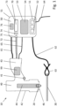
- a welding device 10 for welding a welding stud 20 to a substrate 30 is shown schematically.
- a material of the welding stud 20 and a material of the substrate 30 are electrically conductive, in particular metallic.
- the welding device 10 comprises a welding gun 40 with a trigger switch 41 designed as a pushbutton switch, a welding device 50 with a housing 51, a first electrical cable 61, a second electrical cable 62 with a connection terminal 63, an electrical supply cable 64 designed, for example, as a mains cable, an electrical communication line 65, a gas container 70 designed as a gas can or gas bottle and a gas line 72 designed as a gas hose.
- the first cable 61 is used to supply the welding stud 20 with electrical current through the welding device 50.
- the second cable 62 is used to electrically connect the base 30 to the welding device 50 when the connection terminal 63 is clamped to the base 30.
- an electrical circuit is closed so that the welding stud 20 can be supplied with welding current from the welding device 50, which is designed as direct current or alternating current, for example.
- the welding gun 40 comprises a Fig. 1 welding current contact element (not shown).
- the welding device 50 comprises a device (not shown) for converting electrical current from the supply cable 64 into welding current, which comprises, for example, an electrical capacitor, a thyristor, a bipolar transistor with an insulated gate electrode or other power electronic components and an associated control device with a microprocessor in order to provide the welding current with the desired voltage and current intensity.
- a device for converting electrical current from the supply cable 64 into welding current, which comprises, for example, an electrical capacitor, a thyristor, a bipolar transistor with an insulated gate electrode or other power electronic components and an associated control device with a microprocessor in order to provide the welding current with the desired voltage and current intensity.
- the welding device 50 has an input device 51 with actuating elements 52 and an output device 53 with a visual display element 54 and a wireless transmission unit.
- the input device 51 is used for the input of parameters of a welding process to be carried out with the welding device 10, such as the electrical voltage, current intensity, power and duration of the welding current, position and speed of the bolt and so on, by a user of the welding device 10.
- the output device 53 is used to output information, such as information about parameters of the welding process, information about recorded emissions of the welding process or other variables, information about a quality of the welding process, information about measures to improve the welding process, information about recorded properties of the welding bolt or information derived from the aforementioned variables, and/or recommendations or instructions for cleaning and/or maintaining the welding device 10, in particular the welding gun 40, to the user.
- the communication line 65 is used for communication between the welding gun 40, in particular a Fig. 1 not shown control device of the welding gun 40, and the welding device 50, in particular the control device and/or the input device 51 and/or the output device 53.
- This communication enables, for example, an exchange of information about the parameters of a welding process in order to for example, to achieve or facilitate a synchronization of the welding current with a movement of the welding bolt 20.
- the communication between the welding gun and the welding device takes place wirelessly, by radio or by means of the first electrical cable which carries the welding current.
- the welding gun 40 has a housing 42 with a mouth 46, from which a handle 43 with the trigger switch 41 protrudes.
- the welding gun 40 also has a stud holder 44, on which the welding stud 20 is held during a welding process.
- the stud holder comprises, for example, two, three, four or more springy arms (not shown in detail), between which the welding stud 20 is inserted and held by means of a clamp fit.
- the welding gun 40 also has a welding current contact element for applying a welding current to the welding stud 20, which is integrated in the stud holder 44, for example in the form of one or more of the springy arms.
- the welding gun 40 also has a control device 99 for controlling the various components and devices of the welding gun and the welding device 50.
- the control device 99 is provided for controlling one or more parameters of the welding process.
- the control device 99 comprises various electronic components, such as one or more microprocessors, one or more temporary or permanent data memories and the like.
- the welding gun 40 further comprises a bolt lifting device designed as a first lifting magnet, which moves the bolt holder 44 with a force away from the muzzle 46 to the rear (in Fig. 1 upwards) when the bolt lifting device is activated.
- the control device 99 communicates with the bolt lifting device via a signal line (not shown) in order to control the bolt lifting device, in particular to activate and deactivate it.
- the welding gun 40 further comprises a stud immersion device designed as a spring element or as a second lifting magnet, which pushes the stud holder 44 forwards (in Fig. 1 downwards) when the bolt insertion device is activated.
- the control device 99 communicates with the bolt insertion device via a signal line (not shown) in order to control the bolt insertion device, in particular to activate and deactivate it.
- the bolt insertion device is designed as a spring element, this spring element is preferably tensioned when the bolt holder is moved backwards by the bolt lifting device. is moved so that the spring element moves the bolt holder forward as soon as the bolt lifting device is deactivated.
- the welding device 50 has a gas container holder 73 arranged in the housing 51, in which the gas container 70 is exchangeably received so that the gas container 70 is carried by the welding device 50.
- the gas container is attached, in particular fastened, to the outside of the welding device, for example to its housing.
- the gas line 72 has a gas connection element 74, which is arranged on the gas container holder 73 for connecting the gas container 70 to the gas line 72.
- the welding device 10 and in particular the welding device 50 has a gas flow control device 75 designed as a valve, in particular a solenoid valve, for controlling a gas flow through the gas line 72, wherein the gas flow is controlled, for example, by setting a cross-sectional area of the gas flow control device 75 or by setting a time duration or frequency of one or more open phases of the gas flow control device 75.
- the control of the gas flow is preferably coordinated with the other parameters of the welding process and/or the gas volume in the gas line 72.
- the gas flow control device 75 is arranged entirely in the housing 51 and carried by the welding device 50 and serves to control a gas flow to the contact area between the welding stud 20 and the substrate 30.
- the gas flow control device 75 comprises a controllable valve which is controlled, for example, by the control device 99.
- the control device 99 is intended to open the valve during a predetermined period of time in order to flush the gas line 72 with gas from the gas container and to initiate a welding process or to signal to a user of the welding device 10 that the welding device 10 is ready for a welding process when the predetermined period of time has elapsed.
- the automated flushing of the gas line 72 may reduce the waiting time before a welding process and/or the gas consumption.
- the welding device 10 and in particular the welding device 50 has a fill level detection device 76 for the gas container 70.
- the fill level detection device 76 is preferably arranged completely in the housing 51 and carried by the welding device 50.
- the fill level detection device 76 comprises a pressure sensor arranged in the gas line 72, for example on the gas connection element 74, for measuring the internal pressure of the gas container and a data processing device which detects the number of welds that have taken place.
- the fill level detection device comprises a sensor in particular for measuring the weight or inertia of the gas container, the pressure or temperature gradient during regulation of the gas flow, an acoustic response of the gas container contents or the like.
- the fill level detection device 76 comprises a storage medium which is attached to the gas container 70 and a data processing device which is carried by the welding device and is suitable for storing information about a fill level of the gas container 70 on the storage medium and/or reading it from the memory and/or outputting it by means of the output device 53, for example its display element 54.
- the substrate 30 and the bolt 20 are first made available.
- a user enters information via the input device, for example about desired parameters of the subsequent welding process.
- the welding bolt 20 is subjected to a welding current between the welding bolt 20 and the substrate 30 by the welding device 50 using the first cable 61 and the second cable 62.
- the welding bolt 20 is lifted off the substrate by means of the bolt lifting device while maintaining the welding current flowing between the welding bolt 20 and the substrate 30, whereby an arc forms between the welding bolt 20 and the substrate 30.
- a material of the welding bolt 20 and/or the substrate 30 is then partially liquefied.
- the welding stud 20 is immersed in the liquefied material of the welding stud 20 or the substrate 30 by means of the stud immersion device.
- the liquefied material of the welding stud 20 or the substrate 30 then solidifies, so that the welding stud 20 is firmly bonded to the substrate 30.
- the valve of the gas flow control device 75 is opened for a predetermined period of time, and the welding stud 20 is welded to the substrate 30 while the welding stud 20 gas from the gas container 70 flows around it.
- the welding of the welding stud 20 to the substrate 30 is initiated when the predetermined period of time has elapsed.
- a user of the welding device 10 is signaled that the device is ready for a welding process when the predetermined period of time has elapsed.
- This automatic flushing of the gas line is preferably always carried out, in particular only when the welding device 10 is switched on and/or after a longer downtime and/or after replacing parts of the gas line 72.
- the individual process steps are controlled by the control device 99, which in particular also regulates the parameters of the welding process, such as an electrical voltage, a current strength and a duration of the welding current, or a time and a speed of the bolt movement, or a bolt position, or a gas flow through the gas line 72. Furthermore, a fill level of the gas container 70 and the number of welds carried out are detected, stored and output.
- the parameters of the welding process such as an electrical voltage, a current strength and a duration of the welding current, or a time and a speed of the bolt movement, or a bolt position, or a gas flow through the gas line 72.
- the invention has been described using examples of a device for fastening a first object to a second object and a manufacturing method for such a device.
- the features of the described embodiments can also be combined with one another as desired within a single fastening device or a single manufacturing method. It is pointed out that the device according to the invention and the method according to the invention are also suitable for other purposes.
Landscapes
- Engineering & Computer Science (AREA)
- Mechanical Engineering (AREA)
- Physics & Mathematics (AREA)
- Plasma & Fusion (AREA)
- Arc Welding In General (AREA)
- Arc Welding Control (AREA)
- Resistance Welding (AREA)
- Filling Or Discharging Of Gas Storage Vessels (AREA)
Claims (9)
- Dispositif (10) permettant de souder des goujons à souder (20) sur un support (30), à l'aide d'un pistolet à souder (40) qui comprend un porte-goujon (44) pour respectivement un goujon à souder (20), comprenant un poste de soudure (50), un réservoir de gaz (70), une conduite de gaz (72) pour acheminer le gaz du réservoir de gaz (70) au porte-goujon (44), une vanne disposée dans la conduite de gaz (72), et un dispositif de commande (99) pour commander la vanne,
caractérisé en ce que le dispositif de commande (99) est prévu pour ouvrir la vanne pendant une période prédéterminée avant le début d'un processus de soudage pour rincer automatiquement la conduite de gaz (72) avec le gaz provenant du réservoir de gaz (70) uniquement lorsque le dispositif (10) est mis en service et/ou après un temps d'arrêt du dispositif (10). - Dispositif selon la revendication 1, dans lequel le dispositif de commande (99) est prévu pour lancer un processus de soudage lorsque la période prédéterminée s'est écoulée.
- Dispositif selon la revendication 1, dans lequel le dispositif de commande (99) est prévu pour signaler à un utilisateur du dispositif (10) la disponibilité du dispositif (10) pour un processus de soudage lorsque la période prédéterminée s'est écoulée.
- Dispositif selon l'une quelconque des revendications précédentes, dans lequel le réservoir de gaz (70) est porté par le poste de soudure (50), la conduite de gaz (72) et/ou le pistolet à souder (40).
- Dispositif selon l'une quelconque des revendications précédentes, présentant en outre un dispositif de régulation de débit de gaz (75) pour réguler un débit de gaz à travers la conduite de gaz (72), le dispositif de régulation de débit de gaz (75) comprenant une vanne.
- Dispositif selon l'une quelconque des revendications précédentes, présentant en outre un premier câble électrique (61) pour conduire un courant de soudage du poste de soudure (50) au pistolet à souder (40) et un deuxième câble électrique (62) pour conduire le courant de soudage du support (30) au poste de soudure.
- Procédé permettant de souder des goujons à souder (20) sur un support (30), comprenant les étapes consistant àa) fournir un dispositif (10) comprenant un pistolet à souder (40) qui comprend un porte-goujon (44) pour respectivement un goujon à souder (20), un poste de soudure, un réservoir de gaz (70), une conduite de gaz (72) pour conduire du gaz du réservoir de gaz (70) au porte-goujon, et une vanne disposée dans la conduite de gaz (72),b) ouvrir la vanne pendant une période prédéterminée pour rincer automatiquement la conduite de gaz (72) avec le gaz provenant du réservoir de gaz (70), etc) souder le goujon à souder (20) respectif sur le support (30) pendant que le goujon à souder (20) est entouré de gaz provenant du réservoir de gaz (70),caractérisé en ce qu'à l'étape b), la vanne est ouverte pendant la période prédéterminée avant le début du processus de soudage uniquement lorsque le dispositif (10) est mis en service et/ou après un temps d'arrêt du dispositif (10) et/ou après un remplacement de pièces de la conduite de gaz (72).
- Procédé selon la revendication 7, dans lequel l'étape c) est lancée lorsque la période de temps s'est écoulée.
- Procédé selon la revendication 7, dans lequel la disponibilité du dispositif (10) pour un processus de soudage est signalée à un utilisateur du dispositif (10) lorsque la période prédéterminée s'est écoulée.
Applications Claiming Priority (2)
| Application Number | Priority Date | Filing Date | Title |
|---|---|---|---|
| EP17195603.0A EP3470157A1 (fr) | 2017-10-10 | 2017-10-10 | Dispositif de soudage et procédé de soudage |
| PCT/EP2018/077105 WO2019072705A1 (fr) | 2017-10-10 | 2018-10-05 | Unité de soudage et procédé de soudage |
Publications (3)
| Publication Number | Publication Date |
|---|---|
| EP3694672A1 EP3694672A1 (fr) | 2020-08-19 |
| EP3694672C0 EP3694672C0 (fr) | 2024-12-04 |
| EP3694672B1 true EP3694672B1 (fr) | 2024-12-04 |
Family
ID=60051428
Family Applications (2)
| Application Number | Title | Priority Date | Filing Date |
|---|---|---|---|
| EP17195603.0A Withdrawn EP3470157A1 (fr) | 2017-10-10 | 2017-10-10 | Dispositif de soudage et procédé de soudage |
| EP18782070.9A Active EP3694672B1 (fr) | 2017-10-10 | 2018-10-05 | Dispositif de soudage et procédé de soudage |
Family Applications Before (1)
| Application Number | Title | Priority Date | Filing Date |
|---|---|---|---|
| EP17195603.0A Withdrawn EP3470157A1 (fr) | 2017-10-10 | 2017-10-10 | Dispositif de soudage et procédé de soudage |
Country Status (7)
| Country | Link |
|---|---|
| US (1) | US20200238427A1 (fr) |
| EP (2) | EP3470157A1 (fr) |
| JP (1) | JP2020535019A (fr) |
| KR (1) | KR20200063205A (fr) |
| CN (1) | CN111246958A (fr) |
| TW (1) | TW201934233A (fr) |
| WO (1) | WO2019072705A1 (fr) |
Families Citing this family (1)
| Publication number | Priority date | Publication date | Assignee | Title |
|---|---|---|---|---|
| CN113857634A (zh) * | 2021-09-26 | 2021-12-31 | 广东锐气科技有限公司 | 焊接设备中保护气体的智能控制方法 |
Family Cites Families (13)
| Publication number | Priority date | Publication date | Assignee | Title |
|---|---|---|---|---|
| US2491479A (en) * | 1948-11-12 | 1949-12-20 | Dash Edward | Arc welding of studs |
| US3790740A (en) * | 1970-07-09 | 1974-02-05 | Trw Inc | Through deck welding |
| US3823575A (en) * | 1971-06-07 | 1974-07-16 | Univ Melbourne | Cryogenic apparatus |
| US4201904A (en) * | 1978-05-22 | 1980-05-06 | Geo. P. Reintjes Co., Inc. | Air cooled head for stud welding gun |
| US7306133B2 (en) * | 2003-04-25 | 2007-12-11 | St Assembly Test Services Ltd. | System for fabricating an integrated circuit package on a printed circuit board |
| US20080223830A1 (en) * | 2004-05-12 | 2008-09-18 | Eugene Gibbons | Shielding gas cylinder holder for welding-type devices |
| DE502005011214D1 (de) * | 2005-02-25 | 2011-05-19 | Trumpf Werkzeugmaschinen Gmbh | Verfahren zum Spülen von Leitungen und/oder Hohlräumen einer Laserbearbeitungsmaschine |
| US8502106B2 (en) * | 2006-05-15 | 2013-08-06 | Illinois Tool Works Inc. | Welding system and method having power controller with workpiece sensor |
| JP6035465B2 (ja) * | 2013-02-25 | 2016-11-30 | 株式会社スター | ビット溶着用ガン |
| CN204035769U (zh) * | 2014-07-14 | 2014-12-24 | 中国人民解放军海军潜艇学院 | 一种水下螺柱焊枪 |
| CN204449578U (zh) * | 2015-01-30 | 2015-07-08 | 永胜机械工业(昆山)有限公司 | 立式螺母焊接装置 |
| US20170036290A1 (en) * | 2015-08-06 | 2017-02-09 | Lincoln Global, Inc. | Engine drive welder and methods and systems of controlling the same |
| US10894296B2 (en) * | 2015-08-20 | 2021-01-19 | Nelson Stud Welding, Inc. | Light weight cordless stud welder |
-
2017
- 2017-10-10 EP EP17195603.0A patent/EP3470157A1/fr not_active Withdrawn
-
2018
- 2018-09-17 TW TW107132632A patent/TW201934233A/zh unknown
- 2018-10-05 WO PCT/EP2018/077105 patent/WO2019072705A1/fr not_active Ceased
- 2018-10-05 CN CN201880064921.0A patent/CN111246958A/zh active Pending
- 2018-10-05 KR KR1020207012660A patent/KR20200063205A/ko not_active Ceased
- 2018-10-05 JP JP2020517418A patent/JP2020535019A/ja active Pending
- 2018-10-05 US US16/652,729 patent/US20200238427A1/en not_active Abandoned
- 2018-10-05 EP EP18782070.9A patent/EP3694672B1/fr active Active
Also Published As
| Publication number | Publication date |
|---|---|
| WO2019072705A1 (fr) | 2019-04-18 |
| TW201934233A (zh) | 2019-09-01 |
| CN111246958A (zh) | 2020-06-05 |
| JP2020535019A (ja) | 2020-12-03 |
| EP3694672A1 (fr) | 2020-08-19 |
| KR20200063205A (ko) | 2020-06-04 |
| US20200238427A1 (en) | 2020-07-30 |
| EP3694672C0 (fr) | 2024-12-04 |
| EP3470157A1 (fr) | 2019-04-17 |
Similar Documents
| Publication | Publication Date | Title |
|---|---|---|
| WO2019120781A2 (fr) | Système de fixation | |
| EP3694672B1 (fr) | Dispositif de soudage et procédé de soudage | |
| EP3691820A1 (fr) | Dispositif et procédé de soudage | |
| EP3694674B1 (fr) | Dispositif de soudage | |
| EP3691825A1 (fr) | Dispositif et procédé de soudage | |
| EP4076820A1 (fr) | Dispositif de soudage et procédé de soudage | |
| EP3898056B1 (fr) | Dispositif de soudage | |
| EP3727738B1 (fr) | Pistolet de soudage de goujons et procédé | |
| WO2019072671A1 (fr) | Unité de soudage | |
| WO2019068624A1 (fr) | Dispositif et procédé de soudage | |
| EP3694675B1 (fr) | Boulon et dispositif de fixation | |
| WO2019110241A1 (fr) | Dispositif et procédé de soudage de goujons | |
| WO2019072731A1 (fr) | Procédé de fixation | |
| EP4440765A1 (fr) | Procédé de fixation | |
| WO2019072627A1 (fr) | Goujon à souder et pistolet de soudage | |
| WO2019068672A1 (fr) | Dispositif et procédé de soudage | |
| WO2019068495A1 (fr) | Dispositif et procédé de soudage | |
| EP3691821A1 (fr) | Dispositif et procédé de soudage | |
| EP4015132A1 (fr) | Dispositif de soudage de goujon sur une pièce avec répartition de gaz |
Legal Events
| Date | Code | Title | Description |
|---|---|---|---|
| STAA | Information on the status of an ep patent application or granted ep patent |
Free format text: STATUS: UNKNOWN |
|
| STAA | Information on the status of an ep patent application or granted ep patent |
Free format text: STATUS: THE INTERNATIONAL PUBLICATION HAS BEEN MADE |
|
| PUAI | Public reference made under article 153(3) epc to a published international application that has entered the european phase |
Free format text: ORIGINAL CODE: 0009012 |
|
| STAA | Information on the status of an ep patent application or granted ep patent |
Free format text: STATUS: REQUEST FOR EXAMINATION WAS MADE |
|
| 17P | Request for examination filed |
Effective date: 20200511 |
|
| AK | Designated contracting states |
Kind code of ref document: A1 Designated state(s): AL AT BE BG CH CY CZ DE DK EE ES FI FR GB GR HR HU IE IS IT LI LT LU LV MC MK MT NL NO PL PT RO RS SE SI SK SM TR |
|
| AX | Request for extension of the european patent |
Extension state: BA ME |
|
| DAV | Request for validation of the european patent (deleted) | ||
| DAX | Request for extension of the european patent (deleted) | ||
| STAA | Information on the status of an ep patent application or granted ep patent |
Free format text: STATUS: EXAMINATION IS IN PROGRESS |
|
| 17Q | First examination report despatched |
Effective date: 20230927 |
|
| GRAP | Despatch of communication of intention to grant a patent |
Free format text: ORIGINAL CODE: EPIDOSNIGR1 |
|
| STAA | Information on the status of an ep patent application or granted ep patent |
Free format text: STATUS: GRANT OF PATENT IS INTENDED |
|
| INTG | Intention to grant announced |
Effective date: 20240726 |
|
| GRAS | Grant fee paid |
Free format text: ORIGINAL CODE: EPIDOSNIGR3 |
|
| GRAA | (expected) grant |
Free format text: ORIGINAL CODE: 0009210 |
|
| STAA | Information on the status of an ep patent application or granted ep patent |
Free format text: STATUS: THE PATENT HAS BEEN GRANTED |
|
| AK | Designated contracting states |
Kind code of ref document: B1 Designated state(s): AL AT BE BG CH CY CZ DE DK EE ES FI FR GB GR HR HU IE IS IT LI LT LU LV MC MK MT NL NO PL PT RO RS SE SI SK SM TR |
|
| REG | Reference to a national code |
Ref country code: GB Ref legal event code: FG4D Free format text: NOT ENGLISH |
|
| REG | Reference to a national code |
Ref country code: CH Ref legal event code: EP |
|
| REG | Reference to a national code |
Ref country code: DE Ref legal event code: R096 Ref document number: 502018015392 Country of ref document: DE |
|
| REG | Reference to a national code |
Ref country code: IE Ref legal event code: FG4D Free format text: LANGUAGE OF EP DOCUMENT: GERMAN |
|
| U01 | Request for unitary effect filed |
Effective date: 20241210 |
|
| U07 | Unitary effect registered |
Designated state(s): AT BE BG DE DK EE FI FR IT LT LU LV MT NL PT RO SE SI Effective date: 20241219 |
|
| PG25 | Lapsed in a contracting state [announced via postgrant information from national office to epo] |
Ref country code: HR Free format text: LAPSE BECAUSE OF FAILURE TO SUBMIT A TRANSLATION OF THE DESCRIPTION OR TO PAY THE FEE WITHIN THE PRESCRIBED TIME-LIMIT Effective date: 20241204 |
|
| PG25 | Lapsed in a contracting state [announced via postgrant information from national office to epo] |
Ref country code: ES Free format text: LAPSE BECAUSE OF FAILURE TO SUBMIT A TRANSLATION OF THE DESCRIPTION OR TO PAY THE FEE WITHIN THE PRESCRIBED TIME-LIMIT Effective date: 20241204 |
|
| PG25 | Lapsed in a contracting state [announced via postgrant information from national office to epo] |
Ref country code: NO Free format text: LAPSE BECAUSE OF FAILURE TO SUBMIT A TRANSLATION OF THE DESCRIPTION OR TO PAY THE FEE WITHIN THE PRESCRIBED TIME-LIMIT Effective date: 20250304 |
|
| PG25 | Lapsed in a contracting state [announced via postgrant information from national office to epo] |
Ref country code: GR Free format text: LAPSE BECAUSE OF FAILURE TO SUBMIT A TRANSLATION OF THE DESCRIPTION OR TO PAY THE FEE WITHIN THE PRESCRIBED TIME-LIMIT Effective date: 20250305 |
|
| PG25 | Lapsed in a contracting state [announced via postgrant information from national office to epo] |
Ref country code: RS Free format text: LAPSE BECAUSE OF FAILURE TO SUBMIT A TRANSLATION OF THE DESCRIPTION OR TO PAY THE FEE WITHIN THE PRESCRIBED TIME-LIMIT Effective date: 20250304 |
|
| PG25 | Lapsed in a contracting state [announced via postgrant information from national office to epo] |
Ref country code: SM Free format text: LAPSE BECAUSE OF FAILURE TO SUBMIT A TRANSLATION OF THE DESCRIPTION OR TO PAY THE FEE WITHIN THE PRESCRIBED TIME-LIMIT Effective date: 20241204 |
|
| PG25 | Lapsed in a contracting state [announced via postgrant information from national office to epo] |
Ref country code: PL Free format text: LAPSE BECAUSE OF FAILURE TO SUBMIT A TRANSLATION OF THE DESCRIPTION OR TO PAY THE FEE WITHIN THE PRESCRIBED TIME-LIMIT Effective date: 20241204 |
|
| PG25 | Lapsed in a contracting state [announced via postgrant information from national office to epo] |
Ref country code: IS Free format text: LAPSE BECAUSE OF FAILURE TO SUBMIT A TRANSLATION OF THE DESCRIPTION OR TO PAY THE FEE WITHIN THE PRESCRIBED TIME-LIMIT Effective date: 20250404 |
|
| PG25 | Lapsed in a contracting state [announced via postgrant information from national office to epo] |
Ref country code: SK Free format text: LAPSE BECAUSE OF FAILURE TO SUBMIT A TRANSLATION OF THE DESCRIPTION OR TO PAY THE FEE WITHIN THE PRESCRIBED TIME-LIMIT Effective date: 20241204 |
|
| PG25 | Lapsed in a contracting state [announced via postgrant information from national office to epo] |
Ref country code: CZ Free format text: LAPSE BECAUSE OF FAILURE TO SUBMIT A TRANSLATION OF THE DESCRIPTION OR TO PAY THE FEE WITHIN THE PRESCRIBED TIME-LIMIT Effective date: 20241204 |
|
| PLBE | No opposition filed within time limit |
Free format text: ORIGINAL CODE: 0009261 |
|
| STAA | Information on the status of an ep patent application or granted ep patent |
Free format text: STATUS: NO OPPOSITION FILED WITHIN TIME LIMIT |
|
| 26N | No opposition filed |
Effective date: 20250905 |
|
| U20 | Renewal fee for the european patent with unitary effect paid |
Year of fee payment: 8 Effective date: 20251028 |