EP3695426B1 - Magnetanordnung und verfahren zu deren herstellung - Google Patents
Magnetanordnung und verfahren zu deren herstellung Download PDFInfo
- Publication number
- EP3695426B1 EP3695426B1 EP17790695.5A EP17790695A EP3695426B1 EP 3695426 B1 EP3695426 B1 EP 3695426B1 EP 17790695 A EP17790695 A EP 17790695A EP 3695426 B1 EP3695426 B1 EP 3695426B1
- Authority
- EP
- European Patent Office
- Prior art keywords
- flange
- plastic
- recess
- recesses
- radial direction
- Prior art date
- Legal status (The legal status is an assumption and is not a legal conclusion. Google has not performed a legal analysis and makes no representation as to the accuracy of the status listed.)
- Active
Links
Images

Classifications
-
- H—ELECTRICITY
- H01—ELECTRIC ELEMENTS
- H01F—MAGNETS; INDUCTANCES; TRANSFORMERS; SELECTION OF MATERIALS FOR THEIR MAGNETIC PROPERTIES
- H01F7/00—Magnets
- H01F7/02—Permanent magnets [PM]
- H01F7/0231—Magnetic circuits with PM for power or force generation
- H01F7/0252—PM holding devices
-
- H—ELECTRICITY
- H01—ELECTRIC ELEMENTS
- H01F—MAGNETS; INDUCTANCES; TRANSFORMERS; SELECTION OF MATERIALS FOR THEIR MAGNETIC PROPERTIES
- H01F7/00—Magnets
- H01F7/02—Permanent magnets [PM]
- H01F7/0205—Magnetic circuits with PM in general
- H01F7/021—Construction of PM
-
- H—ELECTRICITY
- H01—ELECTRIC ELEMENTS
- H01F—MAGNETS; INDUCTANCES; TRANSFORMERS; SELECTION OF MATERIALS FOR THEIR MAGNETIC PROPERTIES
- H01F7/00—Magnets
- H01F7/02—Permanent magnets [PM]
- H01F7/0205—Magnetic circuits with PM in general
- H01F7/0221—Mounting means for PM, supporting, coating, encapsulating PM
-
- G—PHYSICS
- G01—MEASURING; TESTING
- G01D—MEASURING NOT SPECIALLY ADAPTED FOR A SPECIFIC VARIABLE; ARRANGEMENTS FOR MEASURING TWO OR MORE VARIABLES NOT COVERED IN A SINGLE OTHER SUBCLASS; TARIFF METERING APPARATUS; MEASURING OR TESTING NOT OTHERWISE PROVIDED FOR
- G01D5/00—Mechanical means for transferring the output of a sensing member; Means for converting the output of a sensing member to another variable where the form or nature of the sensing member does not constrain the means for converting; Transducers not specially adapted for a specific variable
- G01D5/12—Mechanical means for transferring the output of a sensing member; Means for converting the output of a sensing member to another variable where the form or nature of the sensing member does not constrain the means for converting; Transducers not specially adapted for a specific variable using electric or magnetic means
- G01D5/244—Mechanical means for transferring the output of a sensing member; Means for converting the output of a sensing member to another variable where the form or nature of the sensing member does not constrain the means for converting; Transducers not specially adapted for a specific variable using electric or magnetic means influencing characteristics of pulses or pulse trains; generating pulses or pulse trains
- G01D5/24428—Error prevention
- G01D5/24433—Error prevention by mechanical means
- G01D5/24442—Error prevention by mechanical means by mounting means
Definitions
- the invention relates to a magnet arrangement comprising a carrier sleeve which has a collar with a front side and a back side, to which collar a ring-shaped plastic-bonded permanent magnet is attached to the back side of the collar directly adjacent to the collar and is permanently connected to the collar.
- the invention further relates to a method for producing a magnet arrangement.
- EP 1 123 794 proposes to add another component in the form of an intermediate element made of elastic plastic material between the The main body and the magnetic plastic part should be provided so that the plastic part is not connected directly to the metal main body but via the intermediate element.
- Such a solution with an intermediate element is also used by DE 10 2008 047 466 A1 proposed, which document also concerns a magnet arrangement with a magnet ring produced by a plastic injection molding process and a metal carrier sleeve for the magnet ring.
- the solutions mentioned have proven themselves, but are complex to manufacture.
- DE 198 36 451 A1 proposes a solution without an intermediate element, in which the highly filled plastic part or the plastic-bonded permanent magnet is molded directly onto the metal base body, whereby this base body has tab-shaped parts that extend into the plastic-bonded permanent magnet.
- This solution is intended to counteract the shrinkage of the permanent magnet when it cools down after injection molding, in that the tab-shaped parts are intended to absorb the shrinkage stresses of the magnet material after injection molding by bending the tab-shaped parts.
- large temperature differences must also be taken into account during use. Such temperature differences can lead to the tabs damaging the magnet material.
- DE 10 2009 039 082 A1 proposes to manufacture the magnet ring separately and to provide it with domes.
- the magnet ring and the carrier sleeve are connected to each other by guiding the domes through openings in the collar of the carrier sleeve and deforming the areas of the domes that protrude beyond the carrier sleeve so that the plastic-bonded permanent magnet is attached to the carrier sleeve in a similar way to a rivet connection.
- WO 2017/120687 A1 is used to attach the plastic-bonded permanent magnet to the flange of a sleeve a bayonet-type positive connection is proposed.
- an additional blocking device is provided, which results in a corresponding manufacturing effort.
- the invention is based on the object of creating a magnet arrangement which withstands changing thermal loads and is nevertheless particularly simple and cost-effective to produce.
- a plastic-bonded permanent magnet is connected to a carrier sleeve, and in particular a metal carrier sleeve, in such a way that the plastic-bonded permanent magnet rests directly, without an intermediate part, on a collar of the carrier sleeve and that formations of the plastic-bonded permanent magnet form a positive connection between the plastic part and the carrier sleeve, which connects them in the direction of the common central longitudinal axis of the plastic part and the carrier sleeve, in that the formations pass through recesses in the collar of the carrier sleeve.
- the magnet arrangement allows easy manufacture by directly injecting the plastic-bonded permanent magnet onto the carrier sleeve in an injection molding tool, and on the other hand, it is durable even under operating conditions with temperature fluctuations, since relative movements between the formations of the plastic-bonded permanent magnet and the carrier sleeve are made possible.
- the plastic-bonded permanent magnet injected onto the carrier sleeve is magnetized in the conventional way after injection molding and demolding, which is known to those skilled in the art and does not need to be explained further here.
- the magnet arrangement preferably has two or four recesses and two or four formations arranged in each of these, which recesses or formations are arranged diametrically opposite one another on the carrier sleeve.
- three recesses and three formations can be provided, which are provided at an equal distance along the carrier sleeve.
- a permanently secure attachment between the carrier sleeve and the plastic-bonded permanent magnet can be achieved with just two recesses and associated formations. If more than two recesses and formations are provided, increased security of the attachment can be achieved.
- the respective shape overlaps the recess on both sides of the recess and thus lies directly on the collar or on the front on both sides of the recess. It is also preferred that the respective recess on the collar is open at the edge. This allows the shape to be formed flush with the collar of the carrier sleeve during injection molding. In this case, the free area of the recess extends radially between the formation and the cylindrical sleeve part of the carrier sleeve. Such an example is described in more detail below.
- the recesses in the collar are essentially rectangular.
- a different shape is possible, but the shape must fundamentally ensure that the respective formation with its part lying in the recess can be moved in the radial direction in the recess.
- the free area of the recess in the radial direction is 0.5 mm to 1.5 mm in size, in particular approx. 1.0 mm.
- the invention is further based on the object of creating a simple and efficient manufacturing method for an improved magnet arrangement.
- a carrier sleeve with a front-side collar which has a front side and a back side and recesses
- a plastic injection mold which plastic injection mold has a molding space for forming a ring-shaped plastic-bonded permanent magnet on the back side of the collar and molding spaces for forming moldings of the plastic-bonded permanent magnet in the recesses of the collar and on the front side of the collar, which moldings each overlap the collar on its front side adjacent to the respective recess and lie directly on the collar
- the plastic injection mold has molded parts which engage in a part of the respective recesses of the collar, so that at least one area of the recesses lying in the radial direction on the inner edge of the respective recess is filled by the molded parts, and that a plastic mass provided with magnetizable particles is injected into the plastic injection mold to form the ring-shaped permanent magnet and its moldings and that after solidification of the plastic material, the magnet arrangement is demolded.
- At least one of the formations of the plastic-bonded permanent magnet is narrower in the radial direction R of the carrier sleeve than the associated recess of the collar, such that an area of the recess is exposed in the radial direction towards the carrier sleeve, the respective formation overlaps the recess on both sides of the recess and the area of the recess that is free in the radial direction is a maximum of 1.5 mm in size in the radial direction.
- the method can be used to achieve a direct connection between the magnetic plastic part and the carrier sleeve, which results in a permanent and long-term stable connection.
- the direct connection eliminates the need for an intermediate element and the step of manufacturing it, which makes the magnet arrangement according to the invention more efficient and therefore more cost-effective to manufacture.
- This manufacturing process ensures that the formation is free in the radial direction in the collar, so that it can basically move within the recess. It turns out that thermally induced relative movements between the permanent magnet and the, usually metallic, carrier sleeve, such as can occur during operation of the magnet arrangement, can be permanently controlled without damaging the plastic-bonded permanent magnet and thus causing the magnet arrangement to fail.
- the solution of the invention allows the plastic-bonded permanent magnet to be directly molded onto the carrier sleeve, thus enabling very cost-effective and efficient production without additional parts.
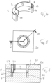
- Figure 1 an example of a carrier sleeve 2 of the magnet arrangement 1 in a diagrammatic representation.
- the carrier sleeve 2 is usually made of metal and has a generally cylindrical sleeve part 13 and a flange or collar 3.
- One side of the collar 3 can be the front side 10 and the other side the back side 11 ( Figure 4 ), although these are only designations within the scope of this description and the two sides of the waistband could also be defined conversely as front and back.
- the waistband has a circumference or Edge 7.
- the rear side 11 forms the system for the injection molding of the plastic-bonded permanent magnet 4. In this respect, this basically corresponds to the known structure of a magnet arrangement.
- the radial direction is referred to below as the direction R pointing from the longitudinal center axis M of the carrier sleeve 2 outwards to the edge 7 of the collar 3 and as an example in Figure 1 a radial arrow with the designation R is entered.
- a magnet arrangement 1 is shown diagrammatically in Figure 2 and has a ring-shaped plastic part which has magnetic properties and which is referred to as a plastic-bonded permanent magnet.
- plastic-bonded permanent magnets are generally known to the person skilled in the art, as is their production by injection molding.
- the plastic-bonded permanent magnet 4 has, after its formation or shaping by injection molding and after a subsequent magnetization process, a sequence of magnetic north and south poles along its circumference, which can be detected in a rotation angle and torque measuring arrangement of magnetic field sensors. This is also known to the person skilled in the art and will not be explained further here.
- the collar 3 of the carrier sleeve 2 according to the invention has recesses 5.
- these are four recesses 5, which are arranged evenly along the circumference or edge 7 of the collar 3.
- the recesses have essentially parallel side walls 15 and a rear wall 25 and can have a rectangular or square outline. In Figure 1 the floor plan is shown as rectangular.
- a floor plan in triangular form with the back wall as the longest side or a floor plan in parallelogram form with the back wall as the longest side of the shape is also
- the recesses on the circumference or edge 7 of the collar 3 are open, as in Figure 1 shown.
- the plastic-bonded permanent magnet 4 molded onto the collar 3 has protrusions 8, each of which protrudes through the recesses 5 and thus extends from the rear side 11 of the collar 3 through the recess to the front side 10 of the collar 3. These protrusions overlap at least one of the side walls 15 of the recesses 5 on the front side 10 of the collar, preferably both of the side walls 15, as shown, and thus extend over the front side 10.
- the protrusions, with their sections overlapping the side walls 15, lie directly on the front side 10 of the collar and thus form a positive, firm connection of the plastic-bonded permanent magnet 4 to the collar 3 and thus to the carrier sleeve 2.
- the number of protrusions 8 generally corresponds to the number of recesses 5. At most, fewer protrusions than recesses can be provided.
- the formations 8 of the permanent magnet 4 are preferably formed directly during the injection molding process of the permanent magnet 4 on the carrier sleeve 2 or on the collar 3.
- the formations 8 are thus created in the same operation in the mold or in the plastic injection mold in which the cylindrical part of the permanent magnet 4 is formed.
- the part of the permanent magnet 4 that is injected onto the back 11 of the collar 3 is formed in a first operation and the formations 8 are injected in a separate second operation. If necessary, part of the respective formation can also be formed in the first operation and the rest of the formation in the second operation.
- the formation of the permanent magnet with all formations in a single operation is preferred.
- the respective recess 5 is thus free in the radial direction R between the formation 8 and the sleeve part.
- This is shown in Figure 3 in a top view of the magnet arrangement 1, it is clearly visible in which figure the free areas 17 of each recess are visible.
- such free areas 17 are provided in each recess.
- the radial distance between the respective formation 8 and the rear wall 25 of the recess or the respective width of the free area 17 is preferably in the range of 0.5 millimeters to 1.5 millimeters and in particular approximately 1 millimeter.
- the free areas of the recesses ensure that the different expansion or contraction of magnet 4 and carrier sleeve 2 resulting from temperature differences when using the magnet arrangement, in particular when used in the automotive sector, can take place without damaging the connection between these parts.
- the magnet assembly is manufactured by plastic injection molding.
- a carrier sleeve 2 is inserted into the Figure 5
- the mold 20 shown schematically in plan view is inserted and the ring-shaped plastic-bonded permanent magnet with the moldings is molded onto the carrier sleeve by the injection molding process known to those skilled in the art, thus mechanically connecting the carrier sleeve and magnet to form the magnet arrangement.
- the magnetic material of the plastic-bonded permanent magnet is magnetized in a known manner, whereby the magnet arrangement is finished. is.
- the section line C - C is shown and in Figure 6
- the corresponding sectional view is shown.
- the mold 20 has the mold parts 21 and 22.
- the plastic material is introduced into the mold cavity of the mold through the sprue 23 or several such channels. This forms the ring-shaped permanent magnet 4 with the formations 8, whereby in Figure 6 one of these formations is visible. This extends through the corresponding recess in the collar of the carrier sleeve 2.
- a molded piece 24 with a bar-shaped molded part 25 extends into each recess of the collar and thus forms the area 17 which is kept free of plastic material by the molded part 25. Accordingly, the magnet arrangement is produced by the injection molding process according to the example of Figure 3 formed.
Landscapes
- Physics & Mathematics (AREA)
- Electromagnetism (AREA)
- Engineering & Computer Science (AREA)
- Power Engineering (AREA)
- Injection Moulding Of Plastics Or The Like (AREA)
Description
- Die Erfindung betrifft eine Magnetanordnung, umfassend eine Trägerhülse, welche einen Bund mit einer Vorderseite und einer Rückseite aufweist, an welchem Bund ein ringförmiger kunststoffgebundener Dauermagnet an der Rückseite des Bundes direkt am Bund anliegend befestigt und mit dem Bund dauerhaft verbunden ist. Ferner betrifft die Erfindung ein Verfahren zur Herstellung einer Magnetanordnung.
- Es ist bekannt, den magnetischen Teil einer Magnetanordnung, wie sie insbesondere für Drehmoment- und Drehwinkelsensoren zum Einsatz kommt, als sogenanntes hochgefülltes Kunststoffteil auszubilden, bei welchem in einer Kunststoffmatrix dauermagnetische Partikel eingebettet sind. Zur Bildung der Magnetanordnung wird ein solcher sogenannter "kunststoffgebundener Dauermagnet" mit einer metallischen Trägerhülse verbunden, welche der Montage der derart gebildeten Magnetanordnung auf einer Welle dient, die zum Beispiel als Teil der Lenksäule eines Fahrzeugs dient.
EP 1 123 794 erläutert eine Lösung zur Verbindung des kunststoffgebundenen Dauermagnets mit der metallischen Trägerhülse bzw. mit einem metallischen Grundkörper, bei welcher das Kunststoffteil an den Grundkörper angespritzt wird. Diese Lösung kann gemässEP 1 123 794 zum Abreissen des Kunststoffkörpers vom Grundkörper auf Grund wechselnder Wärmebelastung der Magnetanordnung führen.EP 1 123 794 schlägt zur Lösung dieses Problems vor, ein weiteres Bauelement in Form eines Zwischenelements aus elastischem Kunststoffmaterial zwischen dem Grundkörper und dem magnetischen Kunststoffteil vorzusehen, so dass das Kunststoffteil nicht unmittelbar, sondern über das Zwischenelement mit dem Grundkörper aus Metall verbunden ist. Eine derartige Lösung mit einem Zwischenelement wird auch vonDE 10 2008 047 466 A1 vorgeschlagen, welches Dokument ebenfalls eine Magnetanordnung mit einem durch ein Kunststoff-Spritzgiessverfahren hergestellten Magnetring und einer metallischen Trägerhülse für den Magnetring betrifft. Die genannten Lösungen haben sich bewährt, sind aber aufwändig in der Herstellung.DE 198 36 451 A1 schlägt eine Lösung ohne Zwischenelement vor, bei der das hochgefüllte Kunststoffteil bzw. der kunststoffgebundene Dauermagnet direkt an den metallenen Grundkörper angespritzt wird, wobei dieser Grundkörper laschenförmige Teile aufweist, die sich in den kunststoffgebundenen Dauermagneten erstrecken. Mit dieser Lösung soll der Schrumpfung des Dauermagneten beim Erkalten nach dem Spritzgiessen begegnet werden, indem die laschenförmigen Teile die Schrumpfspannungen des Magnetmaterials nach dem Spritzgiessen durch Verbiegen der laschenförmigen Teile aufnehmen sollen. Beim Einsatz solcher Magnetanordnungen im Automobilbereich sind aber auch im Gebrauch grosse Temperaturunterschiede zu beachten. Solche Temperaturunterschiede können dazu führen, dass die Laschen das Magnetmaterial beschädigen. Schliesslich schlägt esDE 10 2009 039 082 A1 vor, den Magnetring separat herzustellen und mit Domen zu versehen. In einem zweiten Schritt werden der Magnetring und die Trägerhülse miteinander verbunden, indem die Dome durch Öffnungen im Bund der Trägerhülse geführt und die über die Trägerhülse hinausstehenden Bereiche der Dome verformt werden, so dass der kunststoffgebundene Dauermagnet analog einer Nietverbindung an der Trägerhülse befestigt wird. Auch bei dieser Lösung können wechselnde thermische Bedingungen im Langzeitbetrieb zu einem Versagen der Verbindung führen. InWO 2017/120687 A1 wird zur Befestigung des kunststoffgebundenen Dauermagnets am Flansch einer Hülse eine bajonettverschlussartige Formschlussverbindung vorgeschlagen. Zur Erzielung einer dauerhaften Verbindung wird ein zusätzliches Blockiermittel vorgesehen, was einen entsprechenden Herstellaufwand ergibt. - Der Erfindung liegt die Aufgabe zu Grunde eine Magnetanordnung zu schaffen, welche wechselnden Wärmebelastungen widersteht und dennoch besonders einfach und kostengünstig herstellbar ist.
- Diese Aufgabe wird bei der Magnetanordnung nach Anspruch 1 gelöst.
- Somit wird gemäss der Erfindung bei einer Magnetanordnung, wie sie zum Beispiel für die Drehwinkel- und Drehmomentmessung insbesondere im Automobilbereich verwendet wird, ein kunststoffgebundener Dauermagnet mit einer Trägerhülse, und insbesondere einer metallenen Trägerhülse, derart verbunden, dass der kunststoffgebundene Dauermagnet direkt, ohne ein Zwischenteil, an einem Bund der Trägerhülse anliegt und dass Ausformungen des kunststoffgebundener Dauermagneten eine Formschlussverbindung zwischen Kunststoffteil und Trägerhülse bilden, welche diese in Richtung der gemeinsamen Mittelängsachse von Kunststoffteil und Trägerhülse verbindet, indem die Ausformungen durch Ausnehmungen des Bunds der Trägerhülse ragen und die Ausnehmungen übergreifen und direkt am Bund anliegen. Dabei ist ein Bereich der Ausnehmungen frei gehalten. Dieser Bereich wird in der Regel zwischen der Ausformung und dem zylindrischen Hülsenteil liegen, könnte aber auch Bereiche beidseits der Ausformung umfassen. Die Magnetanordnung erlaubt einerseits eine einfache Herstellbarkeit durch das direkte Anspritzen des kunststoffgebundenen Dauermagneten an die Trägerhülse in einem Spritzgusswerkzeug und andererseits ist sie auch unter Einsatzbedingungen mit Temperaturschwankungen dauerhaft, da Relativbewegungen zwischen den Ausformungen des kunststoffgebundenen Dauermagneten und der Trägerhülse ermöglicht werden. Der an die Trägerhülse angespritzte kunststoffgebundene Dauermagnet wird nach dem Anspritzen und Entformen auf herkömmliche Weise magnetisiert, was dem Fachmann bekannt ist und hier nicht weiter erläutert werden muss.
- Vorzugsweise weist die Magnetanordnung zwei oder vier Ausnehmungen und zwei oder vier jeweils in diesen angeordnete Ausformungen auf, welche Ausnehmungen bzw. Ausformungen einander jeweils diametral an der Trägerhülse gegenüberliegend angeordnet sind. In einer anderen Ausführung können drei Ausnehmungen und drei Ausformungen vorgesehen sein, welche in gleichmässigem Abstand entlang der Trägerhülse vorgesehen sind. Bereits mit zwei Ausnehmungen und zugehörigen Ausformungen kann sich eine dauerhaft sichere Befestigung zwischen Trägerhülse und kunststoffgebundenem Dauermagneten ergeben. Werden mehr als zwei Ausnehmungen und Ausformungen vorgesehen, kann eine erhöhte Sicherheit der Befestigung erzielt werden.
- Für die sichere Befestigung übergreift die jeweilige Ausformung die Ausnehmung beidseits der Ausnehmung und liegt somit beidseits der Ausnehmung des Bunds direkt an diesem bzw. an der Vorderseite an. Bevorzugt ist es weiter, dass die jeweilige Ausnehmung am Bund randseitig offen ist. Damit kann die Ausformung beim Anspritzen randbündig mit dem Bund der Trägerhülse gebildet werden. Der freie Bereich der Ausnehmung erstreckt sich in diesem Fall radial zwischen der Ausformung und dem zylindrischen Hülsenteil der Trägerhülse. Ein solches Beispiel wird nachfolgend genauer beschrieben.
- Vorzugsweise sind die Ausnehmungen im Bund im Wesentlichen rechteckförmig. Eine andere Formgebung ist möglich, wobei diese von der Formgebung her grundsätzlich sicherstellen muss, dass die jeweilige Ausformung mit ihrem in der Ausnehmung liegenden Teil in radialer Richtung in der Ausnehmung bewegbar ist.
- Der in radialer Richtung freie Bereich der Ausnehmung ist 0.5 mm bis 1.5 mm gross, insbesondere ca. 1.0 mm.
- Der Erfindung liegt weiter die Aufgabe zu Grunde, ein einfaches und effizientes Herstellverfahren für eine verbesserte Magnetanordnung zu schaffen.
- Dies wird gemäss der Erfindung dadurch erreicht, dass eine Trägerhülse mit einem stirnseitigen Bund, der eine Vorderseite und eine Rückseite und Ausnehmungen aufweist, in eine Kunststoffspritzgussform eingelegt wird, welche Kunststoffspritzgussform einen Formraum zur Bildung eines ringförmigen kunststoffgebundenen Dauermagneten an der Rückseite des Bundes und Formräume zur Bildung von Ausformungen des kunststoffgebundenen Dauermagneten in den Ausnehmungen des Bundes und an der Vorderseite des Bundes aufweist, welche Ausformungen jeweils den Bund an seiner Vorderseite anschliessend an die jeweilige Ausnehmung übergreifen und direkt am Bund anliegen, und die Kunststoffspritzgussform Formteile aufweist, welche in einen Teil der jeweiligen Ausnehmungen des Bundes eingreifen, damit jeweils mindestens ein in radialer Richtung am Innenrand der jeweiligen Ausnehmung liegender Bereich der Ausnehmungen von den Formteilen ausgefüllt ist, und dass eine mit magnetisierbaren Partikeln versehene Kunststoffmasse zur Bildung des ringförmigen Dauermagneten und dessen Ausformungen in die Kunststoffspritzgussform eingespritzt wird und dass nach Verfestigung des Kunststoffmaterials die Magnetanordnung entformt wird. Mindestens eine der Ausformungen des kunststoffgebundenen Dauermagneten ist in radialer Richtung R der Trägerhülse schmaler als die zugehörige Ausnehmung des Bunds, derart, dass ein Bereich der Ausnehmung in radialer Richtung zur Trägerhülse hin frei liegt, die jeweilige Ausformung die Ausnehmung beidseits der Ausnehmung übergreift und wobei der in radialer Richtung freie Bereich der Ausnehmung in radialer Richtung maximal 1.5 mm gross ist.
- Es hat sich gezeigt, dass mit dem Verfahren eine unmittelbare Verbindung zwischen dem magnetischen Kunststoffteil und der Trägerhülse erzielbar ist, die eine dauerhafte und langzeitstabile Verbindung ergibt. Durch die unmittelbare Verbindung entfällt ein Zwischenelement und der Schritt zu dessen Herstellung, was die erfindungsgemässe Magnetanordnung effizienter und damit kostengünstiger herstellbar macht.
- Mit dieser Herstellung wird erreicht, dass die Ausformung in radialer Richtung im Bund freigestellt ist, so dass sie grundsätzlich innerhalb der Ausnehmung bewegbar ist. Es zeigt sich, dass dadurch thermisch bedingte Relativbewegungen zwischen Dauermagnet und der, in der Regel metallischen, Trägerhülse, wie sie im Betrieb der Magnetanordnung auftreten können, dauerhaft beherrscht werden können, ohne dass eine Beschädigung des kunststoffgebundenen Dauermagneten erfolgt und somit ein Versagen der Magnetanordnung erfolgt. Die Lösung der Erfindung erlaubt ein direktes Anspritzen des kunststoffgebundenen Dauermagneten an die Trägerhülse und somit eine sehr kostengünstige und effiziente Herstellung ohne zusätzliche Teile.
- Weitere Ausgestaltungen, Vorteile und Anwendungen der Erfindung ergeben sich aus den abhängigen Ansprüchen und aus der nun folgenden Beschreibung anhand der Figuren. Dabei zeigt:
-
Figur 1 eine schaubildliche Ansicht einer Trägerhülse für eine Magnetanordnung gemäss einem Ausführungsbeispiel der Erfindung; -
Figur 2 eine schaubildliche Ansicht der Magnetanordnung gemäss dem Ausführungsbeispiel der Erfindung; -
Figur 3 eine Draufsicht auf die Magnetanordnung vonFigur 2 ; -
Figur 4 eine Vertikalschnittansicht der Magnetanordnung vonFigur 2 ; -
Figur 5 eine Draufsicht auf ein schematisch dargestelltes Formwerkzeug zur Bildung der Magnetanordnung durch Spritzgiessen; und -
Figur 6 einen Schnitt entlang der Schnittlinie C - C vonFigur 5 zur Erläuterung des Anspritzens des kunststoffgebundenen Dauermagneten an die Trägerhülse mit Freihaltung eines Bereichs der jeweiligen Ausnehmung im Bund der Trägerhülse. - An Hand der
Figuren 1 bis 6 werden Ausführungsbeispiele der Erfindung erläutert. Dabei zeigtFigur 1 ein Beispiel einer Trägerhülse 2 der Magnetanordnung 1 in schaubildlicher Darstellung. Die Trägerhülse 2 ist in der Regel aus Metall gebildet und weist einen in der Regel zylindrischen Hülsenteil 13 und einen Flansch bzw. Bund 3 auf. Die eine Seite des Bunds 3 kann als Vorderseite 10 und die andere Seite als Rückseite 11 (Figur 4 ) bezeichnet werden, wobei dies nur Bezeichnungen im Rahmen der vorliegenden Beschreibung sind und die beiden Seiten des Bundes auch umgekehrt als Vorder- bzw. Rückseite definiert werden könnten. Der Bund hat einen Umfang bzw. Rand 7. Die Rückseite 11 bildet die Anlage für das Anspritzen des kunststoffgebundenen Dauermagneten 4. Insoweit entspricht dies grundsätzlich dem bekannten Aufbau einer Magnetanordnung. Als radiale Richtung wird nachfolgend die von der Längsmittelachse M der Trägerhülse 2 nach aussen zum Rand 7 des Bunds 3 weisende Richtung R bezeichnet und als Beispiel ist inFigur 1 ein radialer Pfeil mit der Bezeichnung R eingetragen. - Eine Magnetanordnung 1 ist schaubildlich in
Figur 2 dargestellt und weist ein ringförmiges Kunststoffteil auf, welches magnetische Eigenschaften hat, und welches als kunststoffgebundener Dauermagnet bezeichnet wird. Solche kunststoffgebundenen Dauermagnete sind dem Fachmann grundsätzlich bekannt und auch deren Herstellung durch Spritzgiessen. Der kunststoffgebundene Dauermagnet 4 weist, nach seiner Bildung bzw. Formgebung durch Spritzgiessen und nach einem darauf folgenden Magnetisierungsvorgang, entlang seines Umfangs eine Abfolge von magnetischen Nord- und Südpolen auf, welche in einer Drehwinkel- und Drehmomentmessanordnung von Magnetfeldsensoren detektiert werden können. Auch dies ist dem Fachmann bekannt und wird hier nicht weiter erläutert. - Der Bund 3 der Trägerhülse 2 gemäss der Erfindung weist Ausnehmungen 5 auf. Im gezeigten Beispiel sind dies vier Ausnehmungen 5, welche gleichmässig entlang des Umfangs bzw. Rands 7 des Bunds 3 angeordnet sind. Es können auch nur zwei Ausnehmungen vorhanden sein, welche sich zum Beispiel diametral gegenüberliegen, oder es können drei Ausnehmungen vorgesehen sein, oder allenfalls auch mehr als vier Ausnehmungen. Die Ausnehmungen weisen im Wesentlichen parallel verlaufende Seitenwände 15 und eine Rückwand 25 auf und können einen rechteckigen oder quadratischen Grundriss aufweisen. In
Figur 1 ist der Grundriss als rechteckig ersichtlich. Auch ein Grundriss in Dreiecksform mit der Rückwand als längste Seite oder ein Grundriss in Parallellogrammform mit der Rückwand als längste Seite der Formgebung ist möglich. Bevorzugt sind die Ausnehmungen am Umfang bzw. Rand 7 des Bunds 3 offen, wie inFigur 1 dargestellt. - Der am Bund 3 angespritzte kunststoffgebundene Dauermagnet 4 weist Ausformungen 8 auf, welche jeweils durch die Ausnehmungen 5 hindurchragen und sich somit von der Rückseite 11 des Bunds 3 durch die Ausnehmung zur Vorderseite 10 des Bunds 3 erstrecken. Diese Ausformungen übergreifen an der Vorderseite 10 des Bunds mindestens eine der Seitenwände 15 der Ausnehmungen 5, vorzugsweise beide der Seitenwände 15, wie dargestellt und erstrecken sich damit über die Vorderseite 10. Dabei liegen die Ausformungen mit ihren die Seitenwände 15 übergreifenden Abschnitten direkt an der Vorderseite 10 des Bunds an und bilden somit eine formschlüssige feste Verbindung des kunststoffgebundenen Dauermagneten 4 mit dem Bund 3 und somit mit der Trägerhülse 2. Die Anzahl der Ausformungen 8 entspricht in der Regel der Anzahl der Ausnehmungen 5. Allenfalls können weniger Ausformungen als Ausnehmungen vorgesehen sein.
- Die Ausformungen 8 des Dauermagneten 4 werden vorzugsweise direkt während des Anspritzvorgangs des Dauermagneten 4 an der Trägerhülse 2 bzw. am Bund 3 gebildet. Somit entstehen die Ausformungen 8 im selben Arbeitsgang im Formwerkzeug, bzw. in der Kunststoffspritzgussform, in welchem der zylindrische Teil des Dauermagneten 4 gebildet wird. Es ist aber auch möglich, dass zunächst in einem ersten Arbeitsgang der Teil des Dauermagneten 4 gebildet wird, der an der Rückseite 11 des Bunds 3 angespritzt wird und in einem separaten zweiten Arbeitsgang die Ausformungen 8 angespritzt werden. Allenfalls kann auch ein Teil der jeweiligen Ausformung im ersten Arbeitsgang und der Rest der Ausformung im zweiten Arbeitsgang gebildet werden. Bevorzugt ist aber die Bildung des Dauermagneten mit allen Ausformungen in einem einzigen Arbeitsgang.
- Jedenfalls wird vorgesehen, dass die Ausformungen 8 in radialer Richtung der Trägerhülse gesehen jeweils eine geringere Breite aufweisen bzw. schmaler sind, als die zugehörige Ausnehmung 5, was in
Figur 3 bei der Ausnehmung 8 links mit der Breite B dargestellt ist. Die jeweilige Ausnehmung 5 liegt somit in radialer Richtung R gesehen zwischen der Ausformung 8 und dem Hülsenteil frei. Dies ist inFigur 3 in Draufsicht auf die Magnetanordnung 1 gut ersichtlich, in welcher Figur die freibleibenden Bereiche 17 jeder Ausnehmung ersichtlich sind. Vorzugsweise sind solche freibleibenden Bereiche 17 bei jeder Ausnehmung vorgesehen. Der radiale Abstand zwischen der jeweiligen Ausformung 8 und der Rückwand 25 der Ausnehmung bzw. die jeweilige Breite des freibleibenden Bereichs 17 liegt vorzugsweise im Bereich von 0.5 Millimetern bis 1.5 Millimetern und insbesondere bei ca. 1 Millimeter. - Die freibleibenden Bereiche der Ausnehmungen stellen sicher, dass die durch Temperaturunterschiede bei der Verwendung der Magnetanordnung, insbesondere bei deren Verwendung im Automobilbereich, sich ergebende unterschiedliche Ausdehnung bzw. Kontraktion von Magnet 4 und Trägerhülse 2 stattfinden kann, ohne dass es zu einer Beschädigung der Verbindung zwischen diesen Teilen kommt.
- Wie bereits erwähnt, erfolgt die Herstellung der Magnetanordnung durch Kunststoffspritzgiessen. Dies kann an Hand der
Figuren 5 und 6 erläutert werden. Es wird eine Trägerhülse 2 in das inFigur 5 schematisch in Draufsicht dargestellte Formwerkzeug 20 eingelegt und der ringförmige kunststoffgebundene Dauermagnet mit den Ausformungen wird durch den dem Fachmann bekannten Spritzgussprozess an der Trägerhülse angeformt und damit Trägerhülse und Magnet mechanisch zur Magnetanordnung verbunden. Nach dem Entformen wird das Magnetmaterial des kunststoffgebundenen Dauermagneten auf bekannte Weise magnetisiert, womit die Magnetanordnung fertig hergestellt ist. InFigur 5 ist die Schnittlinie C - C dargestellt und inFigur 6 ist die entsprechende Schnittdarstellung gezeigt. Das Formwerkzeug 20 weist die Formteile 21 und 22 auf. Durch den Angusskanal 23 bzw. mehrere solche Kanäle wird das Kunststoffmaterial in den Formraum des Formwerkzeugs eingebracht. Damit wird der ringförmige Dauermagnet 4 mit den Ausformungen 8 gebildet, wobei inFigur 6 eine dieser Ausformungen ersichtlich ist. Dies erstreckt sich durch die zugehörige Ausnehmung im Bund der Trägerhülse 2. Ein Formstück 24 mit einem balkenförmigen Formteil 25 erstreckt sich jeweils bei jeder Ausnehmung des Bunds bis in diese hinein und bildet damit jeweils den Bereich 17, der durch das Formteil 25 vom Kunststoffmaterial frei gehalten wird. Entsprechend wird die Magnetanordnung durch den Spritzgussvorgang gemäss dem Beispiel vonFigur 3 gebildet. - Während in der vorliegenden Anmeldung bevorzugte Ausführungen der Erfindung beschrieben sind, ist klar darauf hinzuweisen, dass die Erfindung nicht auf diese beschränkt ist und in auch anderer Weise innerhalb des Umfangs der folgenden Ansprüche ausgeführt werden kann.
Claims (8)
- Magnetanordnung (1), umfassend eine Trägerhülse (2) aus Metall, welche einen Bund (3) mit einer Vorderseite und einer Rückseite aufweist, an welchem Bund ein ringförmiger kunststoffgebundener Dauermagnet (4) an der Rückseite des Bundes direkt am Bund anliegend befestigt und mit dem Bund dauerhaft verbunden ist, wobei der Bund Ausnehmungen (5) aufweist und der kunststoffgebundene Dauermagnet (4) durch die Ausnehmungen ragende Ausformungen (8) aufweist, welche jeweils den Bund an seiner Vorderseite anschliessend an die jeweilige Ausnehmung übergreifen und direkt an der Vorderseite am Bund anliegen, wobei mindestens eine der Ausformungen des kunststoffgebundenen Dauermagneten in radialer Richtung R der Trägerhülse schmaler als die zugehörige Ausnehmung des Bunds ist, derart, dass ein Bereich (17) der Ausnehmung in radialer Richtung zur Trägerhülse hin frei liegt, dadurch gekennzeichnet, dass die jeweilige Ausformung (8) die Ausnehmung (5) beidseits der Ausnehmung übergreift und wobei der in radialer Richtung freie Bereich (17) der Ausnehmung in radialer Richtung maximal 1.5 mm gross ist.
- Magnetanordnung nach Anspruch 1, wobei zwei oder vier Ausnehmungen (5) und zwei oder vier Ausformungen (8) vorgesehen sind, welche einander jeweils diametral an der Trägerhülse gegenüberliegend angeordnet sind.
- Magnetanordnung nach Anspruch 1, wobei drei Ausnehmungen und drei Ausformungen vorgesehen sind, welche in gleichmässigem Abstand entlang der Trägerhülse vorgesehen sind.
- Magnetanordnung nach einem der Ansprüche 1 bis 3, wobei die jeweilige Ausnehmung am Bund randseitig offen ist und der kunststoffgebundene Dauermagnet mit den Ausformungen randbündig mit dem Rand (7) des Bundes ist.
- Magnetanordnung nach einem der Ansprüche 1 bis 4, wobei die Ausnehmungen im Bund im Wesentlichen rechteckige oder quadratische Form aufweisen.
- Magnetanordnung nach einem der Ansprüche 1 bis 5, wobei der in radialer Richtung freie Bereich (17) der Ausnehmung in radialer Richtung 0.5 mm bis 1.5 mm gross ist, insbesondere ca. 1.0 mm.
- Magnetanordnung nach einem der Ansprüche 1 bis 6, wobei mehr als eine der Ausformungen des kunststoffgebundenen Dauermagneten, und wobei insbesondere alle der Ausformungen des kunststoffgebundenen Dauermagneten, in radialer Richtung R der Trägerhülse schmaler als die zugehörige Ausnehmung des Bunds sind.
- Verfahren zur Herstellung einer Magnetanordnung nach einem der Ansprüche 1 bis 7, wobei eine Trägerhülse (2) mit einem Bund (3), der eine Vorderseite und eine Rückseite und Ausnehmungen aufweist, in eine Kunststoffspritzgussform (20) eingelegt wird, welche Kunststoffspritzgussform einen Formraum zur Bildung eines ringförmigen kunststoffgebundenen Dauermagneten an der Rückseite des Bundes und zur Bildung von Ausformungen des kunststoffgebundenen Dauermagneten in den Ausnehmungen des Bundes aufweist, welche Ausformungen jeweils den Bund an seiner Vorderseite anschliessend an die jeweilige Ausnehmung übergreifen und direkt am Bund anliegen, und die Kunststoffspritzgussform Formteile (25) aufweist, welche in einen Teil der jeweiligen Ausnehmungen des Bundes eingreifen, damit jeweils mindestens ein in radialer Richtung gelegener Bereich der Ausnehmungen von diesen Formteilen ausgefüllt ist, und dass eine mit magnetisierbaren Partikeln versehene Kunststoffmasse zur Bildung des ringförmigen Dauermagneten und dessen Ausformungen in die Kunststoffspritzgussform eingespritzt wird und dass nach Verfestigung des Kunststoffmaterials die Magnetanordnung entformt wird,
wobei mindestens eine der Ausformungen des kunststoffgebundenen Dauermagneten in radialer Richtung R der Trägerhülse schmaler als die zugehörige Ausnehmung des Bunds ist, derart, dass ein Bereich (17) der Ausnehmung in radialer Richtung zur Trägerhülse hin frei liegt, die jeweilige Ausformung (8) die Ausnehmung (5) beidseits der Ausnehmung übergreift und wobei der in radialer Richtung freie Bereich (17) der Ausnehmung in radialer Richtung maximal 1.5 mm gross ist.
Applications Claiming Priority (1)
| Application Number | Priority Date | Filing Date | Title |
|---|---|---|---|
| PCT/EP2017/075763 WO2019072377A1 (de) | 2017-10-10 | 2017-10-10 | Magnetanordnung und verfahren zu deren herstellung |
Publications (2)
| Publication Number | Publication Date |
|---|---|
| EP3695426A1 EP3695426A1 (de) | 2020-08-19 |
| EP3695426B1 true EP3695426B1 (de) | 2024-10-23 |
Family
ID=60182533
Family Applications (1)
| Application Number | Title | Priority Date | Filing Date |
|---|---|---|---|
| EP17790695.5A Active EP3695426B1 (de) | 2017-10-10 | 2017-10-10 | Magnetanordnung und verfahren zu deren herstellung |
Country Status (2)
| Country | Link |
|---|---|
| EP (1) | EP3695426B1 (de) |
| WO (1) | WO2019072377A1 (de) |
Family Cites Families (8)
| Publication number | Priority date | Publication date | Assignee | Title |
|---|---|---|---|---|
| DE19836451C2 (de) | 1998-08-12 | 2000-05-31 | Baermann Max Gmbh | Hochgefülltes Kunststoffteil |
| DE20002277U1 (de) | 2000-02-09 | 2000-04-06 | Max Baermann GmbH, 51429 Bergisch Gladbach | Hochgefülltes Kunststoffteil |
| JP5036045B2 (ja) * | 2007-07-18 | 2012-09-26 | 内山工業株式会社 | 磁気エンコーダ |
| DE102008047466A1 (de) | 2008-09-17 | 2010-04-15 | Valeo Schalter Und Sensoren Gmbh | Magnetbaugruppe für eine Drehmoment- und/oder Drehwinkelsensoranordnung mit einem Magnetring und Herstellungsverfahren |
| DE102009039082A1 (de) | 2009-08-27 | 2011-03-03 | Valeo Schalter Und Sensoren Gmbh | Magnetbaugruppe für eine Drehmoment- und/oder Drehwinkelsensoranordnung mit einem Magnetring und Herstellungsverfahren |
| JP5809495B2 (ja) * | 2011-09-14 | 2015-11-11 | 株式会社ショーワ | 相対角度検出装置 |
| US20190027289A1 (en) | 2016-01-15 | 2019-01-24 | Bomatec Management Ag | Magnet assembly, and magnetic plastic part for such a magnet assembly |
| DE102016110774A1 (de) * | 2016-06-13 | 2017-12-14 | Valeo Schalter Und Sensoren Gmbh | Magneteinheit für eine Sensoreinrichtung eines Kraftfahrzeugs, Sensoreinrichtung mit einer Magneteinheit und Kraftfahrzeug mit einer Sensoreinrichtung |
-
2017
- 2017-10-10 EP EP17790695.5A patent/EP3695426B1/de active Active
- 2017-10-10 WO PCT/EP2017/075763 patent/WO2019072377A1/de not_active Ceased
Also Published As
| Publication number | Publication date |
|---|---|
| WO2019072377A1 (de) | 2019-04-18 |
| EP3695426A1 (de) | 2020-08-19 |
Similar Documents
| Publication | Publication Date | Title |
|---|---|---|
| EP2899430B1 (de) | Mehrkomponentenzahnrad | |
| DE102014206870B4 (de) | Lageranordnung und Verfahren zu ihrer Herstellung | |
| CH666427A5 (de) | Metallspritz-giessform. | |
| DE112008000810B4 (de) | Hydraulische Steckverbindung | |
| DE102016110774A1 (de) | Magneteinheit für eine Sensoreinrichtung eines Kraftfahrzeugs, Sensoreinrichtung mit einer Magneteinheit und Kraftfahrzeug mit einer Sensoreinrichtung | |
| DE2112741A1 (de) | Schnapphalterung und Vorrichtung zu deren Formgebung | |
| DE3339355A1 (de) | Rolle und vorrichtung zu deren herstellung | |
| DE10328122A1 (de) | Näherungssensor mit verbesserter Positioniergenauigkeit für Umgebungselemente der Nachweisspule | |
| EP3387658B1 (de) | Magnetanordnung und kunststoffgebundener dauermagnet für eine solche magnetanordnung | |
| DE19810363B4 (de) | Fahrzeugleuchte mit einer gekrümmten Abdeckscheibe | |
| DE69916311T2 (de) | Klammer zur befestigung von platten und verfahren zur herstellung einer solchen klammer | |
| EP3254822B1 (de) | Behälter mit etikett sowie verfahren zu dessen herstellung | |
| DE102010033675A1 (de) | Verfahren zum Überformen und Form für seine Durchführung | |
| DE102015200505A1 (de) | Metallisches Haltelement zum Einleiten eines Drehmoments in ein Kunststoffgehäuse | |
| DE69616961T2 (de) | Gleichstrommotor mit Wellenführungslager | |
| DE3036052C2 (de) | Vorrichtung zum Herstellen einer Kugelhülse | |
| DE19744361A1 (de) | Kunststoff-Filter, insbesondere Kraftstoff-Filter | |
| EP3695426A1 (de) | Magnetanordnung und verfahren zu deren herstellung | |
| DE112016005203T5 (de) | Fertigungsverfahren für eine Abdeckung | |
| DE102015109532A1 (de) | Rad | |
| DE29907642U1 (de) | Näherungsschalter mit keramischer Abdeckung | |
| EP1991030A2 (de) | Induktionskochfeld und Rückschlusselement für ein Induktionskochfeld | |
| DE60222256T2 (de) | Vorrichtung zur mechanischen betätigung von elementen für die belüftung eines fahrzeugs | |
| EP2296940B1 (de) | Dekorelement mit zwei unterschiedlich veredelten oberflächenbereichen | |
| DE29904248U1 (de) | Zwei drehbar miteinander verbundene Spritzgußteile |
Legal Events
| Date | Code | Title | Description |
|---|---|---|---|
| STAA | Information on the status of an ep patent application or granted ep patent |
Free format text: STATUS: UNKNOWN |
|
| STAA | Information on the status of an ep patent application or granted ep patent |
Free format text: STATUS: THE INTERNATIONAL PUBLICATION HAS BEEN MADE |
|
| PUAI | Public reference made under article 153(3) epc to a published international application that has entered the european phase |
Free format text: ORIGINAL CODE: 0009012 |
|
| STAA | Information on the status of an ep patent application or granted ep patent |
Free format text: STATUS: REQUEST FOR EXAMINATION WAS MADE |
|
| 17P | Request for examination filed |
Effective date: 20200504 |
|
| AK | Designated contracting states |
Kind code of ref document: A1 Designated state(s): AL AT BE BG CH CY CZ DE DK EE ES FI FR GB GR HR HU IE IS IT LI LT LU LV MC MK MT NL NO PL PT RO RS SE SI SK SM TR |
|
| AX | Request for extension of the european patent |
Extension state: BA ME |
|
| DAV | Request for validation of the european patent (deleted) | ||
| DAX | Request for extension of the european patent (deleted) | ||
| STAA | Information on the status of an ep patent application or granted ep patent |
Free format text: STATUS: EXAMINATION IS IN PROGRESS |
|
| 17Q | First examination report despatched |
Effective date: 20210430 |
|
| RAP1 | Party data changed (applicant data changed or rights of an application transferred) |
Owner name: HELLA GMBH & CO. KGAA |
|
| GRAP | Despatch of communication of intention to grant a patent |
Free format text: ORIGINAL CODE: EPIDOSNIGR1 |
|
| STAA | Information on the status of an ep patent application or granted ep patent |
Free format text: STATUS: GRANT OF PATENT IS INTENDED |
|
| INTG | Intention to grant announced |
Effective date: 20240726 |
|
| GRAS | Grant fee paid |
Free format text: ORIGINAL CODE: EPIDOSNIGR3 |
|
| GRAA | (expected) grant |
Free format text: ORIGINAL CODE: 0009210 |
|
| STAA | Information on the status of an ep patent application or granted ep patent |
Free format text: STATUS: THE PATENT HAS BEEN GRANTED |
|
| AK | Designated contracting states |
Kind code of ref document: B1 Designated state(s): AL AT BE BG CH CY CZ DE DK EE ES FI FR GB GR HR HU IE IS IT LI LT LU LV MC MK MT NL NO PL PT RO RS SE SI SK SM TR |
|
| REG | Reference to a national code |
Ref country code: GB Ref legal event code: FG4D Free format text: NOT ENGLISH |
|
| REG | Reference to a national code |
Ref country code: CH Ref legal event code: EP |
|
| REG | Reference to a national code |
Ref country code: DE Ref legal event code: R096 Ref document number: 502017016516 Country of ref document: DE |
|
| REG | Reference to a national code |
Ref country code: IE Ref legal event code: FG4D Free format text: LANGUAGE OF EP DOCUMENT: GERMAN |
|
| REG | Reference to a national code |
Ref country code: LT Ref legal event code: MG9D |
|
| REG | Reference to a national code |
Ref country code: NL Ref legal event code: MP Effective date: 20241023 |
|
| PG25 | Lapsed in a contracting state [announced via postgrant information from national office to epo] |
Ref country code: NL Free format text: LAPSE BECAUSE OF FAILURE TO SUBMIT A TRANSLATION OF THE DESCRIPTION OR TO PAY THE FEE WITHIN THE PRESCRIBED TIME-LIMIT Effective date: 20241023 |
|
| PG25 | Lapsed in a contracting state [announced via postgrant information from national office to epo] |
Ref country code: NL Free format text: LAPSE BECAUSE OF FAILURE TO SUBMIT A TRANSLATION OF THE DESCRIPTION OR TO PAY THE FEE WITHIN THE PRESCRIBED TIME-LIMIT Effective date: 20241023 |
|
| PG25 | Lapsed in a contracting state [announced via postgrant information from national office to epo] |
Ref country code: PT Free format text: LAPSE BECAUSE OF FAILURE TO SUBMIT A TRANSLATION OF THE DESCRIPTION OR TO PAY THE FEE WITHIN THE PRESCRIBED TIME-LIMIT Effective date: 20250224 Ref country code: IS Free format text: LAPSE BECAUSE OF FAILURE TO SUBMIT A TRANSLATION OF THE DESCRIPTION OR TO PAY THE FEE WITHIN THE PRESCRIBED TIME-LIMIT Effective date: 20250223 Ref country code: HR Free format text: LAPSE BECAUSE OF FAILURE TO SUBMIT A TRANSLATION OF THE DESCRIPTION OR TO PAY THE FEE WITHIN THE PRESCRIBED TIME-LIMIT Effective date: 20241023 |
|
| PG25 | Lapsed in a contracting state [announced via postgrant information from national office to epo] |
Ref country code: FI Free format text: LAPSE BECAUSE OF FAILURE TO SUBMIT A TRANSLATION OF THE DESCRIPTION OR TO PAY THE FEE WITHIN THE PRESCRIBED TIME-LIMIT Effective date: 20241023 |
|
| PG25 | Lapsed in a contracting state [announced via postgrant information from national office to epo] |
Ref country code: BG Free format text: LAPSE BECAUSE OF FAILURE TO SUBMIT A TRANSLATION OF THE DESCRIPTION OR TO PAY THE FEE WITHIN THE PRESCRIBED TIME-LIMIT Effective date: 20241023 |
|
| PG25 | Lapsed in a contracting state [announced via postgrant information from national office to epo] |
Ref country code: ES Free format text: LAPSE BECAUSE OF FAILURE TO SUBMIT A TRANSLATION OF THE DESCRIPTION OR TO PAY THE FEE WITHIN THE PRESCRIBED TIME-LIMIT Effective date: 20241023 |
|
| PG25 | Lapsed in a contracting state [announced via postgrant information from national office to epo] |
Ref country code: NO Free format text: LAPSE BECAUSE OF FAILURE TO SUBMIT A TRANSLATION OF THE DESCRIPTION OR TO PAY THE FEE WITHIN THE PRESCRIBED TIME-LIMIT Effective date: 20250123 |
|
| PG25 | Lapsed in a contracting state [announced via postgrant information from national office to epo] |
Ref country code: LV Free format text: LAPSE BECAUSE OF FAILURE TO SUBMIT A TRANSLATION OF THE DESCRIPTION OR TO PAY THE FEE WITHIN THE PRESCRIBED TIME-LIMIT Effective date: 20241023 Ref country code: GR Free format text: LAPSE BECAUSE OF FAILURE TO SUBMIT A TRANSLATION OF THE DESCRIPTION OR TO PAY THE FEE WITHIN THE PRESCRIBED TIME-LIMIT Effective date: 20250124 |
|
| PG25 | Lapsed in a contracting state [announced via postgrant information from national office to epo] |
Ref country code: PL Free format text: LAPSE BECAUSE OF FAILURE TO SUBMIT A TRANSLATION OF THE DESCRIPTION OR TO PAY THE FEE WITHIN THE PRESCRIBED TIME-LIMIT Effective date: 20241023 |
|
| PG25 | Lapsed in a contracting state [announced via postgrant information from national office to epo] |
Ref country code: RS Free format text: LAPSE BECAUSE OF FAILURE TO SUBMIT A TRANSLATION OF THE DESCRIPTION OR TO PAY THE FEE WITHIN THE PRESCRIBED TIME-LIMIT Effective date: 20250123 |
|
| PG25 | Lapsed in a contracting state [announced via postgrant information from national office to epo] |
Ref country code: SM Free format text: LAPSE BECAUSE OF FAILURE TO SUBMIT A TRANSLATION OF THE DESCRIPTION OR TO PAY THE FEE WITHIN THE PRESCRIBED TIME-LIMIT Effective date: 20241023 |
|
| PG25 | Lapsed in a contracting state [announced via postgrant information from national office to epo] |
Ref country code: DK Free format text: LAPSE BECAUSE OF FAILURE TO SUBMIT A TRANSLATION OF THE DESCRIPTION OR TO PAY THE FEE WITHIN THE PRESCRIBED TIME-LIMIT Effective date: 20241023 |
|
| PG25 | Lapsed in a contracting state [announced via postgrant information from national office to epo] |
Ref country code: EE Free format text: LAPSE BECAUSE OF FAILURE TO SUBMIT A TRANSLATION OF THE DESCRIPTION OR TO PAY THE FEE WITHIN THE PRESCRIBED TIME-LIMIT Effective date: 20241023 |
|
| PG25 | Lapsed in a contracting state [announced via postgrant information from national office to epo] |
Ref country code: RO Free format text: LAPSE BECAUSE OF FAILURE TO SUBMIT A TRANSLATION OF THE DESCRIPTION OR TO PAY THE FEE WITHIN THE PRESCRIBED TIME-LIMIT Effective date: 20241023 |
|
| REG | Reference to a national code |
Ref country code: DE Ref legal event code: R097 Ref document number: 502017016516 Country of ref document: DE |
|
| PG25 | Lapsed in a contracting state [announced via postgrant information from national office to epo] |
Ref country code: SK Free format text: LAPSE BECAUSE OF FAILURE TO SUBMIT A TRANSLATION OF THE DESCRIPTION OR TO PAY THE FEE WITHIN THE PRESCRIBED TIME-LIMIT Effective date: 20241023 |
|
| PG25 | Lapsed in a contracting state [announced via postgrant information from national office to epo] |
Ref country code: CZ Free format text: LAPSE BECAUSE OF FAILURE TO SUBMIT A TRANSLATION OF THE DESCRIPTION OR TO PAY THE FEE WITHIN THE PRESCRIBED TIME-LIMIT Effective date: 20241023 |
|
| PG25 | Lapsed in a contracting state [announced via postgrant information from national office to epo] |
Ref country code: IT Free format text: LAPSE BECAUSE OF FAILURE TO SUBMIT A TRANSLATION OF THE DESCRIPTION OR TO PAY THE FEE WITHIN THE PRESCRIBED TIME-LIMIT Effective date: 20241023 |
|
| PLBE | No opposition filed within time limit |
Free format text: ORIGINAL CODE: 0009261 |
|
| STAA | Information on the status of an ep patent application or granted ep patent |
Free format text: STATUS: NO OPPOSITION FILED WITHIN TIME LIMIT |
|
| PG25 | Lapsed in a contracting state [announced via postgrant information from national office to epo] |
Ref country code: SE Free format text: LAPSE BECAUSE OF FAILURE TO SUBMIT A TRANSLATION OF THE DESCRIPTION OR TO PAY THE FEE WITHIN THE PRESCRIBED TIME-LIMIT Effective date: 20241023 |
|
| RAP4 | Party data changed (patent owner data changed or rights of a patent transferred) |
Owner name: HELLA GMBH & CO. KGAA |
|
| 26N | No opposition filed |
Effective date: 20250724 |
|
| PGFP | Annual fee paid to national office [announced via postgrant information from national office to epo] |
Ref country code: FR Payment date: 20250922 Year of fee payment: 9 |
|
| PGFP | Annual fee paid to national office [announced via postgrant information from national office to epo] |
Ref country code: DE Payment date: 20250916 Year of fee payment: 9 |