EP3696137B1 - Machine de travail mobile - Google Patents
Machine de travail mobile Download PDFInfo
- Publication number
- EP3696137B1 EP3696137B1 EP20157158.5A EP20157158A EP3696137B1 EP 3696137 B1 EP3696137 B1 EP 3696137B1 EP 20157158 A EP20157158 A EP 20157158A EP 3696137 B1 EP3696137 B1 EP 3696137B1
- Authority
- EP
- European Patent Office
- Prior art keywords
- signal
- work machine
- actuating element
- controller
- threshold value
- Prior art date
- Legal status (The legal status is an assumption and is not a legal conclusion. Google has not performed a legal analysis and makes no representation as to the accuracy of the status listed.)
- Active
Links
Images


Classifications
-
- B—PERFORMING OPERATIONS; TRANSPORTING
- B66—HOISTING; LIFTING; HAULING
- B66F—HOISTING, LIFTING, HAULING OR PUSHING, NOT OTHERWISE PROVIDED FOR, e.g. DEVICES WHICH APPLY A LIFTING OR PUSHING FORCE DIRECTLY TO THE SURFACE OF A LOAD
- B66F17/00—Safety devices, e.g. for limiting or indicating lifting force
- B66F17/003—Safety devices, e.g. for limiting or indicating lifting force for fork-lift trucks
Definitions
- the invention relates to a mobile work machine, in particular a wheel loader, with a vehicle structure and with a telescopic arm arranged thereon, with a lifting cylinder for raising and lowering the telescopic arm and a telescoping cylinder for extending and retracting the telescopic arm being provided, with a load moment control system with a sensor system, in particular with a load torque sensor, for determining a load torque signal, with a speed sensor for determining the driving speed of the work machine, and with an operating element for generating an operating element signal, on the basis of which an operating element signal is generated, which is used directly or indirectly to control the cylinder or cylinders.
- a load moment control system with a sensor system, in particular with a load torque sensor, for determining a load torque signal, with a speed sensor for determining the driving speed of the work machine, and with an operating element for generating an operating element signal, on the basis of which an operating element signal is generated, which is used directly or indirectly to control the cylinder or cylinder
- LLMS longitudinal load moment control systems
- LLMS longitudinal load moment control systems
- a moment sensor of the control system can briefly detect forces or moments that indicate longitudinal or lateral instability, although this is actually not the case.
- the LLMS would prevent all load moment-increasing movements of the telescopic arm, although this is not necessary to ensure the stability of the driven machine. This leads to disruptive movement restrictions of the telescopic arm while driving.
- the longitudinal load torque control system disclosed in this publication is completely deactivated from a certain driving speed of the work machine, which has the disadvantage that the stability of the work machine can then no longer be guaranteed by the LLMS.
- the machine operator In addition to the steering/acceleration/braking movements and information on the monitor, the machine operator must also comprehensively evaluate the telescopic radius and the stability behavior. As a result, speed thresholds vary depending on the application and must be stored in the controller in advance. If the speeds are set too low, the LLMS is no longer active in charging and discharging operation, and if the speeds are set too high, the LLMS will intervene unfavorably.
- the overall overview is reduced due to the machine operator concentrating on monitor displays relating to stability with visual or acoustic warning functions.
- the object of the invention is to provide a mobile working machine in which the load torque control system is triggered incorrectly while the working machine is moving on an uneven floor can be reliably prevented without having to switch it off completely.
- the working machine has a controller which is designed to reduce or interrupt the actuating element signal at least in certain areas as a function of a load torque signal.
- the controller is also designed to dampen the load torque signal as a function of at least one parameter of the work machine and to reduce or interrupt the actuating element signal as a function of the damped load torque signal, the at least one parameter of the work machine including the driving speed of the work machine.
- the filtering (damping) of the load moment signal due to signal noise of the load sensor is excluded from this invention.
- the driving speed of the working machine is a parameter, as a function of which the load moment signal is damped.
- the filter characteristics can be changed by greater damping at a higher load torque level.
- Load torque threshold values can also be used, with a first filter characteristic being used below the threshold and a second filter characteristic being used above it. The filter characteristics can also be adjusted over the entire load torque range, e.g. the higher the load torque, the higher the damping.
- the controller that carries out the damping can be integrated into a sensor or also arranged separately from it.
- the controller can be part of the load moment control system or it can be designed as a separate system.
- the load moment control system of the working machine according to the invention is therefore preferably active in every operating situation, i.e. a shutdown - as is known from the prior art - preferably does not take place. It is conceivable that sensor signals and operating element signals are supplied to the load moment control system, the load moment determined in this way is compared with one or more stored threshold values and the operating element signal is manipulated if the threshold value is exceeded.
- the actuating element signal is the signal that is used directly or indirectly to control the hydraulic cylinder or cylinders (e.g. the lifting cylinder or the telescoping cylinder) or their control valves, by means of which the telescopic arm can be moved.
- the sensor signals mentioned can be, for example, signals from pressure and/or force and/or load sensors, speed sensors, acceleration sensors, in particular rotational speed sensors or angle measurement sensors, in particular angle of rotation sensors, or combinations thereof.
- the control signals can be generated, for example, by joysticks, steering wheels, gas pedals or buttons.
- the basic force determinations are preferably measured on the vehicle steel structure, or in intermediate areas at the axle connections to the steel structure, or outside of the vehicle steel structure in the area of the hydraulic cylinders.
- the sensors can be located on at least the lifting cylinder and/or a compensating cylinder and/or the telescoping cylinder and/or a working hydraulic cylinder.
- the sensors are attached to the lifting and piston sides, for example, or they are already integrated in the hydraulic cylinder. It is pointed out that the possibility of measuring loads is flexible in terms of location and method and can refer to the entire vehicle steel construction, e.g. such as strain gauges or load cells.
- the measured load torque signal is manipulated or damped in such a way that the load torque control system remains active if the load torque is briefly exceeded and movement of the lifting and/or telescoping cylinder is still possible under certain conditions.
- load moment is to be understood in general and is not limited to any moments, but also includes forces.
- the load moment signal can therefore also be a force signal or a signal derived from it.
- the sensor signals required to calculate the tilting/load moment are either processed in built-in sensor controls in such a way that the signal manipulation takes place there or, in another embodiment, the signal manipulation takes place is carried out in an independent vehicle controller or in a combination of at least one vehicle controller with a sensor controller.
- the measured, i.e. the actually existing load moment or lifting force is filtered to a greater or lesser extent, i.e. damped, depending on one or more parameters of the working machine, such as the vehicle speed, the telescopic boom position, etc.
- the load moment signal is not damped at all below a certain driving speed or below certain parameter values.
- a damped load torque signal is thus obtained from the actually present load torque signal (either at any driving speed or other parameter values or at specific driving speeds or specific other parameter values).
- the actuating element signal used to control the hydraulic cylinder or cylinders is reduced or interrupted at least in some areas (eg at certain driving speeds and/or load moments) depending on the damped load moment signal.
- operation of an operating element such as a joystick
- a reduction in the actuating element signal for example, there is a slower cylinder movement or a slower movement of the telescopic arm than if there were no such reduction.
- the manipulation of the actuating element signal can already be carried out by the sensor or sensors and be independent of the engine control and/or the vehicle control.
- the operating element to be operated by the user can be a joystick, a pedal, a steering wheel, etc., for example.
- the controller is designed in such a way that the load torque signal is damped by means of a damping coefficient that is dependent on at least one parameter, such as the driving speed of the working machine and/or the load torque, with the dependency being linear or non-linear, or is stored in a readable table.
- a damping coefficient that is dependent on at least one parameter, such as the driving speed of the working machine and/or the load torque, with the dependency being linear or non-linear, or is stored in a readable table.
- the greater the driving speed of the working machine or the greater the parameter value the stronger the damping of the load torque signal.
- a low-pass filter for example, can be used to attenuate the signal.
- the controller is designed to permanently calculate the damping coefficient mentioned as a function of the parameter value, such as the driving speed of the working machine.
- the damped load torque signal can at least temporarily be lower than the actual load torque signal and/or have a smaller amplitude than the actual load torque signal.
- the control is preferably implemented in such a way that a first threshold value is provided and that the actuating element signal is not reduced or interrupted if the value for the damped load torque signal is below the first threshold value.
- the actuating element signal is not compared to the normal operation of a conventional work machine changes. It is conceivable that the actuating element signal is determined exclusively on the basis of the operating element signal; a proportional relationship is conceivable, for example.
- the control is implemented in such a way that a second threshold value is provided and that the actuating element signal is interrupted if the value for the damped load torque signal is above the second threshold value.
- no actuator signal is output even if the operator of the working machine manipulates an operating element such as a joystick.
- the hydraulic cylinder or cylinders are therefore not actuated. If, for example, the signal from the lifting cylinder and/or the telescoping cylinder exceeds a limit value, i.e. if the telescopic arm is a certain height above the ground and/or the telescopic arm has a certain radius, the actuating element signal is reduced, in particular dampened, so that e.g.
- control is implemented in such a way that a first and a second threshold value are provided and that the actuating element signal is reduced if the value for the damped load torque signal lies between the first and the second threshold value.
- the controller is designed in such a way that the dependency between the actuating element signal and the damped load moment signal is linear or non-linear, at least in some areas, or is stored in a readable table.
- the driving speed of the working machine is not the only parameter that influences the actuating element signal.
- the control is implemented in such a way that further parameters are included in the determination of the actuating element signal, in particular the lifting angle of the telescopic arm and/or the radius of the telescopic arm.
- control is carried out in such a way that a first threshold value is provided and that there is no reduction or interruption of the actuating element signal if the value of the or the other parameters is below the first threshold value and/or that the control is designed in such a way that a second threshold value is provided and that the actuating element signal is interrupted if the value for the one or more further parameters is above the second threshold value.
- control is implemented in such a way that a first and a second threshold value are provided and that the actuating element signal is reduced if the value of the further parameter or parameters lies between the first and the second threshold value.
- the dependency between the actuating element signal and the value of the or the other parameters can be linear or non-linear, at least in some areas, or can be stored in a readable table.
- the first and/or the second threshold value of the load moment or of another parameter depends on the driving speed of the working machine. It is also conceivable and covered by the invention for the first and/or the second threshold value to be constant.
- the present invention also relates to a mobile work machine, in particular a wheel loader, with a vehicle structure and with a telescopic arm arranged thereon, with a lifting cylinder for raising and lowering the telescopic arm and a telescoping cylinder for extending and retracting the telescopic arm, comprising a load moment system a sensor system for determining a load torque signal, with a speed sensor for determining the driving speed of the working machine, and with a control element for Generating a control element signal, on the basis of which an actuating element signal is generated which is used to activate the cylinder or cylinders, with a controller being provided which is designed to reduce the actuating element signal at least in certain areas as a function of a damped load torque signal and at least one further parameter or to interrupt.
- the actuating element signal is reduced or interrupted not only as a function of the load torque signal or the damped load torque signal, but also as a function of at least one other parameter.
- This additional parameter can be, for example, the lifting angle of the telescopic arm and/or the radius of the telescopic arm.
- control is designed as a minimum module, so that the smallest of the reduced actuating element signals is used to control the cylinder or cylinders. It is also conceivable that the controller is designed in such a way that from the actuating element signals supplied to it, a weighted actuating element signal is formed, which is used to control the cylinder or cylinders.
- the load moment control system can be designed, for example, as a longitudinal load moment control system and/or as a transverse load moment control system (QLMS), meaning movements in the transverse direction of the vehicle.
- QLMS transverse load moment control system
- the present invention is therefore based on the idea that the load torque control system remains active even at higher driving speeds, but the reaction to the signal from the torque sensor during driving is manipulated in such a way that false triggering is less likely become.
- the concept can be implemented by providing a damping or correction coefficient that changes as a function of one or more measured variables.
- the extent of the damping of the signal from the torque sensor and/or the correction of the threshold value depends, for example, on the determined travel speed of the working machine.
- the damping or correction coefficient changes as a function of the travel speed of the mobile wheel loader or other mobile work machine.
- another parameter of the working machine can also be used.
- the working arm can be swiveled up and down on the main structure about a substantially horizontal axis. Furthermore, in an embodiment according to the invention, it is provided that the working arm can be extended and retracted telescopically, ie its length can be changed. Furthermore, it can be provided that the working arm on the main structure can be rotated about a substantially vertical axis. One or more actuators, preferably hydraulic cylinders, can be provided for controlling all of these movements.
- the work machine according to the invention is a telescopic wheel loader.
- figure 1 shows a schematic representation of a telescopic wheel loader 1 according to the invention in a side view.
- the reference number 3 denotes the telescopic arm, at the end of which the working tool 2 is located.
- the reference numbers 4, 18 identify the lifting cylinder (for pivoting the telescopic arm up and down) or the compensating cylinder and the reference number 5 the telescoping cylinder for extending and retracting the telescoping part of the telescopic arm 5.
- the reference number 6 denotes the cabin
- the reference number 7 denotes the vehicle body
- the reference number 8 denotes the drive wheels.
- Reference number 12 denotes an operating element, such as a joystick, and reference number 11 designates actuating elements such as valves, which in turn are used to control the hydraulic cylinders mentioned.
- the reference numeral 17 denotes the tilting cylinder, by means of which the working tool, which is at the lifting height H, can carry out a tilting movement.
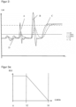
- the control unit 10 comprises a longitudinal load torque control system, which is designed to prevent, on the basis of the signal from the torque sensor and/or other sensors, the operation of the working arm in a way that could endanger the longitudinal and/or lateral instability of the wheel loader 1 . This is done by means of damping, ie filtering of the load moment signal, as shown in FIG figure 2 emerges.
- the solid line LM shows the actual longitudinal load moment while the telescopic wheel loader is being moved on an uneven surface.
- the undamped signal LM is only used when the telescopic wheel loader 1 is stationary or at very low driving speeds of, for example, less than 5 km/h, ie no damping takes place. If, on the other hand, a certain driving speed of, for example, 5 km/h is exceeded, the signal from the torque sensor is dampened.
- the actuating element signal is not manipulated.
- the actuating element signal is interrupted.
- the actuating element signal is damped, which can consist, for example, in the lifting or telescopic cylinder speed being slower for the same deflection of the joystick.
- threshold values S1 and S2 are constant.
- This can take place as a function of the speed and/or as a function of the lifting angle and telescopic radius of the telescopic arm.
- the control algorithm can have a low-pass filter and can be implemented as a first-order PT element, for example.
- the signal LMfilt1 has a damping coefficient of 0.5, for example, and LMfilt2 has a higher damping coefficient, for example 0.7, the maximum value of the filtered signal LMfilt being greater than LMfilt2 for the same load torque peak of LMfilt1.
- the damping coefficient depends on the driving speed v of the working machine, the damping coefficient being determined depending on the driving speed and the damping coefficient being lower at a speed of 0 than at a speed of 5 km/h, for example.
- the damping coefficients are continuously calculated in the control depending on the driving speed.
- any mathematical relationship or look-up table can also be used.
- the actuator signals are manipulated. If the value of the filtered load signal remains below the value of S2, the actuating element signal is calculated only from the actuating element signal (pos. D). If the value of the filtered load signal is in the range between S2 and S1, the actuator signal is reduced so that the speed of the lifting and/or telescoping cylinder is reduced (Pos. A, B (for LMfilt2)). If the value of the filtered load signal LMfilt exceeds the value of S1, the actuating element signal is reduced to zero, so that no movements increasing the load moment are possible (pos. B (for LMfilt1), C).
- FIG 3a shows the extent of the reduction of the actuator signal BS1 depending on LMfilt. Below the threshold S2 there is no impairment of BS1, between S2 and S1 there is a linear drop-off with LMfilt and above S1 there is a shutdown, ie the actuator signal is zero. It is noted that other than a linear relationship between LMfilt and reduced actuator signal (BS1), any mathematical relationship or look-up table may be used.
- an actuating element signal BS2 is generated as a function of the lifting angle signal and telescopic extension signal.
- the for Figure 3a The relationships described apply here accordingly, with the threshold values being marked with S4 and S3.
- threshold values are defined, depending on which the actuating element signals BS2 for lifting/lowering and/or telescoping are not influenced, reduced or interrupted.
- LMfilt an additional dependency on LMfilt can be introduced. This leads, for example, to a greater reduction in BS2 with an increased LMfilt.
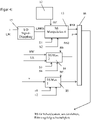
- FIG. 12 shows an embodiment in which not only a single parameter is used to provide the ultimately effective actuator signal from the output.
- Each of the actuator signal manipulation elements 13, 14 and 18 has threshold values.
- LMfilt is used as the input variable for the actuating element signal manipulation element 13, the magnitude of which is determined in the unit 15 as described by signal attenuation based on LM and v.
- the selection/combination logic 16 receives the actuator signal coming from the output of BS manipulation 1 as a BS1 signal, the actuator signal 2 coming from the output of BS manipulation 2 as a BS2 signal and the actuator signal 3 coming from the output of BS manipulation 3 as a BS3 signal fed.
- the module 16 is designed as a minimum module, which means that the smallest of the signals BS1 to BS3 is used to control the valves, cylinders, etc. It is also conceivable that the module is designed in such a way that a weighted new value is formed from the three signals BS1 to BS3, which then represents the output value BS.
- the control element signal BE is formed from the control element 12 and its movement. The same operating element 12 generates the input signal BE of elements 13, 14 and 18.
Landscapes
- Life Sciences & Earth Sciences (AREA)
- Engineering & Computer Science (AREA)
- Geology (AREA)
- Mechanical Engineering (AREA)
- Structural Engineering (AREA)
- Operation Control Of Excavators (AREA)
Claims (14)
- Machine de travail mobile (1), en particulier chargeuse sur roues, avecune structure de véhicule (7),un bras télescopique (3) disposé sur la structure de véhicule (7),un vérin de levage (4) pour lever et abaisser le bras télescopique (3),un vérin télescopique (5) pour rentrer et sortir le bras télescopique (3),un système à couple de charge avec un mécanisme de détection pour déterminer un signal de couple de charge (LM),un capteur de vitesse pour déterminer la vitesse de déplacement (v) de la machine de travail (1), etun élément d'utilisation (12) pour générer un signal d'élément d'utilisation (BE) sur la base duquel un signal d'élément d'actionnement (BS) est généré, qui sert à piloter le ou les vérins (4, 5), dans laquelleest prévue une commande (10) qui est réalisée pour réduire ou interrompre le signal d'élément d'actionnement (BS) au moins par endroits en fonction d'un signal de couple de charge (LM),caractérisée en ce quela commande (10) est conçue en outre pour amortir le signal de couple de charge (LM) en fonction d'au moins un paramètre de la machine de travail (1) et pour réduire ou interrompre le signal d'élément d'actionnement (BS) en fonction du signal de couple de charge amorti (LMfilt), dans laquellel'au moins un paramètre de la machine de travail (1) comprend la vitesse de déplacement (v) de la machine de travail (1).
- Machine de travail (1) selon la revendication 1, caractérisée en ce que la commande (10) est réalisée de telle manière qu'en cas de vitesse de déplacement (v) plus élevée, un amortissement plus intense du signal de couple de charge (LM) est effectué que pour une vitesse de déplacement (v) au contraire plus faible.
- Machine de travail (1) selon l'une quelconque des revendications précédentes, caractérisée en ce que la commande (10) est réalisée de telle manière qu'en cas d'autres valeurs de paramètre plus élevées, un amortissement plus intense du signal de couple de charge (LM) est effectué que pour des valeurs de paramètre au contraire inférieures.
- Machine de travail (1) selon l'une quelconque des revendications précédentes, caractérisée en ce que la commande (10) est réalisée de telle manière que l'amortissement du signal de couple de charge (LM) est effectué au moyen d'un coefficient d'amortissement, qui dépend de l'au moins un paramètre de la machine de travail (1), dans laquelle la dépendance est linéaire ou non ou est enregistrée dans un tableau lisible, dans laquelle de préférence la commande (10) est réalisée pour calculer le coefficient d'amortissement de manière permanente en fonction du ou des paramètres de la machine de travail (1).
- Machine de travail (1) selon l'une quelconque des revendications précédentes, caractérisée en ce que l'amortissement est réalisé de telle manière que le signal de couple de charge amorti (LMfilt) est plus faible au moins par intermittence que le signal de couple de charge (LM) réel et/ou présente une amplitude inférieure au signal de couple de charge (LM) réel.
- Machine de travail (1) selon l'une quelconque des revendications précédentes, caractérisée en ce que la commande (10) est réalisée de telle manière qu'une première valeur de seuil (S2) est prévue et qu'aucune réduction ou interruption du signal d'élément d'actionnement (BS) n'a lieu lorsque la valeur pour le signal de couple de charge amorti (LMfilt) est inférieure à la première valeur de seuil (S2).
- Machine de travail (1) selon l'une quelconque des revendications précédentes, caractérisée en ce que la commande (10) est exécutée de telle manière qu'une deuxième valeur de seuil (S1) est prévue et qu'une interruption du signal d'élément d'actionnement (BS) a lieu lorsque la valeur pour le signal de couple de charge amorti (LMfilt) est supérieure à la deuxième valeur de seuil (S1).
- Machine de travail (1) selon l'une quelconque des revendications précédentes, caractérisée en ce que la commande (10) est exécutée de telle manière qu'une première et une deuxième valeur de seuil sont prévues, et qu'une réduction du signal d'élément d'actionnement (BS) a lieu lorsque la valeur pour le signal de couple de charge amorti (LM) est comprise entre la première et la deuxième valeur de seuil, dans laquelle de préférence la réduction du signal d'élément d'actionnement (BS) augmente au fur et à mesure que le signal de couple de charge amorti (LM) augmente, et/ou la commande (10) est exécutée de telle sorte que la dépendance entre le signal d'élément d'actionnement (BS) et le signal de couple de charge amorti (LM) est au moins par endroits linéaire ou non ou est enregistrée dans un tableau lisible.
- Machine de travail (1) selon l'une quelconque des revendications précédentes, caractérisée en ce que la commande (10) est exécutée de telle manière que d'autres paramètres sont intégrés dans la détermination du signal d'élément d'actionnement (BS), en particulier la vitesse de déplacement (v) de la machine de travail (1) et/ou l'angle de levage (HW) du bras télescopique (3) et/ou la portée (TA) du bras télescopique (3), dans laquelle de préférence la commande (10) est exécutée de telle manière qu'une première valeur de seuil (S1, S3, v1) est prévue et qu'aucune réduction ou interruption du signal d'élément d'actionnement (BS) n'a lieu lorsque la valeur du ou des autres paramètres est inférieure à la première valeur de seuil (S1, S3, v1).
- Machine de travail (1) selon l'une quelconque des revendications précédentes, caractérisée en ce que la commande (10) est exécutée de telle manière qu'une deuxième valeur de seuil (S2, S4, v2) est prévue, et qu'une interruption du signal d'élément d'actionnement (BS) a lieu lorsque la valeur pour le ou les autres paramètres est supérieure à la deuxième valeur de seuil (S2, S4, v2).
- Machine de travail (1) selon l'une quelconque des revendications précédentes, caractérisée en ce que la commande (10) est exécutée de telle manière qu'une première valeur de seuil (S1, S3, v1) et une deuxième valeur de seuil (S2, S4, v2) sont prévues, et qu'une réduction du signal d'élément d'actionnement (BS) a lieu lorsque la valeur du ou des autres paramètres est comprise entre la première valeur de seuil (S1, S3, v1) et la deuxième valeur de seuil (S2, S4, v2), dans laquelle il est prévu de préférence que la réduction du signal d'élément d'actionnement (BS) augmente au fur et à mesure que la valeur du ou des autres paramètres augmente, et/ou la dépendance entre le signal d'élément d'actionnement (BS) et la valeur du ou des autres paramètres est au moins par endroits linéaire ou non ou est enregistrée dans un tableau lisible.
- Machine de travail (1) selon l'une quelconque des revendications précédentes, caractérisée en ce que la commande (10) est exécutée de telle manière que la première valeur de seuil (S1, S3, v1) et/ou la deuxième valeur de seuil (S2, S4, v2) dépendent de la vitesse de déplacement (v) de la machine de travail (1) et/ou de la position de structure de levage et/ou de l'angle de braquage.
- Machine de travail (1) selon l'une quelconque des revendications précédentes, perfectionnée avec les caractéristiques de la revendication 9, caractérisée en ce que la commande (10) est exécutée en tant que module minimum (16) de sorte que le plus petit des signaux d'élément d'actionnement (BS1, BS2, BS3) réduits est pris en compte pour le pilotage du ou des vérins.
- Machine de travail (1) selon l'une quelconque des revendications précédentes, perfectionnée avec les caractéristiques de la revendication 9, caractérisée en ce que la commande (10) est exécutée pour former à partir des signaux d'élément d'actionnement (BS) amenés à celle-ci un signal d'élément d'actionnement pondéré qui est pris en compte pour piloter le ou les vérins.
Applications Claiming Priority (1)
| Application Number | Priority Date | Filing Date | Title |
|---|---|---|---|
| DE102019103620.8A DE102019103620A1 (de) | 2019-02-13 | 2019-02-13 | Mobile Arbeitsmaschine |
Publications (2)
| Publication Number | Publication Date |
|---|---|
| EP3696137A1 EP3696137A1 (fr) | 2020-08-19 |
| EP3696137B1 true EP3696137B1 (fr) | 2023-03-29 |
Family
ID=69701051
Family Applications (1)
| Application Number | Title | Priority Date | Filing Date |
|---|---|---|---|
| EP20157158.5A Active EP3696137B1 (fr) | 2019-02-13 | 2020-02-13 | Machine de travail mobile |
Country Status (2)
| Country | Link |
|---|---|
| EP (1) | EP3696137B1 (fr) |
| DE (1) | DE102019103620A1 (fr) |
Families Citing this family (3)
| Publication number | Priority date | Publication date | Assignee | Title |
|---|---|---|---|---|
| DE102021121163A1 (de) | 2021-08-13 | 2023-02-16 | Danfoss Power Solutions Gmbh & Co. Ohg | Verbesserter Teleskoplader |
| DE102021128642A1 (de) | 2021-11-03 | 2023-05-04 | Weidemann GmbH | Baumaschine oder landwirtschaftliche Maschine |
| DE102021128580A1 (de) | 2021-11-03 | 2023-05-04 | Kramer-Werke Gmbh | Baumaschine oder landwirtschaftliche Maschine |
Family Cites Families (4)
| Publication number | Priority date | Publication date | Assignee | Title |
|---|---|---|---|---|
| US7797122B2 (en) * | 2006-08-09 | 2010-09-14 | Incova Technologies, Inc. | Electrohydraulic valve control circuit with velocity fault detection and rectification |
| GB2471134B (en) * | 2009-06-19 | 2012-10-10 | Bamford Excavators Ltd | Speed sensitive longitudinal load moment control of a working machine |
| US10071894B2 (en) * | 2015-08-03 | 2018-09-11 | The Raymond Corporation | Oscillation damping for a material handling vehicle |
| US10549970B2 (en) * | 2017-08-02 | 2020-02-04 | Jlg Industries, Inc. | Telehandler with cantilever boom mounting |
-
2019
- 2019-02-13 DE DE102019103620.8A patent/DE102019103620A1/de not_active Withdrawn
-
2020
- 2020-02-13 EP EP20157158.5A patent/EP3696137B1/fr active Active
Also Published As
| Publication number | Publication date |
|---|---|
| DE102019103620A1 (de) | 2020-08-13 |
| EP3696137A1 (fr) | 2020-08-19 |
Similar Documents
| Publication | Publication Date | Title |
|---|---|---|
| EP3696137B1 (fr) | Machine de travail mobile | |
| DE102008020595B4 (de) | Verfahren zur Schwingungsdämpfung bei Flurförderzeugen | |
| EP2378053B1 (fr) | Machine de génie civil doté d'une unité de calcul pour déterminer une zone de réglage | |
| EP2364877B1 (fr) | Surveillance d'un état de basculement | |
| EP2722441B1 (fr) | Engin automoteur et procédé de fonctionnement d'un engin automoteur | |
| EP3067468B1 (fr) | Engin de construction automoteur et procédé de fonctionnement de celui-ci | |
| WO2005090694A1 (fr) | Procede et dispositif d'amortissement de mouvement de machines de construction | |
| DE102019202664A1 (de) | Hydraulische Minderung von Stabilitätskontrolle und Kalibrierung | |
| EP3371383B1 (fr) | Procédé et système de stabilisation d'engin de chantier | |
| DE102020003044A1 (de) | Baumaschine und verfahren zur erhöhung der standsicherheit einer baumaschine | |
| DE102005012004A1 (de) | Flurförderzeug mit erhöhter statischer/quasistatischer und dynamischer Kippstabilität | |
| EP3067257B1 (fr) | Dispositif et procede de determination de la repartition de la pression au sol pour une machine de travail mobile | |
| EP3532425B1 (fr) | Dispositif de compensation de traction oblique dans des grues | |
| EP2378054A1 (fr) | Dispositif de sécurité pour un engin | |
| EP2733036A2 (fr) | Machine mobile comprenant une installation de chargement | |
| EP2733110B1 (fr) | Machine mobile avec un dispositif de chargement, la machine peut fonctionner dans deux modes de commande d'urgence | |
| EP3115332B1 (fr) | Procede de commande d'un chariot de manutention | |
| DE102008020593B4 (de) | Verfahren zur Schwingungsdämpfung bei Flurförderzeugen | |
| DE102012022404A1 (de) | Maschine mit Ladeanlage | |
| DE102021203337B4 (de) | Steuereinheit für eine mobile Arbeitsmaschine, mobile Arbeitsmaschine damit, und Verfahren zur Steuerung der Arbeitsmaschine | |
| DE102006012982A1 (de) | Schubmaststapler mit einem Hubgerüst | |
| EP4242160A1 (fr) | Machine de construction ou machine agricole | |
| EP4516718B1 (fr) | Procédé de surveillance de charge de support d'une grue dotée de deux moyens de réception de charge | |
| EP3301065B1 (fr) | Procédé de commande d'un chariot de manutention doté d'un élément de commande ainsi qu'un chariot de manutention | |
| DE102017202009A1 (de) | Kran |
Legal Events
| Date | Code | Title | Description |
|---|---|---|---|
| PUAI | Public reference made under article 153(3) epc to a published international application that has entered the european phase |
Free format text: ORIGINAL CODE: 0009012 |
|
| STAA | Information on the status of an ep patent application or granted ep patent |
Free format text: STATUS: THE APPLICATION HAS BEEN PUBLISHED |
|
| AK | Designated contracting states |
Kind code of ref document: A1 Designated state(s): AL AT BE BG CH CY CZ DE DK EE ES FI FR GB GR HR HU IE IS IT LI LT LU LV MC MK MT NL NO PL PT RO RS SE SI SK SM TR |
|
| AX | Request for extension of the european patent |
Extension state: BA ME |
|
| STAA | Information on the status of an ep patent application or granted ep patent |
Free format text: STATUS: REQUEST FOR EXAMINATION WAS MADE |
|
| 17P | Request for examination filed |
Effective date: 20210219 |
|
| GRAP | Despatch of communication of intention to grant a patent |
Free format text: ORIGINAL CODE: EPIDOSNIGR1 |
|
| STAA | Information on the status of an ep patent application or granted ep patent |
Free format text: STATUS: GRANT OF PATENT IS INTENDED |
|
| INTG | Intention to grant announced |
Effective date: 20221014 |
|
| GRAS | Grant fee paid |
Free format text: ORIGINAL CODE: EPIDOSNIGR3 |
|
| RAP3 | Party data changed (applicant data changed or rights of an application transferred) |
Owner name: LIEBHERR-WERK BISCHOFSHOFEN GMBH |
|
| GRAA | (expected) grant |
Free format text: ORIGINAL CODE: 0009210 |
|
| STAA | Information on the status of an ep patent application or granted ep patent |
Free format text: STATUS: THE PATENT HAS BEEN GRANTED |
|
| AK | Designated contracting states |
Kind code of ref document: B1 Designated state(s): AL AT BE BG CH CY CZ DE DK EE ES FI FR GB GR HR HU IE IS IT LI LT LU LV MC MK MT NL NO PL PT RO RS SE SI SK SM TR |
|
| REG | Reference to a national code |
Ref country code: CH Ref legal event code: EP |
|
| REG | Reference to a national code |
Ref country code: DE Ref legal event code: R096 Ref document number: 502020002836 Country of ref document: DE |
|
| REG | Reference to a national code |
Ref country code: AT Ref legal event code: REF Ref document number: 1556560 Country of ref document: AT Kind code of ref document: T Effective date: 20230415 |
|
| REG | Reference to a national code |
Ref country code: IE Ref legal event code: FG4D Free format text: LANGUAGE OF EP DOCUMENT: GERMAN |
|
| REG | Reference to a national code |
Ref country code: LT Ref legal event code: MG9D |
|
| P01 | Opt-out of the competence of the unified patent court (upc) registered |
Effective date: 20230608 |
|
| PG25 | Lapsed in a contracting state [announced via postgrant information from national office to epo] |
Ref country code: RS Free format text: LAPSE BECAUSE OF FAILURE TO SUBMIT A TRANSLATION OF THE DESCRIPTION OR TO PAY THE FEE WITHIN THE PRESCRIBED TIME-LIMIT Effective date: 20230329 Ref country code: NO Free format text: LAPSE BECAUSE OF FAILURE TO SUBMIT A TRANSLATION OF THE DESCRIPTION OR TO PAY THE FEE WITHIN THE PRESCRIBED TIME-LIMIT Effective date: 20230629 Ref country code: LV Free format text: LAPSE BECAUSE OF FAILURE TO SUBMIT A TRANSLATION OF THE DESCRIPTION OR TO PAY THE FEE WITHIN THE PRESCRIBED TIME-LIMIT Effective date: 20230329 Ref country code: LT Free format text: LAPSE BECAUSE OF FAILURE TO SUBMIT A TRANSLATION OF THE DESCRIPTION OR TO PAY THE FEE WITHIN THE PRESCRIBED TIME-LIMIT Effective date: 20230329 Ref country code: HR Free format text: LAPSE BECAUSE OF FAILURE TO SUBMIT A TRANSLATION OF THE DESCRIPTION OR TO PAY THE FEE WITHIN THE PRESCRIBED TIME-LIMIT Effective date: 20230329 |
|
| REG | Reference to a national code |
Ref country code: NL Ref legal event code: MP Effective date: 20230329 |
|
| PG25 | Lapsed in a contracting state [announced via postgrant information from national office to epo] |
Ref country code: SE Free format text: LAPSE BECAUSE OF FAILURE TO SUBMIT A TRANSLATION OF THE DESCRIPTION OR TO PAY THE FEE WITHIN THE PRESCRIBED TIME-LIMIT Effective date: 20230329 Ref country code: NL Free format text: LAPSE BECAUSE OF FAILURE TO SUBMIT A TRANSLATION OF THE DESCRIPTION OR TO PAY THE FEE WITHIN THE PRESCRIBED TIME-LIMIT Effective date: 20230329 Ref country code: GR Free format text: LAPSE BECAUSE OF FAILURE TO SUBMIT A TRANSLATION OF THE DESCRIPTION OR TO PAY THE FEE WITHIN THE PRESCRIBED TIME-LIMIT Effective date: 20230630 Ref country code: FI Free format text: LAPSE BECAUSE OF FAILURE TO SUBMIT A TRANSLATION OF THE DESCRIPTION OR TO PAY THE FEE WITHIN THE PRESCRIBED TIME-LIMIT Effective date: 20230329 |
|
| PG25 | Lapsed in a contracting state [announced via postgrant information from national office to epo] |
Ref country code: SM Free format text: LAPSE BECAUSE OF FAILURE TO SUBMIT A TRANSLATION OF THE DESCRIPTION OR TO PAY THE FEE WITHIN THE PRESCRIBED TIME-LIMIT Effective date: 20230329 Ref country code: RO Free format text: LAPSE BECAUSE OF FAILURE TO SUBMIT A TRANSLATION OF THE DESCRIPTION OR TO PAY THE FEE WITHIN THE PRESCRIBED TIME-LIMIT Effective date: 20230329 Ref country code: PT Free format text: LAPSE BECAUSE OF FAILURE TO SUBMIT A TRANSLATION OF THE DESCRIPTION OR TO PAY THE FEE WITHIN THE PRESCRIBED TIME-LIMIT Effective date: 20230731 Ref country code: ES Free format text: LAPSE BECAUSE OF FAILURE TO SUBMIT A TRANSLATION OF THE DESCRIPTION OR TO PAY THE FEE WITHIN THE PRESCRIBED TIME-LIMIT Effective date: 20230329 Ref country code: EE Free format text: LAPSE BECAUSE OF FAILURE TO SUBMIT A TRANSLATION OF THE DESCRIPTION OR TO PAY THE FEE WITHIN THE PRESCRIBED TIME-LIMIT Effective date: 20230329 |
|
| PG25 | Lapsed in a contracting state [announced via postgrant information from national office to epo] |
Ref country code: SK Free format text: LAPSE BECAUSE OF FAILURE TO SUBMIT A TRANSLATION OF THE DESCRIPTION OR TO PAY THE FEE WITHIN THE PRESCRIBED TIME-LIMIT Effective date: 20230329 Ref country code: PL Free format text: LAPSE BECAUSE OF FAILURE TO SUBMIT A TRANSLATION OF THE DESCRIPTION OR TO PAY THE FEE WITHIN THE PRESCRIBED TIME-LIMIT Effective date: 20230329 Ref country code: IS Free format text: LAPSE BECAUSE OF FAILURE TO SUBMIT A TRANSLATION OF THE DESCRIPTION OR TO PAY THE FEE WITHIN THE PRESCRIBED TIME-LIMIT Effective date: 20230729 |
|
| REG | Reference to a national code |
Ref country code: DE Ref legal event code: R097 Ref document number: 502020002836 Country of ref document: DE |
|
| PG25 | Lapsed in a contracting state [announced via postgrant information from national office to epo] |
Ref country code: DK Free format text: LAPSE BECAUSE OF FAILURE TO SUBMIT A TRANSLATION OF THE DESCRIPTION OR TO PAY THE FEE WITHIN THE PRESCRIBED TIME-LIMIT Effective date: 20230329 Ref country code: CZ Free format text: LAPSE BECAUSE OF FAILURE TO SUBMIT A TRANSLATION OF THE DESCRIPTION OR TO PAY THE FEE WITHIN THE PRESCRIBED TIME-LIMIT Effective date: 20230329 |
|
| PLBE | No opposition filed within time limit |
Free format text: ORIGINAL CODE: 0009261 |
|
| STAA | Information on the status of an ep patent application or granted ep patent |
Free format text: STATUS: NO OPPOSITION FILED WITHIN TIME LIMIT |
|
| 26N | No opposition filed |
Effective date: 20240103 |
|
| PG25 | Lapsed in a contracting state [announced via postgrant information from national office to epo] |
Ref country code: SI Free format text: LAPSE BECAUSE OF FAILURE TO SUBMIT A TRANSLATION OF THE DESCRIPTION OR TO PAY THE FEE WITHIN THE PRESCRIBED TIME-LIMIT Effective date: 20230329 |
|
| PG25 | Lapsed in a contracting state [announced via postgrant information from national office to epo] |
Ref country code: SI Free format text: LAPSE BECAUSE OF FAILURE TO SUBMIT A TRANSLATION OF THE DESCRIPTION OR TO PAY THE FEE WITHIN THE PRESCRIBED TIME-LIMIT Effective date: 20230329 Ref country code: IT Free format text: LAPSE BECAUSE OF FAILURE TO SUBMIT A TRANSLATION OF THE DESCRIPTION OR TO PAY THE FEE WITHIN THE PRESCRIBED TIME-LIMIT Effective date: 20230329 |
|
| PG25 | Lapsed in a contracting state [announced via postgrant information from national office to epo] |
Ref country code: MC Free format text: LAPSE BECAUSE OF FAILURE TO SUBMIT A TRANSLATION OF THE DESCRIPTION OR TO PAY THE FEE WITHIN THE PRESCRIBED TIME-LIMIT Effective date: 20230329 |
|
| PG25 | Lapsed in a contracting state [announced via postgrant information from national office to epo] |
Ref country code: LU Free format text: LAPSE BECAUSE OF NON-PAYMENT OF DUE FEES Effective date: 20240213 |
|
| PGFP | Annual fee paid to national office [announced via postgrant information from national office to epo] |
Ref country code: CH Payment date: 20240704 Year of fee payment: 5 |
|
| PG25 | Lapsed in a contracting state [announced via postgrant information from national office to epo] |
Ref country code: LU Free format text: LAPSE BECAUSE OF NON-PAYMENT OF DUE FEES Effective date: 20240213 |
|
| PG25 | Lapsed in a contracting state [announced via postgrant information from national office to epo] |
Ref country code: BG Free format text: LAPSE BECAUSE OF FAILURE TO SUBMIT A TRANSLATION OF THE DESCRIPTION OR TO PAY THE FEE WITHIN THE PRESCRIBED TIME-LIMIT Effective date: 20230329 |
|
| PG25 | Lapsed in a contracting state [announced via postgrant information from national office to epo] |
Ref country code: BG Free format text: LAPSE BECAUSE OF FAILURE TO SUBMIT A TRANSLATION OF THE DESCRIPTION OR TO PAY THE FEE WITHIN THE PRESCRIBED TIME-LIMIT Effective date: 20230329 |
|
| REG | Reference to a national code |
Ref country code: BE Ref legal event code: MM Effective date: 20240229 |
|
| PG25 | Lapsed in a contracting state [announced via postgrant information from national office to epo] |
Ref country code: BE Free format text: LAPSE BECAUSE OF NON-PAYMENT OF DUE FEES Effective date: 20240229 |
|
| PG25 | Lapsed in a contracting state [announced via postgrant information from national office to epo] |
Ref country code: IE Free format text: LAPSE BECAUSE OF NON-PAYMENT OF DUE FEES Effective date: 20240213 |
|
| PG25 | Lapsed in a contracting state [announced via postgrant information from national office to epo] |
Ref country code: IE Free format text: LAPSE BECAUSE OF NON-PAYMENT OF DUE FEES Effective date: 20240213 Ref country code: BE Free format text: LAPSE BECAUSE OF NON-PAYMENT OF DUE FEES Effective date: 20240229 |
|
| PG25 | Lapsed in a contracting state [announced via postgrant information from national office to epo] |
Ref country code: CY Free format text: LAPSE BECAUSE OF FAILURE TO SUBMIT A TRANSLATION OF THE DESCRIPTION OR TO PAY THE FEE WITHIN THE PRESCRIBED TIME-LIMIT; INVALID AB INITIO Effective date: 20200213 |
|
| PG25 | Lapsed in a contracting state [announced via postgrant information from national office to epo] |
Ref country code: HU Free format text: LAPSE BECAUSE OF FAILURE TO SUBMIT A TRANSLATION OF THE DESCRIPTION OR TO PAY THE FEE WITHIN THE PRESCRIBED TIME-LIMIT; INVALID AB INITIO Effective date: 20200213 |
|
| REG | Reference to a national code |
Ref country code: CH Ref legal event code: PL |
|
| PG25 | Lapsed in a contracting state [announced via postgrant information from national office to epo] |
Ref country code: CH Free format text: LAPSE BECAUSE OF NON-PAYMENT OF DUE FEES Effective date: 20250228 |
|
| PG25 | Lapsed in a contracting state [announced via postgrant information from national office to epo] |
Ref country code: TR Free format text: LAPSE BECAUSE OF FAILURE TO SUBMIT A TRANSLATION OF THE DESCRIPTION OR TO PAY THE FEE WITHIN THE PRESCRIBED TIME-LIMIT Effective date: 20230329 |
|
| PGFP | Annual fee paid to national office [announced via postgrant information from national office to epo] |
Ref country code: GB Payment date: 20260226 Year of fee payment: 7 |
|
| PGFP | Annual fee paid to national office [announced via postgrant information from national office to epo] |
Ref country code: DE Payment date: 20260303 Year of fee payment: 7 |
|
| PGFP | Annual fee paid to national office [announced via postgrant information from national office to epo] |
Ref country code: AT Payment date: 20260223 Year of fee payment: 7 |
|
| PGFP | Annual fee paid to national office [announced via postgrant information from national office to epo] |
Ref country code: FR Payment date: 20260225 Year of fee payment: 7 |