EP2378053B1 - Machine de génie civil doté d'une unité de calcul pour déterminer une zone de réglage - Google Patents
Machine de génie civil doté d'une unité de calcul pour déterminer une zone de réglage Download PDFInfo
- Publication number
- EP2378053B1 EP2378053B1 EP10004084.9A EP10004084A EP2378053B1 EP 2378053 B1 EP2378053 B1 EP 2378053B1 EP 10004084 A EP10004084 A EP 10004084A EP 2378053 B1 EP2378053 B1 EP 2378053B1
- Authority
- EP
- European Patent Office
- Prior art keywords
- detecting
- unit
- construction machine
- mast
- detecting means
- Prior art date
- Legal status (The legal status is an assumption and is not a legal conclusion. Google has not performed a legal analysis and makes no representation as to the accuracy of the status listed.)
- Active
Links
Images
Classifications
-
- E—FIXED CONSTRUCTIONS
- E21—EARTH OR ROCK DRILLING; MINING
- E21B—EARTH OR ROCK DRILLING; OBTAINING OIL, GAS, WATER, SOLUBLE OR MELTABLE MATERIALS OR A SLURRY OF MINERALS FROM WELLS
- E21B7/00—Special methods or apparatus for drilling
- E21B7/003—Drilling with mechanical conveying means
- E21B7/005—Drilling with mechanical conveying means with helical conveying means
-
- E—FIXED CONSTRUCTIONS
- E21—EARTH OR ROCK DRILLING; MINING
- E21B—EARTH OR ROCK DRILLING; OBTAINING OIL, GAS, WATER, SOLUBLE OR MELTABLE MATERIALS OR A SLURRY OF MINERALS FROM WELLS
- E21B15/00—Supports for the drilling machine, e.g. derricks or masts
-
- E—FIXED CONSTRUCTIONS
- E21—EARTH OR ROCK DRILLING; MINING
- E21B—EARTH OR ROCK DRILLING; OBTAINING OIL, GAS, WATER, SOLUBLE OR MELTABLE MATERIALS OR A SLURRY OF MINERALS FROM WELLS
- E21B41/00—Equipment or details not covered by groups E21B15/00 - E21B40/00
- E21B41/0021—Safety devices, e.g. for preventing small objects from falling into the borehole
-
- E—FIXED CONSTRUCTIONS
- E21—EARTH OR ROCK DRILLING; MINING
- E21B—EARTH OR ROCK DRILLING; OBTAINING OIL, GAS, WATER, SOLUBLE OR MELTABLE MATERIALS OR A SLURRY OF MINERALS FROM WELLS
- E21B44/00—Automatic control systems specially adapted for drilling operations, i.e. self-operating systems which function to carry out or modify a drilling operation without intervention of a human operator, e.g. computer-controlled drilling systems; Systems specially adapted for monitoring a plurality of drilling variables or conditions
-
- E—FIXED CONSTRUCTIONS
- E21—EARTH OR ROCK DRILLING; MINING
- E21B—EARTH OR ROCK DRILLING; OBTAINING OIL, GAS, WATER, SOLUBLE OR MELTABLE MATERIALS OR A SLURRY OF MINERALS FROM WELLS
- E21B7/00—Special methods or apparatus for drilling
- E21B7/02—Drilling rigs characterised by means for land transport with their own drive, e.g. skid mounting or wheel mounting
- E21B7/022—Control of the drilling operation; Hydraulic or pneumatic means for activation or operation
Definitions
- the invention relates to a civil engineering machine according to claim 1 and to a method for operating a civil engineering machine according to claim 10.
- tilting moments can occur on the civil engineering machinery.
- Such tilting moments can be caused statically, for example by spreading loads, but also dynamically, for example by centrifugal forces.
- the US-A-4511974 discloses a forklift with a height-adjustable and tiltable lifting fork. By means of a computer unit, an adjustment range can be determined on the basis of detected status data.
- the object of the invention is to provide a civil engineering machine and a method for this, which allow a particularly safe operation with a particularly high operating reliability, in particular with regard to the tipping safety.
- the object is achieved by a civil engineering machine with the features of claim 1. Preferred embodiments are given in the dependent claims. Furthermore, the object is achieved by a method having the features of claim 10.
- a civil engineering machine is provided with a carrier unit, an actuating unit, which is adjustable relative to the carrier unit, at least one sensor for detecting state data of the civil engineering machine, and a computer unit, by which at least based on the detected state data an adjustment of the operating unit can be determined, in which the actuating unit is adjustable at a predetermined tilting security of the civil engineering machine.
- the invention is based on the recognition that when adjusting a heavy actuator unit relative to the carrier unit, which carries the actuator unit, center of gravity shifts can occur, which are associated with corresponding variable tilting moments.
- a computer unit determines an adjustment range in which the actuating unit can be moved safely relative to its carrier unit.
- the safe setting range can be distinguished, for example, by the fact that a predetermined tilting safety factor is maintained in its interior.
- corresponding characteristic fields or tables can be stored in the evaluation unit, for example.
- the determination of the adjustment range is carried out depending on the state data of the civil engineering machine, that is, the computer unit can take into account in the overall consideration that the tendency to tilt is determined not only by the projection of the actuator, but is also influenced by other factors, such as the load on the Actuator or the dynamic state of the civil engineering machine. Therefore, the state data may, for example, be data relating to the diameter of a drill pipe held by the actuation unit, which again influences the tilting moment via the associated mass of the drill pipe.
- the civil engineering machine may in particular be an earth boring device.
- the operating unit may be, for example, the drill drive for a Erdbohrtechnikmaschine, and the carrier unit of the undercarriage of the drill.
- the position of the actuating unit within the adjustment range can be determined by the computer unit, and a signal can be emitted when a limit of the adjustment range is reached.
- the actual position of the actuating unit is related to the calculated adjustment range by the computer unit, so that it can be directly assessed whether tilt-safe operation is present or whether there is a danger of tipping.
- the signal which is emitted when the limit of the adjustment range is reached it may be, for example, an operator signal, so for example, an acoustic or optical signal that can be perceived by an operator of the civil engineering machine.
- the operator is thus able to detect the approach to a dangerous area, so that the operator can take appropriate countermeasures.
- a control signal for the actuating unit can be emitted as a signal.
- the computer unit can automatically hold the actuator in the safe adjustment range, so that a particularly reliable operation is given.
- the invention can be used, in particular, in mobile civil engineering machines, since it is often necessary to pay particular attention to tipping safety. Accordingly, it is expedient that the carrier unit has a chassis.
- the carrier unit may be an undercarriage of the civil engineering machine.
- the actuating unit has at least one civil engineering tool, in particular a drilling tool.
- the actuating unit can be designed, for example, as a rotary drilling drive and / or vibrating drilling drive.
- the actuating unit relative to the support unit about a vertical axis is pivotable and radially adjustable to the vertical axis.
- Under the vertical axis can be understood in particular an at least approximately vertical axis.
- the actuating unit embodied as a drill drive is arranged on a mast which is radially adjustable relative to an uppercarriage, which in turn is pivotable relative to the carrier unit formed as an undercarriage.
- the transducer according to the invention can detect the state data by physical measurement. It may also be advantageous for at least one sensor to be provided which records status data which is entered manually by the operator. For example, it may be provided that the operator receives a selection menu of possible drill pipe diameters, for example 880 mm or 1300 mm, or the drill pipe diameter is detected automatically. According to the input, the computer unit then determines different adjustment ranges, wherein the adjustment range for larger drill pipe diameter and thus heavier drill pipe will be regularly smaller than for a smaller diameter. If a pickup is provided for detecting manually entered status data, it is advantageous that the computer unit has a memory device for storing the manually entered data. This will provide documentation to help you determine if the data entered was correct in the event of possible failure.
- a further preferred embodiment of the invention consists in that an operator-actuatable handling assistance switching device is provided, which is in signal communication with the computer unit, wherein the computer unit is adapted to modify the adjustment range as a function of a switching state of the handling assistance switching device.
- This embodiment takes into account that different operating modes frequently occur on the civil engineering machine, which require different overturning safety considerations. For example, in a drilling operation of a drill often additional forces on the drilling tool, which can increase the tendency to tilt, or it is working with angled mast, which can also increase the tendency to tilt. Therefore, a limited adjustment range can be determined in the drilling operation by the computer unit.
- the handling assistance switching device can be realized, for example, via a switch or via a touchscreen, at which the operator specifies whether a working operation, in particular drilling operation, or whether a handling operation is provided.
- the handling assistance switching device expediently has a memory device which is set up to store the choice of the operator on the handling assistance switching device.
- the extension of the adjustment range in handling mode requires that other operating parameters of the civil engineering machine and the associated overturning moments be limited.
- the extended adjustment range in the Handling mode be justified only if the winching forces of a main winch, an auxiliary winch or a feed winch are below an allowable limit.
- the handling assistance switching device may have a display which indicates to the operator the limits of these operating parameters when the handling mode is selected on the handling assistance switching device. For example, the permissible winch forces can be displayed on a display.
- a limiting unit which is set up to limit at least one operating parameter of the civil engineering machine as a function of the switching state of the handling assistance switching device.
- the critical operating parameters can be automatically limited when the handling mode is selected on the handling assistance switching device.
- the at least one operating parameter which is limited and / or displayed to the operator, may in particular be wind tensile forces. Accordingly, it may be provided that the limit purity reduces the torque of a feed winch and shuts off an auxiliary winch when handling mode is selected.
- the handling assistance switching device comprises a protective device which prevents the effect of an actuation of the handling assistance switching device when at least one operating parameter of the civil engineering machine is outside a predetermined range.
- the effect of the operation of the handling assistance switching device can be prevented if at least one operating parameter is atypical for the handling operation, and thus an extension of the adjustment range is not justified.
- the at least one operating parameter of the civil engineering machine whose limits are displayed to the operator, which is limited by means of the limiting unit and / or which is taken into account by the safety device, may in particular be a superstructure speed and / or a mast tilt.
- Inventive civil engineering machines have an upper carriage, which is arranged rotatably about a vertical axis on the carrier unit, and on which a mast is arranged, which is the actuating unit wearing. If the superstructure together with the actuating unit is rotated about the vertical axis relative to the carrier unit, then centrifugal forces can occur which increase the tendency to tilt dynamically. Therefore, a manual or automatic limitation of the superstructure speed may be advantageous.
- the mast inclination of the mast relative to the superstructure can influence the tendency to tilt, so that a limitation of the mast tilt with regard to the tipping safety can be advantageous.
- the at least one operating parameter whose limits are displayed, which is limited by means of the limiting unit and / or which is taken into account by the protective device, may also be a rotation angle of the superstructure relative to the undercarriage, since a mobile undercarriage is often not in all spatial directions equal tip over.
- the state data on the basis of which the adjustment range is determined by the computer unit, may in particular be a weight force on the actuating unit.
- the tube length can be taken into account on the actuator, because the longer the drill pipe hanging on the actuator, the greater is often the tendency to tilt.
- At least one sensor is provided for detecting a position of a mast support jib. Because the position of the mast support arm, which connects the mast with the superstructure, is a measure of the radial position of the mast and thus the position of the actuating unit relative to the superstructure, and thus determines the overturning moment.
- At least one sensor for detecting a rotational angle of the upper carriage is provided. Because the carrier unit is often not equal tilt stability in all directions. Thus, the upper carriage rotation angle of the upper carriage relative to the carrier unit, in particular about a vertical axis, also gives indications of overturning safety.
- At least one sensor is provided for detecting a tensile and / or compressive force in a feed system for a carriage.
- a carriage feed system may, in particular, be understood to mean a system which drives the operating unit relative to the mast in the vertical direction shifts. The tensile and / or compressive force acting there can likewise influence the overturning moment.
- At least one sensor is provided for detecting a tensile force in a main cable.
- a corresponding main rope may carry a drill pipe extending on the actuator unit.
- At least one sensor is provided for detecting a tensile force in an auxiliary rope.
- an auxiliary rope which can be used for example in the assembly of a drill pipe, can also cause tilting moments.
- a further embodiment is that at least one sensor is provided for detecting at least one inlet angle of the auxiliary rope, because the inlet angle can also influence the tilting moment caused by the auxiliary rope.
- the entry angle is determined in two spatial levels.
- a further preferred embodiment of the invention consists in that at least one sensor is provided for detecting at least one angle of inclination of the carrier unit.
- the inclination angle is determined in two spatial levels. The angle of inclination of the undercarriage can also influence the tilting moments.
- At least one receptacle is provided for detecting at least one inclination angle of the mast.
- the tilt angle of the mast can be understood in particular the inclination angle of the mast relative to the superstructure. This angle can also influence the tilting moments.
- the inclination angle is determined in two spatial levels.
- At least one sensor is provided for detecting a side end position of the auxiliary cable.
- the load applied to the auxiliary cable may be subject to pendulum movements, which likewise contribute to the overturning moment.
- the sensor for detecting a cable end position of the auxiliary cable can be designed in particular as a sensor for detecting the Abspulwinkels a drum for the auxiliary rope.
- At least one sensor is provided for detecting a wind speed. This takes into account that wind loads can also have a tilting moment increasing effect.
- At least one sensor is provided for detecting a rotational speed of the upper carriage.
- At least one sensor is provided for detecting a cable end position of a feed cable. Because the position of the feed rope points to the position of the actuator and thus in turn to the relevant for the tilt safety center of gravity.
- At least one sensor is provided for detecting a longitudinal position of the main cable. By detecting the end position of the main rope center of gravity coordinates can be determined, which determine the tipping moment.
- the state data is thus advantageous for the state data to be the tensile and / or pressure force in the feed system for the carriage, the tensile force in the main cable, the tensile force in the auxiliary cable, the at least one entry angle of the auxiliary cable, the at least one inclination angle of the carrier unit, the at least one inclination angle of the mast, the Seilendposition the auxiliary rope, the wind speed, the rotational speed of the upper carriage, the Seilendposition the feed rope and / or the Seilendposition of the main rope concern.
- a further preferred embodiment of the invention is that a display device is provided, with which the adjustment can be displayed together with the current position of the actuator unit, and that the display device is adapted to represent the adjustment and the current position in a common position sketch.
- the display device is set up for the adjustment range by a color Highlighting. According to this embodiment, the operator is visually displayed the safe adjustment range as well as the actual instantaneous position of the actuation unit with respect to this adjustment range. As a result, the operator is able to intuitively detect the tilting security situation.
- the invention also relates to a method for operating the civil engineering machine according to the invention, comprising a carrier unit, an actuating unit which is adjustable relative to the carrier unit, at least one sensor for detecting state data of the civil engineering machine, and a computer unit, wherein it is provided by the computer unit based on the detected state data is determined at least one adjustment range of the actuating unit, in which the actuating unit can be adjusted at a predetermined tilting safety of the civil engineering machine.
- the embodiments explained in connection with the civil engineering machine according to the invention can also be used in connection with the method according to the invention, whereby the advantages explained in connection with the civil engineering machine can be achieved.
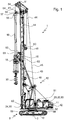
- a civil engineering machine according to the invention is in Fig. 1 shown.
- the civil engineering machine 1 is designed as a mobile Erdbohr réelle. It has a carrier unit 10 embodied as an undercarriage with a chassis 9 designed as a crawler track chassis. On this support unit 10, an upper carriage 11 of the civil engineering machine 1 is arranged. The uppercarriage 11 is provided pivotally about the vertical axis 3 on the carrier unit 10.
- mast support beams 12 are arranged, which carry a mast 14 and connect to the superstructure 11.
- the mast support beams 12 are provided pivotable about horizontally extending axes. By pivoting the mast support arm 12, the mast 14 can be radially adjusted with respect to the upper carriage 11 and thus the carrier unit 10.
- a carriage 15 is arranged vertically displaceable.
- an actuating unit 18 is provided which forms a rotary drilling drive.
- the actuating unit 18 has a driven civil engineering tool 19, 20, which is formed by a drill pipe 19 with screw drill 20 arranged on the underside.
- the drill pipe 19 may be formed in particular as a Kelly bar.
- the actuating unit 18 By pivoting the superstructure 11 relative to the carrier unit 10, the actuating unit 18 can also be pivoted relative to the carrier unit 10 about the vertical axis 3. By pivoting the mast support arm 12, the actuating unit 18 can be pivoted relative to the vertical axis 3 radially to the carrier unit 10.
- the drill pipe 19 of the civil engineering tool is suspended on a main cable 41, which extends around the head of the mast 14 around.
- a main winch 42 is provided in the rear area of the uppercarriage 11 or on the mast 14.
- an auxiliary cable 44 is guided around the mast 14, which can be actuated by means of an auxiliary cable winch 45.
- This auxiliary cable 44 can be used, for example, when the drill string 19 is mounted on the civil engineering machine 1.
- a feed system with a feed winch 48 and a running around the mast 14 feed cable 49 is provided, which is fixed to the carriage 15.
- a computer unit 23 is provided which is in signal communication with a series of receivers 51 to 64 described in more detail below. Based on the state data acquired by the sensors 51 to 64, this computer unit 23 can be used to ascertain an adjustment range of the actuating unit 18 in which the actuating unit 18 is tilt-adjustable, in particular movable radially to the vertical axis 3 and pivotable about the vertical axis 3.
- a display device 24 is provided in the operator's cab of the upper carriage 11, which is in signal communication with the computer unit 23, and with which the adjustment range can be displayed together with the actual current position of the actuator unit 18.
- the display device 24, for example have a display.
- a handling assistance switching device 30 On the display device 24 and a handling assistance switching device 30 is arranged, which can be realized for example by a touch screen. By means of this handling assistance switching device 30, the operator can enter whether a drilling operation or a handling operation is provided.
- the handling assistance switching device 30 is in signal connection with the computer unit 23, so that the computer unit 23 can vary the tilt-proof adjustment range depending on the operating mode.
- a limiter unit 32 is also provided, which is in signal communication with the computer unit 23, and which limits at least one operating parameter of the civil engineering machine 1 as a function of the switching state of the handling assistance switching device 30.
- the limiter unit 32 may limit the pivoting speed of the uppercarriage 11 about the vertical axis 3 relative to the carrier unit 10, that is to the undercarriage, when the handling mode is selected, and cancel this limitation in the drilling mode.
- the limiter unit 32 may also limit the radial position of the actuator unit 18 by limiting the deflection of the mast support beams 12.
- a protective device 33 is provided on the civil engineering machine 1, which is in signal communication with the handling assistance switching device 30 and / or with the display device 24, and which inhibits selection of the handling mode if, for example, the mast tilt is too great for this.
- the civil engineering machine 1 has a number of sensors 51 to 64, which are in signal communication with the computer unit 23, and whose data are used by the computer unit 23 to determine the adjustment range.
- a first receiver 51 for detecting a position of one of the mast support beams 12 is provided.
- the pickup 51 may be formed, for example, as a rotary encoder between the mast support boom 12 and upper carriage 11, which is arranged on the vertical pivot axis of the rear mast support boom 12.
- Another receiver 52 is provided for detecting a rotational angle of the upper carriage 11 relative to the carrier unit 10. By means of this pickup 52, the angle of rotation about the vertical axis 3 is determined by which the uppercarriage 11 is rotated relative to the carrier unit 10.
- Two further sensors 53 are provided for detecting a tensile and / or compressive force in the feed system for the carriage 15. These sensors 53 are shown in FIG Embodiment formed by two force measuring pin in the pulleys of the feed cable 49. In cylinder feeders, these transducers can be formed by pressure transducers, which measure the tensile and / or compressive force of the feed cylinder.
- Another receiver 54 is provided for detecting a tensile force in the main cable 41.
- This receiver 54 is formed by a force measuring bolt in an upper cable deflection roller of the main cable 41.
- Another receiver 55 is provided for detecting a tensile force in the auxiliary cable 44.
- This sensor 55 is formed by a force measuring bolt in an upper cable deflection roller of the auxiliary cable 44.
- the first transducer 56 determines the Seilschrägzugwinkel of the auxiliary cable 44 along the upper carriage 11 and the second transducer 57, the diagonal angle of the auxiliary cable 44 transverse to the superstructure 11. Both sensors 56, 57 are each formed by an angle sensor on the cable inlet into the upper cable guide of the auxiliary cable 44 ,
- a further sensor 58 for detecting at least one angle of inclination of the carrier unit 10 is provided on the carrier unit 10 of the civil engineering machine 1 designed as an undercarriage.
- This sensor 58 can have two inclination sensors for measuring inclination along or transversely to the carrier unit 10.
- Another receiver 59 is provided for detecting the mast slope of the mast 14.
- This sensor 59 has two sensors for an inclination angle along or transversely to the superstructure 11.
- Another receiver 60 is provided for detecting a cable end position of the auxiliary cable 44.
- This sensor 60 is designed as a rotary encoder, which is arranged on the drum of the auxiliary cable winch 45.
- the transducer 60 detects the unwound rope length.
- Another pickup 61 is provided for detecting a wind speed.
- This receiver 61 is formed by an anemometer at the top of the mast 14.
- a further sensor 62 is provided for detecting the rotational speed of the superstructure 11 relative to the carrier unit 10 about the vertical axis 3.
- This receiver 62 may in particular be arranged on the uppercarriage 11.
- a receiver 63 is provided for detecting a cable end position of the feed cable 49 of the feed system.
- this sensor 63 may be designed to measure the position of the actuating unit 18 designed as a rotary drive. From the data of the pickup 63 center of gravity coordinates of the equipment can be determined.
- another receiver 64 is provided for detecting a cable end position of the main cable 41.
- this sensor 64 may be designed to measure the position of a vortex of the main cable 41. From the cable end position of the main cable 41, taking into account the cable end position of the feed cable 49, the center of gravity coordinates of the civil engineering tool 19, 20 can be determined.
Landscapes
- Engineering & Computer Science (AREA)
- Life Sciences & Earth Sciences (AREA)
- Geology (AREA)
- Mining & Mineral Resources (AREA)
- Physics & Mathematics (AREA)
- Environmental & Geological Engineering (AREA)
- Fluid Mechanics (AREA)
- General Life Sciences & Earth Sciences (AREA)
- Geochemistry & Mineralogy (AREA)
- Mechanical Engineering (AREA)
- Earth Drilling (AREA)
- Gear Transmission (AREA)
Claims (10)
- Engin de travaux de génie civil (1) comportant- une unité de support (10),- une structure supérieure (11) disposée sur l'unité de support (10) de manière à pouvoir tourner autour d'un axe vertical,- un mât (14),- des bras de support de mât (12), lesquels relient la structure supérieure (11) au mât (14), lequel peut être ajusté de manière radiale par rapport à la structure supérieure (11) par le pivotement des bras de support de mât (12) autour d'axes s'étendant de manière horizontale, et- une unité d'actionnement (18), laquelle peut être ajustée par rapport à l'unité de support (10), dans lequel l'unité d'actionnement (18) présente un outil de travaux de génie civil,caractérisé en ce que- au moins un capteur (51 à 64) servant à détecter des données d'état de l'engin de travaux de génie civil (1) et- une unité de calcul (23) sont prévus- dans lequel pour détecter des données d'état- - au moins un capteur (51) servant à détecter une position du bras de support de mât (12), lequel relie le mât (14) à la structure supérieure (11) est prévu en tant que mesure pour une position radiale du mât (14) par rapport à la structure supérieure (11), et- - au moins un capteur (52) servant à détecter un angle de rotation de la structure supérieure (11) par rapport à l'unité de support (10) est prévu, et- - dans lequel au moins une zone d'ajustement de l'unité d'actionnement (18) peut être déterminée par l'unité de calcul (23), sur la base des données d'état détectées, dans laquelle l'unité d'actionnement (18) peut être ajustée dans le cas d'un système de sécurité anti-basculement prédéfini de l'engin de travaux de génie civil (1).
- Engin de travaux de génie civil (1) selon la revendication 1,
caractérisé en ce que
la position de l'unité d'actionnement (18) à l'intérieur de la zone d'ajustement peut être déterminée par l'unité de calcul (23), et, une fois une limite de la zone d'ajustement atteinte, un signal, en particulier un signal de commande pour l'unité d'actionnement (18), peut être émis. - Engin de travaux de génie civil (1) selon l'une des revendications précédentes,
caractérisé en ce que
l'unité de support (10) présente un châssis (9). - Engin de travaux de génie civil (1) selon l'une des revendications précédentes,
caractérisé en ce que
au moins un capteur est prévu qui détecte des données d'état, qui sont entrées manuellement par un utilisateur. - Engin de travaux de génie civil (1) selon l'une des revendications précédentes,
caractérisé en ce que- un dispositif de commutation d'assistance de manipulation (30) pouvant être actionné par un utilisateur est prévu, qui est en liaison par signaux avec l'unité de calcul (23),- l'unité de calcul (23) étant mise au point pour modifier la zone d'ajustement en fonction d'un état de commutation du dispositif de commutation d'assistance de manipulation (30). - Engin de travaux de génie civil (1) selon la revendication 5,
caractérisé en ce que
une unité de limitation (32) est prévue qui est mise au point pour limiter au moins un paramètre de fonctionnement de l'engin de travaux de génie civil (1) en fonction de l'état de commutation du dispositif de commutation d'assistance de manipulation (30). - Engin de travaux de génie civil (1) selon la revendication 5 ou 6,
caractérisé en ce que
le dispositif de commutation d'assistance de manipulation (30) comprend un dispositif de protection (33), lequel évite les effets d'un actionnement du dispositif de commutation d'assistance de manipulation (30) quand au moins un paramètre de fonctionnement de l'engin de travaux de génie civil (1) se situe à l'extérieur d'une plage prédéfinie. - Engin de travaux de génie civil (1) selon l'une des revendications précédentes,
caractérisé- en ce qu'au moins un capteur (53) servant à détecter une force de traction et/ou de pression est prévu dans un système d'avancement pour un chariot (15),- en ce qu'au moins un capteur (54) servant à détecter une force de traction dans un câble principal (41) est prévu,- en ce qu'au moins un capteur (55) servant à détecter une force de traction dans un câble auxiliaire (44) est prévu,- en ce qu'au moins un capteur (56, 57) servant à détecter au moins un angle d'admission du câble auxiliaire (44) est prévu,- en ce qu'au moins un capteur (58) servant à détecter au moins un angle d'inclinaison de l'unité de support (10) est prévu,- en ce qu'au moins un capteur (59) servant à détecter au moins un angle d'inclinaison d'un mât (14) est prévu,- en ce qu'au moins un capteur (60) servant à détecter une position finale de câble du câble auxiliaire (44) est prévu,- en ce qu'au moins un capteur (61) servant à détecter une vitesse du vent est prévu,- en ce qu'au moins un capteur (62) servant à détecter une vitesse de rotation de la structure supérieure (11) est prévu,- en ce qu'au moins un capteur (63) servant à détecter une position finale de câble d'un câble d'avancement (49) est prévu, et/ou- en ce qu'au moins un capteur (64) servant à détecter une position finale de câble du câble principal (41) est prévu. - Engin de travaux de génie civil (1) selon l'une des revendications précédentes, caractérisé en ce que- un dispositif d'affichage (24) est prévu, avec lequel la zone d'ajustement peut être affichée conjointement avec la position actuelle de l'unité d'actionnement (18), et en ce que- le dispositif d'affichage (24) est mis au point pour représenter la zone d'ajustement ainsi que la position actuelle dans un schéma de position commun.
- Procédé servant à faire fonctionner un engin de travaux de génie civil (1) selon l'une des revendications 1 à 9,
dans lequel- au moins un capteur (51) détecte une position du bras de support de mât (12) en tant que mesure pour une position radiale du mât (14) par rapport à la structure supérieure (11)- au moins un capteur (52) détecte un angle de rotation de la structure supérieure (11) par rapport à l'unité de support (10), et au moins une zone d'ajustement de l'unité d'actionnement (18) est déterminée par l'unité de calcul (23) sur la base des données d'état détectées, dans laquelle l'unité d'actionnement (18) peut être ajustée dans le cas d'un système de sécurité anti-basculement (1) prédéfini de l'engin de travaux (1).
Priority Applications (8)
| Application Number | Priority Date | Filing Date | Title |
|---|---|---|---|
| EP17178017.4A EP3255239B1 (fr) | 2010-04-16 | 2010-04-16 | Engin doté d'une unité de calcul pour déterminer une zone de réglage |
| EP10004084.9A EP2378053B1 (fr) | 2010-04-16 | 2010-04-16 | Machine de génie civil doté d'une unité de calcul pour déterminer une zone de réglage |
| RU2011109915/03A RU2471981C2 (ru) | 2010-04-16 | 2011-03-17 | Строительная машина с вычислительным устройством для определения диапазона регулирования |
| US13/070,637 US8538670B2 (en) | 2010-04-16 | 2011-03-24 | Construction machine having a computer unit for determining an adjustment range |
| JP2011088853A JP5395109B2 (ja) | 2010-04-16 | 2011-04-13 | 調節範囲を決定するコンピュータユニットを有する建設機械及びその建設機械を動作させる方法 |
| BRPI1101542-0A BRPI1101542B1 (pt) | 2010-04-16 | 2011-04-15 | máquina de construção de fundação e processo para a operação de uma máquina de construção de fundação |
| CN201110095020.8A CN102220839B (zh) | 2010-04-16 | 2011-04-15 | 具有用于确定调节范围的计算机单元的建筑机械 |
| HK12102940.3A HK1162631B (en) | 2010-04-16 | 2012-03-23 | Construction machine having a computer unit for determining an adjustment range |
Applications Claiming Priority (1)
| Application Number | Priority Date | Filing Date | Title |
|---|---|---|---|
| EP10004084.9A EP2378053B1 (fr) | 2010-04-16 | 2010-04-16 | Machine de génie civil doté d'une unité de calcul pour déterminer une zone de réglage |
Related Child Applications (2)
| Application Number | Title | Priority Date | Filing Date |
|---|---|---|---|
| EP17178017.4A Division-Into EP3255239B1 (fr) | 2010-04-16 | 2010-04-16 | Engin doté d'une unité de calcul pour déterminer une zone de réglage |
| EP17178017.4A Division EP3255239B1 (fr) | 2010-04-16 | 2010-04-16 | Engin doté d'une unité de calcul pour déterminer une zone de réglage |
Publications (2)
| Publication Number | Publication Date |
|---|---|
| EP2378053A1 EP2378053A1 (fr) | 2011-10-19 |
| EP2378053B1 true EP2378053B1 (fr) | 2019-08-28 |
Family
ID=42735735
Family Applications (2)
| Application Number | Title | Priority Date | Filing Date |
|---|---|---|---|
| EP10004084.9A Active EP2378053B1 (fr) | 2010-04-16 | 2010-04-16 | Machine de génie civil doté d'une unité de calcul pour déterminer une zone de réglage |
| EP17178017.4A Active EP3255239B1 (fr) | 2010-04-16 | 2010-04-16 | Engin doté d'une unité de calcul pour déterminer une zone de réglage |
Family Applications After (1)
| Application Number | Title | Priority Date | Filing Date |
|---|---|---|---|
| EP17178017.4A Active EP3255239B1 (fr) | 2010-04-16 | 2010-04-16 | Engin doté d'une unité de calcul pour déterminer une zone de réglage |
Country Status (6)
| Country | Link |
|---|---|
| US (1) | US8538670B2 (fr) |
| EP (2) | EP2378053B1 (fr) |
| JP (1) | JP5395109B2 (fr) |
| CN (1) | CN102220839B (fr) |
| BR (1) | BRPI1101542B1 (fr) |
| RU (1) | RU2471981C2 (fr) |
Cited By (1)
| Publication number | Priority date | Publication date | Assignee | Title |
|---|---|---|---|---|
| EP4506507A1 (fr) | 2023-08-09 | 2025-02-12 | BAUER Maschinen GmbH | Dispositif de génie civil et procédé de fonctionnement d'un dispositif de génie civil |
Families Citing this family (19)
| Publication number | Priority date | Publication date | Assignee | Title |
|---|---|---|---|---|
| EP2698499B1 (fr) | 2012-08-13 | 2014-11-05 | Bauer Spezialtiefbau GmbH | Procédé et dispositif de fabrication et de mesure d'un trou de forage |
| EP2775089A1 (fr) * | 2013-03-04 | 2014-09-10 | Bauer Spezialtiefbau GmbH | Appareil de construction et procédé destinés à la détermination de la position d'une foreuse |
| EP2801668A1 (fr) * | 2013-05-10 | 2014-11-12 | BAUER Maschinen GmbH | Dispositif de creusement pour la réalisation d'une fente dans le sol |
| EP3623569B1 (fr) * | 2014-05-20 | 2022-03-02 | Longyear TM, Inc. | Système de câble métallique et ses procédés d'utilisation |
| DE102015003177A1 (de) | 2015-03-12 | 2016-09-15 | Liebherr-Werk Nenzing Gmbh | Verfahren zum Betrieb einer mobilen Arbeitsmaschine mit Bodendruckbegrenzung |
| DE102015105908B4 (de) * | 2015-04-17 | 2024-08-01 | Bauer Maschinen Gmbh | Bohrgerät zum Erstellen einer verrohrten Bohrung und Verfahren zum Betreiben eines Bohrgerätes |
| NL2015331B1 (en) * | 2015-08-21 | 2017-03-13 | Itrec Bv | Modular drilling rig system. |
| JP6197847B2 (ja) * | 2015-10-02 | 2017-09-20 | コベルコ建機株式会社 | ハイブリッド建設機械の旋回制御装置 |
| ES2700425T5 (es) † | 2016-04-04 | 2023-06-20 | Bauer Maschinen Gmbh | Máquina de trabajo y procedimiento para el tratamiento de un suelo |
| EP3287588B1 (fr) * | 2016-08-24 | 2019-05-22 | BAUER Maschinen GmbH | Machine de travail et procédé destiné au travail d'un sol |
| DE102017113910A1 (de) | 2017-06-23 | 2018-12-27 | Klemm Bohrtechnik Gmbh | Raupenfahrwerk |
| DE102018104332A1 (de) * | 2018-02-26 | 2019-08-29 | Liebherr-Werk Nenzing Gmbh | Anbaugerät für Bohr- und/oder Gründungsarbeiten |
| JP2019190063A (ja) * | 2018-04-20 | 2019-10-31 | 日本車輌製造株式会社 | アースドリル |
| DE102018118561A1 (de) * | 2018-07-31 | 2020-02-06 | Liebherr-Werk Nenzing Gmbh | Verfahren zur Überwachung einer Trägermaschine mit Bohr- und Rammgerät sowie Arbeitsmaschine mit Ramm- und Bohrgerät |
| EP3722512B1 (fr) | 2019-04-08 | 2022-06-08 | BAUER Maschinen GmbH | Appareil de travaux de génie civil en profondeur et son procédé de fonctionnement |
| EP3854943B1 (fr) | 2020-01-23 | 2022-06-08 | ABI Anlagentechnik-Baumaschinen-Industriebedarf Maschinenfabrik und Vertriebsgesellschaft mbH | Engin de génie civil |
| IT202000025255A1 (it) * | 2020-10-26 | 2022-04-26 | Soilmec Spa | Macchina da fondazioni e metodo per il controllo di tale macchina |
| EP4174283B1 (fr) | 2021-10-29 | 2023-12-06 | BAUER Maschinen GmbH | Machine de construction et procédé de fonctionnement de la machine de construction |
| CN113946786B (zh) * | 2021-11-11 | 2023-11-28 | 北京地铁车辆装备有限公司 | 一种轨道车辆用齿轮箱吊杆的变位校核方法 |
Citations (7)
| Publication number | Priority date | Publication date | Assignee | Title |
|---|---|---|---|---|
| US5610818A (en) * | 1995-11-22 | 1997-03-11 | Trimble Navigation Limited | Remote operated computer assisted precise pile driving and rig drilling system |
| US5730305A (en) | 1988-12-27 | 1998-03-24 | Kato Works Co., Ltd. | Crane safety apparatus |
| DE19933917A1 (de) | 1998-07-21 | 2000-02-03 | Kobe Steel Ltd | Arbeitsmaschine in Schwenkart und Verfahren zum Einstellen eines Sicherheitsarbeitsbereiches und einer Nennlast bei dieser |
| US6032094A (en) | 1997-01-31 | 2000-02-29 | Komatsu Ltd. | Anti-toppling device for construction machine |
| DE20011371U1 (de) | 2000-06-28 | 2000-09-14 | Bauer Spezialtiefbau Gmbh, 86529 Schrobenhausen | Bauarbeitsgerät |
| EP1491486A1 (fr) | 2002-03-25 | 2004-12-29 | Hitachi Construction Machinery Co., Ltd. | Dispositif de support de fonctionnement |
| US20060289205A1 (en) | 2005-06-23 | 2006-12-28 | Atlas Copco Drilling Solutions | Track-mounted drilling machine with active suspension system |
Family Cites Families (38)
| Publication number | Priority date | Publication date | Assignee | Title |
|---|---|---|---|---|
| US4511974A (en) * | 1981-02-04 | 1985-04-16 | Kabushiki Kaisha Toyoda Jidoshokki Seisakusho | Load condition indicating method and apparatus for forklift truck |
| JPS58197193A (ja) * | 1982-05-14 | 1983-11-16 | 日本車輌製造株式会社 | タワ−クレ−ンの表示盤 |
| FR2536456B1 (fr) * | 1982-11-19 | 1986-05-16 | Commissariat Energie Atomique | Systeme de forage a partir d'un plan d'eau, insensible a la houle |
| US5416706A (en) * | 1984-04-27 | 1995-05-16 | Hagenbuch; Leroy G. | Apparatus for identifying containers from which refuse is collected and compiling a historical record of the containers |
| JPH01138407A (ja) | 1987-11-24 | 1989-05-31 | Toyota Autom Loom Works Ltd | 産業車両の傾斜確認装置 |
| DE68929092T3 (de) | 1988-12-27 | 2005-01-20 | Kato Works Co. Ltd. | Kransicherheitsvorrichtung |
| DE8912027U1 (de) * | 1989-10-10 | 1989-11-23 | Wirth Maschinen- Und Bohrgeraete-Fabrik Gmbh, 5140 Erkelenz | Bohrgerät |
| JP2829539B2 (ja) * | 1990-03-29 | 1998-11-25 | 旭化成工業株式会社 | 場所打ち杭造成用の自動掘削装置 |
| GB2250108B (en) | 1990-10-31 | 1995-02-08 | Samsung Heavy Ind | Control system for automatically controlling actuators of an excavator |
| JPH08326458A (ja) | 1995-05-30 | 1996-12-10 | Aichi Corp | 穴掘機の垂直誘導装置 |
| JPH09145499A (ja) * | 1995-11-17 | 1997-06-06 | Nippon Sharyo Seizo Kaisha Ltd | オーガ引抜き荷重計 |
| JPH09235728A (ja) * | 1996-02-29 | 1997-09-09 | Komatsu Ltd | 杭埋設機 |
| US6240353B1 (en) * | 1996-03-19 | 2001-05-29 | Kabushiki Kaisha Toyoda Jidoshokki Seisakusho | Industrial vehicle |
| JP3245536B2 (ja) * | 1996-10-11 | 2002-01-15 | 日立建機株式会社 | ケーシングドライバ |
| JPH10148086A (ja) * | 1996-11-18 | 1998-06-02 | Yamamoto Lock Mach Kk | 水平支持装置 |
| US6266594B1 (en) * | 1997-04-23 | 2001-07-24 | Kabushiki Kaisha Toyoda Jidoshokki Seisakusho | Body swing control apparatus for industrial vehicles |
| JP3103822B2 (ja) * | 1997-07-15 | 2000-10-30 | 日本電気株式会社 | 投射型カラー液晶表示装置 |
| JP3920974B2 (ja) * | 1997-11-04 | 2007-05-30 | 大成建設株式会社 | アースオーガ掘削機及び崩壊性砂礫層における大深度柱列式連続地中壁の構築方法 |
| JP3453521B2 (ja) * | 1998-07-03 | 2003-10-06 | 株式会社アイチコーポレーション | 穴掘建柱車の旋回制御装置 |
| DE10001371B4 (de) | 2000-01-14 | 2005-09-15 | Infineon Technologies Ag | Integrierte Schaltung mit einem Differenzverstärker |
| JP2001261297A (ja) * | 2000-03-22 | 2001-09-26 | Toyota Autom Loom Works Ltd | 産業車両の前後方向の荷重モーメント測定装置 |
| US6535807B2 (en) * | 2001-07-16 | 2003-03-18 | Caterpillar Inc | Control system for use on construction equipment |
| JP2003300690A (ja) * | 2002-04-11 | 2003-10-21 | Hitachi Constr Mach Co Ltd | 建設機械の表示装置 |
| EP1580398B1 (fr) * | 2004-03-23 | 2012-01-18 | BAUER Maschinen GmbH | Appareil et méthode pour constructions souterraines |
| GB2412902B (en) * | 2004-04-07 | 2008-04-09 | Linde Ag | Industrial truck having increased static or quasi-static tipping stability |
| GB2413547B (en) * | 2004-04-07 | 2007-06-06 | Linde Ag | Industrial truck having increased static/quasi-static and dynamic tipping stability |
| RU47865U1 (ru) * | 2005-04-28 | 2005-09-10 | Общество с ограниченной ответственностью "Научно-производственное предприятие "Резонанс" | Система безопасности грузоподъемного крана (ее варианты) |
| EP1717375A1 (fr) | 2005-04-29 | 2006-11-02 | BAUER Maschinen GmbH | Appareil et méthode pour presser et extraire des éléments de paroi de palplanches |
| JP2006340654A (ja) * | 2005-06-09 | 2006-12-21 | Iseki & Co Ltd | コンバイン |
| US7894962B2 (en) * | 2007-02-21 | 2011-02-22 | Deere & Company | Automated control of boom and attachment for work vehicle |
| DE502007000896D1 (de) * | 2007-04-05 | 2009-07-30 | Bauer Maschinen Gmbh | Erdbohrgerät |
| US7778756B2 (en) * | 2007-06-29 | 2010-08-17 | Vermeer Manufacturing Company | Track trencher propulsion system with load control |
| US8229631B2 (en) * | 2007-08-09 | 2012-07-24 | Caterpillar Inc. | Wheel tractor scraper production optimization |
| CN201141281Y (zh) * | 2007-11-13 | 2008-10-29 | 长沙中联重工科技发展股份有限公司 | 一种带有泥浆液位自动控制装置的旋挖钻机 |
| JP5075697B2 (ja) * | 2008-03-19 | 2012-11-21 | 大成建設株式会社 | 掘削機 |
| DE102008021627A1 (de) * | 2008-04-30 | 2009-11-12 | Liebherr-Werk Ehingen Gmbh | Mobilkran und Verfahren zum Betreiben eines Mobilkranes |
| CN201228521Y (zh) * | 2008-06-03 | 2009-04-29 | 武汉京冶地基基础工程有限责任公司 | 一种防止旋挖钻机摔钻杆的安全装置 |
| US8160806B2 (en) * | 2008-09-23 | 2012-04-17 | Ford Global Technologies, Llc | Load-sensing systems for light-duty trucks |
-
2010
- 2010-04-16 EP EP10004084.9A patent/EP2378053B1/fr active Active
- 2010-04-16 EP EP17178017.4A patent/EP3255239B1/fr active Active
-
2011
- 2011-03-17 RU RU2011109915/03A patent/RU2471981C2/ru active
- 2011-03-24 US US13/070,637 patent/US8538670B2/en active Active
- 2011-04-13 JP JP2011088853A patent/JP5395109B2/ja active Active
- 2011-04-15 BR BRPI1101542-0A patent/BRPI1101542B1/pt active IP Right Grant
- 2011-04-15 CN CN201110095020.8A patent/CN102220839B/zh active Active
Patent Citations (7)
| Publication number | Priority date | Publication date | Assignee | Title |
|---|---|---|---|---|
| US5730305A (en) | 1988-12-27 | 1998-03-24 | Kato Works Co., Ltd. | Crane safety apparatus |
| US5610818A (en) * | 1995-11-22 | 1997-03-11 | Trimble Navigation Limited | Remote operated computer assisted precise pile driving and rig drilling system |
| US6032094A (en) | 1997-01-31 | 2000-02-29 | Komatsu Ltd. | Anti-toppling device for construction machine |
| DE19933917A1 (de) | 1998-07-21 | 2000-02-03 | Kobe Steel Ltd | Arbeitsmaschine in Schwenkart und Verfahren zum Einstellen eines Sicherheitsarbeitsbereiches und einer Nennlast bei dieser |
| DE20011371U1 (de) | 2000-06-28 | 2000-09-14 | Bauer Spezialtiefbau Gmbh, 86529 Schrobenhausen | Bauarbeitsgerät |
| EP1491486A1 (fr) | 2002-03-25 | 2004-12-29 | Hitachi Construction Machinery Co., Ltd. | Dispositif de support de fonctionnement |
| US20060289205A1 (en) | 2005-06-23 | 2006-12-28 | Atlas Copco Drilling Solutions | Track-mounted drilling machine with active suspension system |
Non-Patent Citations (1)
| Title |
|---|
| ANONYMOUS: "Betriesanleitung", LIEBHERR, TYPE 1160, VERSION 002, 27 May 2020 (2020-05-27), pages 1 - 69, XP055702007 |
Cited By (2)
| Publication number | Priority date | Publication date | Assignee | Title |
|---|---|---|---|---|
| EP4506507A1 (fr) | 2023-08-09 | 2025-02-12 | BAUER Maschinen GmbH | Dispositif de génie civil et procédé de fonctionnement d'un dispositif de génie civil |
| WO2025031834A1 (fr) | 2023-08-09 | 2025-02-13 | Bauer Maschinen Gmbh | Appareil de génie civil et procédé de fonctionnement d'un appareil de génie civil |
Also Published As
| Publication number | Publication date |
|---|---|
| US8538670B2 (en) | 2013-09-17 |
| HK1162631A1 (en) | 2012-08-31 |
| EP3255239C0 (fr) | 2026-02-11 |
| RU2011109915A (ru) | 2012-09-27 |
| JP5395109B2 (ja) | 2014-01-22 |
| CN102220839B (zh) | 2014-02-12 |
| RU2471981C2 (ru) | 2013-01-10 |
| EP3255239B1 (fr) | 2026-02-11 |
| CN102220839A (zh) | 2011-10-19 |
| US20120072081A1 (en) | 2012-03-22 |
| BRPI1101542B1 (pt) | 2020-08-25 |
| JP2011226259A (ja) | 2011-11-10 |
| EP2378053A1 (fr) | 2011-10-19 |
| EP3255239A1 (fr) | 2017-12-13 |
| BRPI1101542A2 (pt) | 2014-01-07 |
Similar Documents
| Publication | Publication Date | Title |
|---|---|---|
| EP3255239B1 (fr) | Engin doté d'une unité de calcul pour déterminer une zone de réglage | |
| DE102009037880B4 (de) | Mobile Arbeitsmaschine mit einer Regelvorrichtung mit einem Arbeitsarm und Verfahren zur Arbeitspunktregelung eines Arbeitsarms einer mobilen Arbeitsmaschine | |
| DE102011107754B4 (de) | Winkelbezogenes Verfahren zur Überwachung der Kransicherheit während des Rüstvorgangs, sowie Kran und Kransteuerung | |
| EP2275604B1 (fr) | Engine avec une jumelle | |
| EP1925585B1 (fr) | Grue mobile | |
| EP2135834B1 (fr) | Grue, notamment grue mobile ou chenillée | |
| EP3268538B1 (fr) | Procedé de limiter le pression d'un sol d'une machine de travail et machine de travail | |
| EP3219662B1 (fr) | Procédé de détermination de la capacité de charge d'une grue et grue | |
| EP3428112B1 (fr) | Palan, en particulier une grue mobile ou une pelleteuse à câbles, doté d'un dispositif de surveillance du processus de dressage et d'enlèvement d'un système de rampe et procédé correspondant | |
| EP3175060A1 (fr) | Pompe à béton et procédé servant au fonctionnement de ladite pompe à béton | |
| EP4038009A1 (fr) | Machine de construction et/ou de manipulation de matériaux | |
| EP3371383B1 (fr) | Procédé et système de stabilisation d'engin de chantier | |
| DE602004006731T2 (de) | Hydraulischer Kran | |
| DE19931302B4 (de) | Kontinuierlich verstellbarer Kran | |
| EP3613903B1 (fr) | Procédé de surveillance des charges structurelles d'une machine support pourvue d'appareil de forage et de battage ainsi que machine de travail pourvue d'appareil de battage et de forage | |
| EP2378054B1 (fr) | Engin avec un dispositif de sécurité | |
| EP2421791A1 (fr) | Machine de travail mobile présentant un accéléromètre | |
| DE102009007310A1 (de) | Vorrichtung zur Verteilung von Beton mit einem Knickmast | |
| EP3670753A1 (fr) | Dispositif de battage et procédé de battage de pieux | |
| EP4314441B1 (fr) | Fonction de surveillance de stabilité à sécurité intégrée pour un système de transport de matières épaisses | |
| EP3411322B1 (fr) | Procédé de mise en girouette d'un engin de travail et engin de travail pour la mise en oeuvre de ce procédé | |
| DE102017202009A1 (de) | Kran | |
| EP0387399A2 (fr) | Procédé et dispositif pour la commande des fonctions d'une grue mobile à flèche télescopique | |
| EP3722512B1 (fr) | Appareil de travaux de génie civil en profondeur et son procédé de fonctionnement | |
| DE3337445A1 (de) | Belastungswaechter mit momentkapazitaetsbegrenzer zur verwendung in einem hydraulikkreis |
Legal Events
| Date | Code | Title | Description |
|---|---|---|---|
| 17P | Request for examination filed |
Effective date: 20101110 |
|
| AK | Designated contracting states |
Kind code of ref document: A1 Designated state(s): AT BE BG CH CY CZ DE DK EE ES FI FR GB GR HR HU IE IS IT LI LT LU LV MC MK MT NL NO PL PT RO SE SI SK SM TR |
|
| AX | Request for extension of the european patent |
Extension state: AL BA ME RS |
|
| PUAI | Public reference made under article 153(3) epc to a published international application that has entered the european phase |
Free format text: ORIGINAL CODE: 0009012 |
|
| 17Q | First examination report despatched |
Effective date: 20120103 |
|
| TPAC | Observations filed by third parties |
Free format text: ORIGINAL CODE: EPIDOSNTIPA |
|
| STAA | Information on the status of an ep patent application or granted ep patent |
Free format text: STATUS: EXAMINATION IS IN PROGRESS |
|
| GRAP | Despatch of communication of intention to grant a patent |
Free format text: ORIGINAL CODE: EPIDOSNIGR1 |
|
| STAA | Information on the status of an ep patent application or granted ep patent |
Free format text: STATUS: GRANT OF PATENT IS INTENDED |
|
| INTG | Intention to grant announced |
Effective date: 20190221 |
|
| GRAS | Grant fee paid |
Free format text: ORIGINAL CODE: EPIDOSNIGR3 |
|
| GRAJ | Information related to disapproval of communication of intention to grant by the applicant or resumption of examination proceedings by the epo deleted |
Free format text: ORIGINAL CODE: EPIDOSDIGR1 |
|
| GRAL | Information related to payment of fee for publishing/printing deleted |
Free format text: ORIGINAL CODE: EPIDOSDIGR3 |
|
| STAA | Information on the status of an ep patent application or granted ep patent |
Free format text: STATUS: EXAMINATION IS IN PROGRESS |
|
| GRAP | Despatch of communication of intention to grant a patent |
Free format text: ORIGINAL CODE: EPIDOSNIGR1 |
|
| STAA | Information on the status of an ep patent application or granted ep patent |
Free format text: STATUS: GRANT OF PATENT IS INTENDED |
|
| GRAA | (expected) grant |
Free format text: ORIGINAL CODE: 0009210 |
|
| STAA | Information on the status of an ep patent application or granted ep patent |
Free format text: STATUS: THE PATENT HAS BEEN GRANTED |
|
| INTC | Intention to grant announced (deleted) | ||
| INTG | Intention to grant announced |
Effective date: 20190711 |
|
| AK | Designated contracting states |
Kind code of ref document: B1 Designated state(s): AT BE BG CH CY CZ DE DK EE ES FI FR GB GR HR HU IE IS IT LI LT LU LV MC MK MT NL NO PL PT RO SE SI SK SM TR |
|
| REG | Reference to a national code |
Ref country code: GB Ref legal event code: FG4D Free format text: NOT ENGLISH |
|
| REG | Reference to a national code |
Ref country code: CH Ref legal event code: EP |
|
| REG | Reference to a national code |
Ref country code: AT Ref legal event code: REF Ref document number: 1172624 Country of ref document: AT Kind code of ref document: T Effective date: 20190915 |
|
| REG | Reference to a national code |
Ref country code: IE Ref legal event code: FG4D Free format text: LANGUAGE OF EP DOCUMENT: GERMAN |
|
| REG | Reference to a national code |
Ref country code: DE Ref legal event code: R096 Ref document number: 502010016211 Country of ref document: DE |
|
| REG | Reference to a national code |
Ref country code: NL Ref legal event code: FP |
|
| REG | Reference to a national code |
Ref country code: LT Ref legal event code: MG4D |
|
| PG25 | Lapsed in a contracting state [announced via postgrant information from national office to epo] |
Ref country code: SE Free format text: LAPSE BECAUSE OF FAILURE TO SUBMIT A TRANSLATION OF THE DESCRIPTION OR TO PAY THE FEE WITHIN THE PRESCRIBED TIME-LIMIT Effective date: 20190828 Ref country code: BG Free format text: LAPSE BECAUSE OF FAILURE TO SUBMIT A TRANSLATION OF THE DESCRIPTION OR TO PAY THE FEE WITHIN THE PRESCRIBED TIME-LIMIT Effective date: 20191128 Ref country code: NO Free format text: LAPSE BECAUSE OF FAILURE TO SUBMIT A TRANSLATION OF THE DESCRIPTION OR TO PAY THE FEE WITHIN THE PRESCRIBED TIME-LIMIT Effective date: 20191128 Ref country code: PT Free format text: LAPSE BECAUSE OF FAILURE TO SUBMIT A TRANSLATION OF THE DESCRIPTION OR TO PAY THE FEE WITHIN THE PRESCRIBED TIME-LIMIT Effective date: 20191230 Ref country code: HR Free format text: LAPSE BECAUSE OF FAILURE TO SUBMIT A TRANSLATION OF THE DESCRIPTION OR TO PAY THE FEE WITHIN THE PRESCRIBED TIME-LIMIT Effective date: 20190828 Ref country code: LT Free format text: LAPSE BECAUSE OF FAILURE TO SUBMIT A TRANSLATION OF THE DESCRIPTION OR TO PAY THE FEE WITHIN THE PRESCRIBED TIME-LIMIT Effective date: 20190828 |
|
| PG25 | Lapsed in a contracting state [announced via postgrant information from national office to epo] |
Ref country code: ES Free format text: LAPSE BECAUSE OF FAILURE TO SUBMIT A TRANSLATION OF THE DESCRIPTION OR TO PAY THE FEE WITHIN THE PRESCRIBED TIME-LIMIT Effective date: 20190828 Ref country code: GR Free format text: LAPSE BECAUSE OF FAILURE TO SUBMIT A TRANSLATION OF THE DESCRIPTION OR TO PAY THE FEE WITHIN THE PRESCRIBED TIME-LIMIT Effective date: 20191129 Ref country code: IS Free format text: LAPSE BECAUSE OF FAILURE TO SUBMIT A TRANSLATION OF THE DESCRIPTION OR TO PAY THE FEE WITHIN THE PRESCRIBED TIME-LIMIT Effective date: 20191228 Ref country code: LV Free format text: LAPSE BECAUSE OF FAILURE TO SUBMIT A TRANSLATION OF THE DESCRIPTION OR TO PAY THE FEE WITHIN THE PRESCRIBED TIME-LIMIT Effective date: 20190828 |
|
| PG25 | Lapsed in a contracting state [announced via postgrant information from national office to epo] |
Ref country code: TR Free format text: LAPSE BECAUSE OF FAILURE TO SUBMIT A TRANSLATION OF THE DESCRIPTION OR TO PAY THE FEE WITHIN THE PRESCRIBED TIME-LIMIT Effective date: 20190828 |
|
| PG25 | Lapsed in a contracting state [announced via postgrant information from national office to epo] |
Ref country code: PL Free format text: LAPSE BECAUSE OF FAILURE TO SUBMIT A TRANSLATION OF THE DESCRIPTION OR TO PAY THE FEE WITHIN THE PRESCRIBED TIME-LIMIT Effective date: 20190828 Ref country code: EE Free format text: LAPSE BECAUSE OF FAILURE TO SUBMIT A TRANSLATION OF THE DESCRIPTION OR TO PAY THE FEE WITHIN THE PRESCRIBED TIME-LIMIT Effective date: 20190828 Ref country code: DK Free format text: LAPSE BECAUSE OF FAILURE TO SUBMIT A TRANSLATION OF THE DESCRIPTION OR TO PAY THE FEE WITHIN THE PRESCRIBED TIME-LIMIT Effective date: 20190828 Ref country code: RO Free format text: LAPSE BECAUSE OF FAILURE TO SUBMIT A TRANSLATION OF THE DESCRIPTION OR TO PAY THE FEE WITHIN THE PRESCRIBED TIME-LIMIT Effective date: 20190828 |
|
| REG | Reference to a national code |
Ref country code: DE Ref legal event code: R026 Ref document number: 502010016211 Country of ref document: DE |
|
| PLBI | Opposition filed |
Free format text: ORIGINAL CODE: 0009260 |
|
| PG25 | Lapsed in a contracting state [announced via postgrant information from national office to epo] |
Ref country code: CZ Free format text: LAPSE BECAUSE OF FAILURE TO SUBMIT A TRANSLATION OF THE DESCRIPTION OR TO PAY THE FEE WITHIN THE PRESCRIBED TIME-LIMIT Effective date: 20190828 Ref country code: SK Free format text: LAPSE BECAUSE OF FAILURE TO SUBMIT A TRANSLATION OF THE DESCRIPTION OR TO PAY THE FEE WITHIN THE PRESCRIBED TIME-LIMIT Effective date: 20190828 Ref country code: SM Free format text: LAPSE BECAUSE OF FAILURE TO SUBMIT A TRANSLATION OF THE DESCRIPTION OR TO PAY THE FEE WITHIN THE PRESCRIBED TIME-LIMIT Effective date: 20190828 Ref country code: IS Free format text: LAPSE BECAUSE OF FAILURE TO SUBMIT A TRANSLATION OF THE DESCRIPTION OR TO PAY THE FEE WITHIN THE PRESCRIBED TIME-LIMIT Effective date: 20200224 |
|
| PLBI | Opposition filed |
Free format text: ORIGINAL CODE: 0009260 |
|
| REG | Reference to a national code |
Ref country code: FI Ref legal event code: MDE Opponent name: ABI ANLAGENTECHNIK-BAUMASCHINEN-INDUSTRIEBEDARF MASCHINENFABRIK UND VERTRIEBSGESELLSCHAFT MBH Ref country code: FI Ref legal event code: MDE Opponent name: LIEBHERR-WERK NENZING GMBH |
|
| 26 | Opposition filed |
Opponent name: ABI ANLAGENTECHNIK-BAUMASCHINEN-INDUSTRIEBEDARF MASCHINENFABRIK UND VERTRIEBSGESELLSCHAFT MBH Effective date: 20200518 |
|
| PLAX | Notice of opposition and request to file observation + time limit sent |
Free format text: ORIGINAL CODE: EPIDOSNOBS2 |
|
| REG | Reference to a national code |
Ref country code: FI Ref legal event code: MDE Opponent name: ABI ANLAGENTECHNIK-BAUMASCHINEN-INDUSTRIEBEDARF MASCHINENFABRIK UND VERTRIEBSGESELLSCHAFT MBH Ref country code: FI Ref legal event code: MDE Opponent name: LIEBHERR-WERK NENZING GMBH |
|
| 26 | Opposition filed |
Opponent name: LIEBHERR-WERK NENZING GMBH Effective date: 20200527 |
|
| PG2D | Information on lapse in contracting state deleted |
Ref country code: IS |
|
| PG25 | Lapsed in a contracting state [announced via postgrant information from national office to epo] |
Ref country code: SI Free format text: LAPSE BECAUSE OF FAILURE TO SUBMIT A TRANSLATION OF THE DESCRIPTION OR TO PAY THE FEE WITHIN THE PRESCRIBED TIME-LIMIT Effective date: 20190828 |
|
| PLBB | Reply of patent proprietor to notice(s) of opposition received |
Free format text: ORIGINAL CODE: EPIDOSNOBS3 |
|
| REG | Reference to a national code |
Ref country code: CH Ref legal event code: PL |
|
| PG25 | Lapsed in a contracting state [announced via postgrant information from national office to epo] |
Ref country code: CH Free format text: LAPSE BECAUSE OF NON-PAYMENT OF DUE FEES Effective date: 20200430 Ref country code: LI Free format text: LAPSE BECAUSE OF NON-PAYMENT OF DUE FEES Effective date: 20200430 Ref country code: LU Free format text: LAPSE BECAUSE OF NON-PAYMENT OF DUE FEES Effective date: 20200416 |
|
| PG25 | Lapsed in a contracting state [announced via postgrant information from national office to epo] |
Ref country code: IE Free format text: LAPSE BECAUSE OF NON-PAYMENT OF DUE FEES Effective date: 20200416 |
|
| PG25 | Lapsed in a contracting state [announced via postgrant information from national office to epo] |
Ref country code: MT Free format text: LAPSE BECAUSE OF FAILURE TO SUBMIT A TRANSLATION OF THE DESCRIPTION OR TO PAY THE FEE WITHIN THE PRESCRIBED TIME-LIMIT Effective date: 20190828 Ref country code: CY Free format text: LAPSE BECAUSE OF FAILURE TO SUBMIT A TRANSLATION OF THE DESCRIPTION OR TO PAY THE FEE WITHIN THE PRESCRIBED TIME-LIMIT Effective date: 20190828 |
|
| RDAF | Communication despatched that patent is revoked |
Free format text: ORIGINAL CODE: EPIDOSNREV1 |
|
| PG25 | Lapsed in a contracting state [announced via postgrant information from national office to epo] |
Ref country code: MK Free format text: LAPSE BECAUSE OF FAILURE TO SUBMIT A TRANSLATION OF THE DESCRIPTION OR TO PAY THE FEE WITHIN THE PRESCRIBED TIME-LIMIT Effective date: 20190828 Ref country code: MC Free format text: LAPSE BECAUSE OF NON-PAYMENT OF DUE FEES Effective date: 20190828 |
|
| APAH | Appeal reference modified |
Free format text: ORIGINAL CODE: EPIDOSCREFNO |
|
| APBM | Appeal reference recorded |
Free format text: ORIGINAL CODE: EPIDOSNREFNO |
|
| APBP | Date of receipt of notice of appeal recorded |
Free format text: ORIGINAL CODE: EPIDOSNNOA2O |
|
| APBQ | Date of receipt of statement of grounds of appeal recorded |
Free format text: ORIGINAL CODE: EPIDOSNNOA3O |
|
| P01 | Opt-out of the competence of the unified patent court (upc) registered |
Effective date: 20230510 |
|
| APBU | Appeal procedure closed |
Free format text: ORIGINAL CODE: EPIDOSNNOA9O |
|
| PLAB | Opposition data, opponent's data or that of the opponent's representative modified |
Free format text: ORIGINAL CODE: 0009299OPPO |
|
| R26 | Opposition filed (corrected) |
Opponent name: LIEBHERR-WERK NENZING GMBH Effective date: 20200527 |
|
| PGFP | Annual fee paid to national office [announced via postgrant information from national office to epo] |
Ref country code: GB Payment date: 20260330 Year of fee payment: 17 |
|
| PGFP | Annual fee paid to national office [announced via postgrant information from national office to epo] |
Ref country code: NL Payment date: 20260427 Year of fee payment: 17 |
|
| PGFP | Annual fee paid to national office [announced via postgrant information from national office to epo] |
Ref country code: IT Payment date: 20260417 Year of fee payment: 17 |
|
| PGFP | Annual fee paid to national office [announced via postgrant information from national office to epo] |
Ref country code: DE Payment date: 20260427 Year of fee payment: 17 |
|
| PGFP | Annual fee paid to national office [announced via postgrant information from national office to epo] |
Ref country code: FI Payment date: 20260427 Year of fee payment: 17 Ref country code: AT Payment date: 20260427 Year of fee payment: 17 |
|
| PGFP | Annual fee paid to national office [announced via postgrant information from national office to epo] |
Ref country code: BE Payment date: 20260424 Year of fee payment: 17 |
|
| PGFP | Annual fee paid to national office [announced via postgrant information from national office to epo] |
Ref country code: FR Payment date: 20260428 Year of fee payment: 17 |
|
| APAH | Appeal reference modified |
Free format text: ORIGINAL CODE: EPIDOSCREFNO |
|
| APBP | Date of receipt of notice of appeal recorded |
Free format text: ORIGINAL CODE: EPIDOSNNOA2O |