EP3696383B1 - Mélangeur - Google Patents
Mélangeur Download PDFInfo
- Publication number
- EP3696383B1 EP3696383B1 EP20156882.1A EP20156882A EP3696383B1 EP 3696383 B1 EP3696383 B1 EP 3696383B1 EP 20156882 A EP20156882 A EP 20156882A EP 3696383 B1 EP3696383 B1 EP 3696383B1
- Authority
- EP
- European Patent Office
- Prior art keywords
- swirl
- radial displacement
- mixer
- elements
- regions
- Prior art date
- Legal status (The legal status is an assumption and is not a legal conclusion. Google has not performed a legal analysis and makes no representation as to the accuracy of the status listed.)
- Active
Links
Images




Classifications
-
- F—MECHANICAL ENGINEERING; LIGHTING; HEATING; WEAPONS; BLASTING
- F01—MACHINES OR ENGINES IN GENERAL; ENGINE PLANTS IN GENERAL; STEAM ENGINES
- F01N—GAS-FLOW SILENCERS OR EXHAUST APPARATUS FOR MACHINES OR ENGINES IN GENERAL; GAS-FLOW SILENCERS OR EXHAUST APPARATUS FOR INTERNAL-COMBUSTION ENGINES
- F01N3/00—Exhaust or silencing apparatus having means for purifying, rendering innocuous, or otherwise treating exhaust
- F01N3/08—Exhaust or silencing apparatus having means for purifying, rendering innocuous, or otherwise treating exhaust for rendering innocuous
- F01N3/10—Exhaust or silencing apparatus having means for purifying, rendering innocuous, or otherwise treating exhaust for rendering innocuous by thermal or catalytic conversion of noxious components of exhaust
- F01N3/24—Exhaust or silencing apparatus having means for purifying, rendering innocuous, or otherwise treating exhaust for rendering innocuous by thermal or catalytic conversion of noxious components of exhaust characterised by constructional aspects of converting apparatus
- F01N3/28—Construction of catalytic reactors
- F01N3/2892—Exhaust flow directors or the like, e.g. upstream of catalytic device
-
- B—PERFORMING OPERATIONS; TRANSPORTING
- B01—PHYSICAL OR CHEMICAL PROCESSES OR APPARATUS IN GENERAL
- B01F—MIXING, e.g. DISSOLVING, EMULSIFYING OR DISPERSING
- B01F25/00—Flow mixers; Mixers for falling materials, e.g. solid particles
-
- B—PERFORMING OPERATIONS; TRANSPORTING
- B01—PHYSICAL OR CHEMICAL PROCESSES OR APPARATUS IN GENERAL
- B01F—MIXING, e.g. DISSOLVING, EMULSIFYING OR DISPERSING
- B01F23/00—Mixing according to the phases to be mixed, e.g. dispersing or emulsifying
- B01F23/10—Mixing gases with gases
-
- B—PERFORMING OPERATIONS; TRANSPORTING
- B01—PHYSICAL OR CHEMICAL PROCESSES OR APPARATUS IN GENERAL
- B01F—MIXING, e.g. DISSOLVING, EMULSIFYING OR DISPERSING
- B01F23/00—Mixing according to the phases to be mixed, e.g. dispersing or emulsifying
- B01F23/20—Mixing gases with liquids
- B01F23/21—Mixing gases with liquids by introducing liquids into gaseous media
- B01F23/213—Mixing gases with liquids by introducing liquids into gaseous media by spraying or atomising of the liquids
-
- B—PERFORMING OPERATIONS; TRANSPORTING
- B01—PHYSICAL OR CHEMICAL PROCESSES OR APPARATUS IN GENERAL
- B01F—MIXING, e.g. DISSOLVING, EMULSIFYING OR DISPERSING
- B01F25/00—Flow mixers; Mixers for falling materials, e.g. solid particles
- B01F25/10—Mixing by creating a vortex flow, e.g. by tangential introduction of flow components
-
- B—PERFORMING OPERATIONS; TRANSPORTING
- B01—PHYSICAL OR CHEMICAL PROCESSES OR APPARATUS IN GENERAL
- B01F—MIXING, e.g. DISSOLVING, EMULSIFYING OR DISPERSING
- B01F25/00—Flow mixers; Mixers for falling materials, e.g. solid particles
- B01F25/40—Static mixers
- B01F25/42—Static mixers in which the mixing is affected by moving the components jointly in changing directions, e.g. in tubes provided with baffles or obstructions
- B01F25/421—Static mixers in which the mixing is affected by moving the components jointly in changing directions, e.g. in tubes provided with baffles or obstructions by moving the components in a convoluted or labyrinthine path
- B01F25/423—Static mixers in which the mixing is affected by moving the components jointly in changing directions, e.g. in tubes provided with baffles or obstructions by moving the components in a convoluted or labyrinthine path by means of elements placed in the receptacle for moving or guiding the components
- B01F25/4231—Static mixers in which the mixing is affected by moving the components jointly in changing directions, e.g. in tubes provided with baffles or obstructions by moving the components in a convoluted or labyrinthine path by means of elements placed in the receptacle for moving or guiding the components using baffles
-
- B—PERFORMING OPERATIONS; TRANSPORTING
- B01—PHYSICAL OR CHEMICAL PROCESSES OR APPARATUS IN GENERAL
- B01F—MIXING, e.g. DISSOLVING, EMULSIFYING OR DISPERSING
- B01F25/00—Flow mixers; Mixers for falling materials, e.g. solid particles
- B01F25/40—Static mixers
- B01F25/42—Static mixers in which the mixing is affected by moving the components jointly in changing directions, e.g. in tubes provided with baffles or obstructions
- B01F25/43—Mixing tubes, e.g. wherein the material is moved in a radial or partly reversed direction
- B01F25/431—Straight mixing tubes with baffles or obstructions that do not cause substantial pressure drop; Baffles therefor
- B01F25/4315—Straight mixing tubes with baffles or obstructions that do not cause substantial pressure drop; Baffles therefor the baffles being deformed flat pieces of material
-
- B—PERFORMING OPERATIONS; TRANSPORTING
- B01—PHYSICAL OR CHEMICAL PROCESSES OR APPARATUS IN GENERAL
- B01F—MIXING, e.g. DISSOLVING, EMULSIFYING OR DISPERSING
- B01F25/00—Flow mixers; Mixers for falling materials, e.g. solid particles
- B01F25/40—Static mixers
- B01F25/42—Static mixers in which the mixing is affected by moving the components jointly in changing directions, e.g. in tubes provided with baffles or obstructions
- B01F25/43—Mixing tubes, e.g. wherein the material is moved in a radial or partly reversed direction
- B01F25/431—Straight mixing tubes with baffles or obstructions that do not cause substantial pressure drop; Baffles therefor
- B01F25/43197—Straight mixing tubes with baffles or obstructions that do not cause substantial pressure drop; Baffles therefor characterised by the mounting of the baffles or obstructions
- B01F25/431974—Support members, e.g. tubular collars, with projecting baffles fitted inside the mixing tube or adjacent to the inner wall
-
- F—MECHANICAL ENGINEERING; LIGHTING; HEATING; WEAPONS; BLASTING
- F01—MACHINES OR ENGINES IN GENERAL; ENGINE PLANTS IN GENERAL; STEAM ENGINES
- F01N—GAS-FLOW SILENCERS OR EXHAUST APPARATUS FOR MACHINES OR ENGINES IN GENERAL; GAS-FLOW SILENCERS OR EXHAUST APPARATUS FOR INTERNAL-COMBUSTION ENGINES
- F01N3/00—Exhaust or silencing apparatus having means for purifying, rendering innocuous, or otherwise treating exhaust
- F01N3/08—Exhaust or silencing apparatus having means for purifying, rendering innocuous, or otherwise treating exhaust for rendering innocuous
- F01N3/10—Exhaust or silencing apparatus having means for purifying, rendering innocuous, or otherwise treating exhaust for rendering innocuous by thermal or catalytic conversion of noxious components of exhaust
- F01N3/18—Exhaust or silencing apparatus having means for purifying, rendering innocuous, or otherwise treating exhaust for rendering innocuous by thermal or catalytic conversion of noxious components of exhaust characterised by methods of operation; Control
- F01N3/20—Exhaust or silencing apparatus having means for purifying, rendering innocuous, or otherwise treating exhaust for rendering innocuous by thermal or catalytic conversion of noxious components of exhaust characterised by methods of operation; Control specially adapted for catalytic conversion
- F01N3/206—Adding periodically or continuously substances to exhaust gases for promoting purification, e.g. catalytic material in liquid form, NOx reducing agents
- F01N3/2066—Selective catalytic reduction [SCR]
-
- B—PERFORMING OPERATIONS; TRANSPORTING
- B01—PHYSICAL OR CHEMICAL PROCESSES OR APPARATUS IN GENERAL
- B01F—MIXING, e.g. DISSOLVING, EMULSIFYING OR DISPERSING
- B01F25/00—Flow mixers; Mixers for falling materials, e.g. solid particles
- B01F2025/91—Direction of flow or arrangement of feed and discharge openings
- B01F2025/913—Vortex flow, i.e. flow spiraling in a tangential direction and moving in an axial direction
-
- F—MECHANICAL ENGINEERING; LIGHTING; HEATING; WEAPONS; BLASTING
- F01—MACHINES OR ENGINES IN GENERAL; ENGINE PLANTS IN GENERAL; STEAM ENGINES
- F01N—GAS-FLOW SILENCERS OR EXHAUST APPARATUS FOR MACHINES OR ENGINES IN GENERAL; GAS-FLOW SILENCERS OR EXHAUST APPARATUS FOR INTERNAL-COMBUSTION ENGINES
- F01N2240/00—Combination or association of two or more different exhaust treating devices, or of at least one such device with an auxiliary device, not covered by indexing codes F01N2230/00 or F01N2250/00, one of the devices being
- F01N2240/20—Combination or association of two or more different exhaust treating devices, or of at least one such device with an auxiliary device, not covered by indexing codes F01N2230/00 or F01N2250/00, one of the devices being a flow director or deflector
-
- F—MECHANICAL ENGINEERING; LIGHTING; HEATING; WEAPONS; BLASTING
- F01—MACHINES OR ENGINES IN GENERAL; ENGINE PLANTS IN GENERAL; STEAM ENGINES
- F01N—GAS-FLOW SILENCERS OR EXHAUST APPARATUS FOR MACHINES OR ENGINES IN GENERAL; GAS-FLOW SILENCERS OR EXHAUST APPARATUS FOR INTERNAL-COMBUSTION ENGINES
- F01N2610/00—Adding substances to exhaust gases
- F01N2610/02—Adding substances to exhaust gases the substance being ammonia or urea
Definitions
- the invention relates to a mixer for mixing an exhaust gas flow with a fluid injected into an exhaust gas line.
- the fluid or the urea solution is supplied in a suitable ratio to the amount of nitrogen oxide contained in the exhaust gas. It is also of great importance that the urea solution introduced into the exhaust gas flow is evaporated as completely as possible and is evenly distributed in the exhaust gas flow.
- a mixer is often provided downstream of the point of introduction of the fluid in the direction of flow.
- the reducing agent for example urea dissolved in water
- a static mixer is usually used for this purpose.
- the invention is based on the object of specifying a mixer of the type mentioned at the beginning which, compared to the mixers customary up to now, develops a noticeably improved mixing and distribution effect.
- the mixer according to the invention for mixing an exhaust gas flow with a fluid injected into an exhaust gas line comprises both means for generating a swirl causing a rotating flow and means for radial displacement in the exhaust gas flow axially flowing through the mixer, offset by the fluid.
- the swirl generating means and the radial displacement means are arranged and designed in such a way that at least two separate, Swirl areas built up via tangentially acting, wing-like swirl elements, which are at least partially separated from one another by separating elements, in particular metal dividers, and result in at least one radial displacement area each arranged between two separate swirl areas.
- This design results in a multiple swirl mixer in which different areas arise, with a radial displacement in the middle and tangential deflections of the exhaust gas mixed with the fluid at the edge of the latter to generate a respective swirl.
- the multiple twist generated in the downstream mixing tube causes the injected fluid to be returned to the center of the mixing tube.
- the radial shift in the middle supports the generation of the swirl, since the mixture displaced radially outwards has to give way to the left and right.
- the fluid droplets are distributed into different areas after the mixer.
- both a more optimal mixing of the fluid and the exhaust gas flow and also a more optimal distribution of the fluid in the exhaust gas flow is achieved.
- account is taken of the fact that the swirl decreases with the running length of the mixture in the exhaust line.
- the swirl generating means preferably comprise a plurality of swirl elements and / or the radial displacement means a plurality of radial displacement elements.
- the separating elements which separate the swirl regions from one another, can advantageously also be formed at least partially by the carrier elements.
- the separating elements or separating plates can be aligned at least partially, in particular generally vertically. They can also be used to fix the sheets to one another in a support tube or in the exhaust pipe.
- the carrier elements or carrier plates are preferably arranged in the center of the mixer, since the flow is weak here. The generation of the twist is thus disturbed as little as possible by these carrier elements. It is also particularly advantageous if the carrier elements are arranged at least essentially only in the front region of the mixer, viewed in the direction of the exhaust gas flow, in which there is as yet no swirl.
- the mixer can also comprise, for example, at least one downstream separating element separated from the multiple twist area and the at least one radial displacement area in order to maintain the swirl structure produced.
- the swirl generating means are preferably arranged and designed in such a way that a tangential deflection of the exhaust gas flow to which the fluid has been added is generated radially on the outside in a respective swirl region.
- a respective radial displacement region is advantageously arranged between adjacent swirl regions over the cross section of the mixer that is perpendicular to the axial exhaust gas flow.
- the radial displacement means are arranged and designed in such a way that that, viewed over the cross section of the mixer that is perpendicular to the axial exhaust gas flow, at least two separate radial displacement areas result. This further improves the mixing and distribution effect.
- the swirl regions separated from one another and / or the separate radial displacement regions can, viewed over the cross section of the mixer perpendicular to the axial exhaust gas flow, in particular each be arranged mirror-symmetrically or point-symmetrically. In principle, however, designs are also conceivable in which the swirl areas and / or radial displacement areas are arranged without symmetry.
- At least two mutually separate swirl areas are provided in which swirl is generated in the opposite direction.
- At least one radial displacement area is expediently provided between the two swirl areas which are separated from one another and generate swirl in the opposite direction.
- At least two separate swirl areas that generate swirl in opposite directions are provided, between which a radial displacement area that generates radial displacement in one direction is arranged.
- at least two separate swirl areas generating swirl in the opposite direction are provided, between which two radial displacement areas generating a radial displacement in the opposite direction are arranged.
- four separate swirl areas are provided, with swirl in one direction through a pair of swirl areas diagonally opposite when viewed across the cross section of the mixer perpendicular to the axial exhaust gas flow, and swirl in one direction through another pair of swirl areas across the cross section of the mixer perpendicular to the axial exhaust gas flow considered diagonally opposite swirl areas swirl is generated in the opposite direction.
- a radial displacement in the opposite direction is preferably generated in the two radial displacement regions that follow one another in the radial direction.
- a first pair of radial displacement regions following one another in a cross section of the mixer that is perpendicular to the axial exhaust gas flow and a further pair of radial displacement regions that are perpendicular or mirror-symmetrical to the first radial direction in a cross section of the mixer that is perpendicular to the axial exhaust gas flow further radial direction successive radial displacement areas is provided.
- a radial displacement in the opposite direction is preferably generated in the two radial displacement areas of a respective pair of radial displacement areas that follow one another in a respective radial direction.
- At least some of the swirl elements can be formed by a swirl or tangential plate and / or at least some of the radial displacement elements can be formed by a radial plate.
- the radial displacement elements can each comprise a base body with at least one radial displacement section serving for radial displacement.
- the base body of at least some of the radial displacement elements is only provided with a radial displacement section that continuously generates a radial displacement when viewed in the direction of the axial exhaust gas flow, so that the relevant radial displacement sections are designed in one stage.
- the base body of at least part of the radial displacement elements is each provided with at least two radial displacement sections, viewed in the direction of the axial exhaust gas flow, each continuously generating a radial displacement, with an intermediate section without radial displacement between a respective preceding radial displacement section and a respective subsequent radial displacement section can be provided.
- the relevant radial displacement elements are thus designed in multiple stages, and in particular they can be designed in two stages.
- the mixer can be designed without a jacket or it can be provided with a jacket.
- the jacket can be produced at least partially by swirl elements or individual metal sheets. Embossings can also be provided in the corresponding outer metal sheets in order to enable welding to the exhaust pipe or the exhaust pipe.
- the outer part can be provided as a tube or formed from half-shells.
- the Mixers consist in particular of two mixer halves without a jacket, which are advantageously fastened in the aforementioned manner in the exhaust pipe.
- this can in particular be at least substantially circular or oval in cross section.
- An oval design is particularly favorable for a double twist guide.
- At least one pair of mutually opposing swirl elements is provided which forms a one-piece component with at least one radial displacement element arranged between them.
- a respective one-piece or elongated component comprising a pair of swirl elements and at least one interposed radial displacement element is preferably supported at least partially on two adjacent carrier elements or carrier plates, by means of which the respective swirl areas and the respective at least one radial displacement area are separated from one another.
- a respective one-piece component comprising a pair of swirl elements and at least one one-piece component arranged between them is supported at least partially on the two adjacent carrier elements or carrier plates by engaging in sections in slots provided in the carrier elements or carrier plates.
- the radial displacement means are arranged and designed such that, viewed over the cross section of the mixer perpendicular to the axial exhaust gas flow, there is at least one radial displacement area which is laterally offset from a center plane extending in the axial direction.
- the swirl elements are advantageously arranged and designed in such a way that swirl areas with different swirl angles result.
- At least two adjacent swirl areas are separated from one another by two separating elements, between which a radial displacement area is formed.
- the two separating elements can be aligned parallel to one another in order to delimit an intermediate radial displacement area of radially continuously constant width.
- the two separating elements are arranged at a corresponding angle relative to one another in order to delimit a radial displacement area lying therebetween and continuously widening in the radial direction.
- the mixer is designed in two parts, in that it can be assembled or assembled from two sheet metal parts which are appropriately bent or folded to form the swirl elements, radial displacement elements and carrier elements.
- the mixer is provided with means for fluid droplet distribution of the portions of the fluid spray drift in the installed state of the mixer, particularly downwards.
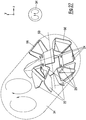
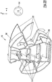
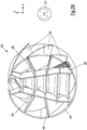
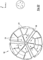
- FIGS. 1 to 32 show different exemplary embodiments of a mixer 10 according to the invention for mixing an exhaust gas stream 12 with a fluid 16 injected into an exhaust gas line 14.
- the mixer 10 in each case comprises both means for generating a swirl and means for radial displacement in the exhaust gas flow axially flowing through the mixer 10, offset by the fluid 16.
- the swirl generating means and the Radial displacement means are each arranged and designed in such a way that at least two separate swirl areas 18 and at least one radial displacement area 20 arranged between two separate swirl areas result over the cross section of the mixer 10 that is perpendicular to the axial exhaust gas flow 12.
- the tangentially acting swirl generating means can include a plurality of swirl elements 22 and the radial displacement means a plurality of radial displacement elements 24. At least some of the swirl elements 22 and / or at least some of the radial displacement elements 24 can each be attached to a carrier element 26 (cf. Figures 13 and 15 ), in particular carrier plate, be supported or formed.
- the swirl regions 18 are at least partially separated from one another by separating elements 27, in particular separating plates.
- the separating elements 27 can also be formed at least partially by carrier elements 26.
- At least some of the separating elements 27 can be axially extended beyond the swirl elements 22 and radial displacement elements 24, in particular to maintain the swirl structure produced.
- the swirl generating means are arranged and designed in such a way that a tangential deflection of the exhaust gas flow 12 mixed with the fluid is generated radially on the outside in a respective swirl region 18.
- a respective radial displacement region 20 can be arranged between adjacent swirl regions 18 over the cross section of the mixer 10 that is perpendicular to the axial exhaust gas flow 12.
- the radial displacement means can be arranged and designed, for example, in such a way that at least two separate radial displacement regions 20 result over the cross section of the mixer 10 that is perpendicular to the axial exhaust gas flow 12.
- the swirl regions 18, which are separated from one another, and / or the various radial displacement regions 20 can each be viewed with mirror symmetry over the cross section of the mixer 10 that is perpendicular to the axial exhaust gas flow 12 (cf., for example, FIG Figs. 1 to 3 , 6th , 11, 12 and 17th ), point-symmetrical (see e.g. the Figures 20, 21 and 25th ) or be arranged without symmetry (see. For example Fig. 23 ).
- a radial displacement area 20 generating a radial displacement in one direction is provided between two swirl areas 18 which are separate from one another and generate swirl in the opposite direction.
- the swirl generating means and the radial displacement means of the mixer 10 are arranged and designed in such a way that four separate swirl regions 18 result, with swirl regions 18 diagonally opposite one another in one direction and through a pair of swirl regions 18 that are diagonally opposite to one another when viewed over the cross section of the mixer 10 that is perpendicular to the axial exhaust gas flow 12
- the mixer 10 shown here again produces four separate swirl regions 18, with swirl regions 18 diagonally opposite one another when viewed over the cross section of the mixer 10 perpendicular to the axial exhaust gas flow 12, swirl in one direction and another pair of swirl regions 18 over the axial exhaust gas flow 12 vertical cross section of the mixer 10 viewed diagonally opposite swirl regions 18 swirl is generated in the opposite direction.
- a first pair of radial displacement regions 20 following one another in a first radial direction viewed across the cross section of the mixer 10 perpendicular to the axial exhaust gas flow and a further pair of radial displacement regions 20 perpendicular to the first radial direction in a cross section of the mixer 10 perpendicular to the axial exhaust gas flow 10 further radial direction successive radial displacement areas 20 are provided.
- a radial displacement in the opposite direction is generated in the two radial displacement areas 20 of a respective pair of radial displacement areas 20 that follow one another in a respective radial direction.
- a respective radial displacement area 20 of the two pairs of radial displacement areas 20 is arranged between two swirl areas 18 which generate swirl in the opposite direction.
- the mixer 10 is shown in the orientation it assumes in the installed state.
- the radial displacement area 20 shown above with a built-in mixer 10 a displacement radially upwards
- the radial displacement area 20 shown below with a built-in mixer 10 a displacement radially downwards
- the upper half and the lower half of the mixer 10 to the right and left of the respective Radial displacement area 20 swirl is generated in the opposite direction.
- the swirl elements 22 can each comprise a base body 28 with at least one curved swirl generating section 30 serving to generate swirl (cf. Fig. 4 ).
- FIG 5A shows, in an isometric view in the direction of flow, a particularly simple embodiment of a mixer 10 not according to the invention
- Figure 5B is this mixer 10 according to Figure 5A shown again in an isometric view against the direction of flow.
- This embodiment of the mixer 10, which is not according to the invention, has sufficient stability, which makes it possible to dispense with the support plates 26 used for component stabilization.
- Fig. 6 shows an exemplary mixer 10, which is acted upon by a fluid spray cone 32.
- a fluid spray cone 32 analogous to the mixer according to Fig. 1 Again, two swirl regions 18 generating swirl in the opposite direction and a radial displacement area 20 arranged between them and generating a radial displacement in one direction are provided.
- the fluid spray cone 32 comprises all three regions 18, 20.
- Fig. 7 shows in a schematic representation exemplary flow conditions and drop ratios in a mixing tube 34 following, for example, a mixer 10 according to FIG Fig. 6 .
- the areas marked in bold show the distributed fluid in the wake of the mixer. The distribution occurs primarily at temperatures which, due to the Leiden frost effect, allow the drops to pass through the mixer instead of evaporating them in the mixing area.
- At least two adjacent swirl regions 18 can be separated from one another by two carrier elements 26, between which a radial displacement region 20 is formed.
- the carrier elements 26 serve to stiffen the mixer and do not contribute to mixing or to droplet formation.
- Fig. 8 an exemplary alternative embodiment in which the two separating elements 27 are arranged at a corresponding angle relative to one another in order to delimit a radial displacement region 20 lying therebetween and continuously widening radially downwards.
- the mixer is again subdivided into two swirl areas 18 and a radial displacement area 20, the radial displacement area 20 being narrower at the top and wider at the bottom, so that a radial displacement area 20 that is at least essentially triangular in cross section results and the best possible ratio of the fluid phase occurring in the radial displacement area and tangential swirl generation area.
- any other subdivision of these areas is also possible.
- FIG. 8 A reinforcement of the proportions of the fluid spray division 36 in the installed state of the mixer 10, viewed downwards, is achieved, as a result of which, in particular, a correspondingly improved fluid droplet distribution results.
- This reinforced fluid spray distribution 36 with downwardly increased fluid proportions is shown in FIG Fig. 8 indicated schematically by arrows and ensures better fluid distribution shortly after the mixer 10.
- Figures 9 and 10 show in schematic cross-sectional and schematic longitudinal section an exemplary radial displacement area 20 with two-stage radial displacement elements 24 generating radial displacement sections 42, between which an intermediate section is arranged without radial displacement.
- the mixer 10 is designed in two parts, it being divisible or divided along a horizontal central plane X, in that, as indicated by dashed lines, continuous carrier elements or carrier plates 26 have been dispensed with or are interrupted.
- the relevant subdivision is matched to the provided swirl areas 18 and radial displacement areas 20. It is not necessary to weld the mixer inside.
- the mixer 10 can be provided without a jacket or with a jacket 44.
- Fig. 12 shows an exemplary embodiment of a mixer 10 according to the invention, in which the jacket 44 of the mixer 10 is oval in cross section. In principle, however, the jacket 44 of the mixer 10 can also be circular or the like.
- the mixer 10 is provided with a jacket 44, this can also be produced at least partially by swirl elements 22.
- embodiments of the mixer 10 are also conceivable in which at least one pair of opposing swirl elements 22 with a radial displacement element 24 arranged between them forms a one-piece or one-piece and elongated component 46.
- a respective one-piece or elongated component 46 comprising a pair of swirl elements 22 and a radial displacement element 24 arranged between them can be supported at least partially on two adjacent carrier elements or carrier plates 26, by means of which the swirl regions 18 and the radial displacement region 20 in question from each other at the same time be separated.
- a respective one-piece component 46 comprising a pair of swirl elements 22 and a one-piece component 46 arranged between them can be at least partially supported on the two adjacent carrier elements or carrier plates 26 by engaging in sections in slots 48 provided in the carrier elements or carrier plates 26 .
- the swirl elements 22 can each comprise a section that is bent in particular in the manner of a wing.
- the components 46 can, for example, only be connected externally and, for example, welded to the mixing tube. On the inside, welding can either be dispensed with entirely, or fixation can be carried out using relatively few welding points.
- support elements can be dispensed with, as is shown in FIG. 33.
- the mixer 10 comprises a radial displacement region 20 which is laterally offset with respect to a center plane 50 extending in the axial direction and which contributes to increasing the mixing in the case of an asymmetrical flow into the gas phase or the asymmetrical application of the fluid phase.
- Mixing and distribution can be increased further, for example, that, as in Fig. 17 shown, the mixer 10 is provided with swirl regions 18 having different swirl angles.
- the mixer 10 is provided with swirl regions 18 having different swirl angles.
- two separate areas are generated, one of which on one side of a radial displacement area 20 has two swirl areas 18 each with a swirl angle of, for example, 35 ° and one on the opposite side of the radial displacement area 20 has two swirl areas 18 each having a twist angle of 45 °, for example.
- the generation of an asymmetrical fluid spray cone or an asymmetrical flow is again conceivable.
- this design prevents the dominance of a respective twist over another twist which could otherwise be resolved. These measures may also be necessary in asymmetrical conditions.
- Fig. 18 shows a schematic cross-sectional illustration of a swirl element 22 set at a certain swirl angle ⁇ to the axial exhaust gas flow 12.
- Fig. 19 shows a schematic longitudinal sectional view of an exemplary embodiment of a mixer 10 according to the invention arranged within the exhaust line 14, the mixer 10 having a smaller cross section than the exhaust line 14 to form a bypass 52 surrounding it in an annular manner.
- the Figures 20 and 21 show in schematic cross-sectional representations two exemplary embodiments of the mixer 10 according to the invention with both point-symmetrically arranged swirl regions 18 and point-symmetrically arranged radial displacement regions 20 Fig. 20 two mutually parallel radial displacement regions 20 generating the radial displacement in the opposite direction are provided, while in the embodiment according to FIG Fig. 21
- three radial displacement regions 20 arranged in a star shape are provided, in each of which the exhaust gas is displaced radially outward.
- swirl is generated in the same direction.
- the separating elements or separating plates 27 can be used to maintain the generated Swirl structure be axially extended beyond the swirl elements 22 and radial displacement elements 24.
- the swirl structure produced in the exhaust pipe is maintained for a longer period of time. Due to the elongated separating elements 27 indicated by dotted lines, the smaller micro-twist regions, viewed in the flow direction of the exhaust gas, only combine later to form a macro-twist.
- the mixer 10 comprises at least one downstream separating element 27 ', which is separated from the multiple swirl area and the at least one radial displacement area.
- the effective separating area is extended to a length l 3 , which goes well beyond the last-mentioned separating area length l 2.
- the starting point l 4 from which the microstructure of the multiple twist such as one with the mixer 10 according to FIG Fig. 21
- the triple twist generated begins to unite or disintegrate and, for example, to transform into a mono twist, correspondingly further back than the relevant starting point l 5 resulting from the separation area length l 2 .
- the mixer 10 can also be designed, for example, in such a way that both the generated swirl regions 18 and the generated radial displacement regions 20 are each arranged without symmetry. As indicated by dotted lines, at least one extended separating element or
- Separating plate 27 can be provided in order to maintain the micro-vortex longer or to push out the starting point from which the microstructure of the multiple twist begins to unite or disintegrate and, for example, to transform into a mono-twist.
- Fig. 24 shows a schematic representation of the mixer according to FIG Fig. 23 in a mixing pipe 34 or in the exhaust line following the mixer 10 resulting swirl.
- Fig. 25 shows an exemplary embodiment of a point-symmetrical mixer 10 with elongated separating elements or separating plates 27 again indicated here in dotted lines, in which the adjacent swirl regions 18 are separated from one another by only one separating element or separating plate 27.
- the separating elements 27 are arranged in a star shape to form three swirl areas 18, in each of which swirl is generated counterclockwise, with a radial displacement in the opposite direction on both sides of a respective separating element 27.
- Fig. 26 is that with the mixer 10 according to Fig. 25 in a mixing tube 34 following the mixer 10 or in the exhaust pipe resulting swirl shown schematically.
- Fig. 27 shows an example of a casing-free embodiment of a mixer 10 according to the invention in a mirror-symmetrical, split design for generating two swirl regions generating swirl in opposite directions.
- the dividing plane 60 and the double swirl 54 resulting in the adjoining exhaust gas or mixing pipe 34 can also be seen.
- the relevant support elements or support plates 26 as well as connection points 56 for connecting the mixer 10 to the exhaust pipe 34.
- the mixer 10 is made in two parts, in that it can be assembled from two sheet metal parts that are bent or folded to form the swirl elements 22, radial displacement elements 24 and support elements 26 or is composed. Accordingly, this is a mixer 10 of relatively simple construction.
- the orientation of the mixer 10 in the Fig. 27 corresponds as well as that in the following Figures 28 to 32 shown mixer 10 each their orientation in the installed state, so that, for example, in the representation according to Fig. 27
- the upper area and the lower area correspond to the upper and lower areas of the built-in mixer 10, respectively.
- a further exemplary embodiment of the mixer 10 according to the invention without a casing is shown in a perspective view in a mirror-symmetrical design and with two swirl regions generating swirl in opposite directions.
- the relevant swirl elements 22, radial displacement elements 24, carrier elements or carrier plates 26 as well as connection points 56 for connecting the mixer 10 to the mixing or exhaust pipe 34 can also be seen again.
- the resulting double twist 54 is also shown again in the present case.
- Fig. 29 shows a perspective view of a further exemplary embodiment of the mixer 10 according to the invention in a mirror-symmetrical design with a jacket 44, two swirl areas generating swirl in opposite directions and pairs of swirl elements 22 lying opposite one another, each of which with a radial displacement element 24 arranged between them is a one-piece or elongated component 46 form. Also in the present case is In addition to the mixer 10, the resulting counter-rotating double swirl 54 is shown again.
- the mixer 10 is again mirror-symmetrical and with a jacket 44 and four swirl regions separated from one another for generating symmetrical vortices 58, as they are shown schematically next to the mixer 10.
- the relevant swirl elements 22, radial displacement elements 24 and carrier elements or carrier plates 26 can also be seen again.
- the mixer 10 is designed without a jacket, divided or divisible and with three swirl areas separated from one another.
- the resulting swirl is again shown schematically next to the mixer 10.
- the connection points 56 for connecting the mixer 10 to the exhaust gas or mixing pipe 14 or 34 can also be seen again.
- Fig. 32 shows a perspective view of an exemplary embodiment of the mixer 10 according to the invention in a point-symmetrical design with three swirl areas separated from one another, wherein the number of carrier elements or carrier plates 26 can in particular be equal to the number of swirl elements 22.
- the relevant radial displacement elements 24 and carrier elements or carrier plates 26 can also be seen again.
Landscapes
- Chemical & Material Sciences (AREA)
- Chemical Kinetics & Catalysis (AREA)
- Engineering & Computer Science (AREA)
- Dispersion Chemistry (AREA)
- Health & Medical Sciences (AREA)
- Toxicology (AREA)
- Combustion & Propulsion (AREA)
- Mechanical Engineering (AREA)
- General Engineering & Computer Science (AREA)
- Exhaust Gas After Treatment (AREA)
Claims (15)
- Mélangeur (10) pour mélanger un flux de gaz d'échappement (12) avec un fluide (16) injecté dans une conduite d'échappement (14), comportant des moyens de génération d'un tourbillon provoquant un écoulement rotatif et des moyens de déplacement radial dans le flux de gaz d'échappement (12) muni du fluide (16) et traversant axialement le mélangeur (10), les moyens de génération de tourbillon et les moyens de déplacement radial étant disposés et réalisés de telle sorte que, vu sur la section transversale du mélangeur (10) perpendiculairement au flux de gaz d'échappement axial (12), il se forme au moins deux zones de tourbillonnement (18) séparées l'une de l'autre, constituées par des éléments de tourbillonnement (22) en forme d'aubes agissant tangentiellement, et séparées l'une de l'autre au moins partiellement par des éléments de séparation (27), ainsi qu'au moins une zone de déplacement radial (20) respective disposée entre deux zones de tourbillonnement (18) séparées l'une de l'autre.
- Mélangeur selon la revendication 1,
caractérisé en ce queles moyens de génération de tourbillon comprennent une pluralité d'éléments de tourbillonnement (22) en forme d'aubes, agissant surtout tangentiellement, et/oules moyens de déplacement radial comprennent une pluralité d'éléments de déplacement radial (24), etde préférence, les éléments de tourbillonnement (22) et/ou une partie au moins des éléments de déplacement radial (24) sont chacun supportés ou réalisés sur une pièce de support (26), en particulier sur une tôle de support. - Mélangeur selon l'une au moins des revendications précédentes,
caractérisé en ce que
les éléments de séparation (27) sont réalisés au moins partiellement par les pièces de support (26). - Mélangeur selon la revendication 3,
caractérisé en ce que
une partie au moins des éléments de séparation (27) est prolongée axialement au-delà des éléments de tourbillonnement (22) et des éléments de déplacement radial (24), en particulier pour maintenir la structure de tourbillonnement générée. - Mélangeur selon l'une au moins des revendications précédentes,
caractérisé en ce queune zone de déplacement radial (20) respective est disposée entre des zones de tourbillonnement (18) voisines, vues sur la section transversale du mélangeur (10) perpendiculairement au flux de gaz d'échappement axial (12), et/ou en ce queles moyens de déplacement radial sont disposés et réalisés de telle sorte qu'il se forme au moins deux zones de déplacement radial (20) distinctes, vues sur la section transversale du mélangeur (10) perpendiculairement au flux de gaz d'échappement axial (12), et/ou en ce que les zones de tourbillonnement (18) séparées l'une de l'autre et/ou les zones de déplacement radial (20) distinctes sont chacune disposées à symétrie axiale ou à symétrie ponctuelle ou sans symétrie, vues sur la section transversale du mélangeur (10) perpendiculairement au flux de gaz d'échappement axial (12). - Mélangeur selon l'une au moins des revendications précédentes, caractérisé en ce queil est prévu au moins deux zones de tourbillonnement (18) séparées l'une de l'autre, dans lesquelles des tourbillons sont générés dans des directions opposées, etde préférence, il est prévu au moins une zone de déplacement radial (20) entre les deux zones de tourbillonnement (18) séparées l'une de l'autre et générant des tourbillons dans des directions opposées.
- Mélangeur selon l'une au moins des revendications précédentes,
caractérisé en ce queil est prévu au moins deux zones de tourbillonnement (18) séparées l'une de l'autre, générant des tourbillons dans des directions opposées, entre lesquelles est disposée une zone de déplacement radial (20) générant un déplacement radial dans une direction, et/ouil est prévu au moins deux zones de tourbillonnement (18) séparées l'une de l'autre, générant des tourbillons dans des directions opposées, entre lesquelles sont disposées deux zones de déplacement radial (20) générant un déplacement radial dans des directions opposées, et/ou il est prévu quatre zones de tourbillonnement (18) distinctes, un tourbillon étant généré dans une direction par une paire de zones de tourbillonnement (18) diagonalement opposées l'une à l'autre, vues sur la section transversale du mélangeur (10) perpendiculairement au flux de gaz d'échappement axial (12), et un tourbillon étant généré dans la direction opposée par une autre paire de zones de tourbillonnement (18) diagonalement opposées l'une à l'autre, vues sur la section transversale du mélangeur (10) perpendiculairement au flux de gaz d'échappement axial (12), etde préférence, il est prévu deux zones de déplacement radial (20) qui se suivent dans la direction radiale, vues sur la section transversale du mélangeur (10) perpendiculairement au flux de gaz d'échappement axial (12), et qui sont disposées chacune entre deux zones de tourbillonnement (18) générant des tourbillons dans des directions opposées, etde préférence encore, un déplacement radial dans des directions opposées est généré dans les deux zones de déplacement radial (20) qui se suivent dans la direction radiale. - Mélangeur selon la revendication 7,
caractérisé en ce queil est prévu une première paire de zones de déplacement radial (20) qui se suivent dans une première direction radiale, vue sur la section transversale du mélangeur (10) perpendiculairement au flux de gaz d'échappement axial, etil est prévu une autre paire de zones de déplacement radial (20) qui se suivent dans une autre direction radiale perpendiculaire à la première direction radiale, vue sur la section transversale du mélangeur (10) perpendiculairement au flux de gaz d'échappement axial (12), etde préférence, un déplacement radial dans les directions opposées est généré dans les deux zones de déplacement radial (20) d'une paire respective de zones de déplacement radial (20) qui se suivent dans une direction radiale respective. - Mélangeur selon la revendication 8,
caractérisé en ce que
une zone de déplacement radial (20) respective des deux paires de zones de déplacement radial (20) est disposée entre deux zones de tourbillonnement (18) générant un tourbillon dans des directions opposées. - Mélangeur selon l'une au moins des revendications précédentes,
caractérisé en ce que
une partie au moins des éléments de tourbillonnement (22) est formée par une tôle de tourbillonnement ou tôle tangentielle, et/ou une partie au moins des éléments de déplacement radial (24) est formée par une tôle radiale. - Mélangeur selon l'une au moins des revendications précédentes,
caractérisé en ce queles éléments de déplacement radial (24) comprennent chacun un corps de base (38) ayant au moins une portion de déplacement radial (42) servant au déplacement radial, etde préférence, le corps de base (38) d'une partie au moins des éléments de déplacement radial (24) est pourvu d'une seule portion de déplacement radial (42) générant en continu un déplacement radial, vue dans la direction du flux de gaz d'échappement axial (12), et/oude préférence, le corps de base (38) d'une partie au moins des éléments de déplacement radial (24) est pourvu d'au moins deux portions de déplacement radial (42) générant en continu un déplacement radial, vues dans la direction du flux de gaz d'échappement axial (12), etune portion intermédiaire respective sans déplacement radial est prévue entre une portion de déplacement radial (42) respective précédente et une portion de déplacement radial (42) respective suivante. - Mélangeur selon l'une au moins des revendications précédentes,
caractérisé en ce quele mélangeur (10) est dépourvu d'enveloppe, ou en ce que le mélangeur (10) est pourvu d'une enveloppe (44), l'enveloppe (44) étant de préférence formée au moins partiellement par des éléments de tourbillonnement (22), et/oude préférence, l'enveloppe (44) présente une section transversale au moins sensiblement circulaire ou ovale. - Mélangeur selon l'une au moins des revendications précédentes,
caractérisé en ce queil est prévu au moins une paire d'éléments de tourbillonnement (22) opposés l'un à l'autre, ladite paire formant un composant monobloc (46) avec au moins un élément de déplacement radial (24) interposé, etde préférence, un composant monobloc (46) respectif comprenant une paire d'éléments de tourbillonnement (22) et au moins un élément de déplacement radial (24) interposé est supporté au moins partiellement sur deux pièces de support ou tôles de support (26) voisines, séparant les zones de tourbillonnement (18) correspondantes et ladite au moins une zone de déplacement radial (20) correspondante, etde préférence encore, un composant monobloc (46) respectif comprenant une paire d'éléments de tourbillonnement (22) et au moins un élément de déplacement radial (24) interposé est au moins partiellement supporté sur les deux pièces de support ou tôles de support (26) voisines en s'engageant localement dans des fentes (48) prévues dans les pièces de support ou tôles de support (26). - Mélangeur selon l'une au moins des revendications précédentes,
caractérisé en ce queles moyens de déplacement radial sont disposés et réalisés de telle sorte que, vu sur la section transversale du mélangeur (10) perpendiculairement au flux de gaz d'échappement axial (12), il se forme au moins une zone de déplacement radial (20) décalée latéralement par rapport à un plan médian (50) s'étendant dans la direction axiale, et/ou en ce que les éléments de tourbillonnement (22) sont disposés et réalisés de telle sorte qu'il se forme des zones de tourbillonnement (18) ayant différents angles de tourbillonnement (a), et/ou en ce que au moins deux zones de tourbillonnement (18) voisines sont séparées l'une de l'autre par deux éléments de séparation (27), entre lesquels est formée une zone de déplacement radial (20), etde préférence, les deux éléments de séparation (27) sont alignés parallèlement l'un à l'autre pour délimiter une zone de déplacement radial (20) interposée de largeur constante radialement en continu, oude préférence, les deux éléments de séparation (27) sont disposés selon un angle correspondant l'un par rapport à l'autre pour délimiter une zone de déplacement radial (20) interposée dont la largeur augmente en continu dans la direction radiale. - Mélangeur selon l'une au moins des revendications précédentes, caractérisé par l'une au moins des caractéristiques suivantes :- en particulier dans le cas d'une disposition à symétrie ponctuelle des éléments de tourbillonnement (22) et/ou des éléments de déplacement radial (24), le nombre de pièces de support ou tôles de support (26) est égal au nombre de zones de tourbillonnement (18) générées,- le mélangeur (10) est réalisé en deux parties en pouvant être assemblé ou en étant assemblé à partir de deux pièces de tôle qui sont pliées ou courbées en correspondance pour réaliser les éléments de tourbillonnement (22), les éléments de déplacement radial (24) et les pièces de support (26),- le mélangeur (10) comprend des moyens de distribution de gouttelettes de fluide et/ou des moyens d'amplification des proportions de la distribution du jet de fluide en particulier vers le bas, vu dans l'état assemblé du mélangeur,- pour maintenir la structure de tourbillonnement générée, le mélangeur (10) comprend au moins un élément de séparation aval (27') séparé de la zone de tourbillonnement multiple et de ladite au moins une zone de déplacement radial.
Applications Claiming Priority (1)
| Application Number | Priority Date | Filing Date | Title |
|---|---|---|---|
| DE102019103780.8A DE102019103780B4 (de) | 2019-02-14 | 2019-02-14 | Mischer |
Publications (2)
| Publication Number | Publication Date |
|---|---|
| EP3696383A1 EP3696383A1 (fr) | 2020-08-19 |
| EP3696383B1 true EP3696383B1 (fr) | 2021-10-20 |
Family
ID=69726413
Family Applications (1)
| Application Number | Title | Priority Date | Filing Date |
|---|---|---|---|
| EP20156882.1A Active EP3696383B1 (fr) | 2019-02-14 | 2020-02-12 | Mélangeur |
Country Status (5)
| Country | Link |
|---|---|
| US (1) | US11781462B2 (fr) |
| EP (1) | EP3696383B1 (fr) |
| CN (1) | CN111558306A (fr) |
| DE (1) | DE102019103780B4 (fr) |
| ES (1) | ES2897513T3 (fr) |
Families Citing this family (2)
| Publication number | Priority date | Publication date | Assignee | Title |
|---|---|---|---|---|
| DE102019127882A1 (de) * | 2019-10-16 | 2021-04-22 | Eberspächer Exhaust Technology GmbH | Mischeranordnung |
| US10941692B1 (en) * | 2019-11-01 | 2021-03-09 | Tenneco Automotive Operating Company Inc. | Mixer assembly for exhaust aftertreatment system |
Family Cites Families (13)
| Publication number | Priority date | Publication date | Assignee | Title |
|---|---|---|---|---|
| US1113041A (en) * | 1914-05-12 | 1914-10-06 | John J Murphy | Gaseous-fuel mixer |
| DE102007009890B4 (de) * | 2007-02-28 | 2025-05-28 | Emcon Technologies Germany (Augsburg) Gmbh | Statisches Mischelement sowie Verfahren zur Herstellung eines statischen Mischelements |
| US8939638B2 (en) * | 2008-04-21 | 2015-01-27 | Tenneco Automotive Operating Company Inc. | Method for mixing an exhaust gas flow |
| DE112012003429A5 (de) * | 2011-12-14 | 2014-04-30 | Friedrich Boysen Gmbh & Co. Kg | Mischereinrichtung |
| DE102012218565B4 (de) * | 2012-10-11 | 2015-07-16 | Eberspächer Exhaust Technology GmbH & Co. KG | Abgasanlage mit Leitungselement |
| US20150040547A1 (en) * | 2013-08-08 | 2015-02-12 | Tenneco Automotive Operating Company Inc. | Mirrored Two-Stage Mixer |
| EP2865861B2 (fr) | 2013-10-22 | 2019-05-15 | Eberspächer Exhaust Technology GmbH & Co. KG | Système de catalyseur avec section d'injection |
| DE112014005413B4 (de) * | 2013-11-26 | 2019-08-29 | Tenneco Automotive Operating Company Inc. | Abgasstrommischer |
| CN105980679B (zh) * | 2014-02-07 | 2019-04-23 | 佛吉亚排放控制技术美国有限公司 | 用于车辆排气系统的混合器组件 |
| AT516102B1 (de) * | 2014-08-14 | 2017-09-15 | MAN Truck & Bus Österreich AG | Abgasreinigungsvorrichtung für ein Fahrzeug, insbesondere für ein Nutzfahrzeug |
| DE102014222296A1 (de) * | 2014-10-31 | 2016-05-04 | Eberspächer Exhaust Technology GmbH & Co. KG | Abgasbehandlungseinrichtung |
| DE102016102020A1 (de) * | 2015-04-23 | 2016-10-27 | Friedrich Boysen Gmbh & Co. Kg | Mischereinrichtung |
| CN205055840U (zh) * | 2015-09-02 | 2016-03-02 | 中冶华天南京工程技术有限公司 | 气体旋流器以及旋流混合器 |
-
2019
- 2019-02-14 DE DE102019103780.8A patent/DE102019103780B4/de active Active
-
2020
- 2020-02-12 EP EP20156882.1A patent/EP3696383B1/fr active Active
- 2020-02-12 CN CN202010087958.4A patent/CN111558306A/zh active Pending
- 2020-02-12 ES ES20156882T patent/ES2897513T3/es active Active
- 2020-02-14 US US16/791,041 patent/US11781462B2/en active Active
Also Published As
| Publication number | Publication date |
|---|---|
| US11781462B2 (en) | 2023-10-10 |
| ES2897513T3 (es) | 2022-03-01 |
| US20200263590A1 (en) | 2020-08-20 |
| DE102019103780A1 (de) | 2020-08-20 |
| DE102019103780B4 (de) | 2024-01-25 |
| CN111558306A (zh) | 2020-08-21 |
| EP3696383A1 (fr) | 2020-08-19 |
Similar Documents
| Publication | Publication Date | Title |
|---|---|---|
| EP2865861B2 (fr) | Système de catalyseur avec section d'injection | |
| DE102010009043B4 (de) | Statischer Mischer für eine Abgasanlage einer Brennkraftmaschine | |
| DE102006055036B4 (de) | Mischelement sowie Abgasanlage für eine Verbrennungskraftmaschine | |
| EP0526393B1 (fr) | dispositif d'immixtion | |
| DE102011111765B4 (de) | Mischereinrichtung | |
| EP0546989B1 (fr) | Elément de mélange statique avec surfaces de guidage | |
| DE102016104361A1 (de) | Mischer | |
| DE102008029110A1 (de) | Misch- und/oder Verdampfungseinrichtung | |
| EP3757364A1 (fr) | Mélangeur pour un système scr de traitement des gaz d'échappement | |
| EP3696383B1 (fr) | Mélangeur | |
| DE102017105093A1 (de) | Mischereinrichtung | |
| EP3726017B1 (fr) | Mélangeur | |
| DE112017002859T5 (de) | Doppelmischer für Abgasnachbehandlungssysteme | |
| DE102012014528A1 (de) | Mehrstufiger Plattenmischer | |
| DE102020101226A1 (de) | Vorrichtung zum Einbringen und Verteilen einer Flüssigkeit in einen Gasstrom | |
| DE102013202790A1 (de) | Wärmeübertrager | |
| DE102016102020A1 (de) | Mischereinrichtung | |
| DE102011120221A1 (de) | Mischer für eine Abgasanlage und Abgasanlage | |
| DE102019104772A1 (de) | Abgasanlage | |
| WO2013087850A1 (fr) | Dispositif mélangeur | |
| WO2008074414A1 (fr) | Tuyau d'échappement pour un système d'échappement d'un moteur à combustion interne | |
| DE102016014966A1 (de) | Abgasnachbehandlungseinrichtung für einen Kraftwagen | |
| DE102013210804A1 (de) | Mischereinrichtung | |
| WO2013087852A2 (fr) | Dispositif mélangeur | |
| AT521002A1 (de) | Mischeinrichtung |
Legal Events
| Date | Code | Title | Description |
|---|---|---|---|
| PUAI | Public reference made under article 153(3) epc to a published international application that has entered the european phase |
Free format text: ORIGINAL CODE: 0009012 |
|
| STAA | Information on the status of an ep patent application or granted ep patent |
Free format text: STATUS: THE APPLICATION HAS BEEN PUBLISHED |
|
| AK | Designated contracting states |
Kind code of ref document: A1 Designated state(s): AL AT BE BG CH CY CZ DE DK EE ES FI FR GB GR HR HU IE IS IT LI LT LU LV MC MK MT NL NO PL PT RO RS SE SI SK SM TR |
|
| AX | Request for extension of the european patent |
Extension state: BA ME |
|
| STAA | Information on the status of an ep patent application or granted ep patent |
Free format text: STATUS: REQUEST FOR EXAMINATION WAS MADE |
|
| 17P | Request for examination filed |
Effective date: 20210215 |
|
| RBV | Designated contracting states (corrected) |
Designated state(s): AL AT BE BG CH CY CZ DE DK EE ES FI FR GB GR HR HU IE IS IT LI LT LU LV MC MK MT NL NO PL PT RO RS SE SI SK SM TR |
|
| GRAP | Despatch of communication of intention to grant a patent |
Free format text: ORIGINAL CODE: EPIDOSNIGR1 |
|
| STAA | Information on the status of an ep patent application or granted ep patent |
Free format text: STATUS: GRANT OF PATENT IS INTENDED |
|
| INTG | Intention to grant announced |
Effective date: 20210429 |
|
| GRAS | Grant fee paid |
Free format text: ORIGINAL CODE: EPIDOSNIGR3 |
|
| GRAA | (expected) grant |
Free format text: ORIGINAL CODE: 0009210 |
|
| STAA | Information on the status of an ep patent application or granted ep patent |
Free format text: STATUS: THE PATENT HAS BEEN GRANTED |
|
| AK | Designated contracting states |
Kind code of ref document: B1 Designated state(s): AL AT BE BG CH CY CZ DE DK EE ES FI FR GB GR HR HU IE IS IT LI LT LU LV MC MK MT NL NO PL PT RO RS SE SI SK SM TR |
|
| REG | Reference to a national code |
Ref country code: GB Ref legal event code: FG4D Free format text: NOT ENGLISH |
|
| REG | Reference to a national code |
Ref country code: CH Ref legal event code: EP |
|
| REG | Reference to a national code |
Ref country code: DE Ref legal event code: R096 Ref document number: 502020000278 Country of ref document: DE |
|
| REG | Reference to a national code |
Ref country code: IE Ref legal event code: FG4D Free format text: LANGUAGE OF EP DOCUMENT: GERMAN |
|
| REG | Reference to a national code |
Ref country code: AT Ref legal event code: REF Ref document number: 1440131 Country of ref document: AT Kind code of ref document: T Effective date: 20211115 |
|
| REG | Reference to a national code |
Ref country code: LT Ref legal event code: MG9D |
|
| REG | Reference to a national code |
Ref country code: NL Ref legal event code: MP Effective date: 20211020 |
|
| REG | Reference to a national code |
Ref country code: ES Ref legal event code: FG2A Ref document number: 2897513 Country of ref document: ES Kind code of ref document: T3 Effective date: 20220301 |
|
| PG25 | Lapsed in a contracting state [announced via postgrant information from national office to epo] |
Ref country code: RS Free format text: LAPSE BECAUSE OF FAILURE TO SUBMIT A TRANSLATION OF THE DESCRIPTION OR TO PAY THE FEE WITHIN THE PRESCRIBED TIME-LIMIT Effective date: 20211020 Ref country code: LT Free format text: LAPSE BECAUSE OF FAILURE TO SUBMIT A TRANSLATION OF THE DESCRIPTION OR TO PAY THE FEE WITHIN THE PRESCRIBED TIME-LIMIT Effective date: 20211020 Ref country code: FI Free format text: LAPSE BECAUSE OF FAILURE TO SUBMIT A TRANSLATION OF THE DESCRIPTION OR TO PAY THE FEE WITHIN THE PRESCRIBED TIME-LIMIT Effective date: 20211020 Ref country code: BG Free format text: LAPSE BECAUSE OF FAILURE TO SUBMIT A TRANSLATION OF THE DESCRIPTION OR TO PAY THE FEE WITHIN THE PRESCRIBED TIME-LIMIT Effective date: 20220120 |
|
| PG25 | Lapsed in a contracting state [announced via postgrant information from national office to epo] |
Ref country code: IS Free format text: LAPSE BECAUSE OF FAILURE TO SUBMIT A TRANSLATION OF THE DESCRIPTION OR TO PAY THE FEE WITHIN THE PRESCRIBED TIME-LIMIT Effective date: 20220220 Ref country code: SE Free format text: LAPSE BECAUSE OF FAILURE TO SUBMIT A TRANSLATION OF THE DESCRIPTION OR TO PAY THE FEE WITHIN THE PRESCRIBED TIME-LIMIT Effective date: 20211020 Ref country code: PT Free format text: LAPSE BECAUSE OF FAILURE TO SUBMIT A TRANSLATION OF THE DESCRIPTION OR TO PAY THE FEE WITHIN THE PRESCRIBED TIME-LIMIT Effective date: 20220221 Ref country code: PL Free format text: LAPSE BECAUSE OF FAILURE TO SUBMIT A TRANSLATION OF THE DESCRIPTION OR TO PAY THE FEE WITHIN THE PRESCRIBED TIME-LIMIT Effective date: 20211020 Ref country code: NO Free format text: LAPSE BECAUSE OF FAILURE TO SUBMIT A TRANSLATION OF THE DESCRIPTION OR TO PAY THE FEE WITHIN THE PRESCRIBED TIME-LIMIT Effective date: 20220120 Ref country code: NL Free format text: LAPSE BECAUSE OF FAILURE TO SUBMIT A TRANSLATION OF THE DESCRIPTION OR TO PAY THE FEE WITHIN THE PRESCRIBED TIME-LIMIT Effective date: 20211020 Ref country code: LV Free format text: LAPSE BECAUSE OF FAILURE TO SUBMIT A TRANSLATION OF THE DESCRIPTION OR TO PAY THE FEE WITHIN THE PRESCRIBED TIME-LIMIT Effective date: 20211020 Ref country code: HR Free format text: LAPSE BECAUSE OF FAILURE TO SUBMIT A TRANSLATION OF THE DESCRIPTION OR TO PAY THE FEE WITHIN THE PRESCRIBED TIME-LIMIT Effective date: 20211020 Ref country code: GR Free format text: LAPSE BECAUSE OF FAILURE TO SUBMIT A TRANSLATION OF THE DESCRIPTION OR TO PAY THE FEE WITHIN THE PRESCRIBED TIME-LIMIT Effective date: 20220121 |
|
| REG | Reference to a national code |
Ref country code: DE Ref legal event code: R097 Ref document number: 502020000278 Country of ref document: DE |
|
| PG25 | Lapsed in a contracting state [announced via postgrant information from national office to epo] |
Ref country code: SM Free format text: LAPSE BECAUSE OF FAILURE TO SUBMIT A TRANSLATION OF THE DESCRIPTION OR TO PAY THE FEE WITHIN THE PRESCRIBED TIME-LIMIT Effective date: 20211020 Ref country code: SK Free format text: LAPSE BECAUSE OF FAILURE TO SUBMIT A TRANSLATION OF THE DESCRIPTION OR TO PAY THE FEE WITHIN THE PRESCRIBED TIME-LIMIT Effective date: 20211020 Ref country code: RO Free format text: LAPSE BECAUSE OF FAILURE TO SUBMIT A TRANSLATION OF THE DESCRIPTION OR TO PAY THE FEE WITHIN THE PRESCRIBED TIME-LIMIT Effective date: 20211020 Ref country code: EE Free format text: LAPSE BECAUSE OF FAILURE TO SUBMIT A TRANSLATION OF THE DESCRIPTION OR TO PAY THE FEE WITHIN THE PRESCRIBED TIME-LIMIT Effective date: 20211020 Ref country code: DK Free format text: LAPSE BECAUSE OF FAILURE TO SUBMIT A TRANSLATION OF THE DESCRIPTION OR TO PAY THE FEE WITHIN THE PRESCRIBED TIME-LIMIT Effective date: 20211020 Ref country code: CZ Free format text: LAPSE BECAUSE OF FAILURE TO SUBMIT A TRANSLATION OF THE DESCRIPTION OR TO PAY THE FEE WITHIN THE PRESCRIBED TIME-LIMIT Effective date: 20211020 |
|
| PLBE | No opposition filed within time limit |
Free format text: ORIGINAL CODE: 0009261 |
|
| STAA | Information on the status of an ep patent application or granted ep patent |
Free format text: STATUS: NO OPPOSITION FILED WITHIN TIME LIMIT |
|
| 26N | No opposition filed |
Effective date: 20220721 |
|
| PG25 | Lapsed in a contracting state [announced via postgrant information from national office to epo] |
Ref country code: MC Free format text: LAPSE BECAUSE OF FAILURE TO SUBMIT A TRANSLATION OF THE DESCRIPTION OR TO PAY THE FEE WITHIN THE PRESCRIBED TIME-LIMIT Effective date: 20211020 |
|
| REG | Reference to a national code |
Ref country code: BE Ref legal event code: MM Effective date: 20220228 |
|
| PG25 | Lapsed in a contracting state [announced via postgrant information from national office to epo] |
Ref country code: LU Free format text: LAPSE BECAUSE OF NON-PAYMENT OF DUE FEES Effective date: 20220212 Ref country code: AL Free format text: LAPSE BECAUSE OF FAILURE TO SUBMIT A TRANSLATION OF THE DESCRIPTION OR TO PAY THE FEE WITHIN THE PRESCRIBED TIME-LIMIT Effective date: 20211020 |
|
| PG25 | Lapsed in a contracting state [announced via postgrant information from national office to epo] |
Ref country code: SI Free format text: LAPSE BECAUSE OF FAILURE TO SUBMIT A TRANSLATION OF THE DESCRIPTION OR TO PAY THE FEE WITHIN THE PRESCRIBED TIME-LIMIT Effective date: 20211020 |
|
| PG25 | Lapsed in a contracting state [announced via postgrant information from national office to epo] |
Ref country code: IE Free format text: LAPSE BECAUSE OF NON-PAYMENT OF DUE FEES Effective date: 20220212 |
|
| PG25 | Lapsed in a contracting state [announced via postgrant information from national office to epo] |
Ref country code: BE Free format text: LAPSE BECAUSE OF NON-PAYMENT OF DUE FEES Effective date: 20220228 |
|
| REG | Reference to a national code |
Ref country code: CH Ref legal event code: PL |
|
| PG25 | Lapsed in a contracting state [announced via postgrant information from national office to epo] |
Ref country code: LI Free format text: LAPSE BECAUSE OF NON-PAYMENT OF DUE FEES Effective date: 20230228 Ref country code: CH Free format text: LAPSE BECAUSE OF NON-PAYMENT OF DUE FEES Effective date: 20230228 |
|
| PG25 | Lapsed in a contracting state [announced via postgrant information from national office to epo] |
Ref country code: MK Free format text: LAPSE BECAUSE OF FAILURE TO SUBMIT A TRANSLATION OF THE DESCRIPTION OR TO PAY THE FEE WITHIN THE PRESCRIBED TIME-LIMIT Effective date: 20211020 Ref country code: CY Free format text: LAPSE BECAUSE OF FAILURE TO SUBMIT A TRANSLATION OF THE DESCRIPTION OR TO PAY THE FEE WITHIN THE PRESCRIBED TIME-LIMIT Effective date: 20211020 |
|
| PG25 | Lapsed in a contracting state [announced via postgrant information from national office to epo] |
Ref country code: HU Free format text: LAPSE BECAUSE OF FAILURE TO SUBMIT A TRANSLATION OF THE DESCRIPTION OR TO PAY THE FEE WITHIN THE PRESCRIBED TIME-LIMIT; INVALID AB INITIO Effective date: 20200212 |
|
| PG25 | Lapsed in a contracting state [announced via postgrant information from national office to epo] |
Ref country code: MT Free format text: LAPSE BECAUSE OF FAILURE TO SUBMIT A TRANSLATION OF THE DESCRIPTION OR TO PAY THE FEE WITHIN THE PRESCRIBED TIME-LIMIT Effective date: 20211020 |
|
| PGFP | Annual fee paid to national office [announced via postgrant information from national office to epo] |
Ref country code: AT Payment date: 20250417 Year of fee payment: 5 |
|
| PGFP | Annual fee paid to national office [announced via postgrant information from national office to epo] |
Ref country code: DE Payment date: 20250428 Year of fee payment: 6 |
|
| PGFP | Annual fee paid to national office [announced via postgrant information from national office to epo] |
Ref country code: ES Payment date: 20250331 Year of fee payment: 6 |
|
| PG25 | Lapsed in a contracting state [announced via postgrant information from national office to epo] |
Ref country code: TR Free format text: LAPSE BECAUSE OF FAILURE TO SUBMIT A TRANSLATION OF THE DESCRIPTION OR TO PAY THE FEE WITHIN THE PRESCRIBED TIME-LIMIT Effective date: 20211020 |
|
| PGFP | Annual fee paid to national office [announced via postgrant information from national office to epo] |
Ref country code: GB Payment date: 20260220 Year of fee payment: 7 |
|
| PG25 | Lapsed in a contracting state [announced via postgrant information from national office to epo] |
Ref country code: AT Free format text: LAPSE BECAUSE OF NON-PAYMENT OF DUE FEES Effective date: 20250212 |
|
| PGFP | Annual fee paid to national office [announced via postgrant information from national office to epo] |
Ref country code: IT Payment date: 20260224 Year of fee payment: 7 |
|
| REG | Reference to a national code |
Ref country code: AT Ref legal event code: MM01 Ref document number: 1440131 Country of ref document: AT Kind code of ref document: T Effective date: 20250212 |
|
| PGFP | Annual fee paid to national office [announced via postgrant information from national office to epo] |
Ref country code: FR Payment date: 20260218 Year of fee payment: 7 |