EP3697997B1 - Vorrichtung zur abstandsherstellung von einem öffnungselement zu einem stationären element, insbesondere zu einem kraftfahrzeug - Google Patents
Vorrichtung zur abstandsherstellung von einem öffnungselement zu einem stationären element, insbesondere zu einem kraftfahrzeug Download PDFInfo
- Publication number
- EP3697997B1 EP3697997B1 EP18793250.4A EP18793250A EP3697997B1 EP 3697997 B1 EP3697997 B1 EP 3697997B1 EP 18793250 A EP18793250 A EP 18793250A EP 3697997 B1 EP3697997 B1 EP 3697997B1
- Authority
- EP
- European Patent Office
- Prior art keywords
- open position
- elastically deformable
- retaining member
- connecting member
- deformable zone
- Prior art date
- Legal status (The legal status is an assumption and is not a legal conclusion. Google has not performed a legal analysis and makes no representation as to the accuracy of the status listed.)
- Active
Links
Images




Classifications
-
- E—FIXED CONSTRUCTIONS
- E05—LOCKS; KEYS; WINDOW OR DOOR FITTINGS; SAFES
- E05C—BOLTS OR FASTENING DEVICES FOR WINGS, SPECIALLY FOR DOORS OR WINDOWS
- E05C21/00—Arrangements or combinations of wing fastening, securing, or holding devices, not covered by a single preceding main group; Locking kits
- E05C21/005—Provisional arrangements between door and frame for holding vehicle doors closed or partially open during manufacturing or maintenance
-
- B—PERFORMING OPERATIONS; TRANSPORTING
- B62—LAND VEHICLES FOR TRAVELLING OTHERWISE THAN ON RAILS
- B62D—MOTOR VEHICLES; TRAILERS
- B62D65/00—Designing, manufacturing, e.g. assembling, facilitating disassembly, or structurally modifying motor vehicles or trailers, not otherwise provided for
- B62D65/02—Joining sub-units or components to, or positioning sub-units or components with respect to, body shell or other sub-units or components
- B62D65/024—Positioning of sub-units or components with respect to body shell or other sub-units or components
- B62D65/026—Positioning of sub-units or components with respect to body shell or other sub-units or components by using a jig or the like; Positioning of the jig
-
- B—PERFORMING OPERATIONS; TRANSPORTING
- B62—LAND VEHICLES FOR TRAVELLING OTHERWISE THAN ON RAILS
- B62D—MOTOR VEHICLES; TRAILERS
- B62D65/00—Designing, manufacturing, e.g. assembling, facilitating disassembly, or structurally modifying motor vehicles or trailers, not otherwise provided for
- B62D65/02—Joining sub-units or components to, or positioning sub-units or components with respect to, body shell or other sub-units or components
- B62D65/06—Joining sub-units or components to, or positioning sub-units or components with respect to, body shell or other sub-units or components the sub-units or components being doors, windows, openable roofs, lids, bonnets, or weather strips or seals therefor
Definitions
- the invention relates to a device for holding an opening in the half-open position on a fixed element of a motor vehicle body during its manufacture.
- a motor vehicle is manufactured on a production line which carries out a step of assembling elements, such as opening elements for example, on a vehicle body, thus forming a complete vehicle body.
- a relative position of one element in relation to another varies by a few millimeters from one vehicle to another.
- WO2014170610 discloses a device comprising a retaining member intended to cooperate with a holding member, the retaining member being intended to be fixed on a part of an opening element and a holding member on a fixed part of the bodywork, or vice versa.
- the holding member comes into contact with a contact side of the retaining member. Then, the holding member exerts a closing force so as to elastically deform the retaining member and come into contact with a side opposite the contact side.
- the retaining member exerts an opening force so as to elastically deform the retaining member and no longer be retained by the retaining member.
- the opening force is dependent on a geometry of the retaining member and a relative position of the retaining member with respect to the holding member.
- the tolerance accepted during assembly of the opening element relative to the vehicle body results in a variation in the opening force to be applied between two vehicles or between two opening elements of the same vehicle.
- Devices for holding in the half-open position are also disclosed in the documents US 6,360,407 And WO 2007045757 .
- the invention relates to a device whose opening force is independent of a relative position of the opening element with respect to the vehicle body.
- the holding member presented by the opening element cooperates with the spacer element so as to hold said opening element in a half-open position relative to the fixed part of the body.
- the holding member presented by the fixed part such as an edge or a ridge for example, cooperates with the spacing element so as to maintain said opening element in a half-open position relative to the fixed part of the body.
- An open position is defined when the spacer element and the holding member do not cooperate, that is, when they are not in contact with each other.
- an operator or robot To place the opening element in a half-open position relative to the vehicle body, an operator or robot approaches the opening element to the body so as to bring the holding member into contact with the retaining member. If the operator exerts a closing force greater than a predetermined closing force, the retaining member elastically deforms the retaining member and the connecting member concomitantly or successively. The opening element is then locked in a half-open position.
- An assembly of the opening elements relative to the vehicle body is carried out with a certain tolerance.
- a relative position of the opening element relative to the vehicle body, and therefore a relative position of the two elements of the device vary according to the opening element considered.
- the deformation of the elastically deformable zone of the connecting member by its contact with the holding member allows an adaptation of the device to the relative position of the holding member.
- the elastically deformable zone of the connecting member is dimensioned to compensate for the deviation of the opening element relative to the vehicle body, insofar as it is within the tolerance interval.
- the deformation of the connecting member positions the retaining member identically with respect to the holding member regardless of the initial position of the opening element with respect to the vehicle body as long as any offset is within the tolerance interval.
- the relative position of the retaining member with respect to the holding member is thereby made independent of the relative position of the two elements of the device.
- the operator exerts on the opening element an opening force greater than a predefined opening force so that the holding member elastically deforms the retaining member.
- the opening element is then in the open position.
- the opening force to be exerted on the opening element to dislodge it from the retaining member is substantially identical regardless of the initial position of the opening element relative to the body of the vehicle.
- the elastically deformable zone of the connecting member is intended to allow the pivoting of the connecting member relative to an axis of rotation.
- the elastically deformable zone of the retaining member is intended to allow the pivoting of the retaining member relative to an axis of rotation.
- the connecting member and the retaining member are elastically deformable by pivoting.
- the axis of rotation of the connecting member is parallel to the axis of rotation of the retaining member.
- the retaining member is an elongation comprising a free end.
- the retaining member comprises a free end and an end connected to the connecting member.
- the retaining member has at least one protuberance at the free end.
- the holding member is held in the half-open position by the protuberance.
- the elastically deformable zone of the retaining member is positioned at an end opposite the free end.
- the elastically deformable zone of the retaining member attaches the retaining member to the connecting member.
- the elastically deformable zone of the retaining member is positioned substantially in the middle of the elongation.
- the connecting member is an elongation comprising a free end.
- the connecting member comprises a free end and an end connected to the base.
- the connecting member surrounds the retaining member.
- the connecting member comprises at least one end-of-travel stop making it possible to prevent the opening element from coming into a completely closed position on the vehicle body, or at least potentially until it comes into contact with the vehicle body.
- the elastically deformable zone of the connecting member is positioned at an end opposite the free end.
- the elastically deformable zone of the connecting member attaches the connecting member to the base.
- the elastically deformable zone of the connecting member is positioned substantially in the middle of the elongation.
- the elastically deformable zone of the connecting member is designed so as to offer a different resistance to the stresses exerted by the holding member presented by the fixed part or the opening element than the elastically deformable zone of the retaining member.
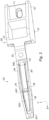
- FIGS. 1 to 3 represent perspective views of a spacer element 1 of a device 100 according to the invention.
- the spacer element 1 has a base 10 comprising an oblong orifice 11 for a fixing screw (not shown) and an elongated guide body 12.
- the base 10 is extended by a connecting member 30.
- the connecting member 30 forms an elongation comprising a first portion 31 connecting the base 10 to an elastically deformable zone 32 and a second portion 33 extending the elastically deformable zone 32.
- an axis Z of the first element 1 of the device 100 is an axis transverse to an axis of elongation of the base 10.
- an axis X of the first element 1 of the device 100 is an axis of elongation of the second portion 33.
- a Y axis of the first element 1 of the device 100 is an axis perpendicular to the X and Z axes.
- the elastically deformable zone 32 of the connecting member 30 has a thickness along the Z axis which is low compared to a length along the X axis, thus allowing deformation of the connecting member by rotation along the Y axis.
- the second portion 33 is an elongation formed by two symmetrical arms 34 connected by a first end 340 to the elastically deformable zone 32 and between them to a second end 341.
- the second end 341 is a free end.
- the arms 34 define a space between them.
- Each arm 34 comprises a stop 35 positioned substantially in the middle of the arm 34 and extending along the Z axis.
- Each arm 34 has an arcuate shape between the second end 341 and the stop 35 such that a thickness of the arms 34 along the Z axis increases progressively from the second end 341 towards the stop 35.
- the first end 340 of the arms 34 is connected to a retaining member 40 extending along the axis X.
- the retaining member 40 has an elongated shape provided with a first end and a second free end.
- the first end of the retaining member 40 comprises an elastically deformable zone 41 whose thickness along the Z axis is small compared to a length along the X axis, thus allowing deformation of the retaining member 40 by rotation along the Y axis.
- the free end of the retaining member 40 is provided with a protrusion 42.
- the protrusion 42 has a contact side 420 and a retaining surface 421.
- the contact side 420 has a thickness along the Z axis which progressively increases from the free end towards a center of the retaining member 40.
- the retaining surface 421 is substantially perpendicular to the retaining member 40.
- the device 100 When the device 100 is installed on a vehicle as can be seen in the figures 4 And 5 , an operator inserts the guide body 12 of the base 10 of the spacer element 1 into an orifice (not shown) of a fixed part of a chassis of the vehicle. Then, the operator pivots the fixing screw so as to temporarily fix the spacer element 1 on the vehicle.
- the opening element 200 has an orifice 21 with a substantially rectangular section intended to cooperate with the spacer element 1.
- This orifice 21 has an edge 22 intended to act as a member for maintaining operation.
- the spacer element 1 of the device 100 is introduced into the orifice 21.
- the holding member 22 then comes into contact with the second end 341 of the second portion 33.
- the holding member 22 slides against the arcuate shape of each arm 34 so as to deform the second portion 33 at the elastically deformable zone 32.
- the holding member 22 also slides against the contact side 420 of the retaining member 40, deforms the retaining member 40 at the elastically deformable zone 41 and then comes into contact with the retaining surface 421.
- the holding member 22 is blocked in a half-open position between the stops 35 of the connecting member 30 on the one hand, and the protuberance 42 of the retaining member 40 on the other hand.
- the deformation of the connecting member 30 makes it possible to adapt the device 100 to a relative position of the opening element 200 with respect to a fixed part of the vehicle chassis.
- the retaining member 40 is then in a reference position relative to the holding member 22.
- the reference position is independent of the relative position of the opening element 200 relative to a fixed part of the vehicle chassis.
- the holding member 22 deforms the retaining member 40 at the elastically deformable zone 41 so as to release the holding member and place the opening element 200 in an open position.
- the retaining member 40 being in the reference position relative to the holding member 22, the opening force that the operator must exert is predefined by the dimension along the Z axis of the retaining surface 421 and the stiffness of the elastically deformable zone 41.
- the opening force is identical regardless of the relative position of the opening element 200 with respect to a fixed part of the vehicle chassis.
- the opening force is determined at the design of the device 100 and is identical regardless of the vehicle or the opening on which the device 100 is positioned.
Landscapes
- Engineering & Computer Science (AREA)
- Mechanical Engineering (AREA)
- Manufacturing & Machinery (AREA)
- Chemical & Material Sciences (AREA)
- Combustion & Propulsion (AREA)
- Transportation (AREA)
- Connection Of Plates (AREA)
- Lock And Its Accessories (AREA)
- Power-Operated Mechanisms For Wings (AREA)
- Closing And Opening Devices For Wings, And Checks For Wings (AREA)
- Motor Or Generator Frames (AREA)
Claims (13)
- Vorrichtung (100) zum Halten eines Öffnungselements (200) in einer halboffenen Position an einem festen Abschnitt einer Karosserie eines Kraftfahrzeugs, umfassend ein Abstandselement (1), das dazu vorgesehen ist, an einem festen Abschnitt der Karosserie des Fahrzeugs oder am Öffnungselement (200) befestigt zu werden, wobei das Abstandselement (1) eine Basis (10) umfasst, die zur Befestigung des Abstandselements (1) am festen Abschnitt oder am Öffnungselement (200) vorgesehen ist,
dadurch gekennzeichnet, dass das Abstandselement (1) Folgendes umfasst:- ein Verbindungselement (30), das an der Basis (10) angebracht ist und einen elastisch verformbaren Bereich (32) enthält, der dazu ausgestaltet ist, sich unter der Wirkung von Spannungen zu verformen, die von einem Halteelement ausgeübt werden, das von dem Öffnungselement (200) oder dem festen Abschnitt bereitgestellt wird,- ein Rückhalteelement (40), das an dem Verbindungselement (30) angebracht ist und einen elastisch verformbaren Bereich (41) enthält, der dazu ausgestaltet ist, sich unter der Wirkung von Spannungen zu verformen, die vom Halteelement ausgeübt werden. - Vorrichtung (100) zum Halten in einer halboffenen Position nach Anspruch 1, wobei der elastisch verformbare Bereich (32) des Verbindungselements (30) dazu bestimmt ist, das Schwenken des Verbindungselements (30) in Bezug auf eine Drehachse zu ermöglichen.
- Vorrichtung (100) zum Halten in einer halboffenen Position nach einem der vorhergehenden Ansprüche, wobei der elastisch verformbare Bereich (41) des Rückhalteelements (40) dazu bestimmt ist, das Schwenken des Rückhalteelements (40) in Bezug auf eine Drehachse zu ermöglichen.
- Vorrichtung (100) zum Halten in einer halboffenen Position nach den Ansprüchen 2 und 3, wobei die Drehachse des Verbindungselements (30) parallel zur Drehachse des Rückhalteelements (40) verläuft.
- Vorrichtung (100) zum Halten in einer halboffenen Position nach einem der vorhergehenden Ansprüche, wobei das Rückhalteelement (40) eine Verlängerung ist, die ein freies Ende enthält.
- Vorrichtung (100) zum Halten in einer halboffenen Position nach einem der vorhergehenden Ansprüche, wobei das Rückhalteelement (40) am freien Ende mindestens einen Vorsprung (42) aufweist.
- Vorrichtung (100) zum Halten in einer halboffenen Position nach einem der Ansprüche 5 oder 6, wobei der elastisch verformbare Bereich (41) des Rückhalteelements (40) an einem dem freien Ende gegenüberliegenden Ende positioniert ist.
- Vorrichtung (100) zum Halten in einer halboffenen Position nach einem der Ansprüche 5 oder 6, wobei der elastisch verformbare Bereich (41) des Rückhalteelements (40) im Wesentlichen in der Mitte der Verlängerung positioniert ist.
- Vorrichtung (100) zum Halten in einer halboffenen Position nach einem der vorhergehenden Ansprüche, wobei das Verbindungselement (30) eine Verlängerung ist, die ein freies Ende (341) enthält.
- Vorrichtung (100) zum Halten in einer halboffenen Position nach einem der vorhergehenden Ansprüche, wobei das Verbindungselement (30) mindestens einen Endanschlag (35) umfasst, der es ermöglicht, zu verhindern, dass das Öffnungselement (200) in eine vollständig geschlossene Position an der Karosserie des Fahrzeugs gelangt.
- Vorrichtung (100) zum Halten in einer halboffenen Position nach Anspruch 9, wobei der elastisch verformbare Bereich (32) des Verbindungselements (30) an einem Ende gegenüber dem freien Ende (341) positioniert ist.
- Vorrichtung (100) zum Halten in einer halboffenen Position nach Anspruch 9, wobei der elastisch verformbare Bereich (32) des Verbindungselements (30) im Wesentlichen in der Mitte der Verlängerung positioniert ist.
- Vorrichtung (100) zum Halten in einer halboffenen Position nach einem der Ansprüche 1 bis 12, dadurch gekennzeichnet, dass der elastisch verformbare Bereich (32) des Verbindungselements (30) derart ausgestaltet ist, dass er einen unterschiedlichen Widerstand gegen Spannungen, die von dem Halteelement ausgeübt werden, das von dem festen Abschnitt oder dem Öffnungselement (200) bereitgestellt wird, als der elastisch verformbaren Bereich (41) des Rückhalteelements (40) bietet.
Applications Claiming Priority (2)
| Application Number | Priority Date | Filing Date | Title |
|---|---|---|---|
| FR1759825A FR3072706B1 (fr) | 2017-10-19 | 2017-10-19 | Dispositif d’ecartement d’un element ouvrant par rapport a un element fixe, notamment d’un vehicule automobile |
| PCT/FR2018/052455 WO2019077224A1 (fr) | 2017-10-19 | 2018-10-04 | Dispositif d'écartement d'un élément ouvrant par rapport à un élément fixe, notamment d'un véhicule automobile |
Publications (3)
| Publication Number | Publication Date |
|---|---|
| EP3697997A1 EP3697997A1 (de) | 2020-08-26 |
| EP3697997C0 EP3697997C0 (de) | 2024-11-13 |
| EP3697997B1 true EP3697997B1 (de) | 2024-11-13 |
Family
ID=61003138
Family Applications (1)
| Application Number | Title | Priority Date | Filing Date |
|---|---|---|---|
| EP18793250.4A Active EP3697997B1 (de) | 2017-10-19 | 2018-10-04 | Vorrichtung zur abstandsherstellung von einem öffnungselement zu einem stationären element, insbesondere zu einem kraftfahrzeug |
Country Status (9)
| Country | Link |
|---|---|
| US (1) | US20200291701A1 (de) |
| EP (1) | EP3697997B1 (de) |
| BR (1) | BR112020006531A2 (de) |
| CA (1) | CA3079440A1 (de) |
| ES (1) | ES3008915T3 (de) |
| FR (1) | FR3072706B1 (de) |
| MX (1) | MX2020004294A (de) |
| RU (1) | RU2020112707A (de) |
| WO (1) | WO2019077224A1 (de) |
Family Cites Families (11)
| Publication number | Priority date | Publication date | Assignee | Title |
|---|---|---|---|---|
| US6360407B1 (en) * | 2000-08-30 | 2002-03-26 | Daimlerchrysler Corporation | Spring steel door hold-open tool |
| US6656278B2 (en) * | 2001-07-23 | 2003-12-02 | Howard Baisch | Door positioning article |
| FR2892140B1 (fr) * | 2005-10-17 | 2008-01-11 | Exsto Soc Par Actions Simplifi | Dispositif d'ecartement et de verrouillage provisoire d'un element ouvrant sur un element fixe |
| FR2893300B1 (fr) * | 2005-11-15 | 2008-02-01 | Exsto Soc Par Actions Simplifi | Dispositif d'ecartement securise a l'arrachement |
| FR2893969B1 (fr) * | 2005-11-30 | 2013-03-29 | Exsto | Dispositif de verrouillage |
| FR2920804B1 (fr) * | 2007-09-12 | 2009-12-04 | Exsto | Dispositif d'ecartement provisoire muni de moyens de verrouillage |
| DE102008009589B4 (de) * | 2008-02-15 | 2020-11-12 | Volkswagen Ag | Lackbetriebsmittel |
| FR2978473B1 (fr) * | 2011-07-29 | 2013-08-09 | Exsto Thermoplastics | Dispositif de fermeture provisoire bi-matieres d'un element ouvrant sur un element fixe d'une carrosserie d'un vehicule automobile |
| HUE041508T2 (hu) * | 2013-04-16 | 2019-05-28 | Exsto Thermoplastics | Szerkezet egy gépjármûajtó megtartására egy félig nyitott helyzetben |
| FR3004412B1 (fr) | 2013-04-16 | 2016-12-09 | Exsto Thermoplastics | Interface de protection d’un dispositif de fermeture provisoire |
| FR3007056A1 (fr) * | 2013-06-13 | 2014-12-19 | Boulay Plastiques | Dispositif de fermeture provisoire d'un element ouvrant sur un element support |
-
2017
- 2017-10-19 FR FR1759825A patent/FR3072706B1/fr active Active
-
2018
- 2018-10-04 RU RU2020112707A patent/RU2020112707A/ru unknown
- 2018-10-04 EP EP18793250.4A patent/EP3697997B1/de active Active
- 2018-10-04 US US16/652,439 patent/US20200291701A1/en not_active Abandoned
- 2018-10-04 CA CA3079440A patent/CA3079440A1/fr active Pending
- 2018-10-04 MX MX2020004294A patent/MX2020004294A/es unknown
- 2018-10-04 ES ES18793250T patent/ES3008915T3/es active Active
- 2018-10-04 WO PCT/FR2018/052455 patent/WO2019077224A1/fr not_active Ceased
- 2018-10-04 BR BR112020006531-5A patent/BR112020006531A2/pt not_active Application Discontinuation
Also Published As
| Publication number | Publication date |
|---|---|
| WO2019077224A1 (fr) | 2019-04-25 |
| ES3008915T3 (en) | 2025-03-25 |
| US20200291701A1 (en) | 2020-09-17 |
| FR3072706A1 (fr) | 2019-04-26 |
| RU2020112707A (ru) | 2021-11-19 |
| MX2020004294A (es) | 2020-08-13 |
| RU2020112707A3 (de) | 2022-01-13 |
| EP3697997A1 (de) | 2020-08-26 |
| EP3697997C0 (de) | 2024-11-13 |
| FR3072706B1 (fr) | 2019-10-18 |
| BR112020006531A2 (pt) | 2020-10-06 |
| CA3079440A1 (fr) | 2019-04-25 |
Similar Documents
| Publication | Publication Date | Title |
|---|---|---|
| EP0199614B1 (de) | Klammerähnliches Befestigungsmittel | |
| FR3066240A1 (fr) | Support et ensemble support | |
| FR3057806A1 (fr) | Enjoliveur de roue d'un vehicule, notamment automobile | |
| EP2258955B1 (de) | Mutternklemmvorrichtung, geeignet zur Positionierung am Rand einer Unterlage wie etwa einer Platte | |
| WO2018146416A1 (fr) | Dispositif de maintien en position entrebâillée d'un ouvrant sur un élément fixe d'une caisse d'un véhicule | |
| EP3697997B1 (de) | Vorrichtung zur abstandsherstellung von einem öffnungselement zu einem stationären element, insbesondere zu einem kraftfahrzeug | |
| EP2730487B1 (de) | Haltebauteil für zwei gegeneinander befestigte Karosserieelemente eines Kraftfahrzeugs | |
| EP2883711B1 (de) | Zeichenzirkel mit positionsfixierung | |
| EP3045357A1 (de) | Abdeckung eines scheibenwischers, die für die abdeckung des endteils eines scheibenwischerarms konfiguriert ist | |
| EP0565443A1 (de) | Scheibenwischanlage mit Windableiter | |
| FR2951286A1 (fr) | Monture de lunette | |
| EP3434536B1 (de) | Befestigungsvorrichtung für ein gestängesystem zur betätigung von scheibenwischern | |
| EP2446155B1 (de) | Plastikmutter-befestigungvorrichtung | |
| EP1231422B1 (de) | Verfahren zur Herstellung einer unverlierbaren Schraube, Fixierungstellringe für Rohrleitungen und Gebrauch von dem Prozess, die Stellringe herzustellen | |
| FR2796427A1 (fr) | Dispositif de premontage d'un ecrou pour ensemble de fixation du type vis-ecrou | |
| FR2909153A1 (fr) | Dispositif pour la fixation d'un element | |
| EP3312053B1 (de) | Befestigungsanordnung für aufklappbegrenzung einer hinteren ablage auf der heckklappe eines kraftfahrzeugs | |
| FR2945844A1 (fr) | Dispositif de fixation d'au moins une deuxieme piece sur une premiere piece. | |
| WO2019239031A1 (fr) | Bord de panneau conforme pour la réception d'une pince a écrou | |
| EP2198181B1 (de) | Vorrichtung zur sicheren montage eines antivibrationsaktuators an einem automobil | |
| FR3072316A1 (fr) | Outil equipe d'un dispositif de blocage en au moins une position d'une partie mobile de l'outil | |
| FR2846617A1 (fr) | Adaptateur pour monture standard de balai d'essuie glace | |
| FR3063950A1 (fr) | Capot, dispositif de connexion pour le montage d’un balai d’essuie-glace sur un bras d’essuie-glace et systeme d’essuyage correspondants | |
| FR3113268A1 (fr) | Dispositif de maintien d’une canalisation d’alimentation en produit lave-glace | |
| EP1701045A1 (de) | Verbindungsvorrichtung zum Verbinden eines Verbindungselements auf einem festen Träger |
Legal Events
| Date | Code | Title | Description |
|---|---|---|---|
| STAA | Information on the status of an ep patent application or granted ep patent |
Free format text: STATUS: UNKNOWN |
|
| STAA | Information on the status of an ep patent application or granted ep patent |
Free format text: STATUS: THE INTERNATIONAL PUBLICATION HAS BEEN MADE |
|
| PUAI | Public reference made under article 153(3) epc to a published international application that has entered the european phase |
Free format text: ORIGINAL CODE: 0009012 |
|
| STAA | Information on the status of an ep patent application or granted ep patent |
Free format text: STATUS: REQUEST FOR EXAMINATION WAS MADE |
|
| 17P | Request for examination filed |
Effective date: 20200407 |
|
| AK | Designated contracting states |
Kind code of ref document: A1 Designated state(s): AL AT BE BG CH CY CZ DE DK EE ES FI FR GB GR HR HU IE IS IT LI LT LU LV MC MK MT NL NO PL PT RO RS SE SI SK SM TR |
|
| AX | Request for extension of the european patent |
Extension state: BA ME |
|
| DAV | Request for validation of the european patent (deleted) | ||
| DAX | Request for extension of the european patent (deleted) | ||
| GRAP | Despatch of communication of intention to grant a patent |
Free format text: ORIGINAL CODE: EPIDOSNIGR1 |
|
| STAA | Information on the status of an ep patent application or granted ep patent |
Free format text: STATUS: GRANT OF PATENT IS INTENDED |
|
| INTG | Intention to grant announced |
Effective date: 20240619 |
|
| GRAS | Grant fee paid |
Free format text: ORIGINAL CODE: EPIDOSNIGR3 |
|
| GRAA | (expected) grant |
Free format text: ORIGINAL CODE: 0009210 |
|
| STAA | Information on the status of an ep patent application or granted ep patent |
Free format text: STATUS: THE PATENT HAS BEEN GRANTED |
|
| AK | Designated contracting states |
Kind code of ref document: B1 Designated state(s): AL AT BE BG CH CY CZ DE DK EE ES FI FR GB GR HR HU IE IS IT LI LT LU LV MC MK MT NL NO PL PT RO RS SE SI SK SM TR |
|
| REG | Reference to a national code |
Ref country code: GB Ref legal event code: FG4D Free format text: NOT ENGLISH |
|
| REG | Reference to a national code |
Ref country code: CH Ref legal event code: EP |
|
| REG | Reference to a national code |
Ref country code: DE Ref legal event code: R096 Ref document number: 602018076564 Country of ref document: DE |
|
| REG | Reference to a national code |
Ref country code: IE Ref legal event code: FG4D Free format text: LANGUAGE OF EP DOCUMENT: FRENCH |
|
| U01 | Request for unitary effect filed |
Effective date: 20241211 |
|
| U07 | Unitary effect registered |
Designated state(s): AT BE BG DE DK EE FI FR IT LT LU LV MT NL PT RO SE SI Effective date: 20241219 |
|
| REG | Reference to a national code |
Ref country code: ES Ref legal event code: FG2A Ref document number: 3008915 Country of ref document: ES Kind code of ref document: T3 Effective date: 20250325 |
|
| REG | Reference to a national code |
Ref country code: SK Ref legal event code: T3 Ref document number: E 45879 Country of ref document: SK |
|
| PG25 | Lapsed in a contracting state [announced via postgrant information from national office to epo] |
Ref country code: HR Free format text: LAPSE BECAUSE OF FAILURE TO SUBMIT A TRANSLATION OF THE DESCRIPTION OR TO PAY THE FEE WITHIN THE PRESCRIBED TIME-LIMIT Effective date: 20241113 Ref country code: IS Free format text: LAPSE BECAUSE OF FAILURE TO SUBMIT A TRANSLATION OF THE DESCRIPTION OR TO PAY THE FEE WITHIN THE PRESCRIBED TIME-LIMIT Effective date: 20250313 |
|
| PG25 | Lapsed in a contracting state [announced via postgrant information from national office to epo] |
Ref country code: NO Free format text: LAPSE BECAUSE OF FAILURE TO SUBMIT A TRANSLATION OF THE DESCRIPTION OR TO PAY THE FEE WITHIN THE PRESCRIBED TIME-LIMIT Effective date: 20250213 |
|
| PG25 | Lapsed in a contracting state [announced via postgrant information from national office to epo] |
Ref country code: GR Free format text: LAPSE BECAUSE OF FAILURE TO SUBMIT A TRANSLATION OF THE DESCRIPTION OR TO PAY THE FEE WITHIN THE PRESCRIBED TIME-LIMIT Effective date: 20250214 |
|
| PG25 | Lapsed in a contracting state [announced via postgrant information from national office to epo] |
Ref country code: PL Free format text: LAPSE BECAUSE OF FAILURE TO SUBMIT A TRANSLATION OF THE DESCRIPTION OR TO PAY THE FEE WITHIN THE PRESCRIBED TIME-LIMIT Effective date: 20241113 |
|
| PG25 | Lapsed in a contracting state [announced via postgrant information from national office to epo] |
Ref country code: RS Free format text: LAPSE BECAUSE OF FAILURE TO SUBMIT A TRANSLATION OF THE DESCRIPTION OR TO PAY THE FEE WITHIN THE PRESCRIBED TIME-LIMIT Effective date: 20250213 |
|
| PG25 | Lapsed in a contracting state [announced via postgrant information from national office to epo] |
Ref country code: SM Free format text: LAPSE BECAUSE OF FAILURE TO SUBMIT A TRANSLATION OF THE DESCRIPTION OR TO PAY THE FEE WITHIN THE PRESCRIBED TIME-LIMIT Effective date: 20241113 |
|
| PLBE | No opposition filed within time limit |
Free format text: ORIGINAL CODE: 0009261 |
|
| STAA | Information on the status of an ep patent application or granted ep patent |
Free format text: STATUS: NO OPPOSITION FILED WITHIN TIME LIMIT |
|
| U20 | Renewal fee for the european patent with unitary effect paid |
Year of fee payment: 8 Effective date: 20250829 |
|
| PGFP | Annual fee paid to national office [announced via postgrant information from national office to epo] |
Ref country code: TR Payment date: 20250916 Year of fee payment: 8 |
|
| PGFP | Annual fee paid to national office [announced via postgrant information from national office to epo] |
Ref country code: GB Payment date: 20250829 Year of fee payment: 8 |
|
| 26N | No opposition filed |
Effective date: 20250814 |
|
| PGFP | Annual fee paid to national office [announced via postgrant information from national office to epo] |
Ref country code: CZ Payment date: 20250917 Year of fee payment: 8 |
|
| PGFP | Annual fee paid to national office [announced via postgrant information from national office to epo] |
Ref country code: SK Payment date: 20250916 Year of fee payment: 8 |
|
| PGFP | Annual fee paid to national office [announced via postgrant information from national office to epo] |
Ref country code: ES Payment date: 20260114 Year of fee payment: 8 |