EP3698209B1 - Dispositifs d'affichage comprenant des composés photochromiques-dichroïques et des composés dichroïques - Google Patents
Dispositifs d'affichage comprenant des composés photochromiques-dichroïques et des composés dichroïques Download PDFInfo
- Publication number
- EP3698209B1 EP3698209B1 EP18800766.0A EP18800766A EP3698209B1 EP 3698209 B1 EP3698209 B1 EP 3698209B1 EP 18800766 A EP18800766 A EP 18800766A EP 3698209 B1 EP3698209 B1 EP 3698209B1
- Authority
- EP
- European Patent Office
- Prior art keywords
- dichroic compound
- photochromic
- display element
- coating
- layer
- Prior art date
- Legal status (The legal status is an assumption and is not a legal conclusion. Google has not performed a legal analysis and makes no representation as to the accuracy of the status listed.)
- Active
Links
Images
Classifications
-
- G—PHYSICS
- G02—OPTICS
- G02F—OPTICAL DEVICES OR ARRANGEMENTS FOR THE CONTROL OF LIGHT BY MODIFICATION OF THE OPTICAL PROPERTIES OF THE MEDIA OF THE ELEMENTS INVOLVED THEREIN; NON-LINEAR OPTICS; FREQUENCY-CHANGING OF LIGHT; OPTICAL LOGIC ELEMENTS; OPTICAL ANALOGUE/DIGITAL CONVERTERS
- G02F1/00—Devices or arrangements for the control of the intensity, colour, phase, polarisation or direction of light arriving from an independent light source, e.g. switching, gating or modulating; Non-linear optics
- G02F1/01—Devices or arrangements for the control of the intensity, colour, phase, polarisation or direction of light arriving from an independent light source, e.g. switching, gating or modulating; Non-linear optics for the control of the intensity, phase, polarisation or colour
- G02F1/0126—Opto-optical modulation, i.e. control of one light beam by another light beam, not otherwise provided for in this subclass
-
- C—CHEMISTRY; METALLURGY
- C03—GLASS; MINERAL OR SLAG WOOL
- C03C—CHEMICAL COMPOSITION OF GLASSES, GLAZES OR VITREOUS ENAMELS; SURFACE TREATMENT OF GLASS; SURFACE TREATMENT OF FIBRES OR FILAMENTS MADE FROM GLASS, MINERALS OR SLAGS; JOINING GLASS TO GLASS OR OTHER MATERIALS
- C03C17/00—Surface treatment of glass, not in the form of fibres or filaments, by coating
- C03C17/28—Surface treatment of glass, not in the form of fibres or filaments, by coating with organic material
- C03C17/32—Surface treatment of glass, not in the form of fibres or filaments, by coating with organic material with synthetic or natural resins
-
- C—CHEMISTRY; METALLURGY
- C03—GLASS; MINERAL OR SLAG WOOL
- C03C—CHEMICAL COMPOSITION OF GLASSES, GLAZES OR VITREOUS ENAMELS; SURFACE TREATMENT OF GLASS; SURFACE TREATMENT OF FIBRES OR FILAMENTS MADE FROM GLASS, MINERALS OR SLAGS; JOINING GLASS TO GLASS OR OTHER MATERIALS
- C03C23/00—Other surface treatment of glass not in the form of fibres or filaments
- C03C23/0005—Other surface treatment of glass not in the form of fibres or filaments by irradiation
- C03C23/006—Other surface treatment of glass not in the form of fibres or filaments by irradiation by plasma or corona discharge
-
- C—CHEMISTRY; METALLURGY
- C09—DYES; PAINTS; POLISHES; NATURAL RESINS; ADHESIVES; COMPOSITIONS NOT OTHERWISE PROVIDED FOR; APPLICATIONS OF MATERIALS NOT OTHERWISE PROVIDED FOR
- C09K—MATERIALS FOR MISCELLANEOUS APPLICATIONS, NOT PROVIDED FOR ELSEWHERE
- C09K9/00—Tenebrescent materials, i.e. materials for which the range of wavelengths for energy absorption is changed as a result of excitation by some form of energy
- C09K9/02—Organic tenebrescent materials
-
- G—PHYSICS
- G02—OPTICS
- G02B—OPTICAL ELEMENTS, SYSTEMS OR APPARATUS
- G02B5/00—Optical elements other than lenses
- G02B5/20—Filters
- G02B5/22—Absorbing filters
- G02B5/23—Photochromic filters
-
- G—PHYSICS
- G02—OPTICS
- G02B—OPTICAL ELEMENTS, SYSTEMS OR APPARATUS
- G02B5/00—Optical elements other than lenses
- G02B5/30—Polarising elements
- G02B5/3025—Polarisers, i.e. arrangements capable of producing a definite output polarisation state from an unpolarised input state
-
- G—PHYSICS
- G02—OPTICS
- G02B—OPTICAL ELEMENTS, SYSTEMS OR APPARATUS
- G02B5/00—Optical elements other than lenses
- G02B5/30—Polarising elements
- G02B5/3083—Birefringent or phase retarding elements
-
- G—PHYSICS
- G02—OPTICS
- G02F—OPTICAL DEVICES OR ARRANGEMENTS FOR THE CONTROL OF LIGHT BY MODIFICATION OF THE OPTICAL PROPERTIES OF THE MEDIA OF THE ELEMENTS INVOLVED THEREIN; NON-LINEAR OPTICS; FREQUENCY-CHANGING OF LIGHT; OPTICAL LOGIC ELEMENTS; OPTICAL ANALOGUE/DIGITAL CONVERTERS
- G02F1/00—Devices or arrangements for the control of the intensity, colour, phase, polarisation or direction of light arriving from an independent light source, e.g. switching, gating or modulating; Non-linear optics
- G02F1/01—Devices or arrangements for the control of the intensity, colour, phase, polarisation or direction of light arriving from an independent light source, e.g. switching, gating or modulating; Non-linear optics for the control of the intensity, phase, polarisation or colour
- G02F1/13—Devices or arrangements for the control of the intensity, colour, phase, polarisation or direction of light arriving from an independent light source, e.g. switching, gating or modulating; Non-linear optics for the control of the intensity, phase, polarisation or colour based on liquid crystals, e.g. single liquid crystal display cells
- G02F1/133—Constructional arrangements; Operation of liquid crystal cells; Circuit arrangements
- G02F1/1333—Constructional arrangements; Manufacturing methods
- G02F1/1335—Structural association of cells with optical devices, e.g. polarisers or reflectors
- G02F1/133528—Polarisers
-
- G—PHYSICS
- G02—OPTICS
- G02F—OPTICAL DEVICES OR ARRANGEMENTS FOR THE CONTROL OF LIGHT BY MODIFICATION OF THE OPTICAL PROPERTIES OF THE MEDIA OF THE ELEMENTS INVOLVED THEREIN; NON-LINEAR OPTICS; FREQUENCY-CHANGING OF LIGHT; OPTICAL LOGIC ELEMENTS; OPTICAL ANALOGUE/DIGITAL CONVERTERS
- G02F1/00—Devices or arrangements for the control of the intensity, colour, phase, polarisation or direction of light arriving from an independent light source, e.g. switching, gating or modulating; Non-linear optics
- G02F1/01—Devices or arrangements for the control of the intensity, colour, phase, polarisation or direction of light arriving from an independent light source, e.g. switching, gating or modulating; Non-linear optics for the control of the intensity, phase, polarisation or colour
- G02F1/13—Devices or arrangements for the control of the intensity, colour, phase, polarisation or direction of light arriving from an independent light source, e.g. switching, gating or modulating; Non-linear optics for the control of the intensity, phase, polarisation or colour based on liquid crystals, e.g. single liquid crystal display cells
- G02F1/133—Constructional arrangements; Operation of liquid crystal cells; Circuit arrangements
- G02F1/1333—Constructional arrangements; Manufacturing methods
- G02F1/1337—Surface-induced orientation of the liquid crystal molecules, e.g. by alignment layers
- G02F1/133711—Surface-induced orientation of the liquid crystal molecules, e.g. by alignment layers by organic films, e.g. polymeric films
-
- C—CHEMISTRY; METALLURGY
- C03—GLASS; MINERAL OR SLAG WOOL
- C03C—CHEMICAL COMPOSITION OF GLASSES, GLAZES OR VITREOUS ENAMELS; SURFACE TREATMENT OF GLASS; SURFACE TREATMENT OF FIBRES OR FILAMENTS MADE FROM GLASS, MINERALS OR SLAGS; JOINING GLASS TO GLASS OR OTHER MATERIALS
- C03C2218/00—Methods for coating glass
- C03C2218/30—Aspects of methods for coating glass not covered above
- C03C2218/31—Pre-treatment
-
- C—CHEMISTRY; METALLURGY
- C03—GLASS; MINERAL OR SLAG WOOL
- C03C—CHEMICAL COMPOSITION OF GLASSES, GLAZES OR VITREOUS ENAMELS; SURFACE TREATMENT OF GLASS; SURFACE TREATMENT OF FIBRES OR FILAMENTS MADE FROM GLASS, MINERALS OR SLAGS; JOINING GLASS TO GLASS OR OTHER MATERIALS
- C03C2218/00—Methods for coating glass
- C03C2218/30—Aspects of methods for coating glass not covered above
- C03C2218/32—After-treatment
-
- C—CHEMISTRY; METALLURGY
- C03—GLASS; MINERAL OR SLAG WOOL
- C03C—CHEMICAL COMPOSITION OF GLASSES, GLAZES OR VITREOUS ENAMELS; SURFACE TREATMENT OF GLASS; SURFACE TREATMENT OF FIBRES OR FILAMENTS MADE FROM GLASS, MINERALS OR SLAGS; JOINING GLASS TO GLASS OR OTHER MATERIALS
- C03C4/00—Compositions for glass with special properties
- C03C4/04—Compositions for glass with special properties for photosensitive glass
- C03C4/06—Compositions for glass with special properties for photosensitive glass for phototropic or photochromic glass
-
- G—PHYSICS
- G02—OPTICS
- G02F—OPTICAL DEVICES OR ARRANGEMENTS FOR THE CONTROL OF LIGHT BY MODIFICATION OF THE OPTICAL PROPERTIES OF THE MEDIA OF THE ELEMENTS INVOLVED THEREIN; NON-LINEAR OPTICS; FREQUENCY-CHANGING OF LIGHT; OPTICAL LOGIC ELEMENTS; OPTICAL ANALOGUE/DIGITAL CONVERTERS
- G02F2202/00—Materials and properties
- G02F2202/14—Materials and properties photochromic
-
- H—ELECTRICITY
- H10—SEMICONDUCTOR DEVICES; ELECTRIC SOLID-STATE DEVICES NOT OTHERWISE PROVIDED FOR
- H10H—INORGANIC LIGHT-EMITTING SEMICONDUCTOR DEVICES HAVING POTENTIAL BARRIERS
- H10H29/00—Integrated devices, or assemblies of multiple devices, comprising at least one light-emitting semiconductor element covered by group H10H20/00
- H10H29/10—Integrated devices comprising at least one light-emitting semiconductor component covered by group H10H20/00
- H10H29/14—Integrated devices comprising at least one light-emitting semiconductor component covered by group H10H20/00 comprising multiple light-emitting semiconductor components
- H10H29/142—Two-dimensional arrangements, e.g. asymmetric LED layout
-
- H—ELECTRICITY
- H10—SEMICONDUCTOR DEVICES; ELECTRIC SOLID-STATE DEVICES NOT OTHERWISE PROVIDED FOR
- H10K—ORGANIC ELECTRIC SOLID-STATE DEVICES
- H10K59/00—Integrated devices, or assemblies of multiple devices, comprising at least one organic light-emitting element covered by group H10K50/00
- H10K59/10—OLED displays
- H10K59/12—Active-matrix OLED [AMOLED] displays
Definitions
- the present invention is directed towards display elements and devices comprising photochromic-dichroic compounds and dichroic compounds.
- Sunlight readability may be improved in a number of ways.
- One solution is to actively increase the backlight intensity by adding more cold-cathode-fluorescent-lamp (CCFL) backlight tubes.
- CCFL cold-cathode-fluorescent-lamp
- a second approach is to passively increase backlight intensity by adding brightness-enhancement films to the optical stack of the display screen. While avoiding most of the drawbacks of the active approach, this solution only increases brightness by a factor of about two, which is insufficient to solve the sunlight readability problem.
- a third solution is the minimization of reflected light, such as through the use of anti-reflective coatings and films and circular polarizers. Each of these solutions may be combined with others to optimize the desired effect.
- a circular polarizer is an assembly of a conventional linearly polarizing element and a quarter wave retarder.
- the axis of the retarder is oriented at 45 degrees with respect to the axis of the linear polarizer.
- Circular polarizers have traditionally been used for their antireflective properties. In such applications, when light is reflected back from a specular surface through the retarder, the plane of polarization is rotated 90 degrees with respect to the original orientation so the linear polarizer blocks the returning reflected light.
- the circular polarizer must absorb a large amount of the transmitted radiation, typically about 60% of the transmitted radiation is absorbed.
- US 2014/078583 A1 discloses a prior art display device comprising a photochromic-dichroic compound.
- a display element comprising a photochromic-dichroic compound and a dichroic compound, the display element having a first absorption state and a second absorption state and being operable for switching from the first absorption state to the second absorption state in response to actinic radiation and to revert back to the first absorption state in response to actinic radiation and/or thermal energy, wherein the first absorption state has a transmittance percentage of 50% to 80%, and the second absorption state has a transmittance percentage of 10% to 50%.
- a display device comprising the display element comprising a photochromic-dichroic compound and a dichroic compound, the display element having a first absorption state and a second absorption state and being operable for switching from the first absorption state to the second absorption state in response to actinic radiation and to revert back to the first absorption state in response to actinic radiation and/or thermal energy, wherein the first absorption state has a transmittance percentage of 50% to 80%, and the second absorption state has a transmittance percentage of 10% to 50%.
- the present invention is directed to a display element comprising a photochromic-dichroic compound and a dichroic compound, the display element having a first absorption state and a second absorption state and being operable for switching from the first absorption state to the second absorption state in response to actinic radiation and to revert back to the first absorption state in response to actinic radiation and/or thermal energy, wherein the first absorption state has a transmittance percentage of 50% to 80%, and the second absorption state has a transmittance percentage of 10% to 50%.
- the display element comprises a photochromic-dichroic compound.
- the photochromic-dichroic compound has a first absorption state and a second absorption state, wherein the photochromic-dichroic material switches from the first state to the second state in response to actinic radiation, reverting back to the first state in response to actinic and/or thermal energy, and may demonstrate linear polarization both of the first state and the second state.
- photochromic-dichroic means displaying both photochromic and dichroic (i.e., linearly polarizing) properties under certain conditions, which properties are at least detectible by instrumentation.
- photochromic-dichroic compounds are compounds displaying both photochromic and dichroic (i.e., linearly polarizing) properties under certain conditions, which properties are at least detectible by instrumentation.
- linearly polarize means to confine the vibrations of the electric vector of light waves to one direction.
- photochromic-dichroic compounds have an absorption spectrum for at least visible radiation that varies in response to at least actinic radiation and are capable of absorbing one of two orthogonal plane polarized components of at least transmitted radiation more strongly than the other.
- the display element may have an absorption spectrum for at least visible radiation that varies in response to at least actinic radiation and may be capable of absorbing one of two orthogonal plane polarized components of at least transmitted radiation more strongly than the other.
- the photochromic-dichroic compound of the display element may be non-polarizing in the first state (that is, the photochromic-dichroic compound will not confine the vibrations of the electric vector of light waves to one direction) and linearly polarizing transmitted radiation in the second state.
- transmitted radiation refers to radiation that is passed through at least a portion of an object.
- the transmitted radiation can be ultraviolet radiation, visible radiation, or a combination thereof.
- the photochromic-dichroic material may be non-polarizing in the first state and linearly polarizing transmitted ultraviolet radiation, transmitted visible radiation, or a combination thereof in the second state.
- the photochromic-dichroic compounds disclosed herein may be thermally reversible. That is, the photochromic-dichroic compounds can switch from a first state to a second state in response to actinic radiation and revert back to the first state in response to thermal energy.
- Non-limiting examples of photochromic-dichroic compounds suitable for use in the display element disclosed herein include the compounds listed below and the compounds described in U.S. Pat No. 7,256,921 in column 19, line 26 to column 22, line 47, including:
- the photochromic-dichroic compounds may comprise: (a) at least one photochromic group (PC) chosen from pyrans, oxazines, and fulgides; and (b) at least one lengthening agent attached to the photochromic group, wherein the lengthening agent (L) is represented by the following Formula I (which is described in detail below): -[S 1 ] c -[Q 1 -[S 2 ] d ] d' -[Q 2 -[S 3 ] e ] e' -[Q 3 -[S 4 ] f ] f' -S 5 -P
- Formula I which is described in detail below
- L can be directly bonded to PC as a substituent on PC, or L can be a substituent on another group (such as a group represented by R 1 , which is discussed below) that is directly bonded to PC (i.e., L is indirectly bonded to PC).
- L can be attached to PC so as to extend or lengthen PC in an activated state such that the absorption ratio of the extended PC (i.e., the photochromic compound) is enhanced as compared to PC alone.
- the location of attachment of L on PC may be chosen such that L lengthens PC in at least one of a direction parallel to and a direction perpendicular to a theoretical transitional dipole moment of the activated form of PC.
- the term "theoretical transitional dipole moment" refers to transient dipolar polarization created by interaction of electromagnetic radiation with the molecule. See, for example, IUPAC Compendium of Chemical Technology, 2nd Ed., International Union of Pure and Applied Chemistry (1997 ).
- each of Qi, Q 2 , and Q 3 may be independently chosen for each occurrence from: a divalent group chosen from an unsubstituted or a substituted aromatic group, an unsubstituted or a substituted alicyclic group, an unsubstituted or a substituted heterocyclic group, and mixtures thereof, wherein substituents are chosen from: a group represented by P (as set forth below), liquid crystal mesogens, halogen, poly(Ci-Cis alkoxy), Ci-Cis alkoxycarbonyl, Ci-Cis alkylcarbonyl, C 1 -C 18 alkoxycarbonyloxy, aryloxycarbonyloxy, perfluoro(C 1 -C 18 )alkoxy, perfluoro(C 1 -C 18 )alkoxycarbonyl, perfluoro(C 1 -C 18 )alkylcarbonyl, perfluoro(C 1 -C 18 )alkylamino
- Q 1 , Q 2 , and Q 3 may be independently chosen for each occurrence from a divalent group, such as an unsubstituted or a substituted aromatic group, unsubstituted or substituted heterocyclic group, and an unsubstituted or substituted alicyclic group.
- a divalent group such as an unsubstituted or a substituted aromatic group, unsubstituted or substituted heterocyclic group, and an unsubstituted or substituted alicyclic group.
- useful aromatic groups include: benzo, naphtho, phenanthro, biphenyl, tetrahydro naphtho, terphenyl, and anthracene.
- heterocyclic group means a compound having a ring of atoms, wherein at least one atom forming the ring is different than the other atoms forming the ring. Further, as used herein, the term heterocyclic group specifically excludes fused heterocyclic groups.
- heterocyclic groups from which Qi, Q 2 , and Q 3 may be chosen include: isosorbitol, dibenzofuro, dibenzothieno, benzofuro, benzothieno, thieno, furo, dioxino, carbazolo, anthranilyl, azepinyl, benzoxazolyl, diazepinyl, dioazlyl, imidazolidinyl, imidazolyl, imidazolinyl, indazolyl, indoleninyl, indolinyl, indolizinyl, indolyl, indoxazinyl, isobenzazolyl, isoindolyl, isooxazolyl, isooxazyl, isopyrroyl, isoquinolyl, isothiazolyl, morpholino, morpholinyl, oxadiazolyl, oxathiazolyl, oxathiazyl
- Qi, Q 2 , and Q 3 may be chosen from mono- or di-substituted C 4 -C 18 spirobicyclic amine and C 4 -C 18 spirotricyclic amine.
- suitable substituents include aryl, C 1 -C 6 alkyl, C 1 -C 6 alkoxy or phenyl (C 1 -C 6 )alkyl.
- mono- or di-substituted spirobicyclic amines include: 2-azabicyclo[2.2.1]hept-2-yl; 3-azabicyclo[3.2.1]oct-3-yl; 2-azabicyclo[2.2.2]oct-2-yl; and 6-azabicyclo[3.2.2]nonan-6-yl.
- mono- or di-substituted tricyclic amines include: 2-azatricyclo[3.3.1.1 (3,7)]decan-2-yl; 4-benzyl-2-azatricyclo[3.3.1.1 (3,7)]decan-2-yl; 4-methoxy-6-methyl-2-azatricyclo[3.3.1.1 (3,7)]decan-2-yl; 4-azatricyclo[4.3.1.1(3,8)]undecan-4-yl; and 7-methyl-4-azatricyclo[4.3.1.1 (3,8)]undecan-4-yl.
- Examples of alicyclic groups from which Qi, Q 2 , and Q 3 may be chosen include, without limitation, cyclohexyl, cyclopropyl, norbomenyl, decalinyl, adamantanyl, bicycloctane, per-hydrofluorene, and cubanyl.
- each S 1 , S 2 , S 3 , S 4 , and S 5 can be independently chosen for each occurrence from a spacer unit chosen from:
- c, d, e, and f each may be independently chosen from an integer ranging from 1 to 20, inclusive; and d', e' and f each may be independently chosen from 0, 1, 2, 3, and 4, provided that the sum of d'+e'+f is at least 1.
- c, d, e, and f each may be independently chosen from an integer ranging from 1 to 20, inclusive; and d', e' and f each may be independently chosen from 0, 1, 2, 3, and 4, provided that the sum of d'+e'+f is at least 2.
- c, d, e, and f each may be independently chosen from an integer ranging from 1 to 20, inclusive; and d', e' and f each may be independently chosen from 0,1, 2, 3, and 4, provided that the sum of d'+e'+f is at least 3.
- c, d, e, and f each may be independently chosen from an integer ranging from 1 to 20, inclusive; and d', e' and f each may be independently chosen from 0, 1, 2, 3, and 4, provided that the sum of d'+e'+f is at least 1.
- P can be chosen from: hydroxy, amino, C 2 -C 18 alkenyl, C 2 -C 18 alkynyl, azido, silyl, siloxy, silylhydride, (tetrahydro-2H-pyran-2-yl)oxy, thio, isocyanato, thioisocyanato, acryloyloxy, methacryloyloxy, 2-(acryloyloxy)ethylcarbamyl, 2-(methacryloyloxy)ethylcarbamyl, aziridinyl, allyloxycarbonyloxy, epoxy, carboxylic acid, carboxylic ester, acryloylamino, methacryloylamino, aminocarbonyl, C 1 -C 18 alkyl aminocarbonyl, aminocarbonyl(C 1 -C 18 )alkyl, C 1 -C 18 alkyloxycarbonyloxy, halocarbonyl, hydrogen, aryl,
- the polymerizable group when P is a polymerizable group, the polymerizable group may be any functional group adapted to participate in a polymerization reaction.
- Examples of polymerization reactions include those described in the definition of "polymerization” in Hawley's Condensed Chemical Dictionary Thirteenth Edition, 1997, John Wiley & Sons, pages 901-902 .
- polymerization reactions include: “addition polymerization,” in which free radicals are the initiating agents that react with the double bond of a monomer by adding to it on one side at the same time producing a new free electron on the other side; “condensation polymerization,” in which two reacting molecules combine to form a larger molecule with elimination of a small molecule, such as a water molecule; and “oxidative coupling polymerization.”
- examples of polymerizable groups include hydroxy, acryloxy, methacryloxy, 2-(acryloxy)ethylcarbamyl, 2-(methacryloxy)ethylcarbamyl, isocyanate, aziridine, allylcarbonate, and epoxy, e.g., oxiranylmethyl.
- P may be chosen from a main-chain or a side-chain liquid crystal polymer and a liquid crystal mesogen.
- liquid crystal means rigid rod-like or disc-like liquid crystal molecules.
- main-chain liquid crystal polymer refers to a polymer having liquid crystal mesogens within the backbone (i.e., the main chain) structure of the polymer.
- side-chain liquid crystal polymer refers to a polymer having liquid crystal mesogens attached to the polymer at the side chains.
- the mesogens are made up of two or more aromatic rings that restrict the movement of a liquid crystal polymer.
- rod-like liquid crystal mesogens include without limitation: substituted or unsubstituted aromatic esters, substituted or unsubstituted linear aromatic compounds, and substituted or unsubstituted terphenyls.
- P may be chosen from a steroid, for example and without limitation, a cholesterolic compound.
- thermally reversible photochromic pyrans from which the photochromic group PC can be chosen include benzopyrans, naphthopyrans, e.g., naphtho[1,2-b]pyrans, naphtho[2,1-b]pyrans, indeno-fused naphthopyrans, such as those disclosed in U.S. Pat. No. 5,645,767 , and heterocyclic-fused naphthopyrans, such as those disclosed in U.S. Pat. Nos.
- spiro-9-fluoreno[1,2-b]pyrans phenanthropyrans; quinopyrans; fluoroanthenopyrans; spiropyrans, e.g., spiro(benzindoline)naphthopyrans, spiro(indoline)benzopyrans, spiro(indoline)naphthopyrans, spiro(indoline)quinopyrans and spiro(indoline)pyrans. More specific examples of naphthopyrans and the complementary organic photochromic substances are described in U.S. Pat. No.
- photochromic oxazines from which PC can be chosen include benzoxazines, naphthoxazines, and spiro-oxazines, e.g., spiro(indoline)naphthoxazines, spiro(indoline)pyridobenzoxazines, spiro(benzindoline)pyridobenzoxazines, spiro(benzindoline)naphthoxazines, spiro(indoline)benzoxazines, spiro(indoline)fluoranthenoxazine, and spiro(indoline)quinoxazine.
- benzoxazines naphthoxazines
- spiro-oxazines e.g., spiro(indoline)naphthoxazines, spiro(indoline)
- photochromic fulgides from which PC can be chosen include: fulgimides, and the 3-furyl and 3-thienyl fulgides and fulgimides, which are disclosed in U.S. Pat. No. 4,931,220 and mixtures of any of the aforementioned photochromic materials/compounds.
- the PCs can be linked to one another via linking group substituents on the individual PCs.
- the PCs can be polymerizable photochromic groups or photochromic groups that are adapted to be compatible with a host material ("compatibilized photochromic group").
- Examples of polymerizable photochromic groups from which PC may be chosen include those disclosed in U.S. Pat No. 6113814 .
- Examples of compatibilized photochromic groups from which PC may be chosen include those disclosed in U.S. Pat No. 6555028 .
- the photochromic compounds may further comprise at least one group represented by R 1 that is directly bonded to PC.
- the at least one lengthening agent (L) can be indirectly bonded to PC through the at least one group represented by R 1 . That is, L may be a substituent on at least one group R 1 that is bonded to PC.
- R 1 may be independently chosen for each occurrence from substituents disclosed in U.S. Pat No. 7,256,921 from column 26, line 60 to column 30, line 64.
- the photochromic-dichroic compounds of the present invention include the compounds and methods of preparation disclosed in U.S. Pat No. 7,256,921 from column 30, line 65 to column 66, line 60.
- the photochromic-dichroic compound may be at least partially aligned.
- the photochromic-dichroic compound of the present invention may comprise a plurality of photochromic-dichroic compounds.
- the photochromic-dichroic compounds may be chosen to complement one another to produce a desired color or hue.
- mixtures photochromic-dichroic compounds may be used to attain certain activated colors, such as a near neutral gray or near neutral brown. See, for example, U.S. Pat. No. 5,645,767 , column 12, line 66 to column 13, line 19, which describes the parameters that define neutral gray and brown colors.
- the photochromic-dichroic compound may comprise mixtures of photochromic-dichroic compounds having complementary linear polarization states.
- the photochromic-dichroic compounds may be chosen to have complementary linear polarization states over a desired range of wavelengths to produce a display element that is capable of polarizing light over the desired range of wavelengths.
- mixtures of complementary photochromic-dichroic compounds having essentially the same polarization states at the same wavelengths may be chosen to reinforce or enhance the overall linear polarization achieved.
- the photochromic-dichroic compound may comprise at least two at least partially aligned photochromic-dichroic compounds, wherein the photochromic-dichroic compounds have complementary colors and/or complementary linear polarization states.
- the display element comprises a dichroic compound.
- dichroic means capable of absorbing one of two orthogonal plane polarized components of transmitted radiation more strongly than the other.
- the dichroic compound has a fixed absorption state and a fixed degree of linear polarization that does not vary in response to exposure to actinic radiation.
- the dichroic compound may comprise a plurality of dichroic compounds. Additionally, as discussed below in more detail, the dichroic compound may be at least partially aligned.
- the dichroic compound may comprise azomethines, indigoids, thioindigoids, merocyanines, indans, quinophthalonic dyes, perylenes, phthaloperines, triphenodioxazines, indoloquinoxalines, imidazo-triazines, tetrazines, azo and (poly)azo dyes, benzoquinones, naphthoquinones, anthroquinone and (poly)anthroquinones, anthropyrimidinones, iodine and iodates.
- the dichroic compound may be a polymerizable dichroic compound.
- the dichroic compound may comprise at least one group that is capable of being polymerized (i.e., a "polymerizable group").
- the dichroic compound may comprise at least one alkoxy, polyalkoxy, alkyl, or polyalkyl substituent terminated with at least one polymerizable group.
- the dichroic compound may also comprise a plurality of these compounds.
- Suitable commercially available anthraquinone dyes include blue colored dyes Blue AB2, Blue AB3 and Blue AB4, the yellow colored dye Yellow AG1, the orange colored dye Orange AO1, the red colored dye Red AR1, and the cyan colored dye Cyan AC1, each of which is available from Nematel GmbH & Co. KG.
- Suitable commercially available azo dyes include the orange colored dye Orange AZO1, available from Nematel GmbH & Co. KG.
- the display element of the present invention has a first absorption state and a second absorption state and is operable for switching from the first absorption state to the second absorption state in response to actinic radiation and to revert back to the first absorption state in response to actinic radiation and/or thermal energy.
- the terms "first” and “second” are not intended to refer to any particular order or chronology, but instead refer to two different conditions or properties.
- the first state and the second state of the display element may differ with respect to at least one optical property, such as, but not limited to, the absorption/transmittance or linear polarization of visible and/or UV radiation.
- the display element may be adapted to have a different absorption spectrum in each of the first and second states.
- the display element can be adapted to have a first color in the first state and a second color in the second state.
- the display element may be adapted to have a first level of transmittance in the first state and a reduced level of transmittance in the second state.
- the properties of the first absorption state of the display element are generally dictated by the dichroic compound.
- the photochromic-dichroic compound present in the display element may linearly polarize transmitted radiation in the first absorption state, any amount of linear polarization provided by the photochromic-dichroic compound will be complementary to the more powerful absorption/linear polarization provided by the dichroic compound in the first absorption state.
- the properties of the second absorption state of the display element are generally dictated by the photochromic-dichroic compound and complemented by the dichroic compound. Upon activation of the photochromic-dichroic compound to achieve the second absorption state of the display element, the absorption/linear polarization provided by the photochromic-dichroic compound is more powerful than the dichroic compound.
- the first absorption state may have a transmittance percentage (%T) of at least 50%, such as at least 55%, such as at least 60%, and may have a transmittance percentage of no more than 80%, such as no more than 75%, such as no more than 70%.
- the first absorption state may have a transmittance percentage of 50% to 80%, such as 55% to 75%, such as 60% to 70%.
- the second absorption state may have a transmittance percentage of at least 10%, such as at least 12%, such as at least 15%, and may have a transmittance percentage of no more than 50%, such as no more than 45%, such as no more than 40%.
- the second absorption state may have a transmittance percentage of 10% to 50%, such as 12% to 45%, such as 15% to 40%.
- the terms "transmittance percentage” and “%T” refers to photopic transmission, and specifically refers to the fraction of incident electromagnetic power in the visible spectrum (wavelength of 390 nm to 700 nm) that is transmitted through a body, such as the display element, multiplied by 100%.
- the transmittance percentage may be measured by passing light through a body, recording the intensity using a spectrophotometer, dividing that value by the intensity of light when passed through a blank (i.e., no body) as measured by the spectrophotometer, and multiplying that value by 100%.
- Equation 1 P is intensity of light after passing through the body and P 0 is the intensity of light when passing through the blank.
- the first absorption state may have a linear polarization efficiency of at least 5%, such as at least 10%, such as at least 15%, and may have a linear polarization efficiency of no more than 70%, such as no more than 60%, such as no more than 50%.
- the first absorption state may have a linear polarization efficiency of 5% to 70%, such as 10% to 60%, such as 15% to 50%.
- the second absorption state may have a linear polarization efficiency of at least 55%, such as at least 65%, such as at least 70%, and may have a linear polarization efficiency of no more than 99.9%, such as no more than 90%, such as no more than 80%.
- the second absorption state may have a linear polarization efficiency of 55% to 99.9%, such as 65% to 90%, such as 70% to 80%.
- linear polarization efficiency refers to the percentage of incident electromagnetic radiation a body, such as the display element, transmits in the intended polarization state.
- a body having a linear polarization efficiency of 99% transmits 99% of incident electromagnetic radiation in the intended polarization state (e.g., p- or s-polarization) and 1% of incident electromagnetic radiation in the opposite polarization state.
- the weight ratio of dichroic compound to photochromic-dichroic compound may be at least 0.005:1, such as at least 0.010:1, such as at least 0.015:1, and may be no more than 0.150:1, such as no more than 0.120:1, such as no more than 0.090:1.
- the weight ratio of dichroic compound to photochromic-dichroic compound may be 0.005:1 to 0.150:1, such as 0.010:1 to 0.120:1, such as 0.015:1 to 0.090:1.
- the display element may comprise a substrate, a sheet, a coating, or any combination thereof.
- the display element may comprise a single substrate or sheet comprising a photochromic-dichroic compound and a dichroic compound.
- the display element may also comprise at least one substrate and/or at least one sheet, wherein the substrate or at least one sheet optionally includes at least one coating, and at least one of the substrate(s), sheet(s) and/or coating(s), if present, comprises a photochromic-dichroic compound and at least one of the substrate(s), sheet(s) and/or coating(s), if present, comprises a dichroic compound.
- any of the substrate(s), sheet(s) and/or coating(s) of the display element may comprise a photochromic-dichroic compound, a dichroic compound, or both a photochromic-dichroic compound and a dichroic compound. Additionally, multiple substrates, sheets and/or coatings of the display element may comprise a photochromic-dichroic compound, a dichroic compound, or combinations thereof. Further, the display element may comprise other layers that do not contain a photochromic-dichroic compound or a dichroic compound. Generally, substrates, sheets and coatings may each individually be referred to as a "layer.”
- the display element may comprise a substrate comprising the photochromic-dichroic compound and the dichroic compound.
- the display element may also comprise at least one sheet connected to a substrate, wherein at least one of the substrate and/or sheet(s) comprises at least one of the photochromic-dichroic compound and/or the dichroic compound.
- the display element may comprise at least one coating on a substrate, wherein at least one of the substrate and/or coating(s) comprises at least one of the photochromic-dichroic compound and/or the dichroic compound.
- the display element may comprise substrate connected to at least one sheet, further comprising at least one coating on at least one of the substrate and/or sheet(s), wherein at least one of the substrate, sheet(s) and/or coating(s) comprise at least one of the photochromic-dichroic compound and/or the dichroic compound. Additionally, any of the display elements described in this paragraph may comprise more than one substrate.
- the display element may comprise a sheet comprising the photochromic-dichroic compound and the dichroic compound.
- the display element may comprise multiple sheets, wherein at least one of the sheets comprises the photochromic-dichroic compound and the dichroic compound.
- the display element may comprise at least one sheet further comprising at least one coating on at least one sheet, wherein at least one of the sheet(s) and/or coating(s) comprise the photochromic-dichroic compound and the dichroic compound.
- the term "sheet” refers to a pre-formed film having a generally uniform thickness and is capable of self-support
- Examples of polymeric sheets that may be used in the display element include, without limitation, stretched polymer sheets, ordered liquid crystal polymer sheets, and photo-oriented polymer sheets.
- Examples of polymeric materials, other than liquid crystal materials and photo-orientation materials that may be used in forming polymeric sheets include without limitation, polyvinyl alcohol, polyvinyl chloride, polyurethane, polyacrylate, and polycaprolactam.
- the term “coating” means a supported film derived from a flowable composition, which may or may not have a uniform thickness, and specifically excludes polymeric sheets.
- the coating may comprise an at least partially ordered anisotropic material.
- anisotropic means having at least one property that differs in value when measured in at least one different direction.
- anisotropic materials are materials that have at least one property that differs in value when measured in at least one different direction. Examples of anisotropic materials that are suitable for use in the present invention include, without limitation, liquid crystal material.
- the terms "connected to” or “on” means in direct contact with an object or indirect contact with an object through one or more other structures or materials, at least one of which is in direct contact with the object.
- the coating or sheet may be in direct contact with at least a portion of the substrate or it may be in indirect contact with at least a portion of the substrate through one or more other structures or materials.
- the coating or sheet may be in contact with one or more other at least partial coatings, polymer sheets or combinations thereof, at least one of which is in direct contact with at least a portion of the substrate.
- Substrates that are suitable for use in the display element include, but are not limited to, substrates formed from organic materials, inorganic materials, or combinations thereof (for example, composite materials). Non-limiting examples of substrates are described in more detail below.
- organic materials that may be used to form the substrates disclosed herein include polymeric materials, for example, homopolymers and copolymers, prepared from the monomers and mixtures of monomers disclosed in U.S. Pat No. 5,962,617 and in U.S. Pat No. 5,658,501 from column 15, line 28 to column 16, line 17.
- polymeric materials may be thermoplastic or thermoset polymeric materials, may be transparent or optically clear, and may have any refractive index required.
- polyol(allyl carbonate) monomers e.g., allyl diglycol carbonates such as diethylene glycol bis(allyl carbonate), which monomer is sold under the trademark CR-39 by PPG Industries, Inc.
- polyurea-polyurethane (polyurea-urethane) polymers which are prepared, for example, by the reaction of a polyurethane prepolymer and a diamine curing agent, a composition for one such polymer being sold under the trademark TRIVEX by PPG Industries, Inc.
- polyol(meth)acryloyl terminated carbonate monomer diethylene glycol dimethacrylate monomers; ethoxylated phenol methacrylate monomers; diisopropenyl benzene monomers; ethoxylated trimethylol propane triacrylate monomers; ethylene glycol bismethacrylate monomers; poly(ethylene glycol) bismethacrylate monomers; urethane acrylate
- organic materials suitable for use in forming the substrates include both synthetic and natural organic materials, including without limitation: opaque or translucent polymeric materials, natural and synthetic textiles, and cellulosic materials such as, paper and wood.
- the substrate may comprise glass.
- the substrate may have a reflective surface, for example, a polished ceramic substrate, metal substrate, or mineral substrate.
- the substrate may comprise a reflective coating or layer deposited or otherwise applied to a surface of an inorganic or an organic substrate to make it reflective or to enhance its reflectivity.
- the substrates may have a protective coating, such as, but not limited to, an abrasion-resistant coating, such as a "hard coat,” on their exterior surfaces.
- a protective coating such as, but not limited to, an abrasion-resistant coating, such as a "hard coat,” on their exterior surfaces.
- the substrates may optionally be untinted, tinted, linearly polarizing, circularly polarizing, elliptically polarizing, photochromic, or tinted-photochromic substrates.
- the substrate may comprise the photochromic-dichroic compound and/or the dichroic compound, and, accordingly, will be linearly polarizing in the first state and/or second state.
- untinted means substrates that are essentially free of coloring agent additions (such as, but not limited to, conventional dyes) and have an absorption spectrum for visible radiation that does not vary significantly in response to actinic radiation.
- the term “tinted” means substrates that have a coloring agent addition (such as, but not limited to, conventional dyes) and an absorption spectrum for visible radiation that does not vary significantly in response to actinic radiation.
- linearly polarizing with reference to substrates refers to substrates that are adapted to linearly polarize radiation.
- circularly polarizing refers to substrates that are adapted to circularly polarize radiation.
- elliptically polarizing with reference to substrates refers to substrates that are adapted to elliptically polarize radiation.
- photochromic with reference to substrates refers to substrates having an absorption spectrum for visible radiation that varies in response to at least actinic radiation.
- tinted-photochromic means substrates containing a coloring agent addition as well as a photochromic material, and having an absorption spectrum for visible radiation that varies in response to at least actinic radiation.
- the tinted-photochromic substrate can have a first color characteristic of the coloring agent and a second color characteristic of the combination of the coloring agent the photochromic material when exposed to actinic radiation.
- the photochromic-dichroic compound and the dichroic compound may be linearly polarizing in the first and/or second state, it is generally necessary to suitably position or arrange the molecules of photochromic-dichroic compound or dichroic compound in order to achieve a net linear polarization effect resulting from the photochromic-dichroic compound or the dichroic compound. Therefore, as discussed above, the photochromic-dichroic compound may be at least partially aligned, and the dichroic compound may be at least partially aligned. The dichroic compound may optionally be at least partially aligned with the photochromic-dichroic compound, or the compounds may be aligned independently.
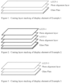
- the display element may comprise at least one at least partially ordered alignment layer.
- the alignment layer may at least partially align or order the photochromic-dichroic compound and/or the dichroic compound.
- the terms "align” or “aligned” mean to bring into suitable arrangement or position by interaction with another material, compound or structure.
- the portion of the partially aligned photochromic-dichroic compound and/or dichroic compound that is at least partially aligned by interaction with the alignment layer may be at least partially aligned such that the long-axis of the photochromic-dichroic compound in the activated state and/or dichroic compound is essentially parallel to the first general direction of the alignment layer.
- the portion of the partially aligned photochromic-dichroic compound and/or dichroic compound that is at least partially aligned by interaction with a portion of the alignment layer may be bound to or reacted with the portion of the alignment layer.
- general direction refers to the predominant arrangement or orientation of the material, compound or structure. Further, it will be appreciated by those skilled in the art that a material, compound or structure may have a general direction even though there is some variation within the arrangement of the material, compound or structure, provided that the material, compound or structure has at least one predominate arrangement.
- alignment layers include at least partial coatings comprising an at least partially ordered alignment medium, at least partially ordered polymer sheets, at least partially treated surfaces, Langmuir-Blodgett films, and combinations thereof.
- the alignment layer may comprise a coating comprising an at least partially ordered alignment medium.
- suitable alignment media include photo-orientation materials, rubbed-orientation materials, and liquid crystal materials. Methods of ordering at least a portion of the alignment medium are described herein below in detail.
- the alignment medium may be a liquid crystal material.
- Liquid crystal materials because of their structure, are generally capable of being ordered or aligned so as to take on a general direction. More specifically, because liquid crystal molecules have rod- or disc-like structures, a rigid long axis, and strong dipoles, liquid crystal molecules can be ordered or aligned by interaction with an external force or another structure such that the long axis of the molecules takes on an orientation that is generally parallel to a common axis.
- the molecules of a liquid crystal material may be aligned by using a magnetic field, an electric field, linearly polarized infrared radiation, linearly polarized ultraviolet radiation, linearly polarized visible radiation, or shear forces.
- liquid crystal molecules may be aligned with an oriented surface. That is, liquid crystal molecules may be applied to a surface that has been oriented, for example by rubbing, grooving, or photo-alignment methods, and subsequently aligned such that the long axis of each of the liquid crystal molecules takes on an orientation that is generally parallel to the general direction of orientation of the surface.
- liquid crystal materials suitable for use as alignment media include liquid crystal polymers, liquid crystal pre-polymers, liquid crystal monomers, and liquid crystal mesogens. As used herein the term "pre-polymer" means partially polymerized materials.
- Liquid crystal monomers that are suitable for use in the present invention include mono- as well as multi-functional liquid crystal monomers.
- the liquid crystal monomer may be a cross-linkable liquid crystal monomer, and may further be a photocross-linkable liquid crystal monomer.
- photocross-linkable means a material, such as a monomer, a pre-polymer or a polymer that can be cross-linked on exposure to actinic radiation.
- photocross-linkable liquid crystal monomers include those liquid crystal monomers that are cross-linkable on exposure to ultraviolet radiation and/or visible radiation, either with or without the use of polymerization initiators.
- cross-linkable liquid crystal monomers suitable for use in the present invention include liquid crystal monomers having functional groups chosen from acrylates, methacrylates, allyl, allyl ethers, alkynes, amino, anhydrides, epoxides, hydroxides, isocyanates, blocked isocyanates, siloxanes, thiocyanates, thiols, urea, vinyl, vinyl ethers and blends thereof.
- photocross-linkable liquid crystal monomers suitable for use in the coatings of the alignment layer include liquid crystal monomers having functional groups chosen from acrylates, methacrylates, alkynes, epoxides, thiols, and blends thereof.
- Liquid crystal polymers and pre-polymers that are suitable for use in the present invention include main-chain liquid crystal polymers and pre-polymers and side-chain liquid crystal polymers and pre-polymers.
- main-chain liquid crystal polymers and pre-polymers rod- or disc-like liquid crystal mesogens are primarily located within the polymer backbone.
- side-chain polymers and pre-polymers the rod- or disc-like liquid crystal mesogens primarily are located within the side chains of the polymer.
- the liquid crystal polymer or prepolymer may be cross-linkable, and further may be photocross-linkable.
- functional groups chosen from acrylates, methacrylates, allyl, allyl ethers, alkynes, amino, anhydrides, epoxides, hydroxides, isocyanates, blocked isocyanates, siloxanes, thiocyanates, thiols, urea, vinyl, vinyl ethers, and blends thereof.
- photocross-linkable liquid crystal polymers and pre-polymers that are suitable for use in the coatings of the alignment layer include those polymers and pre-polymers having functional groups chosen from acrylates, methacrylates, alkynes, epoxides, thiols, and blends thereof.
- Liquid crystals mesogens that are suitable for use in the present invention include thermotropic liquid crystal mesogens and lyotropic liquid crystal mesogens. Further, examples of liquid crystal mesogens that are suitable for use in the present invention include columatic (or rod-like) liquid crystal mesogens and discotic (or disc-like) liquid crystal mesogens.
- suitable photo-orientable polymer networks include azobenzene derivatives, cinnamic acid derivatives, coumarine derivatives, ferulic acid derivatives, and polyimides.
- the alignment layer may comprise at least one at least partial coating comprising an at least partially ordered photo-orientable polymer network chosen from azobenzene derivatives, cinnamic acid derivatives, coumarine derivatives, ferulic acid derivatives, and polyimides.
- Specific examples of cinnamic acid derivatives that may be used as an alignment medium include polyvinyl cinnamate and polyvinyl esters of paramethoxycinnamic acid.
- rubbed-orientation material means a material that can be at least partially ordered by rubbing at least a portion of a surface of the material with another suitably textured material.
- the rubbed-orientation material can be rubbed with a suitably textured cloth or a velvet brush.
- rubbed-orientation materials that are suitable for use as an alignment medium include (poly)imides, (poly)siloxanes, (poly)acrylates, and (poly)coumarines.
- the coating comprising the alignment medium may be a coating comprising a polyimide that has been rubbed with velvet or a cloth so as to at least partially order at least a portion of the surface of the polyimide.
- the at least partially ordered alignment layer may comprise an at least partially ordered polymer sheet.
- a sheet of polyvinyl alcohol can be at least partially ordered by stretching the sheet, and there after the sheet can be bonded to the at least a portion a surface of a substrate to form the alignment layer.
- the ordered polymer sheet may be made by a method that at least partially orders the polymer chains during fabrication, for example and without limitation, by extrusion.
- the at least partially ordered polymer sheet can be formed by casting or otherwise forming a sheet of a liquid crystal material and thereafter at least partially ordering the sheet for example, but exposing the sheet to at least one of a magnetic field, an electric field, or a shear force.
- the at least partially ordered polymer sheet can be made using photo-orientation methods.
- a sheet of a photo-orientation material can be formed, for example by casting, and thereafter at least partially ordered by exposure to linearly polarized ultraviolet radiation. Still other methods of forming at least partially ordered polymer sheets are described herein below.
- the alignment layer may comprise an at least partially treated surface.
- the term "treated surface” refers to at least a portion of a surface that has been physically altered to create at least one ordered region on at least a portion of the surface.
- at least partially treated surfaces include at least partially rubbed surfaces, at least partially etched surfaces, and at least partially embossed surfaces.
- the at least partially treated surfaces can be patterned, for example using a photolithographic or an interferographic process.
- at least partially treated surfaces include chemically etched surfaces, plasma etched surfaces, nanoetched surfaces (such as surfaces etched using a scanning tunneling microscope or an atomic force microscope), laser etched surfaces, and electron-beam etched surfaces.
- the alignment layer may also comprise an at least partially treated surface formed by depositing a metal salt (such as a metal oxide or metal fluoride) onto at least a portion of a surface, and thereafter etching the deposit to form an at least partially treated surface.
- a metal salt such as a metal oxide or metal fluoride
- suitable techniques for depositing a metal salt include plasma vapor deposition, chemical vapor deposition, and sputtering. Examples of etching processes are set forth above.
- Lir-Blodgett films means one or more at least partially ordered molecular films on a surface.
- a Langmuir-Blodgett film may be formed by dipping a substrate into a liquid one or more times so that it is at least partially covered by a molecular film and then removing the substrate from the liquid such that, due to the relative surface tensions of the liquid and the substrate, the molecules of the molecular film are at least partially ordered in a general direction.
- molecular film refers to monomolecular films (i.e., monolayers) as well as films comprising more than one monolayer.
- the sheet and/or coating may further comprise at least one additive that may facilitate one or more of the processing, the properties, or the performance of the film or coating.
- additives include dyes, alignment promoters, kinetic enhancing additives, photoinitiators, thermal initiators, polymerization inhibitors, solvents, light stabilizers (such as, but not limited to, ultraviolet light absorbers and light stabilizers, such as hindered amine light stabilizers (HALS)), heat stabilizers, mold release agents, rheology control agents, leveling agents (such as, but not limited to, surfactants), free radical scavengers, self-assembling materials, gelators, and adhesion promoters (such as hexanediol diacrylate and coupling agents).
- HALS hindered amine light stabilizers
- leveling agents such as, but not limited to, surfactants
- free radical scavengers such as hexanediol diacrylate and coupling agents.
- the sheet or coating may comprise at least one conventional photochromic compound.
- conventional photochromic compound includes both thermally reversible and non-thermally reversible (or photo-reversible) photochromic compounds, and excludes photochromic-dichroic compounds.
- the display elements according to the present invention may optionally further comprise at least one additional coating chosen from conventional photochromic coatings, antireflective coatings, linearly polarizing coatings, circularly polarizing coatings, elliptically polarizing coatings, transitional coatings, primer coatings, and protective coatings such as antifogging coatings, oxygen barrier coatings, and ultraviolet light absorbing coatings connected to at least a portion of the substrate.
- additional coating means a coating that aids in creating a gradient in properties between two coatings.
- a transitional coating may aid in creating a gradient in hardness between a relatively hard coating and a relatively soft coating.
- transitional coatings include radiation-cured acrylate-based thin films.
- the display elements according to the present invention may further comprise at least one coating comprising an at least partially ordered alignment transfer material interposed between the alignment layer and the photochromic-dichroic compound and/or the dichroic compound (or film or coating comprising the same). Still further, the display elements may comprise a plurality of coatings comprising an alignment transfer interposed between the alignment layer and the photochromic-dichroic compound.
- the display element may comprise at least one alignment layer comprising a coating comprising an at least partially ordered alignment medium connected to the substrate, and a coating comprising an at least partially ordered alignment transfer material connected to the alignment layer.
- the photochromic-dichroic compound and/or dichroic compound may be at least partially aligned by interaction with the alignment transfer material.
- alignment transfer materials that are suitable for use in the display element include, without limitation, those liquid crystal materials described above in connection with the alignment media disclosed herein.
- the alignment layer may have a thickness that varies widely depending upon the final application and/or the processing equipment employed, such as, for example, from at least 0.5 nanometers to 10,000 nanometers, such as 0.5 to 1,000 nanometers, such as 2 to 500 nanometers, such as 100 to 500 nanometers.
- the sheet or coating comprising the alignment transfer material may have a thickness that varies widely depending upon the final application and/or the processing equipment employed, such as, for example, from 0.5 microns to 1000 microns, such as 1 to 25 microns, such as 5 to 20 microns.
- the sheet or coating comprising the photochromic-dichroic compound and/or the dichroic compound may have a thickness that varies widely depending upon the final application and/or the processing equipment employed, such as, for example, from 0.5 microns to 1,000 microns, such as 1 to 25 microns, such as 5 to 20 microns.
- the display elements of the present invention may further comprise a birefringent layer.
- the birefringent layer is operable to circularly or elliptically polarize transmitted radiation.
- the birefringent layer comprises a quarter-wave plate.
- the birefringent layer also called a compensation plate or layer or a retardation plate or layer, may be composed of one sheet or may be a multiple layer structure of two or more.
- the birefringent layer may comprise a layer having a first ordered region having a first general direction, and at least one second ordered region adjacent the first ordered region having a second general direction that is the same or different from the first general direction so as to form a desired pattern in the layer.
- the material used to prepare the birefringent layer is not particularly limited, and may be any birefringent material known in the art.
- a polymer film, a liquid crystal film, self-assembling materials, or a film in which a liquid crystal material is aligned may be used.
- Examples of particular birefringent layers include those described in U.S. Pat. No. 6,864,932 at column 3, line 60 to column 4, line 64; U.S. Pat No. 5,550,661 at column 4, line 30 to column 7, line 2; U.S. Pat. No. 5,948,487 at column 7, line 1 to column 10, line 10.
- birefringent films examples include film Model No. NRF-140, a positively birefringent, uniaxial film available from Nitto Corporation, Japan, or Nitto Denko America, Inc., New Brunswick, N.J. Also suitable are OPTIGRAFIX circular polarizer films, available from GRAFIX Plastics, a division of GRAFIX, Inc., Cleveland, Ohio.
- Specific polymeric sheets used to prepare the birefringent layer may comprise polyacrylates, polymethacrylates, poly(C 1 -C 12 ) alkyl methacrylates, polyoxy(alkylene methacrylates), poly (alkoxylated phenol methacrylates), cellulose acetate, cellulose triacetate, cellulose acetate propionate, cellulose acetate butyrate, poly(vinyl acetate), poly(vinyl alcohol), poly(vinyl chloride), poly(vinylidene chloride), poly(vinylpyrrolidone), poly((meth)acrylamide), poly(dimethyl acrylamide), poly(hydroxyethyl methacrylate), poly((meth)acrylic acid), thermoplastic polycarbonates, polyesters, polyurethanes, polythiourethanes, poly(ethylene terephthalate), polystyrene, poly(alpha methylstyrene), copoly(styrene-methylmethacrylate), copoly
- the birefringent layer may be incorporated into the display element in such a way that a slow axis direction (direction where a refractive index is largest in a plane) of the birefringent layer is oriented with respect to an alignment direction of the polarizer to yield the desired resultant polarization; i.e., circular or elliptical.
- a quarter-wave plate would be oriented at an angle of 45°+/-5° with respect to an alignment direction of the polarization produced by the photochromic-dichroic compound and/or dichroic compound, such as 45°+/-3°.
- the resultant polarization of the display element may be determined by setting the thickness of the birefringent layer.
- the thickness of the birefringent layer is such that the emerging refracted rays of light are out of phase by one-quarter wavelength.
- the method of making the display element may comprise forming a coating comprising an at least partially aligned photochromic-dichroic compound and/or dichroic compound on a substrate or film.
- the method of making the display element may comprise forming a first coating comprising an at least partially aligned photochromic-dichroic compound, and forming a second coating comprising an at least partially aligned dichroic compound on the substrate or film.
- the method of making the display element may comprise forming a first coating comprising an at least partially aligned dichroic compound, and forming a second coating comprising an at least partially aligned photochromic-dichroic compound on the substrate or film.
- forming the coating comprising the photochromic-dichroic compound and/or dichroic compound may comprise applying the photochromic-dichroic compound and/or dichroic compound and an anisotropic material to the substrate or film, at least partially ordering the anisotropic material, and at least partially aligning the photochromic-dichroic compound and/or dichroic compound with the anisotropic material.
- Methods of applying the photochromic-dichroic compound and/or dichroic compound and the anisotropic material to the substrate or film include, but are not limited to, spin coating, spray coating, spray and spin coating, curtain coating, flow coating, dip coating, injection molding, casting, roll coating, wire coating, and overmolding.
- applying the photochromic-dichroic compound and the anisotropic material to the substrate may comprise forming a coating of the anisotropic material on a mold, which may be treated with a release material. Thereafter, the anisotropic material may be at least partially ordered (as discussed in more detail below) and at least partially set Thereafter, the substrate can be formed over the coating (i.e., overmolding), for example, by casting the substrate forming material in the mold. The substrate forming material can then be at least partially set to form the substrate. Subsequently, the substrate and the coating of the anisotropic material can be released from the mold.
- the photochromic-dichroic compound can be applied to the mold with the anisotropic material, or it can be imbibed into the anisotropic material after the anisotropic material has been applied to the mold, after the anisotropic material has been at least partially ordered, or after the substrate with the coating of the ordered anisotropic material has been released from the mold.
- forming the coating comprising the photochromic-dichroic compound and/or dichroic compound may comprise applying an anisotropic material to the substrate or film, imbibing a photochromic-dichroic compound and/or a dichroic compound into the anisotropic material, at least partially ordering the anisotropic material, and at least partially aligning the photochromic-dichroic compound and/or dichroic compound with the anisotropic material.
- Methods of ordering the anisotropic material include exposing the anisotropic material to at least one of a magnetic field, an electric field, linearly polarized ultraviolet radiation, linearly polarized infrared radiation, linearly polarized visible radiation, and a shear force. Further, the anisotropic material may be at least partially ordered by aligning the anisotropic material with another material or structure. For example, although not limiting herein, the anisotropic material can be at least partially ordered by aligning the anisotropic material with an alignment layer, such as, but not limited to, those alignment layers previously discussed.
- the anisotropic material by ordering at least a portion of the anisotropic material, it is possible to at least partially align the photochromic-dichroic compound and/or dichroic compound contained within or otherwise connected to the anisotropic material. Further, applying the photochromic-dichroic compound and/or dichroic compound and the anisotropic material to the substrate can occur at essentially the same time as, prior to, or after ordering the anisotropic material and/or aligning the photochromic-dichroic compound and/or the dichroic compound.
- Applying the coating materials may comprise spin coating a solution or mixture of the photochromic-dichroic compound and/or dichroic compound and anisotropic material (optionally in a solvent or carrier) onto the substrate.
- the anisotropic material may be at least partially ordered, for example, by exposing the anisotropic material to a magnetic field, an electric field, linearly polarized ultraviolet radiation, linearly polarized infrared radiation, linearly polarized visible radiation, or a shear force. Further the anisotropic material may be at least partially ordered by aligning the anisotropic material with another material or structure, for example, an alignment layer.
- a solution or mixture (optionally in a solvent or carrier) of the photochromic-dichroic compound and/or dichroic compound and the anisotropic material can be applied to an ordered polymeric sheet to form a coating. Thereafter, the anisotropic material may be allowed to align with the polymeric sheet.
- the polymeric sheet may be subsequently applied to a substrate by, for example, but not limited to, laminating or bonding.
- the coating may be transferred from the polymeric sheet to the substrate by methods known in the art, such as, but not limited to hot stamping.
- applying the photochromic-dichroic compound and/or dichroic compound and anisotropic material to the substrate may comprise applying a phase-separating polymer system comprising a matrix phase-forming material comprising a liquid crystal material and a guest phase-forming material comprising the anisotropic material and photochromic-dichroic compound and/or dichroic compound.
- the liquid crystal material of the matrix phase and the anisotropic material of the guest phase may be at least partially ordered, such that the photochromic-dichroic compound and/or dichroic compound is aligned with the anisotropic material of the guest phase.
- Methods of at least partially ordering the matrix phase-forming material and the guest phase-forming material of the phase-separating polymer system include exposing the coating comprising the phase-separating polymer system to at least one of: a magnetic field, an electric field, linearly polarized infrared radiation, linearly polarized ultraviolet radiation, linearly polarized visible radiation, and a shear force. Further, at least partially ordering the matrix phase-forming material and the guest phase-forming material may comprise at least partially aligning the portions with an alignment layer.
- the guest phase-forming material may be separated from the matrix phase-forming material by polymerization induced phase separation and/or solvent induced phase separation.
- polymerization induced phase separation and/or solvent induced phase separation.
- this language is intended to cover any separation between the two phase-forming materials. That is, this language is intended to cover separation of the guest phase-forming material from the matrix phase-forming material and separation of the matrix phase-forming material from the guest phase-forming material, as well as, simultaneous separation of both phase-forming materials and any combination thereof.
- the matrix phase-forming material may comprise a liquid crystal material chosen from liquid crystal monomers, liquid crystal pre-polymers, and liquid crystal polymers.
- the guest phase-forming material may comprise a liquid crystal material chosen from liquid crystal mesogens, liquid crystal monomers, and liquid crystal polymers and pre-polymers.
- forming the coating comprising the photochromic-dichroic compound and/or dichroic compound may comprise applying an anisotropic material to the substrate or film, imbibing the photochromic-dichroic compound and/or dichroic compound into the anisotropic material, at least partially ordering the anisotropic material, and at least partially aligning the photochromic-dichroic compound and/or dichroic compound with the anisotropic material. Further, at least partially ordering the anisotropic material may occur before imbibing the photochromic-dichroic compound and/or dichroic compound thereinto.
- the photochromic-dichroic compound and/or dichroic compound may be imbibed into the anisotropic material, for example, by applying a solution or mixture of the photochromic-dichroic compound and/or dichroic compound in a carrier to a portion of the anisotropic material and allowing the photochromic-dichroic compound and/or dichroic compound to diffuse into the anisotropic material, either with or without heating.
- the anisotropic material may be part of a phase-separated polymer coating as described above.
- the method of making a display element may also comprise imparting at least one alignment layer to a substrate, subsequently forming a coating comprising an at least partially aligned photochromic-dichroic compound on the alignment layer, impart at least one alignment layer onto the formed coating, and subsequently forming a coating comprising an at least partially aligned dichroic compound on the alignment layer.
- Imparting the alignment layer to the substrate may comprise at least one of forming a coating comprising an at least partially ordered alignment medium on the substrate, applying an at least partially ordered polymer sheet to the substrate, treating the substrate, and forming a Langmuir-Blodgett film on the substrate.
- imparting the alignment layer may comprise forming a coating of an at least partially ordered alignment medium
- the alignment medium may be at least partially set.
- setting the alignment medium may occur at essentially the same time as aligning the alignment medium or it can occur after aligning the alignment medium.
- setting the alignment medium may comprise at least partially curing the medium by exposing it to infrared, ultraviolet, gamma, microwave or electron radiation so as to initiate the polymerization reaction of the polymerizable components or cross-linking with or without a catalyst or initiator. If desired or required, this may be followed by a heating step.
- a coating comprising an at least partially aligned photochromic-dichroic compound and/or dichroic compound may be formed on the alignment layer.
- the polymerizable composition may be an isotropic material or an anisotropic material, provided that the coating comprising the photochromic-dichroic compound and/or dichroic compound is, on the whole, anisotropic.
- forming a sheet may comprise applying a phase-separating polymer system comprising a matrix phase-forming material comprising a liquid crystal material, a guest phase-forming material comprising a liquid crystal material, and at least one photochromic-dichroic compound and/or dichroic compound onto a substrate. Thereafter, the matrix phase-forming material and the guest phase-forming material may be at least partially ordered, and the photochromic-dichroic compound and/or dichroic compound may be at least partially aligned with the guest phase-forming material.
- the guest phase-forming material may be separated from the matrix phase-forming material by polymerization induced phase-separation and/or solvent induced phase-separation, and the phase-separated polymer coating can be removed from the substrate to form the sheet
- phase-separating polymer system may be applied on the substrate, ordered and aligned as discussed above, and thereafter removed from the substrate to form a phase-separated polymer sheet Subsequently, a photochromic-dichroic compound and/or dichroic compound may be imbibed into the sheet Alternatively, or additionally, a photochromic-dichroic compound and/or dichroic compound may be imbibed into the coating prior to removing the coating from the substrate to form the sheet
- forming the sheet may comprise forming an at least partially ordered liquid crystal polymer sheet and imbibing liquid crystal mesogens and a photochromic-dichroic compound and/or dichroic compound into the liquid crystal polymer sheet
- a sheet comprising a liquid crystal polymer may be formed and at least partially ordered by a method of forming a polymer sheet that at least partially order the liquid crystal polymer during formation, for example by extrusion.
- a liquid crystal polymer can be cast onto a substrate and at least partially ordered by one of the methods of ordering liquid crystal materials set forth above.
- the liquid crystal material may be exposed to a magnetic or an electric field.
- the liquid crystal polymer may be at least partially set and removed from the substrate to form a sheet comprising an at least partially ordered liquid crystal polymer matrix. Still further, a liquid crystal polymer sheet may be cast, at least partially set, and subsequently stretched to form a sheet comprising an at least partially ordered liquid crystal polymer.
- a liquid crystal mesogen and a photochromic-dichroic compound and/or dichroic compound may be imbibed into the liquid crystal polymer matrix.
- the liquid crystal mesogen and the photochromic-dichroic compound and/or dichroic compound may be imbibed into the liquid crystal polymer by applying a solution or mixture of the liquid crystal mesogen and the photochromic-dichroic compound and/or dichroic compound in a carrier to the liquid crystal polymer and, thereafter, allowing the liquid crystal mesogen and the photochromic-dichroic compound and/or dichroic compound to diffuse into the liquid crystal polymer sheet, either with or without heating.
- the sheet comprising the liquid crystal polymer may be immersed into a solution or mixture of the liquid crystal mesogen and the photochromic-dichroic compound and/or dichroic compound in a carrier and the liquid crystal mesogen and the photochromic-dichroic compound and/or dichroic compound may be imbibed into the liquid crystal polymer sheet by diffusion, either with or without heating.
- forming the sheet may comprise forming a liquid crystal polymer sheet, imbibing the liquid crystal polymer sheet with a liquid crystal mesogen and a photochromic-dichroic compound and/or dichroic compound (for example as discussed above), and thereafter at least partially ordering the liquid crystal polymer, the liquid crystal mesogen, and the photochromic-dichroic compound and/or dichroic compound distributed therein.
- the liquid crystal polymer sheet, the liquid crystal mesogen, and the photochromic-dichroic compound and/or dichroic compound distributed therein can be at least partially ordered by stretching the liquid crystal polymer sheet.
- the liquid crystal polymer sheet may be formed using conventional polymer processing techniques, such as, but not limited to, extrusion and casting.
- a photo-oriented polymer sheet comprising a coating of an anisotropic material and a photochromic-dichroic compound and/or dichroic compound may be applied to the substrate.
- the photo-oriented polymer sheet may be formed by applying a layer of a photo-orientable polymer network on a release layer and subsequently ordering and at least partially curing the photo-orientable polymer network; forming a coating of an anisotropic material and a photochromic-dichroic compound and/or dichroic compound on the layer comprising the photo-orientable polymer network, at least partially aligning the anisotropic material and the photochromic-dichroic compound and/or dichroic compound with the photo-orientable polymer network, and curing the anisotropic material.
- the release layer may then be removed and the layer of the photo-orientable polymer network comprising the coating of the anisotropic material and the photochromic-dichroic compound from the release layer to form the ordered polymeric sheet
- connecting the polymeric sheet comprising the photochromic-dichroic compound and/or dichroic compound to the substrate may comprise, for example, at least one of laminating, fusing, in-mold casting, and adhesively bonding the polymeric sheet to the substrate.
- the in-mold casting includes a variety of casting techniques, such as but not limited to: overmolding, wherein the sheet is placed in a mold and the substrate is formed (for example by casting) over at least a portion of the sheet; and injection molding, wherein the substrate is formed around the sheet.
- the display element may optionally comprise a birefringent layer.
- the birefringent layer may be applied by, for example, laminating or adhesive bonding.
- the birefringent layer may be applied by methods known in the art, such as hot stamping.
- Suitable adhesives for connecting the birefringent layer include those disclosed in U.S. Pat. No. 6,864,932 at column 4, line 65 through column 60.
- the present invention is directed to display elements and devices.
- display means the visible representation of information in words, numbers, symbols, designs or drawings. Examples of display devices include screens and monitors.
- the display device of the present invention includes the display element described above.
- the display device may comprise an organic light emitting diode (OLED), a light emitting diode (LED), a liquid crystal display (LCD), a plasma display panel (PDP), an electroluminescent display (ELD), or a cathode ray tube (CRT).
- OLED organic light emitting diode
- LED light emitting diode
- LCD liquid crystal display
- PDP plasma display panel
- ELD electroluminescent display
- CRT cathode ray tube
- the display device may comprise a light-emitting source, such as a light-emitting layer, and the display element of the present invention.
- the display device may optionally further comprise a reflective backing layer that assists in directing the radiation generated from the light-emitting source out of the display device through the display element.
- the display element comprises at least one layer comprising the photochromic-dichroic compound, the dichroic compound, or combinations thereof.
- the display device may further comprise a birefringent layer.
- the birefringent layer may comprise a quarter-wave plate (also known as a quarter-wave retarder).
- the light generated by the light-emitting source may be referred to as display light
- the dichroic compound and/or photochromic-dichroic compound of the display element will linearly polarize and absorb a portion of the display light as it passes through the display element.
- the display element will transmit radiation at different percentages (%T) in the first state and second state of the display element.
- ambient or environmental light may be transmitted into the display device through the display element.
- the display element As ambient or environmental light passes through the display element, at least a portion of the light is linearly polarized and/or absorbed by the dichroic compound and/or photochromic/dichroic compound.
- the ambient or environmental light may pass through a birefringent layer such as a quarter wave plate that transforms the linearly polarized light into circularly polarized light.
- the axis of the quarter-wave plate may be oriented at 45 degrees with respect to the axis of the linear polarizing layer(s) that comprise the photochromic-dichroic compound and/or dichroic compound.
- the ambient or environmental linearly polarized light passes through the quarter-wave plate, it is converted to circularly polarized light.
- At least a portion of the circularly polarized light may pass through the light-emitting source and may be reflected by the reflective backing layer wherein the propagation of the circularly polarized light is in the opposite direction (e.g., from right-hand circularly polarized to left-hand circularly polarized light).
- the reflected circularly polarized light may then pass back through the light-emitting source into the quarter wave plate.
- the linear polarizing layer(s) that comprises the photochromic-dichroic compound and/or dichroic compound effectively absorbs or blocks the returning reflected light from being transmitted back through the display element
- the resultant reflected light is thus reduced in intensity compared to the initial intensity of the ambient or environmental light that passed through the display element of the present invention.
- Ambient or environmental light is directed towards the display device from many different incident angles, and not every angle of ambient or environmental light will pass through the display element in this manner.
- the transmission of reflected light through the display element is reduced compared to the transmission of the light generated from the light-emitting source that only passes through the display element once. This results in improved readability of the display device in bright or sunny conditions.
- the transmission percentage of the display element varies. For example, in the first state most, if not all, of the photochromic-dichroic compound is un-activated, and does not linearly polarize or absorb radiation. Accordingly, any linearly polarization or absorption of radiation is provided by the dichroic compound, and the display element transmits a larger percentage of radiation. As the photochromic-dichroic compound is activated, the photochromic-dichroic compound linearly polarizes and absorbs radiation. Accordingly, the linear polarization and absorption of radiation is enhanced, and the display element transmits a reduced percentage of radiation compared to the first state. Appropriate transmission percentages for the first and second states of the display element are discussed above.
- each numerical parameter should at least be construed in light of the number of reported significant digits and by applying ordinary rounding techniques.
- a closed or open-ended numerical range is described herein, all numbers, values, amounts, percentages, subranges and fractions within or encompassed by the numerical range are to be considered as being specifically included in and belonging to the original disclosure of this application as if these numbers, values, amounts, percentages, subranges and fractions had been explicitly written out in their entirety.
- the terms “on,” “onto,” “applied on,” “applied onto,” “formed on,” “deposited on,” “deposited onto,” mean formed, overlaid, deposited, or provided on but not necessarily in contact with the surface.
- coating "deposited onto” a substrate does not preclude the presence of one or more other intervening coating layers of the same or different composition located between the coating and the substrate.
- liquid crystal monomer (“LCM”) compositions were prepared:
- LCM-1 was 1-(6-(8-(4-(4-(4-(8-acryloyloxyhexyl)oxy)benzoyloxy)phenyloxycarbonyl)phenoxy)octyloxy)-6-oxohexyloxy)-6-oxohexyloxy)-6-oxohexyloxy)-6-oxohexyloxy)-6-oxohexyloxy)-6-oxohexyloxy)-6-oxohexyloxy)-6-oxohexan-1-ol which was prepared according to the procedures described in Example 17 of U.S. Pat. No. 7910019 .
- LCM-2 was commercially available RM257 reported to be 4-(3-acryloyloxypropyloxy)-benzoic acid 2-methyl-1,4-phenylene ester, available from EMD Chemicals, Inc., having the molecular formula of C 33 H 32 O 10 .
- LCM-4 was 1-(6-(6-(6-(6-(6-(6-(6-(6-(8-(4-(4-(4-hexyloxybenzoyloxy)phenoxycarbonyl)-phenoxy)octyloxy)-6-oxohexyloxy)-6-oxohexyloxy)-6-oxohexyloxy)-6-oxohexyloxy)-6-oxohexyloxy)-6-oxohexyloxy)-6-oxohexyloxy)-2-methylprop-2-en-1-one prepared according to the procedures of U.S. Pat. No. 7910019 .
- LCM-5 was commercially available RM105 available from EMD Chemicals, Inc and is reported to have the molecular formula of C 23 H 26 O 6 .
- a photochromic-dichroic grey coloring formulation referred to herein as Grey-1
- Grey-1 was prepared by combining the photochromic-dichroic ("PC") dyes listed in Table A below.
- PC photochromic-dichroic
- Table A Photochromic Dyes in Grey-1 Coloring Formulation Dye Description Amount (weight percent based on die total weight of the coloring formulation) PC-A Indenonaphthopyran that demonstrates a yellow color upon activation (as described in Example 25 of U.S. Pat. No. 8,518,546 ) 23.0 PC-B Indenonaphthopyran that demonstrates a blue-green color upon activation (as described in Example 33 of U.S. Pat. No.
- LCCF-1 was prepared as follows: To a suitable flask containing a mixture of anisole (3.99 g) and BYK-322 additive 0.004 g, reported to be an aralkyl modified poly-methyl-alkyl-siloxane available from BYK Chemie, USA), was added LCM-1 (1.08 g), LCM-2 (2.4 g), LCM-3 (1.08 g), LCM-4 (1.44 g), Grey-1 (0.72 g), 4-methoxyphenol (0.006 g) and IRGACURE ® 819 (0.09 g, a photoinitiator available from Ciba-Geigy Corporation).
- LCCF-2 was prepared as follows: To a suitable flask containing a mixture of anisole (3.99 g) and BYK-322 additive 0.004 g, reported to be an aralkyl modified poly-methyl-alkyl-siloxane available from BYK Chemie, USA), was added LCM-2 (3.0 g), LCM-5 (3.0 g), Dichroic Dye Blue AB2 Batch 3 from Nematel GmbH & Co. KG (0.06 g), Dichroic Dye Orange AZ01 Batch 1 from Nematel GmbH & Co.
- LCCF-3 was prepared as follows: To a suitable flask containing a mixture of anisole (3.99 g) and BYK-322 additive 0.004 g, reported to be an aralkyl modified poly-methyl-alkyl-siloxane available from BYK Chemie, USA), was added LCM-1 (1.08 g), LCM-2 (2.4 g), LCM-3 (1.08 g), LCM-4 (1.44 g), Grey-1 (0.72 g), Dichroic Dye Blue AB2 Batch 3 from Nematel GmbH & Co. KG (0.012 g), Dichroic Dye Orange AZ01 Batch 1 from Nematel GmbH & Co.
- a solution of a photo alignment material, poly[(E)-2-methoxy-4-(3-methoxy-3-oxoprop-1-enyl)phenyl 4-(6-(methacryloyloxy)hexyloxy)benzoate] was prepared by adding 6 weight percent of the photo alignment material to cyclopentanone, based on the total weight of the solution.
- Corning 2947-75x50mm glass plate microslides were used as the substrate.
- the plates had dimensions of 75x50mm, with a thickness of 0.96 to 1.06mm.
- Each substrate was cleaned by wiping with a tissue soaked with Windex ® and dried with a stream of air.
- Each substrate was corona treated by passing on a conveyor belt in Tantec EST Systems Serial No. 020270 Power Generator HV 2000 series corona treatment equipment with a high voltage transformer.
- the substrates were exposed to corona generated by 53.99 KV, 500 Watts while traveling on a conveyor at a belt speed 3 ft/min.
- the photo alignment coating solution prepared in Example B was applied to the test substrates by spin-coating on a portion of the surface of the test substrate by dispensing approximately 1.0 mL of the solution and spinning die substrates at 800 revolutions per minute (rpm) for 3 seconds, followed by 1,000 rpm for 7 seconds, followed by 2500 rpm for 4 seconds.
- a spin processor from Laurell Technologies Corp. (WS-400B-6NPP/LITE) was used for spin coating. Afterwards, the coated substrates were placed in an oven maintained at 120° C. for 30 minutes. The coated substrates were cooled to about 26° C.
- the dried photo alignment layer on each of the substrates was at least partially ordered by exposure to linearly polarized ultraviolet radiation using a DYMAX ® UVC-6 UV/conveyor system by DYMAX ® Corp. having a 400-Watt power supply.
- the light source was oriented such that the radiation was linearly polarized in a plane perpendicular to the surface of the substrate.
- the amount of ultraviolet radiation that each photo alignment layer was exposed to was measured using a UV Power Puck TM High energy radiometer from EIT Inc (Serial No.
- UVA 0.126 W/cm 2 and 5.962 J/cm 2 UVB 0.017 W/cm 2 and 0.078 J/cm 2 ; UVC 0 W/cm 2 and 0 J/cm 2 ; and UVV 0.046 W/cm 2 and 2.150 J/cm 2 .
- the substrates were cooled to about 26° C. and kept covered.
- LCCF Liquid Crystal Coating Formulations
- the substrates were cured under two ultraviolet lamps in the UV Curing Oven Machine designed and built by Belcan Engineering in nitrogen atmosphere while running on a conveyor belt at 2 ft/min speed at peak intensity of 0.445 Watts/cm 2 of UVA and 0.179 Watts/cm 2 of UW and UV dosage of 2.753 Joules/cm 2 of UVA and 1.191 Joules/cm 2 of UW.
- the cured layers were exposed to corona generated by 53.00 KV, 500 Watts while traveling on a conveyor at a belt speed 3 ft/min using the corona treatment equipment described above.
- Example 1 The control sample, Example 1, was coated with the photoalignment layer of Example B and the LCCF-1 coating of Example A according to the procedure of Example C.
- the display element of Example 1 contained photochromic-dichroic dye but no fixed-tint dichroic dyes.
- the layer stacking configuration is shown in Figure 1 .
- Example 2 was coated with has multilayer stack of photo alignment coating / LCCF-2 coating / photo alignment coating / LCCF-1 coatings of Examples A and B according to the procedure of Example C.
- the display element of Example 2 contained both photochromic-dichroic dye and dichroic dyes.
- the layer stacking configuration is shown in Figure 2 .
- Example 3 was coated with the photoalignment layer of Example B and the LCCF-3 coating of Example A according to the procedure of Example C.
- the display element of Example 3 contained both photochromic-dichroic dye and dichroic dyes.
- the layer stacking configuration is shown in Figure 3 .
- the activating light source (a Newport/Oriel Model 67005 300-Watt Xenon arc lamp housing, 69911 power supply and 68945 digital exposure controller fitted with a Uniblitz VS25 (with VMM-D4 shutter driver) high-speed computer controlled shutter that momentarily closed during data collection so that stray light would not interfere with the data collection process, a Schott 3 mm KG-2 band-pass filter, which removed short wavelength radiation, neutral density filter(s) for intensity attenuation and a condensing lens for beam collimation) was directed at a 30° to 35° angle of incidence to the surface of the sample side.
- the activating light source a Newport/Oriel Model 67005 300-Watt Xenon arc lamp housing, 69911 power supply and 68945 digital exposure controller fitted with a Uniblitz VS25 (with VMM-D4 shutter driver) high-speed computer controlled shutter that momentarily closed during data collection so that stray light would not interfere with the data collection process
- a broadband light source for monitoring response measurements was positioned in a perpendicular manner to a surface of the display element. Increased signal of shorter visible wavelengths was obtained by collecting and combining separately filtered light from a 100-Watt tungsten halogen lamp (controlled by a Lambda. UP60-14 constant voltage power supply) with a split-end, bifurcated fiber optical cable. Light from one side of the tungsten halogen lamp was filtered with a Schott KG1 filter to absorb heat and a Hoya B-440 filter to allow passage of the shorter wavelengths. The other side of the light was either filtered with a Schott KG1 filter or unfiltered.
- the light was collected by focusing light from each side of the lamp onto a separate end of the split-end, bifurcated fiber optic cable, and subsequently combined into one light source emerging from the single end of the cable.
- a 4" light pipe was attached to the single end of the cable to insure proper mixing.
- Polarization of the light source was achieved by passing the light from the single end of the cable through a Moxtek, Proflux Polarizer held in a computer driven, motorized rotation stage (Model M-061-PD or M-660.55 from Polytech, PI).
- the monitoring beam was set so that the one polarization plane (0°) was perpendicular to the plane of the optical bench table and the second polarization plane (90°) was parallel to the plane of the optical bench table.
- the display elements Prior to UV activation the display elements were aligned as follows. Electrical dark, reference and dark spectra were collected at both 0 and 90-degree polarization directions. Alignment of the polarization samples was accomplished by activating the sample for 15 minutes, then rotating the sample relative to the Moxtek analyzer polarizer until a maximum absorbance at 590 nm is achieved. At this position, the sample is aligned 90 degrees to the analyzer polarizer to +/- 0.25 degrees.
- the 0/90-degree absorption spectra were collected for 120 seconds at 5 second intervals, and then the Xe arc lamp shutter is closed and the sample is allowed to fade while the Moxtek polarizer continues to rotate and collect the absorption spectra at 0 and 90 degrees as a function of time.
- the display element was exposed to 6.7 W/m2 of UVA from the activating light source for 15 minutes to activate the photochromic-dichroic dyes.
- An International Light Research Spectrorradiometer (Model ILT950) with a detector system (Model SED033 detector, B Filter, and diffuser) was used to verify exposure at the beginning of each day.
- Light from the monitoring source that was polarized to the 0° polarization plane was then passed through the coated sample and focused on a 1" integrating sphere, which was connected to an Ocean Optics 2000 spectrophotometer using a single function fiber optic cable.
- the spectral information, after passing through the sample, was collected using Ocean Optics SpectraSuite and PPG propriety software.
- Absorption spectra were obtained and analyzed for each display element using the Igor Pro software (available from WaveMetrics). The change in the absorbance in each polarization direction for each display element was calculated by subtracting out the 0-time (i.e., unactivated) absorption measurement for the display element at each wavelength tested. Photopic response measurements were collected since multiple photochromic-dichroic compounds were used in the display elements. Average absorbance values were obtained in the photopic region of the activation profile where the photochromic response was saturated or nearly saturated (i.e., the regions where the measured absorbance did not increase or did not increase significantly over time) for each display element by averaging absorbance at each time interval in this region.
- the average absorbance values in a predetermined range of wavelengths corresponding ⁇ max-vis+/-5 nm were extracted for the 0° and 90° polarizations, and the absorption ratio for each wavelength in this range was calculated by dividing the larger average absorbance by the small average absorbance. For each wavelength extracted, 5 to 100 data points were averaged. The average absorption ratio for the photochromic-dichroic dyes was then calculated by averaging these individual absorption ratios. The average absorption ratio for the sample was then calculated by averaging these individual absorption ratios.
- T1 ⁇ 2 the First Fade Half Life
- %T values were calculated based on CIE Y transmission for a grey/brown lens.
- the clear to circular polarization studies were conducted in the same manner as the clear to linear studies except for the modifications described below.
- the Moxtek polarizer was moved on the PI rotation stage to the side opposite of the film assembly. In order to do circular polarization measurements, the circular polarizers need to face each other such that the quarter wave plates are facing each other.
- a known Melles Griot (MG) polarizer was placed in position prior to the cell assembly, oriented at 0 degrees for maximum transmission of the laser light (Coherent Ultra-low noise laser diode module -635 nm). The Moxtek polarizer was then rotated on the stage to achieve a null position.
- MG Melles Griot
- a quarter wave plate (from Melles Griot) was added to the optical path just before the Moxtek polarizer.
- the Quarter wave plate (mounted on a goniometer from Opto-Sigma which had a rotation center point 76 mm away from the top plate: this assembly was mounted on a 1.5-inch damped rod from Melles Griot) was rotated to achieve a null signal of the laser. This ensured that either the fast or slow axes of the quarter wave plate was aligned with the Moxtek polarizers transmission direction.
- the Moxtek polarizer was rotated 45 degrees and the MG polarizer was removed.
- the Moxtek polarizer now bisected the fast and slow axes of the MG quarter wave plate and produced either left hand or right hand circularly polarized light. Electrical dark, reference and dark reference spectra were collected for both left hand and right hand circularly polarized light by rotating the Moxtek Polarizer +/-90 degrees (alternatively bisecting the fast and slow axes of the MG quarter wave plate from fast to slow and then slow to fast).
- the sample was inserted into the temperature-controlled air cell.
- the Moxtek polarizer was rotated 45 degrees to be horizontal and the MG polarizer (at 0 degrees) was placed in the beam path to produce a crossed polarizer configuration.
- the display element was placed in the beam path and the laser was directed through the crossed polarizers and sample. Alignment of the polarization samples was accomplished by activating the sample for 15 minutes, then rotating the sample relative to the Moxtek analyzer polarizer until a maximum absorbance at 590 nm is achieved. At this position, the sample is aligned 90 degrees to the analyzer polarizer to +/- 0.25 degrees.
- the 0/90-degree absorption spectra were collected for 120 seconds at 5 second intervals, and then the Xe arc lamp shutter is closed and the sample is allowed to fade while the Moxtek polarizer continues to rotate and collect the absorption spectra at 0 and 90 degrees as a function of time.
- Example 2 the poor-quality quarter wave-plate of the sample (due to refractive index dispersion) required that the data be analyzed manually so that the correct "crossed polarization" spectrum was used. From the raw data tables that are generated by the optical bench, the bleached optical densities at the angle (to +/- 2.5 degrees) where the maximum darkness in crossed polarization was found were used to back calculate the bleached CIE Y transmission (%T) and the fully activated transmission. This was done because there is some level of angular dependence between crossed circular polarizers that is due to the poor quality of the quarter wave plates across 380 to 780 nm (they are designed for 560 nm).
- the data acquisition was done as before (120 second delay, 15 minutes activation at 5 second interval data collection, 30 minutes fade or to 2nd half-life at 3 second intervals.
- the Moxtek polarizer was rotated +/-90 degrees throughout the data collection. Since the transmission axis of the Moxtek polarizer bisected the quarter wave plate (MG), then the rotation of the Moxtek polarizer went from bisecting the fast-slow axes to bisecting the slow-fast axes, which created right hand circular polarized light in one orientation and left-hand circular polarized light in the other orientation.
Landscapes
- Physics & Mathematics (AREA)
- General Physics & Mathematics (AREA)
- Optics & Photonics (AREA)
- Nonlinear Science (AREA)
- Chemical & Material Sciences (AREA)
- Engineering & Computer Science (AREA)
- Materials Engineering (AREA)
- Organic Chemistry (AREA)
- Mathematical Physics (AREA)
- Crystallography & Structural Chemistry (AREA)
- General Chemical & Material Sciences (AREA)
- Chemical Kinetics & Catalysis (AREA)
- Life Sciences & Earth Sciences (AREA)
- Geochemistry & Mineralogy (AREA)
- Spectroscopy & Molecular Physics (AREA)
- Toxicology (AREA)
- Health & Medical Sciences (AREA)
- Plasma & Fusion (AREA)
- Optical Filters (AREA)
- Polarising Elements (AREA)
- Devices For Indicating Variable Information By Combining Individual Elements (AREA)
- Electroluminescent Light Sources (AREA)
- Electrochromic Elements, Electrophoresis, Or Variable Reflection Or Absorption Elements (AREA)
- Liquid Crystal (AREA)
- Heterocyclic Carbon Compounds Containing A Hetero Ring Having Oxygen Or Sulfur (AREA)
Claims (15)
- Elément d'affichage qui comporte un composé photochrome dichroïque et un composé dichroïque, l'élément d'affichage présentant un premier état d'absorption et un deuxième état d'absorption, et pouvant être mis en fonction pour basculer du premier état d'absorption au deuxième état d'absorption sous l'effet d'un rayonnement actinique et pour revenir au premier état d'absorption sous l'effet d'un rayonnement actinique et/ou d'une énergie thermique, caractérisé en ce que le premier état d'absorption présente un pourcentage de transmittance de 50 % à 80 % et une efficacité de polarisation rectiligne de 5 % à 70 %, et le deuxième état d'absorption présente un pourcentage de transmittance de 10 % à 50 % et une efficacité de polarisation rectiligne de 50 % à 99,9 %.
- Elément d'affichage selon la revendication 1, dans lequel le premier état d'absorption présente un pourcentage de transmittance de 60 % à 70 % et le deuxième état d'absorption présente un pourcentage de transmittance de 15 % à 40 %.
- Elément d'affichage selon la revendication 1, dans lequel le composé photochrome dichroïque porte un groupe photochrome pyrane, le groupe photochrome pyrane étant constitué, de préférence, par un naphtopyrane.
- Elément d'affichage selon la revendication 1, dans lequel le composé dichroïque comprend un colorant d'anthraquinone, un colorant azoïque ou une combinaison des deux.
- Elément d'affichage selon la revendication 1, dans lequel l'élément d'affichage comporte une feuille comprenant le composé photochrome dichroïque et le composé dichroïque, ou dans lequel l'élément d'affichage comporte une première feuille comprenant le composé photochrome dichroïque et une deuxième feuille comprenant le composé dichroïque.
- Elément d'affichage selon la revendication 1, comportant par ailleurs un support.
- Elément d'affichage selon la revendication 6, qui comporte en outre un revêtement lié au support, le revêtement comprenant le composé photochrome dichroïque et le composé dichroïque, étant entendu que le revêtement comprend, de préférence, au moins un matériau à auto-assemblage, le matériau à auto-assemblage étant constitué de matériaux à cristaux liquides, de copolymères à blocs et de combinaisons de tels matériaux.
- Elément d'affichage selon la revendication 6, qui comporte par ailleurs une couche d'alignement et un revêtement comprenant le composé photochrome dichroïque et le composé dichroïque, étant entendu que le revêtement est lié à la couche d'alignement, la couche d'alignement étant constituée, de préférence, par une couche de photo-alignement.
- Elément d'affichage selon la revendication 6, qui comporte par ailleurs un premier revêtement lié au support, le premier revêtement comprenant le composé photochrome dichroïque, et un deuxième revêtement lié au support, le deuxième revêtement comprenant le composé dichroïque.
- Elément d'affichage selon la revendication 1, dans lequel le rapport en poids du composé dichroïque au composé photochrome dichroïque est compris dans l'intervalle allant de 0,005/1 à 0,150/1.
- Elément d'affichage selon la revendication 1, qui comporte par ailleurs une couche biréfringente, la couche biréfringente étant constituée, de préférence, par une lame quart d'onde.
- Dispositif d'affichage comportant un élément d'affichage selon la revendication 1.
- Dispositif d'affichage selon la revendication 12, dans lequel le dispositif d'affichage comporte par ailleurs une diode électroluminescente organique, une diode électroluminescente, une écran d'affichage à cristaux liquides, un écran à plasma, un écran d'affichage électroluminescent ou un tube cathodique.
- Dispositif d'affichage selon la revendication 12, qui comporte par ailleurs :- une couche émettrice de lumière,- une couche arrière réfléchissante,- un retardateur quart d'onde,- et au moins une couche comprenant le composé photochrome dichroïque, le composé dichroïque ou une combinaison des deux.
- Dispositif d'affichage selon la revendication 14, dans lequel la couche émettrice de lumière comprend une diode électroluminescente ou une diode électroluminescente organique, étant entendu que le dispositif d'affichage comporte, de préférence, une première couche et une deuxième couche, la première couche comprenant le composé photochrome dichroïque, et la deuxième couche comprenant le composé dichroïque, et étant entendu que le dispositif d'affichage comporte, en option, une lame quart d'onde liée à la première couche, et la première couche est liée à la deuxième couche.
Applications Claiming Priority (3)
| Application Number | Priority Date | Filing Date | Title |
|---|---|---|---|
| US201762574398P | 2017-10-19 | 2017-10-19 | |
| US16/144,491 US10866455B2 (en) | 2017-10-19 | 2018-09-27 | Display devices including photochromic-dichroic compounds and dichroic compounds |
| PCT/IB2018/058134 WO2019077565A1 (fr) | 2017-10-19 | 2018-10-19 | Dispositifs d'affichage comprenant des composés photochromiques-dichroïques et des composés dichroïques |
Publications (2)
| Publication Number | Publication Date |
|---|---|
| EP3698209A1 EP3698209A1 (fr) | 2020-08-26 |
| EP3698209B1 true EP3698209B1 (fr) | 2023-06-07 |
Family
ID=66169870
Family Applications (1)
| Application Number | Title | Priority Date | Filing Date |
|---|---|---|---|
| EP18800766.0A Active EP3698209B1 (fr) | 2017-10-19 | 2018-10-19 | Dispositifs d'affichage comprenant des composés photochromiques-dichroïques et des composés dichroïques |
Country Status (5)
| Country | Link |
|---|---|
| US (1) | US10866455B2 (fr) |
| EP (1) | EP3698209B1 (fr) |
| JP (2) | JP2021500611A (fr) |
| CN (1) | CN111373311B (fr) |
| WO (1) | WO2019077565A1 (fr) |
Families Citing this family (18)
| Publication number | Priority date | Publication date | Assignee | Title |
|---|---|---|---|---|
| KR20250002804A (ko) | 2018-01-16 | 2025-01-07 | 퍼시픽 라이트 앤드 홀로그램 인크. | 전자기 필드 컴퓨팅들을 이용한 3차원 디스플레이들 |
| KR102802318B1 (ko) * | 2019-11-15 | 2025-04-29 | 엘지디스플레이 주식회사 | 표시 장치 |
| US11762333B2 (en) | 2020-09-17 | 2023-09-19 | Pacific Light & Hologram, Inc. | Reconstructing objects with display zero order light suppression |
| US12271066B2 (en) | 2021-08-31 | 2025-04-08 | Ppg Industries Ohio, Inc. | Electroactive optical device |
| US11900842B1 (en) | 2023-05-12 | 2024-02-13 | Pacific Light & Hologram, Inc. | Irregular devices |
| US12374247B2 (en) | 2023-05-12 | 2025-07-29 | Pacific Light & Hologram, Inc. | Holographically displaying live scenes including three-dimensional objects |
| US12266279B2 (en) | 2023-05-12 | 2025-04-01 | Pacific Light & Hologram, Inc. | Holographically displaying three-dimensional objects with optical devices having in-coupling and out-coupling diffractive structures |
| US12272279B2 (en) | 2023-05-12 | 2025-04-08 | Pacific Light & Hologram, Inc. | Holographically displaying three-dimensional objects |
| US12254798B2 (en) | 2023-05-12 | 2025-03-18 | Pacific Light & Hologram, Inc. | Holographically displaying three-dimensional objects |
| US12300132B2 (en) | 2023-05-12 | 2025-05-13 | Pacific Light & Hologram, Inc. | Holographically displaying three-dimensional objects |
| US12288490B2 (en) | 2023-05-12 | 2025-04-29 | Pacific Light & Hologram, Inc. | Holographically displaying three-dimensional objects |
| US12293687B2 (en) | 2023-05-12 | 2025-05-06 | Pacific Light & Hologram, Inc. | Holographically displaying live scenes including three-dimensional objects |
| US12315403B2 (en) | 2023-05-12 | 2025-05-27 | Pacific Light & Hologram, Inc. | Holographically displaying three-dimensional objects |
| US12266280B2 (en) * | 2023-05-12 | 2025-04-01 | Pacific Light & Hologram, Inc. | Holographically displaying three-dimensional objects |
| US12254797B2 (en) | 2023-05-12 | 2025-03-18 | Pacific Light & Hologram, Inc. | Holographically displaying live scenes including three-dimensional objects |
| WO2025070122A1 (fr) * | 2023-09-27 | 2025-04-03 | 株式会社トクヤマ | Composition photochromique, composition durcissable, composant optique, lentille, et lunettes |
| WO2025070759A1 (fr) * | 2023-09-29 | 2025-04-03 | 富士フイルム株式会社 | Film anisotrope d'absorption de lumière, film optique et dispositif d'affichage d'image |
| US12281984B1 (en) | 2023-12-21 | 2025-04-22 | Pacific Light & Hologram, Inc. | Optical measurements |
Citations (2)
| Publication number | Priority date | Publication date | Assignee | Title |
|---|---|---|---|---|
| US20090135462A1 (en) * | 2003-07-01 | 2009-05-28 | Transitions Optical, Inc. | Clear to circular polarizing photochromic devices and methods of making the same |
| US20140078583A1 (en) * | 2012-09-14 | 2014-03-20 | Transitions Optical, Inc. | Photochromic Article Having At Least Partially Crossed Polarized Photochromic-Dichroic And Fixed-Polarized Layers |
Family Cites Families (184)
| Publication number | Priority date | Publication date | Assignee | Title |
|---|---|---|---|---|
| US6136A (en) | 1849-02-20 | Improved cartridge-tube-formingand conveyer repeating fire-arm | ||
| US2475921A (en) | 1940-06-26 | 1949-07-12 | Polaroid Corp | Glare reduction filter comprising light polarizing area merging gradually with transparent nonpolarizing area |
| GB583842A (en) | 1941-01-21 | 1947-01-01 | Polaroid Corp | Improvements in or relating to combined light-filtering and light-polarizing means |
| US2319826A (en) | 1941-10-10 | 1943-05-25 | Gen Electric | Adhesive composition |
| US2334446A (en) | 1941-12-26 | 1943-11-16 | Polaroid Corp | Polarizing goggles |
| US2544659A (en) | 1946-05-14 | 1951-03-13 | John F Dreyer | Dichroic light-polarizing sheet materials and the like and the formation and use thereof |
| US2481830A (en) | 1946-05-14 | 1949-09-13 | Gen Polarizing Company | Optically polarizing dichroic film and method of preparing the same |
| US3276316A (en) | 1961-08-02 | 1966-10-04 | Polaroid Corp | Process for polarizing ultraviolet light utilizing oriented polymer sheet with incorporated dichroic fluorescent dye |
| US3361706A (en) | 1964-03-06 | 1968-01-02 | American Cyanamid Co | Control of the photochromic return rate of (arylazo) thioformic arylhydrazidates |
| US3653863A (en) | 1968-07-03 | 1972-04-04 | Corning Glass Works | Method of forming photochromic polarizing glasses |
| US4043637A (en) | 1973-06-15 | 1977-08-23 | American Optical Corporation | Photochromic light valve |
| US4049338A (en) | 1974-11-19 | 1977-09-20 | Texas Instruments Incorporated | Light polarizing material method and apparatus |
| US4166043A (en) | 1974-12-23 | 1979-08-28 | American Optical Corporation | Stabilized photochromic materials |
| US4367170A (en) | 1975-01-24 | 1983-01-04 | American Optical Corporation | Stabilized photochromic materials |
| US4039254A (en) | 1976-05-27 | 1977-08-02 | Mack Gordon | Electro-optic welding lens assembly using multiple liquid crystal light shutters and polarizers |
| GB1586104A (en) | 1976-07-12 | 1981-03-18 | Matsushita Electric Industrial Co Ltd | Electrochromic display apparatus and method |
| US4110015A (en) | 1977-05-25 | 1978-08-29 | American Cyanamid Company | Electrolytes for use in electrochromic devices |
| US4190330A (en) | 1977-12-27 | 1980-02-26 | Bell Telephone Laboratories, Incorporated | Variable focus liquid crystal lens system |
| US4279474A (en) | 1980-03-25 | 1981-07-21 | Belgorod Barry M | Spectacle lens having continuously variable controlled density and fast response time |
| FR2531235B1 (fr) | 1982-07-27 | 1985-11-15 | Corning Glass Works | Verres stratifies transparents polarisants et leur procede d'obtention |
| US4556605A (en) | 1982-09-09 | 1985-12-03 | Kabushiki Kaisha Suwa Seikosha | Photochromic coating composition and photochromic synthetic resin ophthalmic lens |
| US4637896A (en) | 1982-12-15 | 1987-01-20 | Armstrong World Industries, Inc. | Polymeric liquid crystals |
| JPS59135428A (ja) | 1983-01-24 | 1984-08-03 | Toshiba Corp | 絶縁膜形成方法 |
| US4685783A (en) | 1983-09-07 | 1987-08-11 | The Plessey Company P.L.C. | Polychromic tetracyclo-spiro-adamatylidene derivatives, and polychromic lens incorporating said compounds |
| SE464264B (sv) | 1984-02-24 | 1991-03-25 | Esab Ab | Optiskt filter foer svetsskyddsglas |
| US4549894A (en) | 1984-06-06 | 1985-10-29 | Corning Glass Works | Ultraviolet absorbing photochromic glass of low silver content |
| FR2568568A1 (fr) | 1984-08-01 | 1986-02-07 | Corning Glass Works | Perfectionnement a la fabrication de verres stratifies transparents polarisants et verres ainsi obtenus |
| GB2169417A (en) | 1984-12-28 | 1986-07-09 | Olympus Optical Co | Liquid crystal lens having a variable focal length |
| US4756605A (en) | 1985-02-01 | 1988-07-12 | Olympus Optical Co., Ltd. | Liquid crystal spectacles |
| AU564689B2 (en) | 1985-07-09 | 1987-08-20 | Kureha Kagaku Kogyo K.K. | Photochromic lens |
| FR2590889B1 (fr) | 1985-08-13 | 1988-01-22 | Corning Glass Works | Perfectionnements a la fabrication de verres stratifies transparents polarisants et verres ainsi obtenus |
| DE3531923A1 (de) | 1985-09-07 | 1987-03-12 | Bayer Ag | Verfahren zur herstellung von 1-aminonaphthalin-2,4,7-trisulfonsaeure und 1-aminonaphthalin-7-sulfonsaeure |
| US4810433A (en) | 1985-09-25 | 1989-03-07 | Fuji Photo Film Co., Ltd. | Process for producing oriented film |
| IT1190508B (it) | 1986-03-24 | 1988-02-16 | Daniele Senatore | Occhiali a trasparenza regolabile |
| DE3774437D1 (de) | 1986-07-08 | 1991-12-12 | Nissan Motor | Spirooxazin-verbindungen, photoempfindliche materialien, die diese enthalten und verfahren zur herstellung derselben. |
| CA1340939C (fr) | 1987-02-02 | 2000-03-28 | Ryojiro Akashi | Compose photochromique |
| US4838673A (en) | 1987-04-27 | 1989-06-13 | J. R. Richards, Inc. | Polarized lens and method of making the same |
| JP2578442B2 (ja) | 1987-07-13 | 1997-02-05 | 三菱化学株式会社 | 分子配向性薄膜 |
| JPS6490286A (en) | 1987-10-01 | 1989-04-06 | Tokuyama Soda Kk | Photochromic composition |
| JPH0794657B2 (ja) | 1987-10-16 | 1995-10-11 | 日産自動車株式会社 | フォトクロミック感光性材料 |
| US4873029A (en) | 1987-10-30 | 1989-10-10 | Blum Ronald D | Method for manufacturing lenses |
| US4931220A (en) | 1987-11-24 | 1990-06-05 | Ppg Industries, Inc. | Organic photochromic pigment particulates |
| NL8802832A (nl) | 1988-02-29 | 1989-09-18 | Philips Nv | Methode voor het vervaardigen van een gelaagd element en het aldus verkregen element. |
| EP0330733B1 (fr) | 1988-03-04 | 1994-01-26 | GAO Gesellschaft für Automation und Organisation mbH | Elément de sécurité en forme de fil ou de bande destiné à être incorporé dans un document de sécurité et procédé pour sa fabrication |
| GB2219098A (en) | 1988-05-25 | 1989-11-29 | Plessey Co Plc | Optically anisotropic materials and applications |
| US5130058A (en) | 1988-07-01 | 1992-07-14 | Tokuyama Soda Kabushiki Kaisha | Photochromic compound, process for production thereof, use thereof and composition containing said photochromic compound |
| DE3825066A1 (de) | 1988-07-23 | 1990-01-25 | Roehm Gmbh | Verfahren zur herstellung von duennen, anisotropen schichten auf oberflaechenstrukturierten traegern |
| US4974941A (en) | 1989-03-08 | 1990-12-04 | Hercules Incorporated | Process of aligning and realigning liquid crystal media |
| NL8901167A (nl) | 1989-05-10 | 1990-12-03 | Philips Nv | Methode voor de vervaardiging van een polarisatiefilter, een aldus verkregen polarisatiefilter en een display dat voorzien is van het polarisatiefilter. |
| FR2647789B1 (fr) | 1989-06-05 | 1994-07-22 | Essilor Int | Composes photochromiques de type indolino-spiro-oxazine, leur procede de preparation, compositions et articles photochromiques contenant de tels composes |
| US5180470A (en) | 1989-06-05 | 1993-01-19 | The Regents Of The University Of California | Deposition of highly-oriented PTFE films and uses therefor |
| ATE130850T1 (de) | 1989-07-28 | 1995-12-15 | Wako Pure Chem Ind Ltd | Fulgimidderivate. |
| JPH03200218A (ja) | 1989-12-28 | 1991-09-02 | Toyota Central Res & Dev Lab Inc | 面内配向重合薄膜を有する機能部材、およびその製造方法 |
| JPH03200118A (ja) | 1989-12-28 | 1991-09-02 | Toyota Central Res & Dev Lab Inc | 液晶セル |
| US5073294A (en) | 1990-03-07 | 1991-12-17 | Hercules Incorporated | Process of preparing compositions having multiple oriented mesogens |
| US5185390A (en) | 1990-03-07 | 1993-02-09 | Ppg Industries, Inc. | Water strippable photochromic resin composition |
| US5130353A (en) | 1990-03-07 | 1992-07-14 | Ppg Industries, Inc. | Method for preparing photochromic plastic article |
| DE4007636A1 (de) | 1990-03-10 | 1991-09-12 | Basf Ag | Photochrome monomere und hieraus hergestellte photochrome polymerisate |
| JPH063528B2 (ja) | 1990-03-16 | 1994-01-12 | 富士ゼロックス株式会社 | 光変調表示素子及び表示方法 |
| US5200116A (en) | 1990-07-23 | 1993-04-06 | Ppg Industries, Inc. | Photochromic chromene compounds |
| JPH04199024A (ja) | 1990-11-29 | 1992-07-20 | Hitachi Ltd | 液晶表示素子およびそれを用いた表示装置 |
| US5202053A (en) | 1991-02-22 | 1993-04-13 | Hercules Incorporated | Polymerizable nematic monomer compositions |
| DE59209499D1 (de) | 1991-07-26 | 1998-10-22 | Rolic Ag | Orientierte Photopolymere und Verfahren zu ihrer Herstellung |
| US5189448A (en) | 1991-08-08 | 1993-02-23 | Katsumi Yaguchi | Unit for searching for a lost contact lens |
| US5608567A (en) | 1991-11-05 | 1997-03-04 | Asulab S.A. | Variable transparency electro-optical device |
| US5359443A (en) | 1991-11-22 | 1994-10-25 | Nippon Oil Company, Limited | Process for producing heat-resistant optical element by heating liquid crystal polymer at polymerization temperature during or after orientation treatment |
| US5644416A (en) | 1991-11-26 | 1997-07-01 | Fuji Xerox Co., Ltd. | Light modulation device and method of light modulation using the same |
| US5289547A (en) | 1991-12-06 | 1994-02-22 | Ppg Industries, Inc. | Authenticating method |
| US5238981A (en) | 1992-02-24 | 1993-08-24 | Transitions Optical, Inc. | Photochromic naphthopyrans |
| JP3016533B2 (ja) | 1992-03-03 | 2000-03-06 | 株式会社トクヤマ | フォトクロミック組成物 |
| US6160597A (en) | 1993-02-17 | 2000-12-12 | Rolic Ag | Optical component and method of manufacture |
| SG50569A1 (en) | 1993-02-17 | 2001-02-20 | Rolic Ag | Optical component |
| EP0622789B1 (fr) | 1993-03-30 | 2002-08-07 | Bayer Ag | Structures encouche contenant des polymères à chaíne latérale |
| JPH0762337A (ja) | 1993-08-23 | 1995-03-07 | Toray Ind Inc | 液晶性高分子フォトクロミック材料 |
| KR970000356B1 (ko) | 1993-09-18 | 1997-01-08 | 엘지전자 주식회사 | 액정표시소자(lcd)용 광 폴리머 배향막 형성방법 |
| US5550661A (en) | 1993-11-15 | 1996-08-27 | Alliedsignal Inc. | Optical phase retardation film |
| DE4420378C1 (de) | 1994-06-10 | 1995-11-30 | Rodenstock Optik G | Photochrome Farbstoffe |
| WO1996001884A1 (fr) | 1994-07-11 | 1996-01-25 | Optische Werke G. Rodenstock | Diaryle-2h-naphtopyrannes |
| DE4434966A1 (de) | 1994-09-30 | 1996-04-04 | Bayer Ag | Neue Seitengruppenpolymere und ihre Verwendung für optische Bauelemente |
| US5645767A (en) | 1994-11-03 | 1997-07-08 | Transitions Optical, Inc. | Photochromic indeno-fused naphthopyrans |
| US6049428A (en) | 1994-11-18 | 2000-04-11 | Optiva, Inc. | Dichroic light polarizers |
| US5962617A (en) | 1995-02-02 | 1999-10-05 | Simula Inc. | Impact resistant polyurethane and method of manufacture thereof |
| US5757459A (en) | 1995-03-03 | 1998-05-26 | Vision-Ease Lens, Inc. | Multifocal optical elements |
| US5846452A (en) | 1995-04-06 | 1998-12-08 | Alliant Techsystems Inc. | Liquid crystal optical storage medium with gray scale |
| US5658501A (en) | 1995-06-14 | 1997-08-19 | Transitions Optical, Inc. | Substituted naphthopyrans |
| AUPN443695A0 (en) | 1995-07-28 | 1995-08-17 | Sola International Holdings Ltd | Photochromic polymer |
| US5903330A (en) | 1995-10-31 | 1999-05-11 | Rolic Ag | Optical component with plural orientation layers on the same substrate wherein the surfaces of the orientation layers have different patterns and direction |
| US5746949A (en) | 1995-11-21 | 1998-05-05 | Hoechst Celanese Corp. | Polarizer films comprising aromatic liquid crystalline polymers comprising dichroic dyes in their main chains |
| AUPN718195A0 (en) | 1995-12-18 | 1996-01-18 | Sola International Holdings Ltd | Laminate wafers |
| US5723072A (en) | 1996-06-17 | 1998-03-03 | Ppg Industries, Inc. | Photochromic heterocyclic fused indenonaphthopyrans |
| US5698141A (en) | 1996-06-17 | 1997-12-16 | Ppg Industries, Inc. | Photochromic heterocyclic fused indenonaphthopyrans |
| FR2751971B1 (fr) | 1996-07-31 | 1998-11-20 | Essilor Int | Nouvelles spirooxazines homoazaadamantane et leur utilisation dans le domaine de l'optique ophtalmique |
| DE19644726A1 (de) | 1996-10-28 | 1998-04-30 | Zeiss Carl Fa | Durchsichtkörper |
| IL131483A0 (en) | 1997-02-21 | 2001-01-28 | Ppg Industries Inc | Photochromic polyurethane coating and articles having such a coating |
| US5943104A (en) | 1997-03-25 | 1999-08-24 | University Technology Corporation | Liquid crystal eyewear with two identical guest host subcells and tilted homeotropic alignment |
| AUPO625797A0 (en) | 1997-04-17 | 1997-05-15 | Sola International Holdings Ltd | Spectacles bearing sunglass lenses |
| US6025026A (en) | 1997-06-30 | 2000-02-15 | Transitions Optical, Inc. | Process for producing an adherent polymeric layer on polymeric substrates and articles produced thereby |
| US5948487A (en) | 1997-09-05 | 1999-09-07 | 3M Innovative Properties Company | Anisotropic retardation layers for display devices |
| GB9722127D0 (en) | 1997-10-20 | 1997-12-17 | James Robinson Ltd | Photochromic compounds |
| US6268055B1 (en) | 1997-12-08 | 2001-07-31 | Ppg Industries Ohio, Inc. | Photochromic epoxy resin coating composition and articles having such a coating |
| US5879592A (en) | 1997-12-10 | 1999-03-09 | Ppg Industries, Inc. | Water soluble photochromic compounds, compositions and optical elements comprising the compounds |
| US6630597B1 (en) | 1997-12-15 | 2003-10-07 | Transitions Optical, Inc. | Photochromic 6-aryl substituted 3H-naphtho(2,1-b)pyrans |
| JP2000008031A (ja) | 1998-06-18 | 2000-01-11 | Tokuyama Corp | フォトクロミック組成物 |
| US6239778B1 (en) | 1998-06-24 | 2001-05-29 | Alphamicron, Inc. | Variable light attentuating dichroic dye guest-host device |
| DE69903042T2 (de) | 1998-07-10 | 2003-08-07 | Transitions Optical, Inc. | Photochrome sechsgliedrige heterocyclisch kondensierte naphthopyrane |
| US6022497A (en) | 1998-07-10 | 2000-02-08 | Ppg Industries Ohio, Inc. | Photochromic six-membered heterocyclic-fused naphthopyrans |
| US6130448A (en) | 1998-08-21 | 2000-10-10 | Gentex Corporation | Optical sensor package and method of making same |
| US6177032B1 (en) | 1998-09-08 | 2001-01-23 | Alcat, Incorporated | Polarized ophthalmic lenses and methods for making same |
| US6555028B2 (en) | 1998-09-11 | 2003-04-29 | Transitions Optical, Inc. | Polymeric matrix compatibilized naphthopyrans |
| US5961892A (en) | 1998-09-11 | 1999-10-05 | Ppg Industries Ohio, Inc. | Polyalkoxylated naphthopyrans |
| JP4531984B2 (ja) | 1998-09-11 | 2010-08-25 | トランジションズ・オプティカル・インコーポレイテッド | 重合性ポリアルコキシル化ナフトピラン |
| US6276632B1 (en) | 1998-09-16 | 2001-08-21 | Bobby W. Sanders | Axi-symmetric mixed compression inlet with variable geometry centerbody |
| US6208393B1 (en) | 1998-09-30 | 2001-03-27 | Intel Corporation | Liquid crystal color filter with integrated infrared blocking |
| US6245399B1 (en) | 1998-10-14 | 2001-06-12 | 3M Innovative Properties Company | Guest-host polarizers |
| US6853423B2 (en) | 1998-11-06 | 2005-02-08 | Fuji Photo Film Co., Ltd. | Quarter wave plate comprising two optically anisotropic layers |
| US6284418B1 (en) | 1998-11-16 | 2001-09-04 | Cambridge Scientific, Inc. | Biopolymer-based optical element |
| US6436525B1 (en) | 1998-12-11 | 2002-08-20 | Ppg Industries Ohio, Inc. | Polyanhydride photochromic coating composition and photochromic articles |
| US6060001A (en) | 1998-12-14 | 2000-05-09 | Ppg Industries Ohio, Inc. | Alkoxyacrylamide photochromic coatings compositions and photochromic articles |
| DE69919585T2 (de) | 1998-12-15 | 2005-08-11 | Rolic Ag | Orientierungsschicht für flüssigkristallmaterial |
| US6506488B1 (en) | 1998-12-18 | 2003-01-14 | Ppg Industries Ohio, Inc. | Aminoplast resin photochromic coating composition and photochromic articles |
| US6432544B1 (en) | 1998-12-18 | 2002-08-13 | Ppg Industries Ohio, Inc. | Aminoplast resin photochromic coating composition and photochromic articles |
| US6338808B1 (en) | 1999-03-31 | 2002-01-15 | Fuji Photo Film Co., Ltd. | Liquid crystal composition comprising liquid crystal molecules and alignment promoter |
| JP4123640B2 (ja) | 1999-06-16 | 2008-07-23 | ソニー株式会社 | 情報処理システム及びその制御方法、タスク割当て制御方法及び制御装置、並びにプログラム提供媒体 |
| JP4567932B2 (ja) | 1999-07-02 | 2010-10-27 | ピーピージー・インダストリーズ・オハイオ・インコーポレイテッド | フォトクロミックポリ(メタ)アクリルコーティングを含む物品 |
| US6150430A (en) | 1999-07-06 | 2000-11-21 | Transitions Optical, Inc. | Process for adhering a photochromic coating to a polymeric substrate |
| FR2796077B1 (fr) | 1999-07-08 | 2001-10-05 | Essilor Int | Composes photochromiques naphto (2,1-b) pyranes a substitutions bi ou terthienyle, leur procede de fabrication, materiaux et articles photochromiques obtenus |
| US6296785B1 (en) | 1999-09-17 | 2001-10-02 | Ppg Industries Ohio, Inc. | Indeno-fused photochromic naphthopyrans |
| US6348604B1 (en) | 1999-09-17 | 2002-02-19 | Ppg Industries Ohio, Inc. | Photochromic naphthopyrans |
| DE19959836A1 (de) | 1999-12-10 | 2001-06-21 | Danfoss Fluid Power As Nordbor | Verfahren zum Herstellen einer balligen Verzahnung mit Evolventeneigenschaften und Wellen mit einer derartigen Verzahnung |
| US6353102B1 (en) | 1999-12-17 | 2002-03-05 | Ppg Industries Ohio, Inc. | Photochromic naphthopyrans |
| US6759090B2 (en) | 1999-12-29 | 2004-07-06 | Younger Mfg. Co. | Method for improved adhesion of an optical coating to a polarizing film |
| EP1120737A1 (fr) | 2000-01-27 | 2001-08-01 | Rolic AG | Dispositif optique de sécurité |
| US6531076B2 (en) | 2000-02-04 | 2003-03-11 | Ppg Industries Ohio, Inc. | Photochromic organic resin composition |
| JP4157245B2 (ja) | 2000-02-21 | 2008-10-01 | 株式会社トクヤマ | クロメン化合物 |
| US6281366B1 (en) | 2000-02-29 | 2001-08-28 | Essilor International Compagnie Generale D'optique | Photochromic [3H]naphtho[2,1-b]pyran compounds containing an acetylenic substituent, process for their manufacture, and photochromic materials and articles obtained |
| DE60106311T2 (de) | 2000-03-02 | 2006-02-09 | Merck Patent Gmbh | Mehrschichtiger reflektierender Film oder Pigment mit von Blickwinkel abhängigen Reflektionseigenschaften |
| ES2243460T3 (es) | 2000-03-22 | 2005-12-01 | Transitions Optical, Inc. | Naftopiranos hidroxilados/carboxilados. |
| US6590707B1 (en) | 2000-03-31 | 2003-07-08 | 3M Innovative Properties Company | Birefringent reflectors using isotropic materials and form birefringence |
| EP1291388B1 (fr) | 2000-05-31 | 2005-07-13 | Tokuyama Corporation | Composition durcissable et article a traitement photochrome |
| TW534869B (en) | 2000-06-09 | 2003-06-01 | Mitsubishi Gas Chemical Co | Synthetic resin laminate having both polarization characteristic and photochromism characteristic, and molded article obtained therefrom |
| US6875483B2 (en) | 2000-07-06 | 2005-04-05 | Fuji Photo Film Co., Ltd. | Liquid crystal composition comprising liquid crystal molecules and alignment promoter |
| JP4455743B2 (ja) | 2000-09-12 | 2010-04-21 | 山本光学株式会社 | 偏光レンズの製造方法 |
| US6963437B2 (en) | 2000-10-03 | 2005-11-08 | Gentex Corporation | Devices incorporating electrochromic elements and optical sensors |
| US6690495B1 (en) | 2000-10-03 | 2004-02-10 | Alphamicron, Inc. | Device exhibiting photo-induced dichroism for adaptive anti-glare vision protection |
| EP1203967A1 (fr) | 2000-11-03 | 2002-05-08 | Rolic AG | Film polarisant |
| US6433043B1 (en) | 2000-11-28 | 2002-08-13 | Transitions Optical, Inc. | Removable imbibition composition of photochromic compound and kinetic enhancing additive |
| GB2374081B (en) | 2001-04-06 | 2004-06-09 | Central Research Lab Ltd | A method of forming a liquid crystal polymer layer |
| US6864932B2 (en) | 2001-04-16 | 2005-03-08 | Nitto Denko Corporation | Optical member and liquid-crystal display device |
| DE10122188B4 (de) | 2001-05-08 | 2007-04-12 | Ems-Chemie Ag | Polyamidformmassen zur Herstellung optischer Linsen |
| WO2002099513A1 (fr) | 2001-06-01 | 2002-12-12 | Mitsubishi Gas Chemical Company, Inc. | Produit en plastique moule a caracteristiques photochromiques et/ou polarisantes |
| DE60216469T2 (de) | 2001-07-27 | 2007-10-04 | Insight Equity A.P.X, LP, Southlake | Lichtpolarisierender film mit melanin |
| KR100399250B1 (ko) | 2001-08-30 | 2003-09-26 | 김수진 | 광 가역성 변색 도수 편광 선글라스 렌즈 및 제조방법 |
| EP1433020A1 (fr) | 2001-10-05 | 2004-06-30 | E-Vision, LLC | Lentille electro-active hybride |
| ATE470166T1 (de) | 2002-02-13 | 2010-06-15 | Merck Patent Gmbh | Verfahren zur herstellung von einem anisotropen polymerfilm auf einem substrat mit einer strukturierten oberfläche |
| US6723072B2 (en) | 2002-06-06 | 2004-04-20 | Insulet Corporation | Plunger assembly for patient infusion device |
| GB0214989D0 (en) | 2002-06-28 | 2002-08-07 | Qinetiq Ltd | Photochromic liquid crystals |
| US20040046927A1 (en) | 2002-08-27 | 2004-03-11 | Montgomery Mark E. | Polarized and non-polarized bifocal spectacles |
| US6863848B2 (en) | 2002-08-30 | 2005-03-08 | Signet Armorlite, Inc. | Methods for preparing composite photochromic ophthalmic lenses |
| US7248331B2 (en) | 2002-09-09 | 2007-07-24 | Nitto Denko Corporation | Polarizer, optical film, and image display |
| US7036932B2 (en) | 2002-10-04 | 2006-05-02 | Vision-Ease Lens | Laminated functional wafer for plastic optical elements |
| US6958860B2 (en) | 2002-10-07 | 2005-10-25 | Eastman Kodak Company | Voided polymer film containing layered particulates |
| AU2003297496A1 (en) | 2002-12-20 | 2004-07-22 | Vision-Ease Lens, Inc. | Polarizing plate and eyewear plastic article containing the same |
| US7004583B2 (en) | 2003-01-29 | 2006-02-28 | East Bay Technologies | Eyewear lenses and methods of manufacturing |
| US7245347B2 (en) | 2003-03-19 | 2007-07-17 | The Boeing Company | Variable aperture stop with no moving parts |
| US6874888B1 (en) | 2003-04-21 | 2005-04-05 | Wendy Dudai | Polarized contact lenses with a clear peripheral portion |
| US9096014B2 (en) * | 2003-07-01 | 2015-08-04 | Transitions Optical, Inc. | Oriented polymeric sheets exhibiting dichroism and articles containing the same |
| US7632540B2 (en) | 2003-07-01 | 2009-12-15 | Transitions Optical, Inc. | Alignment facilities for optical dyes |
| US7342112B2 (en) | 2003-07-01 | 2008-03-11 | Ppg Industries Ohio, Inc. | Photochromic compounds |
| US7256921B2 (en) | 2003-07-01 | 2007-08-14 | Transitions Optical, Inc. | Polarizing, photochromic devices and methods of making the same |
| US7978391B2 (en) | 2004-05-17 | 2011-07-12 | Transitions Optical, Inc. | Polarizing, photochromic devices and methods of making the same |
| US6844686B1 (en) | 2003-07-28 | 2005-01-18 | Michael M. Schneck | Jewelry gift box with illuminated display |
| US7128414B2 (en) | 2003-12-24 | 2006-10-31 | Essilor International Compagnie Cenerale D'optique | Methods for coating lenses |
| US7097303B2 (en) | 2004-01-14 | 2006-08-29 | Ppg Industries Ohio, Inc. | Polarizing devices and methods of making the same |
| WO2005085912A1 (fr) | 2004-03-02 | 2005-09-15 | Essilor International(Compagnie Generale D'optique) | Verres ophtalmiques revetus d'un film composite transparent combinant la resistance a l'impact et le pouvoir de polarisation, et leur procede de fabrication |
| EP1722899B1 (fr) | 2004-03-02 | 2009-05-27 | ESSILOR INTERNATIONAL Compagnie Générale d'Optique | Procede d'enduction de surfaces incurvees par un liquide polarisant et apppareil |
| US7465415B2 (en) | 2004-07-30 | 2008-12-16 | Ppg Industries Ohio, Inc. | Photochromic materials derived from ring-opening monomers and photochromic initiators |
| US7910019B2 (en) | 2008-06-27 | 2011-03-22 | Transitions Optical, Inc. | Mesogen containing compounds |
| US9475901B2 (en) | 2009-12-08 | 2016-10-25 | Transitions Optical, Inc. | Photoalignment materials having improved adhesion |
| KR101676313B1 (ko) | 2010-05-31 | 2016-11-16 | 삼성디스플레이 주식회사 | 유기 발광 장치 |
| JP6010841B2 (ja) | 2012-05-31 | 2016-10-19 | 株式会社ポラテクノ | 有機el表示装置及び有機el表示装置用偏光素子 |
| US8649081B1 (en) | 2012-09-14 | 2014-02-11 | Transitions Optical, Inc. | Photochromic article having two at least partially crossed photochromic-dichroic layers |
| US9310541B2 (en) | 2013-05-13 | 2016-04-12 | Kilolambda Technologies Ltd | Layered photochromic composition and device |
| TWI544240B (zh) * | 2013-09-30 | 2016-08-01 | Lg化學股份有限公司 | 光學元件 |
| WO2017039669A1 (fr) | 2015-09-03 | 2017-03-09 | Transitions Optical, Inc. | Articles photochromiques multicouches |
-
2018
- 2018-09-27 US US16/144,491 patent/US10866455B2/en active Active
- 2018-10-19 JP JP2020521997A patent/JP2021500611A/ja active Pending
- 2018-10-19 EP EP18800766.0A patent/EP3698209B1/fr active Active
- 2018-10-19 WO PCT/IB2018/058134 patent/WO2019077565A1/fr not_active Ceased
- 2018-10-19 CN CN201880075953.0A patent/CN111373311B/zh active Active
-
2022
- 2022-06-07 JP JP2022092363A patent/JP2022130422A/ja active Pending
Patent Citations (2)
| Publication number | Priority date | Publication date | Assignee | Title |
|---|---|---|---|---|
| US20090135462A1 (en) * | 2003-07-01 | 2009-05-28 | Transitions Optical, Inc. | Clear to circular polarizing photochromic devices and methods of making the same |
| US20140078583A1 (en) * | 2012-09-14 | 2014-03-20 | Transitions Optical, Inc. | Photochromic Article Having At Least Partially Crossed Polarized Photochromic-Dichroic And Fixed-Polarized Layers |
Also Published As
| Publication number | Publication date |
|---|---|
| JP2021500611A (ja) | 2021-01-07 |
| US10866455B2 (en) | 2020-12-15 |
| WO2019077565A1 (fr) | 2019-04-25 |
| EP3698209A1 (fr) | 2020-08-26 |
| JP2022130422A (ja) | 2022-09-06 |
| CN111373311A (zh) | 2020-07-03 |
| US20190121196A1 (en) | 2019-04-25 |
| CN111373311B (zh) | 2023-04-04 |
Similar Documents
| Publication | Publication Date | Title |
|---|---|---|
| EP3698209B1 (fr) | Dispositifs d'affichage comprenant des composés photochromiques-dichroïques et des composés dichroïques | |
| AU2009336002B2 (en) | Clear to circular polarizing photochromic devices and methods of making the same | |
| CN113122269B (zh) | 紫外光吸收剂 | |
| EP1642160B1 (fr) | Dispositifs photochromes polarisants et procedes de fabrication | |
| AU2007348932A1 (en) | Oriented polymeric sheets exhibiting dichroism and articles containing the same | |
| CA2836792A1 (fr) | Articles photochromiques polarisants | |
| AU2012201991B2 (en) | Polarizing, photochromic devices and methods of making the same | |
| HK40031107A (en) | Display devices including photochromic-dichroic compounds and dichroic compounds | |
| HK1161364B (en) | Clear to circular polarizing photochromic devices and methods of making the same | |
| HK1092540B (en) | Polarizing photochromic devices and methods of making the same | |
| HK1194475A (en) | Polarizing photochromic articles | |
| HK1194475B (en) | Polarizing photochromic articles |
Legal Events
| Date | Code | Title | Description |
|---|---|---|---|
| STAA | Information on the status of an ep patent application or granted ep patent |
Free format text: STATUS: UNKNOWN |
|
| STAA | Information on the status of an ep patent application or granted ep patent |
Free format text: STATUS: THE INTERNATIONAL PUBLICATION HAS BEEN MADE |
|
| PUAI | Public reference made under article 153(3) epc to a published international application that has entered the european phase |
Free format text: ORIGINAL CODE: 0009012 |
|
| STAA | Information on the status of an ep patent application or granted ep patent |
Free format text: STATUS: REQUEST FOR EXAMINATION WAS MADE |
|
| 17P | Request for examination filed |
Effective date: 20200518 |
|
| AK | Designated contracting states |
Kind code of ref document: A1 Designated state(s): AL AT BE BG CH CY CZ DE DK EE ES FI FR GB GR HR HU IE IS IT LI LT LU LV MC MK MT NL NO PL PT RO RS SE SI SK SM TR |
|
| AX | Request for extension of the european patent |
Extension state: BA ME |
|
| DAV | Request for validation of the european patent (deleted) | ||
| DAX | Request for extension of the european patent (deleted) | ||
| STAA | Information on the status of an ep patent application or granted ep patent |
Free format text: STATUS: EXAMINATION IS IN PROGRESS |
|
| 17Q | First examination report despatched |
Effective date: 20210611 |
|
| GRAP | Despatch of communication of intention to grant a patent |
Free format text: ORIGINAL CODE: EPIDOSNIGR1 |
|
| STAA | Information on the status of an ep patent application or granted ep patent |
Free format text: STATUS: GRANT OF PATENT IS INTENDED |
|
| INTG | Intention to grant announced |
Effective date: 20221207 |
|
| GRAS | Grant fee paid |
Free format text: ORIGINAL CODE: EPIDOSNIGR3 |
|
| GRAA | (expected) grant |
Free format text: ORIGINAL CODE: 0009210 |
|
| STAA | Information on the status of an ep patent application or granted ep patent |
Free format text: STATUS: THE PATENT HAS BEEN GRANTED |
|
| AK | Designated contracting states |
Kind code of ref document: B1 Designated state(s): AL AT BE BG CH CY CZ DE DK EE ES FI FR GB GR HR HU IE IS IT LI LT LU LV MC MK MT NL NO PL PT RO RS SE SI SK SM TR |
|
| REG | Reference to a national code |
Ref country code: GB Ref legal event code: FG4D |
|
| REG | Reference to a national code |
Ref country code: CH Ref legal event code: EP Ref country code: AT Ref legal event code: REF Ref document number: 1576881 Country of ref document: AT Kind code of ref document: T Effective date: 20230615 |
|
| REG | Reference to a national code |
Ref country code: DE Ref legal event code: R096 Ref document number: 602018051318 Country of ref document: DE |
|
| P01 | Opt-out of the competence of the unified patent court (upc) registered |
Effective date: 20230525 |
|
| REG | Reference to a national code |
Ref country code: LT Ref legal event code: MG9D |
|
| REG | Reference to a national code |
Ref country code: NL Ref legal event code: MP Effective date: 20230607 |
|
| PG25 | Lapsed in a contracting state [announced via postgrant information from national office to epo] |
Ref country code: SE Free format text: LAPSE BECAUSE OF FAILURE TO SUBMIT A TRANSLATION OF THE DESCRIPTION OR TO PAY THE FEE WITHIN THE PRESCRIBED TIME-LIMIT Effective date: 20230607 Ref country code: NO Free format text: LAPSE BECAUSE OF FAILURE TO SUBMIT A TRANSLATION OF THE DESCRIPTION OR TO PAY THE FEE WITHIN THE PRESCRIBED TIME-LIMIT Effective date: 20230907 Ref country code: ES Free format text: LAPSE BECAUSE OF FAILURE TO SUBMIT A TRANSLATION OF THE DESCRIPTION OR TO PAY THE FEE WITHIN THE PRESCRIBED TIME-LIMIT Effective date: 20230607 |
|
| REG | Reference to a national code |
Ref country code: AT Ref legal event code: MK05 Ref document number: 1576881 Country of ref document: AT Kind code of ref document: T Effective date: 20230607 |
|
| PG25 | Lapsed in a contracting state [announced via postgrant information from national office to epo] |
Ref country code: RS Free format text: LAPSE BECAUSE OF FAILURE TO SUBMIT A TRANSLATION OF THE DESCRIPTION OR TO PAY THE FEE WITHIN THE PRESCRIBED TIME-LIMIT Effective date: 20230607 Ref country code: NL Free format text: LAPSE BECAUSE OF FAILURE TO SUBMIT A TRANSLATION OF THE DESCRIPTION OR TO PAY THE FEE WITHIN THE PRESCRIBED TIME-LIMIT Effective date: 20230607 Ref country code: LV Free format text: LAPSE BECAUSE OF FAILURE TO SUBMIT A TRANSLATION OF THE DESCRIPTION OR TO PAY THE FEE WITHIN THE PRESCRIBED TIME-LIMIT Effective date: 20230607 Ref country code: LT Free format text: LAPSE BECAUSE OF FAILURE TO SUBMIT A TRANSLATION OF THE DESCRIPTION OR TO PAY THE FEE WITHIN THE PRESCRIBED TIME-LIMIT Effective date: 20230607 Ref country code: HR Free format text: LAPSE BECAUSE OF FAILURE TO SUBMIT A TRANSLATION OF THE DESCRIPTION OR TO PAY THE FEE WITHIN THE PRESCRIBED TIME-LIMIT Effective date: 20230607 Ref country code: GR Free format text: LAPSE BECAUSE OF FAILURE TO SUBMIT A TRANSLATION OF THE DESCRIPTION OR TO PAY THE FEE WITHIN THE PRESCRIBED TIME-LIMIT Effective date: 20230908 |
|
| PG25 | Lapsed in a contracting state [announced via postgrant information from national office to epo] |
Ref country code: FI Free format text: LAPSE BECAUSE OF FAILURE TO SUBMIT A TRANSLATION OF THE DESCRIPTION OR TO PAY THE FEE WITHIN THE PRESCRIBED TIME-LIMIT Effective date: 20230607 |
|
| PG25 | Lapsed in a contracting state [announced via postgrant information from national office to epo] |
Ref country code: SK Free format text: LAPSE BECAUSE OF FAILURE TO SUBMIT A TRANSLATION OF THE DESCRIPTION OR TO PAY THE FEE WITHIN THE PRESCRIBED TIME-LIMIT Effective date: 20230607 |
|
| PG25 | Lapsed in a contracting state [announced via postgrant information from national office to epo] |
Ref country code: IS Free format text: LAPSE BECAUSE OF FAILURE TO SUBMIT A TRANSLATION OF THE DESCRIPTION OR TO PAY THE FEE WITHIN THE PRESCRIBED TIME-LIMIT Effective date: 20231007 |
|
| PG25 | Lapsed in a contracting state [announced via postgrant information from national office to epo] |
Ref country code: SM Free format text: LAPSE BECAUSE OF FAILURE TO SUBMIT A TRANSLATION OF THE DESCRIPTION OR TO PAY THE FEE WITHIN THE PRESCRIBED TIME-LIMIT Effective date: 20230607 Ref country code: SK Free format text: LAPSE BECAUSE OF FAILURE TO SUBMIT A TRANSLATION OF THE DESCRIPTION OR TO PAY THE FEE WITHIN THE PRESCRIBED TIME-LIMIT Effective date: 20230607 Ref country code: RO Free format text: LAPSE BECAUSE OF FAILURE TO SUBMIT A TRANSLATION OF THE DESCRIPTION OR TO PAY THE FEE WITHIN THE PRESCRIBED TIME-LIMIT Effective date: 20230607 Ref country code: PT Free format text: LAPSE BECAUSE OF FAILURE TO SUBMIT A TRANSLATION OF THE DESCRIPTION OR TO PAY THE FEE WITHIN THE PRESCRIBED TIME-LIMIT Effective date: 20231009 Ref country code: IS Free format text: LAPSE BECAUSE OF FAILURE TO SUBMIT A TRANSLATION OF THE DESCRIPTION OR TO PAY THE FEE WITHIN THE PRESCRIBED TIME-LIMIT Effective date: 20231007 Ref country code: EE Free format text: LAPSE BECAUSE OF FAILURE TO SUBMIT A TRANSLATION OF THE DESCRIPTION OR TO PAY THE FEE WITHIN THE PRESCRIBED TIME-LIMIT Effective date: 20230607 Ref country code: CZ Free format text: LAPSE BECAUSE OF FAILURE TO SUBMIT A TRANSLATION OF THE DESCRIPTION OR TO PAY THE FEE WITHIN THE PRESCRIBED TIME-LIMIT Effective date: 20230607 Ref country code: AT Free format text: LAPSE BECAUSE OF FAILURE TO SUBMIT A TRANSLATION OF THE DESCRIPTION OR TO PAY THE FEE WITHIN THE PRESCRIBED TIME-LIMIT Effective date: 20230607 |
|
| PG25 | Lapsed in a contracting state [announced via postgrant information from national office to epo] |
Ref country code: PL Free format text: LAPSE BECAUSE OF FAILURE TO SUBMIT A TRANSLATION OF THE DESCRIPTION OR TO PAY THE FEE WITHIN THE PRESCRIBED TIME-LIMIT Effective date: 20230607 |
|
| REG | Reference to a national code |
Ref country code: DE Ref legal event code: R097 Ref document number: 602018051318 Country of ref document: DE |
|
| PLBE | No opposition filed within time limit |
Free format text: ORIGINAL CODE: 0009261 |
|
| STAA | Information on the status of an ep patent application or granted ep patent |
Free format text: STATUS: NO OPPOSITION FILED WITHIN TIME LIMIT |
|
| PG25 | Lapsed in a contracting state [announced via postgrant information from national office to epo] |
Ref country code: DK Free format text: LAPSE BECAUSE OF FAILURE TO SUBMIT A TRANSLATION OF THE DESCRIPTION OR TO PAY THE FEE WITHIN THE PRESCRIBED TIME-LIMIT Effective date: 20230607 |
|
| PG25 | Lapsed in a contracting state [announced via postgrant information from national office to epo] |
Ref country code: SI Free format text: LAPSE BECAUSE OF FAILURE TO SUBMIT A TRANSLATION OF THE DESCRIPTION OR TO PAY THE FEE WITHIN THE PRESCRIBED TIME-LIMIT Effective date: 20230607 |
|
| 26N | No opposition filed |
Effective date: 20240308 |
|
| PG25 | Lapsed in a contracting state [announced via postgrant information from national office to epo] |
Ref country code: SI Free format text: LAPSE BECAUSE OF FAILURE TO SUBMIT A TRANSLATION OF THE DESCRIPTION OR TO PAY THE FEE WITHIN THE PRESCRIBED TIME-LIMIT Effective date: 20230607 Ref country code: MC Free format text: LAPSE BECAUSE OF FAILURE TO SUBMIT A TRANSLATION OF THE DESCRIPTION OR TO PAY THE FEE WITHIN THE PRESCRIBED TIME-LIMIT Effective date: 20230607 |
|
| REG | Reference to a national code |
Ref country code: CH Ref legal event code: PL |
|
| REG | Reference to a national code |
Ref country code: BE Ref legal event code: MM Effective date: 20231031 |
|
| PG25 | Lapsed in a contracting state [announced via postgrant information from national office to epo] |
Ref country code: LU Free format text: LAPSE BECAUSE OF NON-PAYMENT OF DUE FEES Effective date: 20231019 |
|
| PG25 | Lapsed in a contracting state [announced via postgrant information from national office to epo] |
Ref country code: LU Free format text: LAPSE BECAUSE OF NON-PAYMENT OF DUE FEES Effective date: 20231019 |
|
| PG25 | Lapsed in a contracting state [announced via postgrant information from national office to epo] |
Ref country code: CH Free format text: LAPSE BECAUSE OF NON-PAYMENT OF DUE FEES Effective date: 20231031 |
|
| PG25 | Lapsed in a contracting state [announced via postgrant information from national office to epo] |
Ref country code: CH Free format text: LAPSE BECAUSE OF NON-PAYMENT OF DUE FEES Effective date: 20231031 |
|
| PG25 | Lapsed in a contracting state [announced via postgrant information from national office to epo] |
Ref country code: BE Free format text: LAPSE BECAUSE OF NON-PAYMENT OF DUE FEES Effective date: 20231031 |
|
| PG25 | Lapsed in a contracting state [announced via postgrant information from national office to epo] |
Ref country code: IE Free format text: LAPSE BECAUSE OF NON-PAYMENT OF DUE FEES Effective date: 20231019 |
|
| PG25 | Lapsed in a contracting state [announced via postgrant information from national office to epo] |
Ref country code: IE Free format text: LAPSE BECAUSE OF NON-PAYMENT OF DUE FEES Effective date: 20231019 |
|
| PG25 | Lapsed in a contracting state [announced via postgrant information from national office to epo] |
Ref country code: BG Free format text: LAPSE BECAUSE OF FAILURE TO SUBMIT A TRANSLATION OF THE DESCRIPTION OR TO PAY THE FEE WITHIN THE PRESCRIBED TIME-LIMIT Effective date: 20230607 |
|
| PG25 | Lapsed in a contracting state [announced via postgrant information from national office to epo] |
Ref country code: BG Free format text: LAPSE BECAUSE OF FAILURE TO SUBMIT A TRANSLATION OF THE DESCRIPTION OR TO PAY THE FEE WITHIN THE PRESCRIBED TIME-LIMIT Effective date: 20230607 |
|
| PG25 | Lapsed in a contracting state [announced via postgrant information from national office to epo] |
Ref country code: CY Free format text: LAPSE BECAUSE OF FAILURE TO SUBMIT A TRANSLATION OF THE DESCRIPTION OR TO PAY THE FEE WITHIN THE PRESCRIBED TIME-LIMIT; INVALID AB INITIO Effective date: 20181019 |
|
| PG25 | Lapsed in a contracting state [announced via postgrant information from national office to epo] |
Ref country code: HU Free format text: LAPSE BECAUSE OF FAILURE TO SUBMIT A TRANSLATION OF THE DESCRIPTION OR TO PAY THE FEE WITHIN THE PRESCRIBED TIME-LIMIT; INVALID AB INITIO Effective date: 20181019 |
|
| PG25 | Lapsed in a contracting state [announced via postgrant information from national office to epo] |
Ref country code: TR Free format text: LAPSE BECAUSE OF FAILURE TO SUBMIT A TRANSLATION OF THE DESCRIPTION OR TO PAY THE FEE WITHIN THE PRESCRIBED TIME-LIMIT Effective date: 20230607 |
|
| PGFP | Annual fee paid to national office [announced via postgrant information from national office to epo] |
Ref country code: DE Payment date: 20251029 Year of fee payment: 8 |
|
| PGFP | Annual fee paid to national office [announced via postgrant information from national office to epo] |
Ref country code: GB Payment date: 20251027 Year of fee payment: 8 |
|
| PGFP | Annual fee paid to national office [announced via postgrant information from national office to epo] |
Ref country code: IT Payment date: 20251021 Year of fee payment: 8 |
|
| PGFP | Annual fee paid to national office [announced via postgrant information from national office to epo] |
Ref country code: FR Payment date: 20251027 Year of fee payment: 8 |