EP3698446B1 - Presse-étoupe de câble rempli d'un matériau d'étanchéité - Google Patents
Presse-étoupe de câble rempli d'un matériau d'étanchéité Download PDFInfo
- Publication number
- EP3698446B1 EP3698446B1 EP18868388.2A EP18868388A EP3698446B1 EP 3698446 B1 EP3698446 B1 EP 3698446B1 EP 18868388 A EP18868388 A EP 18868388A EP 3698446 B1 EP3698446 B1 EP 3698446B1
- Authority
- EP
- European Patent Office
- Prior art keywords
- gland
- sealant
- cable
- bushing body
- package
- Prior art date
- Legal status (The legal status is an assumption and is not a legal conclusion. Google has not performed a legal analysis and makes no representation as to the accuracy of the status listed.)
- Active
Links
Images



Classifications
-
- H—ELECTRICITY
- H02—GENERATION; CONVERSION OR DISTRIBUTION OF ELECTRIC POWER
- H02G—INSTALLATION OF ELECTRIC CABLES OR LINES, OR OF COMBINED OPTICAL AND ELECTRIC CABLES OR LINES
- H02G15/00—Cable fittings
- H02G15/02—Cable terminations
- H02G15/04—Cable-end sealings
-
- H—ELECTRICITY
- H02—GENERATION; CONVERSION OR DISTRIBUTION OF ELECTRIC POWER
- H02G—INSTALLATION OF ELECTRIC CABLES OR LINES, OR OF COMBINED OPTICAL AND ELECTRIC CABLES OR LINES
- H02G15/00—Cable fittings
- H02G15/013—Sealing means for cable inlets
-
- H—ELECTRICITY
- H02—GENERATION; CONVERSION OR DISTRIBUTION OF ELECTRIC POWER
- H02G—INSTALLATION OF ELECTRIC CABLES OR LINES, OR OF COMBINED OPTICAL AND ELECTRIC CABLES OR LINES
- H02G15/00—Cable fittings
- H02G15/007—Devices for relieving mechanical stress
-
- H—ELECTRICITY
- H02—GENERATION; CONVERSION OR DISTRIBUTION OF ELECTRIC POWER
- H02G—INSTALLATION OF ELECTRIC CABLES OR LINES, OR OF COMBINED OPTICAL AND ELECTRIC CABLES OR LINES
- H02G3/00—Installations of electric cables or lines or protective tubing therefor in or on buildings, equivalent structures or vehicles
- H02G3/02—Details
- H02G3/06—Joints for connecting lengths of protective tubing or channels, to each other or to casings, e.g. to distribution boxes; Ensuring electrical continuity in the joint
- H02G3/0616—Joints for connecting tubing to casing
- H02G3/0625—Joints for connecting tubing to casing with means for preventing disengagement of conductors
- H02G3/0641—Joints for connecting tubing to casing with means for preventing disengagement of conductors with means distorted around the conductors
-
- H—ELECTRICITY
- H02—GENERATION; CONVERSION OR DISTRIBUTION OF ELECTRIC POWER
- H02G—INSTALLATION OF ELECTRIC CABLES OR LINES, OR OF COMBINED OPTICAL AND ELECTRIC CABLES OR LINES
- H02G3/00—Installations of electric cables or lines or protective tubing therefor in or on buildings, equivalent structures or vehicles
- H02G3/02—Details
- H02G3/06—Joints for connecting lengths of protective tubing or channels, to each other or to casings, e.g. to distribution boxes; Ensuring electrical continuity in the joint
- H02G3/0616—Joints for connecting tubing to casing
- H02G3/0625—Joints for connecting tubing to casing with means for preventing disengagement of conductors
- H02G3/0675—Joints for connecting tubing to casing with means for preventing disengagement of conductors with bolts operating in a direction parallel to the conductors
Definitions
- the present application relates to cable glands that provide a sealant for protection of cables employed therein and the device to which the cable gland is attached.
- Cable glands can be used to provide strain relief for cables that are attached to structures or devices (collectively referred to herein as "devices"). More specifically, at least certain types of cable glands can be structured to be connected to both cables and devices in a manner that can at least assist in retaining a connection between the cable and the device, including assisting in preventing the cable from being pulled away, and/or being disconnected, from the device.
- At least the opening thorough which the cables can pass through the cable gland and into the device can be a source for potential hazard for at least the device, the surrounding environment, adjacent components, and/or operators.
- such an opening can be provide an area for debris, humidity, and/or water, among other items, to enter into an interior area of the device.
- components such as, for example, electrical equipment, including switch devices, among other devices and electrical equipment
- the presence of such debris and/or moisture can enhance the potential for undesirable sparking, which can trigger a fire or explosion within the device.
- such an opening into the device through can provide a passage for air that can fuel such a fire, as well as for an area for flames associated with the fire to pass out from the interior area of the device.
- US 9 343 890 B2 describes a cable fitting including a gland nut, a body and a chuck.
- the gland nut includes first threads, an axial gland bore, and a first sloped surface along a portion of the axial gland bore.
- the body includes second threads to receive the first threads, an axial body bore, and a second sloped surface along a portion of the axial body bore.
- US 2015/014054 A1 describes a filler assembly for filling cable glands for use in hazardous areas.
- the cable gland having a plurality of cores of at least one cable extending therethrough.
- the problem to be solved by the present invention is to improve the sealing of cables and to facilitate the installation of the gland.
- the cable gland accommodate passage there-through of a cable having a plurality of conductors.
- the rupturable package ruptures so that sealant can be spread around the cable and between the conductors so as to provide a sealing for environmental protection
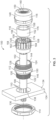
- Figure 1 illustrates a side perspective view of an exemplary cable gland 100 according to an illustrated embodiment of the subject application coupled to a portion, namely a wall 104, of a device.
- the cable gland 100 is configured to couple or secure one or more electrical cables or wires 102 (collectively referred to herein as "cable") to a device, such as, for example, an electrical device, as well provide a seal around and/or between at least a portion of the cable 102 that is within the cable gland 100.
- the cable gland 100 is configured to provide strain relieve to the cable 102, as well as provide sealing for environmental protection of the cable 102 and/or the device.
- Figure 1 shows the cable gland 100 mounted to a wall 104 of the device such that the cable gland 100 securely abuts opposing sides 132a, 132b of the wall 104.
- the cable gland 100 can be made out of one or more materials having suitable properties for an associated application, including strength, weight, and rigidity, among other suitable properties.
- the cable 102 can include an outer jacket 106 that defines a cavity for one or more conductors 108 of the cable 102.
- each of the conductors 108 can be further positioned within an insulative jacket 110, such as, for example, an insulative jacket 110 that can attempt to electrically isolate the conductors 108 from other conductors 108 in the cable 102.
- the conductors 108 can be constructed from a variety of materials, such as, for example, electrically conducive material, including, but not limited to, copper and aluminum, among others.
- the cable gland 100 includes a body portion or gland body 112, a retaining nut 114, a sealing gland 116, and a gland nut 118.
- the cable gland 100 can also include an insert 120.
- the gland body 112, gland nut 118, and retaining nut 114 can be constructed from a variety of materials, including, but not limited to, metal.
- the gland body 112 has a wall 146 that can extend between a first open end 122 and a second open end 124 of the gland body 112. Additionally, the wall 146 of the gland body 112 can include a first external male thread section 126 that is formed about the first open end 122, and a second external male thread section 128 formed about the second open end 124.
- a protruding member 130 can outwardly extend from, as well as extend transversely around, the wall 146 at a location between at least the first and second external male thread sections 126, 128. According to certain embodiments, the outwardly protruding member 130 is configured for mating engagement with a tool, such as, for example, has a generally hexagonal configuration, and is positioned approximately at the middle of the gland body 112.
- the wall 146 and/or gland body 112 can have a variety of different shapes, including, for example, being generally cylindrically shape. Further, an inner side(s) of the wall 146 can define a cavity 134 that extends between opposing openings of the first and second open ends 122, 124 of the gland body 112 that is sized to receive placement of at least a portion of the cable 102, the sealing gland 116, and/or the insert 120.
- the retaining nut 114 extends between a first open end 122 and a second open end 124 of the retaining nut 114, and includes an internal female thread 136 formed on an inner surface of the retaining nut 114 that is configured to threadingly engage and mate the first external male thread section 126 of the gland body 112.
- the retaining nut 114 has a generally cylindrical shape. Additionally, at least a portion of an outer surface of the retaining nut 114 can be configured for a mating engagement with a tool that can assist in securing the retaining nut 114 to the gland body 112, and, moreover, secure the cable gland 100 to the device.
- the outer portion of the retaining nut 114 can have a generally hexagonal shape that is configured for mating engagement with a wrench or ratchet socket, among other tools.
- a wrench or ratchet socket among other tools.
- the gland body 112 when the gland body 112 is positioned within an opening 138 ( Figure 3 ) in the wall 104 of the device such that the first and second external male thread sections 126, 128 are positioned on opposing sides 132a, 132b of the wall 104 ( Figure 1 ) and the internal female threads 136 of the retaining nut 114 are matingly engaged with the first external male thread section 126, one or both of the retaining nut 114 and the gland body 112 can be rotated in a manner that brings the retaining nut 114 into closer proximity to the outwardly protruding member 130 of the gland body 112.
- Such relative displacement of the retaining nut 114 into closer proximity to the outwardly protruding member 130 can facilitate the cable gland 100 being securely pressed against opposing sides 132a, 132b of the wall 104 in a manner that can secure the cable gland 100 to the wall 104 and/or device.
- the gland nut 118 includes an internal female thread 140 formed on an inner surface of the gland nut 118 that is configured to threadingly engage the second external male thread section 128 of the gland body 112.
- the gland nut 118 extends from a first open end 122 to a second open end 124 of the gland nut 118.
- the first open end 122 can include an opening 142 that is sized to accommodate placement of at least a portion of the gland nut 118 about at least the second external male thread section 128 of the gland body 112.
- the second open end 124 can include an opening 144 having a size, such as, for example, diameter, that is smaller than a corresponding size of the opening 142 at the first open end 122 such that the opening 144 at the second open end 124 can at least assist in retaining components of the cable gland 100, such as, for example, the sealing gland 116, at least partially within the cavity 134 of the gland body 112 and/or within the gland nut 118.
- a wall 148 of the gland nut 118 can also define an inner aperture 150 that is positioned to, when the gland nut 118 threadingly engages the second external male thread section 128 of the gland body 112, be in fluid communication with the cavity 134 of the gland body 112 so as to accommodate passage of the cable 102 through the gland nut 118, including through the first and second openings 142, 144 of the gland body 112.
- an outer portion of the gland nut 118 can be configured for mating engagement with a tool, such as, for example, have an outer hexagonal shape.
- a tool such as, for example, have an outer hexagonal shape.
- At least a portion of the insert 120 can, when the cable gland 100 is assembled, be linearly positioned at least between the gland body 112 and the gland nut 118. Additionally, a portion of the insert 120 can be designed to engage within the gland body 112. Further, the insert 120 can be configured to accommodate the sealing gland 116 therewithin, and to provide a mechanism to uniformly compress the sealing gland 116 as the gland nut 118 tightens onto the gland body 112 during installation. While the insert 120 can be constructed from a variety of materials, according to the illustrated embodiment the insert 120 is constructed from plastic.
- the sealing gland 116 of the cable gland 100 is configured to provide a sealant for sealing at least spaces between exposed portions of adjacent conductors 108 and/or insulative jackets 110 of the cable 102, and/or for sealing the cable 102 to the cable gland 100, so as to effectively protect internal portions of the device, the cable 102, and/or the outer environment positioned around the device from hazardous environments and/or ingress of debris into the device. Further, the sealing gland 116 is designed and dimensioned to be closely accommodated within the cavity 134 of the gland body 112, within the insert 120, and/or the gland nut 118 when the gland nut 118 is attached to the gland body 112.
- the sealing gland 116 includes a bushing body 152 having an inner surface 154 and an outer surface 156.
- the inner surface 154 generally defines one or more inner bores 158 that are positioned generally in the center of the bushing body 152.
- the bore(s) 158 is/are sized to accommodate passage of at least a portion of the cable 102 through the bushing body 152.
- the outer surface 156 of the bushing body 152 and is sized to accommodate placement of the bushing body 152 within an interior portion of the cable gland 100, including, for example, within the insert 120, the inner aperture 150 of the gland nut 118, and/or the cavity 134 at or around the second open end 124 of the gland body 112.
- the bushing body 152 can be positioned within the a portion of the gland body 112 and/or insert 120 that is, or will be, beneath at least a portion of the gland nut 118 at least when the cable gland 100 is assembled.
- the bushing body 152 is constructed of a compressible and/or deformable material, such as, for example, a thermoplastic elastomer or rubber, such that, when the gland nut 118 is tightened onto the second external male thread section 128, at least a portion of the bushing body 152 can be radially compressed against the cable 102, such as, for example, against the outer jacket 106 of the cable 102, and/or exposed portions of the insulative jacket 110 or conductors 108. Further, the bushing body 152 can be constructed from a material that is configured to at least provide an environmental protection against hazardous conditions, such as, for example, weather.
- a compressible and/or deformable material such as, for example, a thermoplastic elastomer or rubber
- the insert 120 can include a plurality of arms 162 that are downwardly deflected, deformed, and/or bent against the bushing body 152 when the arms 162 are engaged by an internal surface of the gland nut 118 as an axial position of the gland nut 118 is adjusted via the rotation of the internal female thread 140 of the gland nut 118 about the second external male thread section 128 of the gland body 112.
- the arms 162 may be separated from adjacent arms 162 by a slot 164, which can aid in the downwardly deflection, deformation, and/or bending of the arms 162 against the bushing body 152.
- the outer surface 156 of the bushing body 152 can be linearly displaced along an inwardly tapered surface 166 within the cavity 134 of the gland body 112 by the gland nut 118 as the gland nut 118 is rotated about the second external male thread section 128 in a direction that reduces a distance between the retaining nut 114 and the protruding member 130 of the gland body 112.
- radial compressive forces exerted against the outer surface 156 of the bushing body 152 can increase, thereby compressing the bushing body 152 against the cable 102.
- the bushing body 152 in addition to, or in lieu of, being compressed via use of radial forces, can also be linearly compressed, such as, for example, via exertion of compressive forces against a sidewall(s) 168, 176 of the bushing body 152.
- a first sidewall 168 of the bushing body 152 can abut against an inner wall 170 in the cavity 134 of the gland body 112 or an inner wall 172 within an orifice 174 of the insert 120, while a second sidewall 176 can abut against an inner surface 178 of the gland nut 118.
- the linear distance between the gland nut 118 and the protruding member 130 of the gland body 112 is reduced, such as, for example, via rotation of the gland nut 118 about the second external male thread section 128, the linear distance between the inner surface 178 of the gland nut 118 and the inner wall 170, 172 of the gland body 112 or the insert 120 is reduced in a manner that at least linearly compresses the bushing body 152.
- Such compression of the bushing body 152 can result in a deformation of the bushing body 152 in a manner in which the inner surface 154 of the bushing body 152 exerts a compressive force against at least a portion of the cable 102.
- the sealing gland 116 can also include a sealant 180 that can provide additional environmental protection via forming a seal between at least a portion of the cable gland 100, 100' and the cable 102, as well as a seal in spaces between adjacent conductors 108 and/or adjacent insulative jackets 110 of the cable 102.
- the sealant 180 can be a releasable, and curable, viscous sealant that is, and least prior to rupturing, contained at least partially within a package 182 of the sealing gland 116.
- the sealing gland 116 includes a pressure sensitive or rupturable package 182 that defines at least a portion of an inner area 184 that can, at least temporarily, house a portion of the sealant 180.
- the package 182 can be constructed from a variety of different materials, including, but not limited to, rubber, plastic, or an elastomer, and can be relatively thin, such as, for example, have a wall thickness of around 0.1 millimeters (mm) to about 1 millimeter (mm). Further, according to certain embodiments, the package 182 can be completely enclosed such that, at least prior to rupture, the sealant 180 is entirely housed within the package 182.
- the package 182 defines only a portion of the inner area 184, with another component of the cable gland 100, 100' defining another portion of the inner area 184.
- the package 182 can be coupled or attached to the inner surface 154 of the bushing body 152 such that at least a portion of the inner surface 154 of the bushing body 152 assists in retaining the sealant 180 within, or otherwise defines a portion of, the inner area 184, while the remainder of the inner area 184 is surrounded by the package 182.
- the package 182 can have a variety of different shapes, including, for example, being cylindrically shaped, and be positioned at a variety of locations relative to at least the bushing body 152.
- the package 182 can be positioned within the bore 158, and/or supported by the inner surface 154, of the bushing body 152.
- the package 182 may, or may not, be attached or directly coupled to the bushing body 152.
- the package 182 and bushing body 152 can be separate components such that the package 182 can be separately inserted into, or removed from, the bushing body 152 or other portion of cable gland 100, 100'.
- the package 182 can be adhered to, or otherwise part of, the bushing body 152.
- the package 182 can be secured to the bushing body 152 via an adhesive, among other materials, or may be formed with the bushing body 152, such as, for example, during a multi-shot injection molding process.
- Figures 4 and 5 depict a package 182 having a generally cylindrical shape that is positioned within a bore 158 of the bushing body 152 that may, or may not, be directly attached or coupled to the bushing body 152
- Figure 6A illustrates an embodiment in which the package 182 comprises a plurality of packages 182 that are attached to, or positioned adjacent to, an inner surface 154 the bushing body 152.
- the package 182 can comprise a package(s) 182 that is/are positioned against or adjacent to one or more sidewalls 168, 176 of the bushing body 152 ( Figure 6C ), the outer surface 156 of the bushing body 152 ( Figure 6D ), and/or any combination thereof.
- Figure 6C illustrates a package 182 that is configured to be positioned about an upper portion of the outer surface 156 of the bushing body 152
- the package 182 could also, for example, be positioned at other locations about the outer surface 156, and can include a plurality of packages 182 that can be at a variety of locations about the outer surface 156, and/or be a continuous package 182 that encircles the outer surface 156.
- Figure 6D illustrates a single package 182 adjacent to one sidewall 176 of the bushing body 152
- the package 182 (or an additional package 182) could be positioned adjacent to the other sidewall 168, and/or can comprise a plurality of packages 182 about one or both of the sidewalls 168, 176 of the bushing body 152.
- Figure 6B illustrates another embodiment in which, in addition to, or in lieu of, the previously discussed package 182 locations, one or more packages 182 can be integrated or otherwise formed into the bushing body 152, such as, for example, positioned between opposing first and second portions 186a, 186b of the bushing body 152.
- radial compression on one or both of the first and second portions 186a, 186b of the bushing body 152 can rupture the package 182, thereby releasing the sealant 180.
- opposing ends of the first and second portions 186a, 186b of the bushing body 152 that had been separated by the sealant 180 can move into closer proximity to each other, including, for example, into an abutting engagement.
- sealant 180 of the sealing gland 116 can be used for the sealant 180 of the sealing gland 116, including sealants having a variety of viscosities, and sealants that are, or are not, premixed with other components of the sealant. Additionally, at least certain types of sealant 180 may require a period of time to cure. Examples of curable sealants suitable for use as the sealant 180 include, but are not limited to, silicone based compounds liquid based rubbers, and epoxies, among others. Additionally, according to certain embodiments, the packages 182 can contain different sealants 180 or different portions of the sealant 180, including, for example, a solvent in one or more packages 182 and a bonding agent in another package(s) 182.
- the sealant 180 can be a malleable material, including, but not limited to, a putty. According to such embodiments, the sealant 180 can be positioned at locations similar to those discussed above with respect to the package 182 (as shown in Figures 4-6D ), and may, or may not, be contained within a package(s) 182.
- the package 182 upon compression of at least the bushing body 152 and/or the package 182, the package 182 can burst or otherwise rupture such that the sealant 180 can be released from the package 182.
- the package 182 upon tightening of the gland nut 118 onto the gland body 112 and compressing the cable 102 placed therewithin, compression relating to the arms 162 of the insert 120, radial forces from movement of the bushing body 152 and/or package 182 along the tapered inner surface 166 of the gland body 112, and or axial compression, can result in the sealant 180 being released from the package 182.
- the released sealant 180 can then flow between the cable 102 and adjacent portions of the cable gland 100,100', including, for example, the bushing body 152 and/or gland nut 118, as well as flow into spaces between adjacent conductors 108 and/or insulative jackets 110.
- the curable and viscous sealant 180 can provide a seal not only between the sealing gland 116 and the cable 102, but also within the cable interstitial spaces. Such a configuration is particularly advantageous where the cable 102 includes multiple conductors 108 with interstitial spaces between the conductors 108.
- the sealant 180 is a malleable sealant material that may, or may not, be contained in a package 182
- the above-discussed such compression including compression of at least the bushing body 152, can result in forces that press, squeeze, deform and/or displace at least portions of the sealant 180.
- the forces associated with compression of the bushing body 152 can force the malleable sealant material into locations that result in the malleable sealant material providing a seal between the sealing gland 116 and the cable 102, as well as presses or pushes the malleable material into spaces between exposed portions of the insulative jackets 110 and/or conductors 108 of the cable 102.
- the gland body 112 can first be inserted through the opening 138 defined in the wall 104 or structure of the device until the protruding member 130 of the gland body 112 meets a side 132b of the wall 104.
- the gland body 112 is inserted into the wall 104 such that the first open end 122 of the gland body 112 protrudes from the opening 138 at the first, or left side 132a of the wall 104, and the second open end 124 of the gland body 112 is positioned outside of, or protrudes through the opening 138 to, the right, or second side 132b of the wall 104.
- the retaining nut 114 can then be attached to the gland body 112 by engaging the internal threads 136 of the retaining nut 114 with the first external male thread section 126 at the first open end 122 of the gland body 112, and rotating the retaining nut 114 towards the wall 104 until the retaining nut 114 tightly engages the wall 104.
- the gland nut 118 With the sealing gland 116 positioned within either the gland body 112, the insert 120 that is at least partially secured within the gland body 112, or the gland nut 118, the gland nut 118 is attached to the gland body 112 by engaging the internal threads of the gland nut 118 with the second external male thread section 128 at the second open end 124 of the gland body 112.
- the gland nut 118 then is rotated such that the gland nut 118 is at least linearly displaced towards the protruding member 130 of the gland body 112.
- the sealing gland 116 is compressed such that the package 182 ruptures or bursts, thereby releasing the sealant 180, and/or the sealant 180 is pressed, such that the sealant 180 is positioned to form a seal between the cable 102 and the cable gland 100, 100', as well as in interstitial spaces between the conductors 108 and/or insulative jackets 110.
- the gland nut 118 can continue to be rotated until the gland nut 118 tightly engages the gland body 112 and/or the protruding member 130.
- the cable gland 100, 100' is configured to provide strain relief to the cable 102. Further, this strain relief can provide both sealing and retention to the conductors 108 that run through the wall 104 or structure of a device. Further, from the foregoing, it will be appreciated that a cable gland 100, 100' according to the present application can include a curable or malleable sealant material that may, or may not, be at least temporarily retained in a rupturable package 182 within the cable gland 100, 100' that can provide a sealing for at least environmental protection.
Landscapes
- Engineering & Computer Science (AREA)
- Architecture (AREA)
- Civil Engineering (AREA)
- Structural Engineering (AREA)
- Installation Of Indoor Wiring (AREA)
- Cable Accessories (AREA)
- Processing Of Terminals (AREA)
- Insulated Conductors (AREA)
Claims (6)
- Presse-étoupe de câble (100), comprenant :un corps de presse-étoupe (112) ayant une cavité (134) ;un écrou de serrage (114) configuré pour être sélectivement accouplé à une première extrémité (122) du corps de presse-étoupe (112) ;un écrou de presse-étoupe (118) configuré pour être sélectivement accouplé à une seconde extrémité (124) du corps de presse-étoupe (112) ; etun presse-étoupe d'étanchéité (116) comprenant un corps de douille (152) et un matériau d'étanchéité (180), le corps de douille (152) ayant un alésage (158) qui est en communication fluidique avec la cavité (134), le corps de douille (152) étant configuré pour être dans un état comprimé par le biais d'un accouplement de l'écrou de presse-étoupe (118) au corps de presse-étoupe (112), dans lequel le matériau d'étanchéité (180) est configuré pour le déplacement dans une partie de l'alésage (158) lorsque le corps de douille (152) est dans l'état comprimé,caractérisé en ce quele presse-étoupe d'étanchéité (116) comprend en outre une enveloppe (182), dans lequel l'enveloppe (182) est fixée au corps de douille (152) ; l'enveloppe (182) définissant au moins une partie d'une zone intérieure (184) qui retient le matériau d'étanchéité (180) avant que le corps de douille (152) soit dans l'état comprimé, dans lequel l'enveloppe (182) est configurée pour se rompre lorsque le corps de douille (152) est dans l'état comprimé.
- Presse-étoupe de câble (100) selon la revendication 1, dans lequel le matériau d'étanchéité (180) à l'intérieur de la zone intérieure (184) de l'enveloppe (182) comprend un produit-matériau d'étanchéité durcissable.
- Presse-étoupe de câble (100) selon la revendication 1, dans lequel l'enveloppe (182) comprend une pluralité d'enveloppes (182).
- Presse-étoupe de câble (100) selon la revendication 3, dans lequel au moins une de la pluralité d'enveloppes (182) contient un matériau d'étanchéité (180) différent ou un composant du matériau d'étanchéité (180) différent de celui d'au moins une autre enveloppe (182) de la pluralité de enveloppes (182).
- Presse-étoupe de câble (100) selon la revendication 1, dans lequel le matériau d'étanchéité (180) est un produit-matériau d'étanchéité malléable.
- Presse-étoupe de câble (100) selon la revendication 1, dans lequel, avant que le corps de douille (152) soit dans l'état comprimé, au moins une partie du matériau d'étanchéité (180) est positionnée à l'intérieur de l'alésage (158) du corps de douille (152) ; oudans lequel, avant que le corps de douille (152) soit dans l'état comprimé, au moins une partie du matériau d'étanchéité (180) est positionnée de façon adjacente à au moins une paroi latérale (168, 176) du corps de douille (152) ; oudans lequel, avant que le corps de douille (152) soit dans l'état comprimé, au moins une partie du matériau d'étanchéité (180) est positionnée de façon adjacente à au moins une partie d'une surface extérieure (156) du corps de douille (152) ; oudans lequel, au moins avant que le corps de douille (152) soit dans l'état comprimé, au moins une partie du matériau d'étanchéité (180) est intégrée dans le corps de douille (152).
Applications Claiming Priority (2)
| Application Number | Priority Date | Filing Date | Title |
|---|---|---|---|
| US201762573859P | 2017-10-18 | 2017-10-18 | |
| PCT/US2018/056504 WO2019079590A1 (fr) | 2017-10-18 | 2018-10-18 | Presse-étoupe de câble rempli d'un matériau d'étanchéité |
Publications (4)
| Publication Number | Publication Date |
|---|---|
| EP3698446A1 EP3698446A1 (fr) | 2020-08-26 |
| EP3698446A4 EP3698446A4 (fr) | 2021-08-04 |
| EP3698446B1 true EP3698446B1 (fr) | 2024-02-28 |
| EP3698446B8 EP3698446B8 (fr) | 2024-04-03 |
Family
ID=66097565
Family Applications (1)
| Application Number | Title | Priority Date | Filing Date |
|---|---|---|---|
| EP18868388.2A Active EP3698446B8 (fr) | 2017-10-18 | 2018-10-18 | Presse-étoupe de câble rempli d'un matériau d'étanchéité |
Country Status (5)
| Country | Link |
|---|---|
| US (1) | US10594127B2 (fr) |
| EP (1) | EP3698446B8 (fr) |
| CN (1) | CN111788749B (fr) |
| FI (1) | FI3698446T3 (fr) |
| WO (1) | WO2019079590A1 (fr) |
Families Citing this family (16)
| Publication number | Priority date | Publication date | Assignee | Title |
|---|---|---|---|---|
| KR102533636B1 (ko) * | 2016-12-30 | 2023-05-17 | 뉴스케일 파워, 엘엘씨 | 격납 시일부 |
| WO2018172851A1 (fr) * | 2017-03-20 | 2018-09-27 | Pentair Flow Services Ag | Presse-étoupe d'étanchéité et procédés de fixation d'une extrémité d'un câble à une enceinte |
| CA3072692A1 (fr) * | 2017-09-18 | 2019-03-21 | Cmp Products Limited | Appareil de distribution de materiau durcissable dans un presse-etoupe de cable |
| GB201808026D0 (en) * | 2018-05-17 | 2018-07-04 | Hubbell Ltd | Cable gland |
| US11855422B2 (en) * | 2018-10-12 | 2023-12-26 | Eaton Intelligent Power Limited | Cable gland including internal dam |
| USD913332S1 (en) * | 2018-11-02 | 2021-03-16 | Nidec Motor Corporation | Motor conduit plug |
| GB2590720B (en) * | 2019-12-31 | 2022-11-16 | Ccg International Holdings Ltd | Resin pot component for an inspectable barrier cable gland |
| USD1009802S1 (en) * | 2020-01-31 | 2024-01-02 | CCG International Holdings Limited | Cable gland |
| EP3886281A1 (fr) * | 2020-03-24 | 2021-09-29 | ABB Schweiz AG | Ensemble de traversée |
| CA3176241A1 (fr) | 2020-05-13 | 2021-11-18 | GAF Energy LLC | Passe-cable electrique |
| US11545928B2 (en) | 2020-10-13 | 2023-01-03 | GAF Energy LLC | Solar roofing system |
| US12009781B2 (en) | 2021-07-06 | 2024-06-11 | GAF Energy LLC | Jumper module for photovoltaic systems |
| US12230927B2 (en) * | 2021-11-10 | 2025-02-18 | Eaton Intelligent Power Limited | Cable gland with torque sensor |
| PL246863B1 (pl) * | 2022-02-09 | 2025-03-17 | Produced In Internet Spolka Z Ograniczona Odpowiedzialnoscia | Sposób i dławica do mocowania przewodu, zwłaszcza elektrycznego |
| EP4246744A1 (fr) * | 2022-03-15 | 2023-09-20 | Yazaki Europe Ltd. | Ensemble câble électrique blindé |
| EP4544650A1 (fr) * | 2022-05-30 | 2025-04-30 | Bimed Teknik Aletler Sanayi ve Ticaret Anonim Sirketi | Éléments de raccordement de câble |
Family Cites Families (29)
| Publication number | Priority date | Publication date | Assignee | Title |
|---|---|---|---|---|
| US4549755A (en) * | 1983-06-16 | 1985-10-29 | Efcor, Inc. | Armored cable connector |
| US4590329A (en) * | 1985-01-18 | 1986-05-20 | Westinghouse Electric Corp. | Protective enclosure for splice connection |
| US4662692A (en) | 1985-05-02 | 1987-05-05 | Raychem Corp. | Sealing member |
| US4692562A (en) * | 1985-09-26 | 1987-09-08 | Commander Electrical Materials, Inc. | Seal for a cable connector |
| GB8922355D0 (en) | 1989-10-04 | 1989-11-22 | British Telecomm | Sealing gland |
| US5015804A (en) * | 1990-03-26 | 1991-05-14 | Commander Electrical Materials, Inc. | Electrical cable connector for sealing an armoured electrical cable |
| GB2244388B (en) * | 1990-04-24 | 1994-06-22 | C M P | Improvements in cable glands |
| GB2258350B (en) | 1991-07-20 | 1995-08-02 | Hawke Cable Glands Ltd | Electric cable barrier gland |
| GB2284716B (en) | 1993-11-03 | 1998-03-04 | Framatome Connectors Int | Improvements relating to cable sealing arrangements |
| DE19636119A1 (de) | 1996-09-06 | 1998-03-12 | Teves Gmbh Alfred | Steckverbindung zur Herstellung eines feuchtigkeitsdichten elektrischen Übergangs |
| GB9814399D0 (en) * | 1998-07-03 | 1998-09-02 | Raychem Sa Nv | A seal |
| JP2000150057A (ja) | 1998-11-16 | 2000-05-30 | Sumitomo Wiring Syst Ltd | 防水コネクタ |
| WO2001090607A2 (fr) * | 2000-05-23 | 2001-11-29 | Tdm Industries, Inc. | Element formant un joint souple |
| GB0104083D0 (en) | 2001-02-20 | 2001-04-04 | Hawke Cable Glands Ltd | Cable gland assembly |
| US7014502B2 (en) | 2003-04-04 | 2006-03-21 | Anlynk Wireless, Llc | RF feedthrough coaxial connector for wireless communications in hazardous environments |
| DE202005014138U1 (de) | 2005-09-07 | 2005-11-10 | Anton Hummel Verwaltungs-Gmbh | Bausatz oder Set umfassend wenigstens zwei unterschiedlich bemessene Typen von Kabelverschraubungen |
| US7288719B2 (en) | 2006-01-19 | 2007-10-30 | Conax Buffalo Technologies Llc | Hazardous location sealing gland |
| JP2010087139A (ja) * | 2008-09-30 | 2010-04-15 | Mitsubishi Electric Corp | 気密端子 |
| US7960652B2 (en) * | 2008-10-02 | 2011-06-14 | Delphi Technologies, Inc. | Sealed cable and terminal crimp |
| SG178839A1 (en) * | 2009-08-21 | 2012-04-27 | Cmp Products Ltd | Filler assembly for cable gland |
| GB2479874A (en) | 2010-04-26 | 2011-11-02 | Cable Man Products Ltd | Barrier connector sleeve |
| DE102011110380B3 (de) | 2011-08-17 | 2012-07-26 | Johnson Electric Dresden Gmbh | Fluiddichte Kabeldurchführung für Flachbandkabel |
| US8845361B2 (en) * | 2011-11-08 | 2014-09-30 | Thomas & Betts International Llc | Explosion-proof electrical fitting |
| US8979590B2 (en) * | 2012-07-26 | 2015-03-17 | Thomas & Betts International, Llc | Cable gland for electrical cable fitting |
| US9343890B2 (en) * | 2013-01-23 | 2016-05-17 | Thomas & Betts International Llc | Electrical cable restrain device using a double wedge chuck |
| CN204316068U (zh) * | 2015-01-13 | 2015-05-06 | 上海蓝科电气有限公司 | 电缆耐高压防水接头 |
| CN104795784B (zh) * | 2015-04-23 | 2018-01-02 | 倍仕得电气科技(杭州)股份有限公司 | 防屏蔽金属电缆固定头及装配屏蔽密封方法 |
| US9640965B1 (en) | 2016-03-25 | 2017-05-02 | Protonex Technology Corporation | Cable gland assembly |
| CA3072692A1 (fr) * | 2017-09-18 | 2019-03-21 | Cmp Products Limited | Appareil de distribution de materiau durcissable dans un presse-etoupe de cable |
-
2018
- 2018-10-18 WO PCT/US2018/056504 patent/WO2019079590A1/fr not_active Ceased
- 2018-10-18 EP EP18868388.2A patent/EP3698446B8/fr active Active
- 2018-10-18 FI FIEP18868388.2T patent/FI3698446T3/fi active
- 2018-10-18 CN CN201880081311.1A patent/CN111788749B/zh active Active
- 2018-10-18 US US16/164,300 patent/US10594127B2/en active Active
Also Published As
| Publication number | Publication date |
|---|---|
| CN111788749A (zh) | 2020-10-16 |
| EP3698446B8 (fr) | 2024-04-03 |
| FI3698446T3 (fi) | 2024-05-27 |
| CN111788749B (zh) | 2021-09-28 |
| EP3698446A4 (fr) | 2021-08-04 |
| US20190115743A1 (en) | 2019-04-18 |
| EP3698446A1 (fr) | 2020-08-26 |
| WO2019079590A1 (fr) | 2019-04-25 |
| US10594127B2 (en) | 2020-03-17 |
Similar Documents
| Publication | Publication Date | Title |
|---|---|---|
| EP3698446B1 (fr) | Presse-étoupe de câble rempli d'un matériau d'étanchéité | |
| EP1241736B1 (fr) | Dispositif de bornes de connexion | |
| US9263867B2 (en) | Clamp ring, cable screw connection and method for assembling a cable screw connection | |
| US9735561B2 (en) | Explosion-proof cable connecting assembly | |
| EP3076487B1 (fr) | Bague de passe-fil en plastique pour une liaison de conducteur, piece de liaison, ecrou de recouvrement et liaison etanche entre deux conducteurs | |
| EP0637116A1 (fr) | Dispositif de protection d'épissure de câbles | |
| US5310963A (en) | Electric cable barrier gland | |
| KR100337568B1 (ko) | 케이블밀봉장치 | |
| JP2622480B2 (ja) | 電気ケーブルの保護包摂方法及び装置 | |
| JPH077837A (ja) | ケーブルグランド | |
| EP0217653A2 (fr) | Indicateur de compression | |
| CN1918752A (zh) | 带有弹性体带的电缆连接器 | |
| EP3132506B1 (fr) | Embout de câble | |
| JPH05276619A (ja) | ケーブルスプライス装置 | |
| CA2106468A1 (fr) | Disposition de connexion de cable coaxial/douille-contact | |
| US4814547A (en) | Cable connector | |
| JP2005123195A (ja) | 改善されたケーブルシール部を備えたプラグケーシング | |
| US5792987A (en) | Sealing device | |
| KR101557023B1 (ko) | 콤파운드와 패킹을 이용한 기밀 고정구조를 갖는 케이블 실링장치 | |
| ITGE20060051A1 (it) | Dispositivo di connessione per collegamenti elettrici od elettronici. | |
| JP7143189B2 (ja) | ケーブル接続部 | |
| KR20000076339A (ko) | 케이블 접속 폐쇄장치용 외부 접지 절연 커넥터 | |
| JPH1064630A (ja) | コネクタハウジングの取り付け構造 | |
| US20120037419A1 (en) | Cable termination apparatus and related methods | |
| US6863567B2 (en) | Electrical wiring with strain relief |
Legal Events
| Date | Code | Title | Description |
|---|---|---|---|
| STAA | Information on the status of an ep patent application or granted ep patent |
Free format text: STATUS: THE INTERNATIONAL PUBLICATION HAS BEEN MADE |
|
| PUAI | Public reference made under article 153(3) epc to a published international application that has entered the european phase |
Free format text: ORIGINAL CODE: 0009012 |
|
| STAA | Information on the status of an ep patent application or granted ep patent |
Free format text: STATUS: REQUEST FOR EXAMINATION WAS MADE |
|
| 17P | Request for examination filed |
Effective date: 20200618 |
|
| AK | Designated contracting states |
Kind code of ref document: A1 Designated state(s): AL AT BE BG CH CY CZ DE DK EE ES FI FR GB GR HR HU IE IS IT LI LT LU LV MC MK MT NL NO PL PT RO RS SE SI SK SM TR |
|
| AX | Request for extension of the european patent |
Extension state: BA ME |
|
| DAV | Request for validation of the european patent (deleted) | ||
| DAX | Request for extension of the european patent (deleted) | ||
| A4 | Supplementary search report drawn up and despatched |
Effective date: 20210701 |
|
| RIC1 | Information provided on ipc code assigned before grant |
Ipc: H02G 15/007 20060101AFI20210625BHEP Ipc: H02G 15/013 20060101ALI20210625BHEP Ipc: H02G 15/04 20060101ALI20210625BHEP |
|
| STAA | Information on the status of an ep patent application or granted ep patent |
Free format text: STATUS: EXAMINATION IS IN PROGRESS |
|
| 17Q | First examination report despatched |
Effective date: 20220922 |
|
| GRAP | Despatch of communication of intention to grant a patent |
Free format text: ORIGINAL CODE: EPIDOSNIGR1 |
|
| STAA | Information on the status of an ep patent application or granted ep patent |
Free format text: STATUS: GRANT OF PATENT IS INTENDED |
|
| INTG | Intention to grant announced |
Effective date: 20230912 |
|
| GRAS | Grant fee paid |
Free format text: ORIGINAL CODE: EPIDOSNIGR3 |
|
| GRAA | (expected) grant |
Free format text: ORIGINAL CODE: 0009210 |
|
| STAA | Information on the status of an ep patent application or granted ep patent |
Free format text: STATUS: THE PATENT HAS BEEN GRANTED |
|
| AK | Designated contracting states |
Kind code of ref document: B1 Designated state(s): AL AT BE BG CH CY CZ DE DK EE ES FI FR GB GR HR HU IE IS IT LI LT LU LV MC MK MT NL NO PL PT RO RS SE SI SK SM TR |
|
| REG | Reference to a national code |
Ref country code: GB Ref legal event code: FG4D |
|
| REG | Reference to a national code |
Ref country code: CH Ref legal event code: EP |
|
| REG | Reference to a national code |
Ref country code: DE Ref legal event code: R096 Ref document number: 602018066000 Country of ref document: DE |
|
| REG | Reference to a national code |
Ref country code: CH Ref legal event code: PK Free format text: BERICHTIGUNG B8 |
|
| RAP2 | Party data changed (patent owner data changed or rights of a patent transferred) |
Owner name: ABB SCHWEIZ AG |
|
| REG | Reference to a national code |
Ref country code: IE Ref legal event code: FG4D |
|
| REG | Reference to a national code |
Ref country code: DE Ref legal event code: R081 Ref document number: 602018066000 Country of ref document: DE Owner name: ABB SCHWEIZ AG, CH Free format text: FORMER OWNER: THOMAS & BETTS INTERNATIONAL LLC, WILMINGTON, DE, US |
|
| REG | Reference to a national code |
Ref country code: FI Ref legal event code: FGE |
|
| REG | Reference to a national code |
Ref country code: SE Ref legal event code: TRGR |
|
| REG | Reference to a national code |
Ref country code: LT Ref legal event code: MG9D |
|
| PG25 | Lapsed in a contracting state [announced via postgrant information from national office to epo] |
Ref country code: IS Free format text: LAPSE BECAUSE OF FAILURE TO SUBMIT A TRANSLATION OF THE DESCRIPTION OR TO PAY THE FEE WITHIN THE PRESCRIBED TIME-LIMIT Effective date: 20240628 |
|
| REG | Reference to a national code |
Ref country code: NL Ref legal event code: MP Effective date: 20240228 |
|
| PG25 | Lapsed in a contracting state [announced via postgrant information from national office to epo] |
Ref country code: LT Free format text: LAPSE BECAUSE OF FAILURE TO SUBMIT A TRANSLATION OF THE DESCRIPTION OR TO PAY THE FEE WITHIN THE PRESCRIBED TIME-LIMIT Effective date: 20240228 |
|
| PG25 | Lapsed in a contracting state [announced via postgrant information from national office to epo] |
Ref country code: GR Free format text: LAPSE BECAUSE OF FAILURE TO SUBMIT A TRANSLATION OF THE DESCRIPTION OR TO PAY THE FEE WITHIN THE PRESCRIBED TIME-LIMIT Effective date: 20240529 |
|
| PG25 | Lapsed in a contracting state [announced via postgrant information from national office to epo] |
Ref country code: HR Free format text: LAPSE BECAUSE OF FAILURE TO SUBMIT A TRANSLATION OF THE DESCRIPTION OR TO PAY THE FEE WITHIN THE PRESCRIBED TIME-LIMIT Effective date: 20240228 Ref country code: RS Free format text: LAPSE BECAUSE OF FAILURE TO SUBMIT A TRANSLATION OF THE DESCRIPTION OR TO PAY THE FEE WITHIN THE PRESCRIBED TIME-LIMIT Effective date: 20240528 Ref country code: NL Free format text: LAPSE BECAUSE OF FAILURE TO SUBMIT A TRANSLATION OF THE DESCRIPTION OR TO PAY THE FEE WITHIN THE PRESCRIBED TIME-LIMIT Effective date: 20240228 |
|
| PG25 | Lapsed in a contracting state [announced via postgrant information from national office to epo] |
Ref country code: ES Free format text: LAPSE BECAUSE OF FAILURE TO SUBMIT A TRANSLATION OF THE DESCRIPTION OR TO PAY THE FEE WITHIN THE PRESCRIBED TIME-LIMIT Effective date: 20240228 |
|
| PG25 | Lapsed in a contracting state [announced via postgrant information from national office to epo] |
Ref country code: RS Free format text: LAPSE BECAUSE OF FAILURE TO SUBMIT A TRANSLATION OF THE DESCRIPTION OR TO PAY THE FEE WITHIN THE PRESCRIBED TIME-LIMIT Effective date: 20240528 Ref country code: NO Free format text: LAPSE BECAUSE OF FAILURE TO SUBMIT A TRANSLATION OF THE DESCRIPTION OR TO PAY THE FEE WITHIN THE PRESCRIBED TIME-LIMIT Effective date: 20240528 Ref country code: NL Free format text: LAPSE BECAUSE OF FAILURE TO SUBMIT A TRANSLATION OF THE DESCRIPTION OR TO PAY THE FEE WITHIN THE PRESCRIBED TIME-LIMIT Effective date: 20240228 Ref country code: LT Free format text: LAPSE BECAUSE OF FAILURE TO SUBMIT A TRANSLATION OF THE DESCRIPTION OR TO PAY THE FEE WITHIN THE PRESCRIBED TIME-LIMIT Effective date: 20240228 Ref country code: IS Free format text: LAPSE BECAUSE OF FAILURE TO SUBMIT A TRANSLATION OF THE DESCRIPTION OR TO PAY THE FEE WITHIN THE PRESCRIBED TIME-LIMIT Effective date: 20240628 Ref country code: HR Free format text: LAPSE BECAUSE OF FAILURE TO SUBMIT A TRANSLATION OF THE DESCRIPTION OR TO PAY THE FEE WITHIN THE PRESCRIBED TIME-LIMIT Effective date: 20240228 Ref country code: GR Free format text: LAPSE BECAUSE OF FAILURE TO SUBMIT A TRANSLATION OF THE DESCRIPTION OR TO PAY THE FEE WITHIN THE PRESCRIBED TIME-LIMIT Effective date: 20240529 Ref country code: ES Free format text: LAPSE BECAUSE OF FAILURE TO SUBMIT A TRANSLATION OF THE DESCRIPTION OR TO PAY THE FEE WITHIN THE PRESCRIBED TIME-LIMIT Effective date: 20240228 Ref country code: BG Free format text: LAPSE BECAUSE OF FAILURE TO SUBMIT A TRANSLATION OF THE DESCRIPTION OR TO PAY THE FEE WITHIN THE PRESCRIBED TIME-LIMIT Effective date: 20240228 |
|
| PG25 | Lapsed in a contracting state [announced via postgrant information from national office to epo] |
Ref country code: PL Free format text: LAPSE BECAUSE OF FAILURE TO SUBMIT A TRANSLATION OF THE DESCRIPTION OR TO PAY THE FEE WITHIN THE PRESCRIBED TIME-LIMIT Effective date: 20240228 Ref country code: PT Free format text: LAPSE BECAUSE OF FAILURE TO SUBMIT A TRANSLATION OF THE DESCRIPTION OR TO PAY THE FEE WITHIN THE PRESCRIBED TIME-LIMIT Effective date: 20240628 |
|
| REG | Reference to a national code |
Ref country code: AT Ref legal event code: MK05 Ref document number: 1662140 Country of ref document: AT Kind code of ref document: T Effective date: 20240228 |
|
| PG25 | Lapsed in a contracting state [announced via postgrant information from national office to epo] |
Ref country code: PT Free format text: LAPSE BECAUSE OF FAILURE TO SUBMIT A TRANSLATION OF THE DESCRIPTION OR TO PAY THE FEE WITHIN THE PRESCRIBED TIME-LIMIT Effective date: 20240628 Ref country code: PL Free format text: LAPSE BECAUSE OF FAILURE TO SUBMIT A TRANSLATION OF THE DESCRIPTION OR TO PAY THE FEE WITHIN THE PRESCRIBED TIME-LIMIT Effective date: 20240228 Ref country code: LV Free format text: LAPSE BECAUSE OF FAILURE TO SUBMIT A TRANSLATION OF THE DESCRIPTION OR TO PAY THE FEE WITHIN THE PRESCRIBED TIME-LIMIT Effective date: 20240228 |
|
| PG25 | Lapsed in a contracting state [announced via postgrant information from national office to epo] |
Ref country code: DK Free format text: LAPSE BECAUSE OF FAILURE TO SUBMIT A TRANSLATION OF THE DESCRIPTION OR TO PAY THE FEE WITHIN THE PRESCRIBED TIME-LIMIT Effective date: 20240228 |
|
| PG25 | Lapsed in a contracting state [announced via postgrant information from national office to epo] |
Ref country code: SM Free format text: LAPSE BECAUSE OF FAILURE TO SUBMIT A TRANSLATION OF THE DESCRIPTION OR TO PAY THE FEE WITHIN THE PRESCRIBED TIME-LIMIT Effective date: 20240228 |
|
| PG25 | Lapsed in a contracting state [announced via postgrant information from national office to epo] |
Ref country code: CZ Free format text: LAPSE BECAUSE OF FAILURE TO SUBMIT A TRANSLATION OF THE DESCRIPTION OR TO PAY THE FEE WITHIN THE PRESCRIBED TIME-LIMIT Effective date: 20240228 Ref country code: EE Free format text: LAPSE BECAUSE OF FAILURE TO SUBMIT A TRANSLATION OF THE DESCRIPTION OR TO PAY THE FEE WITHIN THE PRESCRIBED TIME-LIMIT Effective date: 20240228 |
|
| PG25 | Lapsed in a contracting state [announced via postgrant information from national office to epo] |
Ref country code: AT Free format text: LAPSE BECAUSE OF FAILURE TO SUBMIT A TRANSLATION OF THE DESCRIPTION OR TO PAY THE FEE WITHIN THE PRESCRIBED TIME-LIMIT Effective date: 20240228 |
|
| PG25 | Lapsed in a contracting state [announced via postgrant information from national office to epo] |
Ref country code: SK Free format text: LAPSE BECAUSE OF FAILURE TO SUBMIT A TRANSLATION OF THE DESCRIPTION OR TO PAY THE FEE WITHIN THE PRESCRIBED TIME-LIMIT Effective date: 20240228 |
|
| PG25 | Lapsed in a contracting state [announced via postgrant information from national office to epo] |
Ref country code: SM Free format text: LAPSE BECAUSE OF FAILURE TO SUBMIT A TRANSLATION OF THE DESCRIPTION OR TO PAY THE FEE WITHIN THE PRESCRIBED TIME-LIMIT Effective date: 20240228 Ref country code: SK Free format text: LAPSE BECAUSE OF FAILURE TO SUBMIT A TRANSLATION OF THE DESCRIPTION OR TO PAY THE FEE WITHIN THE PRESCRIBED TIME-LIMIT Effective date: 20240228 Ref country code: RO Free format text: LAPSE BECAUSE OF FAILURE TO SUBMIT A TRANSLATION OF THE DESCRIPTION OR TO PAY THE FEE WITHIN THE PRESCRIBED TIME-LIMIT Effective date: 20240228 Ref country code: EE Free format text: LAPSE BECAUSE OF FAILURE TO SUBMIT A TRANSLATION OF THE DESCRIPTION OR TO PAY THE FEE WITHIN THE PRESCRIBED TIME-LIMIT Effective date: 20240228 Ref country code: DK Free format text: LAPSE BECAUSE OF FAILURE TO SUBMIT A TRANSLATION OF THE DESCRIPTION OR TO PAY THE FEE WITHIN THE PRESCRIBED TIME-LIMIT Effective date: 20240228 Ref country code: CZ Free format text: LAPSE BECAUSE OF FAILURE TO SUBMIT A TRANSLATION OF THE DESCRIPTION OR TO PAY THE FEE WITHIN THE PRESCRIBED TIME-LIMIT Effective date: 20240228 Ref country code: AT Free format text: LAPSE BECAUSE OF FAILURE TO SUBMIT A TRANSLATION OF THE DESCRIPTION OR TO PAY THE FEE WITHIN THE PRESCRIBED TIME-LIMIT Effective date: 20240228 |
|
| REG | Reference to a national code |
Ref country code: DE Ref legal event code: R097 Ref document number: 602018066000 Country of ref document: DE |
|
| PG25 | Lapsed in a contracting state [announced via postgrant information from national office to epo] |
Ref country code: IT Free format text: LAPSE BECAUSE OF FAILURE TO SUBMIT A TRANSLATION OF THE DESCRIPTION OR TO PAY THE FEE WITHIN THE PRESCRIBED TIME-LIMIT Effective date: 20240228 |
|
| PG25 | Lapsed in a contracting state [announced via postgrant information from national office to epo] |
Ref country code: IT Free format text: LAPSE BECAUSE OF FAILURE TO SUBMIT A TRANSLATION OF THE DESCRIPTION OR TO PAY THE FEE WITHIN THE PRESCRIBED TIME-LIMIT Effective date: 20240228 |
|
| PLBE | No opposition filed within time limit |
Free format text: ORIGINAL CODE: 0009261 |
|
| STAA | Information on the status of an ep patent application or granted ep patent |
Free format text: STATUS: NO OPPOSITION FILED WITHIN TIME LIMIT |
|
| 26N | No opposition filed |
Effective date: 20241129 |
|
| PG25 | Lapsed in a contracting state [announced via postgrant information from national office to epo] |
Ref country code: SI Free format text: LAPSE BECAUSE OF FAILURE TO SUBMIT A TRANSLATION OF THE DESCRIPTION OR TO PAY THE FEE WITHIN THE PRESCRIBED TIME-LIMIT Effective date: 20240228 |
|
| REG | Reference to a national code |
Ref country code: CH Ref legal event code: PL |
|
| PG25 | Lapsed in a contracting state [announced via postgrant information from national office to epo] |
Ref country code: MC Free format text: LAPSE BECAUSE OF FAILURE TO SUBMIT A TRANSLATION OF THE DESCRIPTION OR TO PAY THE FEE WITHIN THE PRESCRIBED TIME-LIMIT Effective date: 20240228 |
|
| PG25 | Lapsed in a contracting state [announced via postgrant information from national office to epo] |
Ref country code: BE Free format text: LAPSE BECAUSE OF NON-PAYMENT OF DUE FEES Effective date: 20241031 Ref country code: LU Free format text: LAPSE BECAUSE OF NON-PAYMENT OF DUE FEES Effective date: 20241018 |
|
| PG25 | Lapsed in a contracting state [announced via postgrant information from national office to epo] |
Ref country code: FR Free format text: LAPSE BECAUSE OF NON-PAYMENT OF DUE FEES Effective date: 20241031 |
|
| PG25 | Lapsed in a contracting state [announced via postgrant information from national office to epo] |
Ref country code: CH Free format text: LAPSE BECAUSE OF NON-PAYMENT OF DUE FEES Effective date: 20241031 |
|
| REG | Reference to a national code |
Ref country code: BE Ref legal event code: MM Effective date: 20241031 |
|
| PG25 | Lapsed in a contracting state [announced via postgrant information from national office to epo] |
Ref country code: IE Free format text: LAPSE BECAUSE OF NON-PAYMENT OF DUE FEES Effective date: 20241018 |
|
| PGFP | Annual fee paid to national office [announced via postgrant information from national office to epo] |
Ref country code: DE Payment date: 20251021 Year of fee payment: 8 |
|
| PGFP | Annual fee paid to national office [announced via postgrant information from national office to epo] |
Ref country code: GB Payment date: 20251022 Year of fee payment: 8 |
|
| PGFP | Annual fee paid to national office [announced via postgrant information from national office to epo] |
Ref country code: FI Payment date: 20251028 Year of fee payment: 8 |
|
| PGFP | Annual fee paid to national office [announced via postgrant information from national office to epo] |
Ref country code: SE Payment date: 20251021 Year of fee payment: 8 |
|
| PG25 | Lapsed in a contracting state [announced via postgrant information from national office to epo] |
Ref country code: CY Free format text: LAPSE BECAUSE OF FAILURE TO SUBMIT A TRANSLATION OF THE DESCRIPTION OR TO PAY THE FEE WITHIN THE PRESCRIBED TIME-LIMIT; INVALID AB INITIO Effective date: 20181018 |
|
| PG25 | Lapsed in a contracting state [announced via postgrant information from national office to epo] |
Ref country code: HU Free format text: LAPSE BECAUSE OF FAILURE TO SUBMIT A TRANSLATION OF THE DESCRIPTION OR TO PAY THE FEE WITHIN THE PRESCRIBED TIME-LIMIT; INVALID AB INITIO Effective date: 20181018 |