EP3699110A1 - Support d'un matériau plat pliable pour des produits, de préférence, en petites pièces - Google Patents
Support d'un matériau plat pliable pour des produits, de préférence, en petites pièces Download PDFInfo
- Publication number
- EP3699110A1 EP3699110A1 EP20157087.6A EP20157087A EP3699110A1 EP 3699110 A1 EP3699110 A1 EP 3699110A1 EP 20157087 A EP20157087 A EP 20157087A EP 3699110 A1 EP3699110 A1 EP 3699110A1
- Authority
- EP
- European Patent Office
- Prior art keywords
- fold line
- support
- top wall
- wall
- intermediate floor
- Prior art date
- Legal status (The legal status is an assumption and is not a legal conclusion. Google has not performed a legal analysis and makes no representation as to the accuracy of the status listed.)
- Withdrawn
Links
Images


Classifications
-
- B—PERFORMING OPERATIONS; TRANSPORTING
- B65—CONVEYING; PACKING; STORING; HANDLING THIN OR FILAMENTARY MATERIAL
- B65D—CONTAINERS FOR STORAGE OR TRANSPORT OF ARTICLES OR MATERIALS, e.g. BAGS, BARRELS, BOTTLES, BOXES, CANS, CARTONS, CRATES, DRUMS, JARS, TANKS, HOPPERS, FORWARDING CONTAINERS; ACCESSORIES, CLOSURES, OR FITTINGS THEREFOR; PACKAGING ELEMENTS; PACKAGES
- B65D85/00—Containers, packaging elements or packages, specially adapted for particular articles or materials
- B65D85/60—Containers, packaging elements or packages, specially adapted for particular articles or materials for sweets or like confectionery products
-
- B—PERFORMING OPERATIONS; TRANSPORTING
- B65—CONVEYING; PACKING; STORING; HANDLING THIN OR FILAMENTARY MATERIAL
- B65D—CONTAINERS FOR STORAGE OR TRANSPORT OF ARTICLES OR MATERIALS, e.g. BAGS, BARRELS, BOTTLES, BOXES, CANS, CARTONS, CRATES, DRUMS, JARS, TANKS, HOPPERS, FORWARDING CONTAINERS; ACCESSORIES, CLOSURES, OR FITTINGS THEREFOR; PACKAGING ELEMENTS; PACKAGES
- B65D5/00—Rigid or semi-rigid containers of polygonal cross-section, e.g. boxes, cartons or trays, formed by folding or erecting one or more blanks made of paper
- B65D5/42—Details of containers or of foldable or erectable container blanks
- B65D5/44—Integral, inserted or attached portions forming internal or external fittings
- B65D5/50—Internal supporting or protecting elements for contents
- B65D5/5028—Elements formed separately from the container body
- B65D5/5035—Paper elements
- B65D5/5038—Tray-like elements formed by folding a blank and presenting openings or recesses
-
- B—PERFORMING OPERATIONS; TRANSPORTING
- B65—CONVEYING; PACKING; STORING; HANDLING THIN OR FILAMENTARY MATERIAL
- B65D—CONTAINERS FOR STORAGE OR TRANSPORT OF ARTICLES OR MATERIALS, e.g. BAGS, BARRELS, BOTTLES, BOXES, CANS, CARTONS, CRATES, DRUMS, JARS, TANKS, HOPPERS, FORWARDING CONTAINERS; ACCESSORIES, CLOSURES, OR FITTINGS THEREFOR; PACKAGING ELEMENTS; PACKAGES
- B65D71/00—Bundles of articles held together by packaging elements for convenience of storage or transport, e.g. portable segregating carrier for plural receptacles such as beer cans or pop bottles; Bales of material
- B65D71/70—Trays provided with projections or recesses in order to assemble multiple articles, e.g. intermediate elements for stacking
- B65D71/72—Trays provided with projections or recesses in order to assemble multiple articles, e.g. intermediate elements for stacking formed by folding one or more blanks, the articles being inserted in openings in a wall
Definitions
- the invention relates to a carrier (tray) made of cardboard or some other foldable flat material for pralines or other preferably small-piece products.
- Packagings for chocolates which contain a polystyrene carrier deep-drawn with a vacuum tool into which the chocolates are inserted.
- the carrier comprises a wall on which a plurality of pits are formed which protrude from the underside of the wall.
- Each bowl has a surrounding shoulder on which a praline is placed so that it protrudes over the top of the wall.
- a raised side edge runs around the wall to stabilize the support.
- a large number of carriers are nested in stacks and delivered to the manufacturer of the pralines. There the carriers are automatically filled with chocolates and the filled carriers are placed in hollow-wall boxes or other folding boxes so that the recesses sit with their dome-shaped undersides on the bottom wall.
- a paper pillow is placed on top of the pralines and the box is closed. This fixes the pralines between the paper cushion and the carrier.
- the calottes and the paper fleece can deform under pressure, which prevents damage to the pralines.
- the invention is based on the object of providing a carrier for chocolates or other preferably small-piece products that can be used for chocolates or other small-piece products with different shapes, sizes, Arrangements and / or numbers can be produced more easily and at lower costs.
- the small-piece products can be inserted into the openings so that they are supported at the bottom on the intermediate floor and protrude above the top of the top wall.
- the contours of the openings can be adapted to the contours of the small-sized products so that they can be fixed in the openings. Because the intermediate floor is at a distance from the base wall, the base wall can yield, so that pralines or other small-piece products can evade increased pressure loads without being damaged.
- the carrier according to the invention can easily be provided for different shapes, sizes, arrangements and / or numbers of small-piece products. All that needs to be done is the shape, size, arrangement and / or Number of openings in the top wall and the first distance between the intermediate floor and the top wall can be adjusted.
- Punching tools for the production of blanks from cardboard or another foldable flat material from which the carriers are formed can be provided with relatively little effort and cost. Effort and costs for the production of the corresponding injection molding tools are eliminated.
- the carrier consisting of the top wall, bottom wall, intermediate floor and side tabs can be made particularly stable. This is advantageous for the automatic insertion of the carrier into a folding box and the protection of the small-piece products from damage.
- the second distance between the intermediate floor and the floor wall can be kept small so that the carrier gets by with little material.
- the openings are arranged in parallel rows and side by side in parallel columns. This is particularly advantageous for space-saving storage of small-piece products with the same shape and size. However, other regular or irregular arrangements of the openings can also be selected.
- the openings have one or more of the following contours: circular, oval, triangular, square or in some other way angular, sickle-shaped, lenticular.
- the openings can have any other desired closed contours.
- the top wall, the intermediate floor and the bottom wall are rectangular.
- the carrier has a particularly stable box profile.
- this is advantageous for the material-saving production and the space-saving storage of the carriers and packaging containing them.
- the top wall, the intermediate base and the base wall are polygonal with more than four corners, circular, oval, heart-shaped, sickle-shaped, lens-shaped or have a contour that is closed in some other way.
- the top wall, the bottom wall and the side wall are connected to one another along straight, parallel edges by side tabs, so that the carrier can be folded flat.
- the side flaps can be made narrow, so that the straight edges are short and only make up a small part of the entire contour.
- the closed contours can deviate from a circular, oval or other curved contour.
- side flaps are only present on two opposite edges of the top wall, intermediate floor and bottom wall. The remaining edges of the top wall, bottom wall and intermediate floor are free of side flaps.
- the carrier can be folded flat. This enables space-saving storage in stacks for storage and transport.
- This type of design is possible in particular with a rectangular design of the top wall, intermediate floor and bottom wall.
- the present description relates to the erected carrier. If it relates to the carrier folded flat, this is expressly stated.
- the bottom wall has recesses on two opposite edges through which a gripping tool can be brought up to the adjacent lateral edges of the intermediate floor.
- the filled carrier can be transported by means of the gripping tool in order to insert it into a folding box.
- This is particularly advantageous for the automatic insertion of carriers in folding boxes.
- This type of embodiment is possible in particular with girders in which the top wall, the intermediate floor and the bottom wall are rectangular.
- At least one first support device is provided between the intermediate floor and the bottom wall between at least two opposing edges of the intermediate floor and / or at least one second support device is provided between the intermediate floor and the top wall between at least two opposing edges of the intermediate floor.
- the deformability of the carrier is restricted by the first supporting device and / or by the second supporting device. This can prevent products inserted into the carrier from escaping from their openings and being damaged when a folding box receiving the carrier is loaded.
- the number of the first support devices and / or the second support devices can in particular be selected according to the size of the packaging and small-piece products.
- the first support device has a first support flap connected to the intermediate floor via a fold line and / or the second support device has at least one second support flap connected to the intermediate floor via a fold line.
- the first support device and / or the second support device is connected to the bottom wall and / or to the top wall via a fold line.
- the first support device and / or the second support device is an additional component which is inserted between the intermediate floor and the top wall and / or the bottom wall and optionally fixed to it by gluing or in some other way.
- the first support device and the second support device have a support flap comprising first and second support flaps, which over two fold lines with bottom wall and top wall, intermediate bottom and bottom wall or the intermediate floor and top wall is connected and has a section which can be pivoted through the area delimited by punch lines in the intermediate floor.
- the first support device can be formed in one piece with the intermediate base, top wall or base wall via the fold line and can be connected to the further wall on the further fold line via a connecting strap.
- the first support tab is connected to the intermediate base via a fold line and to a connecting tab at an edge opposite the first folding line via a further fold line and the connecting tab is connected to the bottom wall.
- a first support tab is punched out of the intermediate floor on one side of a connecting line encompassing the fold line and protruding beyond its two ends, and second support tabs are punched out of the intermediate floor on the other side of the connecting line on both sides next to the fold line.
- the connecting line is delimited at both ends by the punched lines which run along the outer edges of the first support tab and the second support tab.
- the first support tab forms the first support device and the second support tabs form the second support device.
- the first support bracket and the second support bracket are connected to one another, so that when one of these support brackets is erected, the other support brackets are also raised.
- the first support device and the second support device are combined in one support unit.
- the carrier has a plurality of such uniform support devices.
- the first support flap is connected to the intermediate base via a fold line and is located opposite the fold line
- first support bracket and at the same time the second support bracket are erected by erecting the carrier.
- the support device has a uniform support tab which is punched out of the top wall or the bottom wall and connected to this via a fold line and connected to the edge opposite the fold line via a further fold line with a connecting tab attached to the bottom wall or top wall, which in a
- the upper section is designed as a narrower first support flap and in a lower section as a wider second support flap
- the intermediate base has a further recess for receiving the first support flap on an edge parallel to the fold line of the area delimited by the punched lines for pivoting a section of the support device.
- a widened second support bracket can support the intermediate floor next to the recess when erecting.
- the top wall is held at a certain distance from the bottom wall by the uniform support bracket. This prevents the top wall from being subjected to vibrations and the like. Bend upwards so that chocolates or other products cannot slip on the intermediate floor under the top wall.
- the top wall, the intermediate floor and the floor are integrally connected to one another in any order by means of support straps hinged to the lateral edges.
- the carrier can be erected by folding the top wall, intermediate wall and bottom wall and connecting at least two supporting walls to one another (e.g. by gluing or hooking).
- the carrier In a vertical section through the bottom wall, partition wall, top wall and support tabs, the carrier has a parallelogram-like shape, which makes it possible to align the carrier from a flat state.
- the intermediate base is connected to a first side flap on one side edge via a first side fold line and connected to a second side flap on an opposite side edge via a second side fold line, the first side flap and the second side flap being remote from the intermediate base Support edges on opposite side edges of the bottom wall.
- the intermediate floor is held at the second distance from the bottom wall by the first side flap and the second side flap.
- the second side flap is connected to a side edge of the bottom wall via a third side fold line and the bottom wall is connected to a third side flap on an opposite side edge via a fourth side fold line, which is connected to a side flap on its opposite side edge via a fifth side fold line
- Edge of the top wall is connected, which is connected at an opposite side edge via a sixth side fold line with a fourth side flap, wherein the first side flap rests on the inside of the third side flap and the fourth side flap rests on the outside of the second side flap.
- the intermediate floor is held at the first distance from the top wall via the third side flap and the fourth side flap. It is also advantageous that this type of embodiment can be produced from a one-piece blank of foldable flat material.
- a side edge of the intermediate floor can be connected to laterally protruding plug-in tongues instead of a first side flap and the third side flap can have plug-in slots for receiving the plug-in tongues.
- the intermediate floor can thus be held on this side edge by inserting the plug-in tongues into the plug-in slots of the third side flap.
- the connecting strap of the first support device is glued to the bottom wall and / or the first side strap is glued to the third side strap and / or the fourth side strap is glued to the second side strap.
- the connection of the connecting plate to the bottom wall and / or the first side plate to the third side plate and / or the fourth side plate to the second side plate is established by hooking. For example, locking tabs can be pressed into locking openings for hooking purposes.
- the intermediate base has embossments below the openings.
- the embossments can be raised embossings that protrude upward from the intermediate base and / or deep embossings that protrude downward from the intermediate base.
- the embossments are designed so that the chocolates or other small-piece products only sit on the intermediate floor with part of their underside. This makes it possible to avoid abrasion between the small-piece products and the intermediate floor when the small-piece products move within the carrier.
- the embossments can be designed in such a way that they center the small-piece products on the underside.
- the embossings can absorb deformations in order to avoid damage to the small-piece products when the packaging is loaded.
- the carrier can be used for the provision and / or packaging of a wide variety of small-piece products. These include, in particular, pralines, marzipan, chocolate eggs or other confectionery. This also includes washing machine tabs or bars of soap.
- the carrier can also be used for storing tomatoes or other vegetables or apples or other fruits. Furthermore, the carrier can accommodate electronic components or mechanical components.
- the invention also relates to a packaging for chocolates or other small-piece products comprising a folding box and a carrier according to one of claims 1 to 14 inserted into the folding box.
- the folding box has a bottom wall, side walls and a top wall.
- the bottom wall, side walls and top wall are rectangular.
- the top wall is a removable or a hinged cover.
- the folding box is a hollow-wall folding box.
- a standardized hollow wall folding box according to ECMA or FEFCO can be used (e.g. ECMA B1410).
- small-piece products are inserted into the carrier.
- the height of the small-sized products inserted into the carrier exceeds the first distance between the intermediate floor and the top wall, so that the products protrude from the top of the top wall.
- the packaging comprises cushioning paper resting on top of the small-piece products.
- the carrier and / or the folding box is made from cardboard and / or from corrugated cardboard.
- the cardboard and / or the corrugated cardboard is a primary fiber cardboard (cellulose cardboard) or a primary fiber cardboard.
- the cardboard and / or the corrugated cardboard is uncoated or coated on one or both sides.
- the coating can be, for example, an extruded or laminated plastic film (barrier coating). The coating can prevent the material of the carrier from absorbing fat or other components of the small-piece products.
- the information "above” and “below” and information derived therefrom such as “above” and “below” or “top” relate and “bottom” on the arrangement of the ready-made and erected support with the top wall above the bottom wall.
- the blank 1 of the carrier has a rectangular top wall 2.
- the top wall 2 has 32 circular openings 3 in a matrix-like arrangement of eight rows and four columns.
- the top wall 2 is connected to a rectangular bottom wall 4 at a longitudinal edge.
- the bottom wall 4 has a trough-shaped recess 5, 6 on each of two opposing, narrow lateral edges.
- the intermediate base 7 comprises two support units 8, 9 each comprising a first support device 10 and a second support device 11.
- Each first support device 10 has a first support tab 13 connected to the intermediate base 7 via a fold line 12.
- the first support flap 13 is punched out of the intermediate base 7 on one side of a connecting line 14 that encompasses the fold line 12 and protrudes beyond its two ends.
- Via a further fold line 15 on the edge opposite the fold line 12, the first support flap 13 is connected to a connecting flap 16, which is also punched out of the intermediate base 7.
- Slot-like punched-out portions 17, 18, 19 are provided between the remaining edges of each connecting tab 16 and the intermediate base 7.
- a trapezoidal projection 20 of the intermediate base 7 protrudes into the slot-like punching 18 on the edge of the connecting tab 16, which is opposite the further fold line 15, up to the edge of the connecting tab 16.
- the connecting tab 16 is preferably connected to the projection 20 via a separable cardboard bridge.
- the second support device 11 has second support tabs 22, 23, which are on the other side of the connecting line 14 on both sides next to the fold line 12 from the intermediate floor 7 are punched out.
- the second support tabs 22, 23 are each trapezoidal.
- the intermediate base 7 has trapezoidal cut-outs which facilitate the pivoting of the second support straps 22, 23 out of the intermediate base 7.
- the cut lines extend at the outer edges of the connecting tab 16 and the second support tabs 22, 23 over the connecting line 14 and delimit it at both ends.
- the two support units 8, 9 of first and second support devices 10, 11 are each arranged in the middle between the two longitudinal edges and each at a distance from one of the transverse edges of the intermediate floor 7.
- the intermediate bottom 7 is connected to a first side flap 25 via a first side fold line 24.
- the intermediate base 7 is connected to a second side flap 27 via a second side fold line 26.
- the second side flap 27 is connected at its opposite edge via a third side fold line 28 to a longitudinal edge of the bottom wall 4.
- the bottom wall 4 is connected to a third side flap 30 at an opposite longitudinal edge via a fourth side fold line 29.
- the third side flap 30 is connected at its opposite longitudinal edge via a fifth side fold line 31 to a longitudinal edge of the top wall 2.
- the top wall 2 is connected to a fourth side flap 33 at an opposite longitudinal edge via a sixth side fold line 32.
- the first side flap 25 of the blank 1 is folded downward by 90 ° with respect to the intermediate base 7 and the intermediate base 7 is pivoted around the second side fold line 26 and the second side flap 27 around the third side fold line 28 until the intermediate base 7 is above the bottom wall 4 is arranged and aligned parallel thereto.
- the first and the second side tabs 25, 27 are then each aligned perpendicular to the intermediate floor 7 and to the base wall 4.
- the third side flap 30 is folded up together with the bottom wall 4 around the fourth side fold line 29 and the inside of the third side flap 30 is glued to the outside of the first side flap 25.
- the first support flaps 13 are folded down around the fold lines 12 until they are aligned perpendicular to the intermediate base 7.
- the connecting tabs 16 are folded in the opposite direction around the further fold lines so that they rest against the top of the bottom wall 4. In this orientation they are glued to the bottom wall 4.
- the second support tabs 22, 23 are simultaneously folded upwards out of the intermediate floor 7 until they protrude vertically upward from the intermediate floor 7.
- the top wall 2 is folded around the fifth side fold line 31 in a parallel orientation to the intermediate bottom 7 and the fourth side flap 33 is folded down around the sixth side fold line 32 until it rests against the outside of the second side flap 27.
- the fourth side flap 33 is glued to the second side flap 27.
- the intermediate floor 7 is supported on the floor wall 4 via the first support tabs 13.
- the second support tabs 22, 23 protruding from the intermediate floor support the top wall 2 between openings 3 from below.
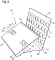
- the thus assembled carrier 34 is in the Figures 3 and 4 shown.
- a product 35 in small pieces can be inserted into each opening 3 of the top wall 2, so that it protrudes upwards over the top of the top wall 2 and can be easily grasped. This is only shown on the basis of a single product 35 used.
- the ready-made carrier 34 Before inserting small-sized products 35, the ready-made carrier 34 can be folded flat around the side fold lines 24, 26, 28, 29, 31, 32 so that the top wall 2 lies flat on the intermediate floor 7 and the intermediate floor 7 lies flat on the bottom wall 4.
- the first and the second support straps 13, 22, 23 are also pivoted into a horizontal orientation.
- a multiplicity of carriers 34 folded flat can be stored and transported in stacks. Before inserting products, the carriers 34 are erected so that they can accommodate the in Figures 3 and 4 Accept the configuration shown. To erect the carrier 34, the third side flap 30 and the fourth side flap 33 can be pressed from the outside in opposite directions.
- the first and second support devices 10, 11 prevent deformation of the carrier 34 so that the small-sized products 35 cannot escape from the openings 3.
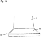
- the carrier 34 equipped with small-piece products 35 is inserted into the receptacle of a folding box 36 which, in the example, is designed as a hollow-wall folding box. A cushioning paper is then applied to the top of the small-piece products 35.
- the lid 37 which is designed as a hinged lid, is folded shut and closed by inserting a locking tab 38 into a slot 40 provided for this purpose in a front side wall 39 of the folding box 36.
- the packaging can still be wrapped in cellophane or plastic film.
- the cut 1 of Fig. 6 differs from the cut of Fig. 1 in particular in that the top wall 2 has uniform support tabs 41 and connecting tabs 16 in some openings 3.
- the uniform support flaps 41 comprise a first support flap 13, which is hinged to the edge of an opening 3 via a fold line 12 parallel to the side fold lines. Furthermore, they comprise a second support bracket 22, which is wider in comparison and which is connected in one piece to the first support bracket 13.
- the connecting tab 16 is connected to the second support tab 22 via a further fold line 15 which is aligned parallel to the fold line 12.
- the intermediate floor 7 comprises several further cutouts 42, the contour of which essentially corresponds to the contour of the uniform support bracket 41 and the connecting bracket 16.
- a punching line of the punching 42 parallel to the folding line 12 there is a further recess 43 in the middle, the width of which approximately corresponds to the width of the first support tab 13.
- the further blank 1 is folded like the blank 1 described above during assembly and is glued to one another at the side flaps 25, 27, 30, 33.
- the top wall 2 is folded over the intermediate floor 7, the first 13 and second support tabs 13, 22 and the connecting tabs 16 are each aligned with a further cutout 42 in the intermediate floor 7.
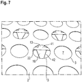
- the connecting straps 16 are glued to the bottom wall 4. This state is in Fig. 7 shown.
- Fig. 8 When erecting, the first support flap 13 is pivoted downwards around the fold line 12 and the second support flap 22, which is connected to it in one piece, is pivoted upwards around the further fold line 15. In the process, the intermediate floor 7 is raised and the second support bracket 22 pivots into the widened area of the cutout 42. According to Fig. 9 is slightly over 90 ° when erecting the carrier 34 pivoted out to break the fibers in the side fold lines 24, 26, 28, 29, 31, 32.
- Fig. 10 shows the carrier 34 in the upright position, in which the first support tab 13 engages in the further recess 43 and the edge areas of the wider second support tab 22 reach under the intermediate floor 7 next to the further recess 43.
- Pralines 35 are inserted into the carrier 34 so that they are supported at the bottom on the intermediate floor 7 and are guided approximately in the middle at the edges of the openings 3 in the top wall 2. They protrude from the top wall 2 with an upper part.
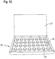
- Fig. 12 the carrier 34 with the chocolates 35 is inserted into a hollow-walled folding box 36.
- a cushioning paper 44 is placed on the chocolates 35 in the folding box 36.
- the folding box 36 can be closed by closing the lid 37 and fixing it in place.
Landscapes
- Engineering & Computer Science (AREA)
- Mechanical Engineering (AREA)
- Cartons (AREA)
Applications Claiming Priority (1)
| Application Number | Priority Date | Filing Date | Title |
|---|---|---|---|
| DE202019101008.8U DE202019101008U1 (de) | 2019-02-21 | 2019-02-21 | Träger aus faltbarem Flachmaterial für vorzugsweise kleinstückige Produkte |
Publications (1)
| Publication Number | Publication Date |
|---|---|
| EP3699110A1 true EP3699110A1 (fr) | 2020-08-26 |
Family
ID=69582002
Family Applications (1)
| Application Number | Title | Priority Date | Filing Date |
|---|---|---|---|
| EP20157087.6A Withdrawn EP3699110A1 (fr) | 2019-02-21 | 2020-02-13 | Support d'un matériau plat pliable pour des produits, de préférence, en petites pièces |
Country Status (2)
| Country | Link |
|---|---|
| EP (1) | EP3699110A1 (fr) |
| DE (1) | DE202019101008U1 (fr) |
Citations (2)
| Publication number | Priority date | Publication date | Assignee | Title |
|---|---|---|---|---|
| EP0269761A1 (fr) * | 1986-12-02 | 1988-06-08 | MONCARTONS S.p.A. | Récipient de présentation avec languettes d'assemblage |
| EP0441102A1 (fr) * | 1990-01-10 | 1991-08-14 | CARTOTECNICA CHIERESE S.p.A. | Plaque en carton perforée, destinée à contenir et à exhiber des bonbons et produits analogues |
-
2019
- 2019-02-21 DE DE202019101008.8U patent/DE202019101008U1/de active Active
-
2020
- 2020-02-13 EP EP20157087.6A patent/EP3699110A1/fr not_active Withdrawn
Patent Citations (2)
| Publication number | Priority date | Publication date | Assignee | Title |
|---|---|---|---|---|
| EP0269761A1 (fr) * | 1986-12-02 | 1988-06-08 | MONCARTONS S.p.A. | Récipient de présentation avec languettes d'assemblage |
| EP0441102A1 (fr) * | 1990-01-10 | 1991-08-14 | CARTOTECNICA CHIERESE S.p.A. | Plaque en carton perforée, destinée à contenir et à exhiber des bonbons et produits analogues |
Also Published As
| Publication number | Publication date |
|---|---|
| DE202019101008U1 (de) | 2020-05-25 |
Similar Documents
| Publication | Publication Date | Title |
|---|---|---|
| EP3871989B1 (fr) | Support en forme de coque en carton, carton gaufré ou estampé ou tout autre matière plane pliable | |
| EP1971526B1 (fr) | Dispositif constitue d'un materiau plat repliable destine a former des casiers de reception de recipients, flan pour le dispositif et emballage | |
| EP0976660A1 (fr) | Emballage pour un groupe d'articles et procédé de fabrication | |
| EP3699110A1 (fr) | Support d'un matériau plat pliable pour des produits, de préférence, en petites pièces | |
| DE3909898C2 (fr) | ||
| DE10240346B4 (de) | Verkaufsverpackung und Zuschnitt hierfür | |
| AT522769B1 (de) | Faltkiste | |
| DE4311568A1 (de) | Verpackung für stabförmige Gegenstände wie Zigaretten und Zuschnitt zum Herstellen der Verpackung | |
| EP1371567A2 (fr) | Enveloppe d'emballage | |
| EP2008936A1 (fr) | Cageots en carton à partir d'une section plane, section et aliment emballé | |
| DE2102431A1 (de) | Tray zur Verpackung von Waren in schrumpfbaren Folien sowie Verfahren und Vorrichtung zu deren Herstellung | |
| CH537321A (de) | Verpackung, insbesondere für Kekse | |
| DE19842619A1 (de) | Im wesentlichen quaderförmiger Behälter zur Aufnahme einer Mehrzahl von Gegenständen | |
| DE102014011624B4 (de) | Verpackung und Zuschnitt dafür | |
| DE29905401U1 (de) | Teilbare Steige | |
| EP3597553B1 (fr) | Garniture d'emballage et procédé de formation d'une garniture d'emballage | |
| DE102008035528A1 (de) | Schachtel zum Aufnehmen von Schalen mit Inhalt | |
| DE102008029217B4 (de) | Trayverpackung, insbesondere für schwere Produkte | |
| EP4509418A1 (fr) | Unité d'emballage avec élément intérieur et arrête pour support de produits | |
| DE102022212241A1 (de) | Verpackung für stückiges Packgut | |
| EP4091951A1 (fr) | Gobelet pliant | |
| AT18340U1 (de) | Bechersteige | |
| DE2818888A1 (de) | Verpackungsschale zur verpackung von flaschen in kisten | |
| EP3858752A1 (fr) | Emballage | |
| DE9109857U1 (de) | Verpackung aus faltbarem Material |
Legal Events
| Date | Code | Title | Description |
|---|---|---|---|
| PUAI | Public reference made under article 153(3) epc to a published international application that has entered the european phase |
Free format text: ORIGINAL CODE: 0009012 |
|
| STAA | Information on the status of an ep patent application or granted ep patent |
Free format text: STATUS: THE APPLICATION HAS BEEN PUBLISHED |
|
| AK | Designated contracting states |
Kind code of ref document: A1 Designated state(s): AL AT BE BG CH CY CZ DE DK EE ES FI FR GB GR HR HU IE IS IT LI LT LU LV MC MK MT NL NO PL PT RO RS SE SI SK SM TR |
|
| AX | Request for extension of the european patent |
Extension state: BA ME |
|
| RAP1 | Party data changed (applicant data changed or rights of an application transferred) |
Owner name: AR PACKAGING GMBH |
|
| STAA | Information on the status of an ep patent application or granted ep patent |
Free format text: STATUS: REQUEST FOR EXAMINATION WAS MADE |
|
| 17P | Request for examination filed |
Effective date: 20210217 |
|
| RBV | Designated contracting states (corrected) |
Designated state(s): AL AT BE BG CH CY CZ DE DK EE ES FI FR GB GR HR HU IE IS IT LI LT LU LV MC MK MT NL NO PL PT RO RS SE SI SK SM TR |
|
| STAA | Information on the status of an ep patent application or granted ep patent |
Free format text: STATUS: EXAMINATION IS IN PROGRESS |
|
| 17Q | First examination report despatched |
Effective date: 20230221 |
|
| STAA | Information on the status of an ep patent application or granted ep patent |
Free format text: STATUS: THE APPLICATION IS DEEMED TO BE WITHDRAWN |
|
| 18D | Application deemed to be withdrawn |
Effective date: 20250902 |