EP3699343B1 - Procédé et système de surveillance de la production d'une machine à tricoter pourvue d'une pluralité de dispositifs d'alimentation en fil - Google Patents
Procédé et système de surveillance de la production d'une machine à tricoter pourvue d'une pluralité de dispositifs d'alimentation en fil Download PDFInfo
- Publication number
- EP3699343B1 EP3699343B1 EP20156279.0A EP20156279A EP3699343B1 EP 3699343 B1 EP3699343 B1 EP 3699343B1 EP 20156279 A EP20156279 A EP 20156279A EP 3699343 B1 EP3699343 B1 EP 3699343B1
- Authority
- EP
- European Patent Office
- Prior art keywords
- signal
- thread delivery
- monitoring
- knitting machine
- machine
- Prior art date
- Legal status (The legal status is an assumption and is not a legal conclusion. Google has not performed a legal analysis and makes no representation as to the accuracy of the status listed.)
- Active
Links
Images


Classifications
-
- D—TEXTILES; PAPER
- D04—BRAIDING; LACE-MAKING; KNITTING; TRIMMINGS; NON-WOVEN FABRICS
- D04B—KNITTING
- D04B15/00—Details of, or auxiliary devices incorporated in, weft knitting machines, restricted to machines of this kind
- D04B15/94—Driving-gear not otherwise provided for
- D04B15/99—Driving-gear not otherwise provided for electrically controlled
-
- D—TEXTILES; PAPER
- D04—BRAIDING; LACE-MAKING; KNITTING; TRIMMINGS; NON-WOVEN FABRICS
- D04B—KNITTING
- D04B35/00—Details of, or auxiliary devices incorporated in, knitting machines, not otherwise provided for
- D04B35/10—Indicating, warning, or safety devices, e.g. stop motions
- D04B35/14—Indicating, warning, or safety devices, e.g. stop motions responsive to thread breakage
Definitions
- the invention relates to a method and a system with thread feed devices for monitoring the production of a knitting machine.
- the thread delivery of the thread feeding devices is monitored with a monitoring device, e.g. B. with a running monitor or an optical sensor, and the knitting machine is stopped if there is no thread delivery.
- a monitoring device may also indicate an error when the knitting machine is at a standstill or when individual threads are moved manually by the operating personnel.
- an electronic device for monitoring several running threads on a textile machine has a drive device common to all thread running points (work stations).
- a running monitor is assigned to each thread to generate signals indicating thread breakage.
- the outputs of the running monitors are connected to a disconnection device via a common line.
- the electronic device has a circuit for generating a control signal within the interval in which the drive device is switched on.
- a display device with a memory element and a display element connected to this for continuous display of a thread breakage and a switching element which causes a signal from the movement sensor indicating a thread break to only set the memory element for the duration of the control signal are provided for each movement monitor.
- the monitoring device only triggers a shutdown when the control signal indicates that the machine is running.
- the control signal is generated from the motor control circuit of the common drive device.
- a method for determining the stopping of the thread delivery from a weft thread feeding device or from a positive thread feeding device to a textile machine is from US Pat EP 3 269 857 A1 known.
- the thread feeding device is provided with a monitoring device, namely with a sensor which is designed to generate delivery pulses which indicate the unwinding of the thread.
- position pulses are used by the machine, which indicate the operating position of the textile machine.
- a stop signal is generated when the number of position pulses since the last delivery pulse exceeds a threshold value.
- the EP 2 857 567 A1 describes a method for monitoring the production of a knitting machine with several thread feeding devices, each of which has a sensor device for generating a sensor signal and a control unit for evaluating the sensor signal.
- the knitting machine is also provided with a control unit for the yarn feeders and a communication link to which the yarn feeders, the control unit and the machine control are connected.
- the control units evaluate the sensor signals as a function of a clock signal generated by the control unit and, if necessary, generate a stop signal.
- the clock signal is generated by the control unit from sensor signals from a plurality of storage thread delivery devices and made available to the control units of the thread delivery devices via the communication link.
- the object of the invention is to develop a method and a system with thread feeding devices for monitoring the production of a knitting machine, in which a signal that indicates whether the knitting machine is running is generated independently of the knitting machine.
- the thread delivery of each thread feeding device is monitored by a monitoring device and, if necessary, a stop signal for the knitting machine is sent via the monitoring connection. It is used by a machine running signal to detect whether the knitting machine is in operation.
- a sensor unit of the monitoring device For each yarn feeding device, a sensor unit of the monitoring device generates a sensor signal which is checked for a stop condition by a control unit of the monitoring device. If necessary, a stop signal is generated when the operation of the knitting machine is recognized with the aid of the machine running signal, i. H. when the machine running signal indicates the operation of the knitting machine.
- the machine running signal is generated by the control units of at least two yarn feeding devices with the aid of the sensor signals.
- I. E. Sensor signals are used, if necessary, to generate the machine running signal.
- Via the monitoring connection between the A monitoring signal is sent to the knitting machine and the parallel-connected control units of the yarn feeders, which contains both the machine running signal and, if necessary, the stop signal.
- the monitoring signal is an alternating voltage signal, the machine running signal being applied as half-waves and possibly a stop signal as the other half-waves.
- the machine running signal is generated with the positive half-waves and the stop signal with the negative half-waves of the AC voltage signal.
- the thread feeding devices are divided into a master thread feeding device and at least two groups of thread feeding devices.
- a first half-wave of the machine running signal is switched on by the master yarn feeder.
- a subsequent half-wave of the machine running signal is switched on by thread feed devices of each group each time the thread is delivered.
- the operation of the knitting machine is recognized by the control units of the monitoring devices of the thread feeders on the basis of the machine running signal if a half-wave has been switched on by the master thread feeder and by all groups within the control interval; ie when all groups have reported.
- the master thread feeder is also assigned to the first group. At the start of the control interval, a first half-wave and then a second half-wave of the machine running signal for the first group are switched on by the master yarn feeder.
- control interval is 80 ms to 300 ms or more.
- the control interval is in particular 80 ms to 120 ms.
- the sensor signal is in each case formed by an optical sensor device of the sensor unit, which is arranged on the yarn feeder.
- a system for monitoring the production of a knitting machine is provided with several thread feeders and a monitoring connection with which the thread feeders and the knitting machine are connected.
- Each thread feed device has a monitoring device for monitoring the thread delivery and, if necessary, for sending a stop signal for the knitting machine via the monitoring connection.
- the system is designed to use a machine running signal to detect whether the knitting machine is in operation.
- the monitoring device of each thread feeding device comprises a sensor unit for generating a sensor signal and a control unit for checking the sensor signal for a stop condition and possibly for generating a stop signal when the machine running signal indicates the operation of the knitting machine.
- the control units of at least two yarn feeding devices are designed to generate the machine running signal with the aid of the sensor signals.
- the monitoring connection (communication connection) is designed between the knitting machine and the to send a monitoring signal to the control units of the yarn feeding devices connected in parallel, which signal contains both the machine running signal and, if necessary, a stop signal.
- the monitoring connection is designed to send an AC voltage signal as a monitoring signal, one half-wave of which is formed by the machine running signal and the other half-wave of which is possibly formed by a stop signal.
- one of the yarn feeding devices is designed as a master yarn feeding device, the remaining yarn feeding devices being subdivided into at least two groups of yarn feeding devices.
- the master thread feeder is designed to switch on a first half-wave of the machine running signal within a control interval, and the thread feeders of each group are designed to switch on a subsequent half-wave of the machine running signal each time the thread is delivered.
- the control units of the sensor units are designed to recognize the operation of the knitting machine on the basis of the machine running signal when a half-wave has been switched on by the master thread feeder and by all groups within the control interval.
- the master yarn feeder is designed to switch on a first half-wave of the machine running signal at the start of the control interval and then a second half-wave for the first group.
- each sensor unit has an optical sensor device which is arranged on the thread feeding device and which is designed to generate the sensor signal.
- an optical sensor device is arranged on the outgoing thread of the thread feeding device.
- a system according to the invention with several thread delivery devices is designed for the delivery of threads to a knitting machine.
- the knitting machine is a circular knitting machine or a flat knitting machine or a knitting machine or a similar machine.
- a system for monitoring the production of a knitting machine has several thread feed devices 1, one of which is shown schematically in FIG Figure 1 is shown.
- the yarn feeder 1 shown is a storage yarn feeder. It comprises a housing 2, a storage device 3 on which a thread F can be wound and from which the thread F can be pulled off, a braking device with a braking body 5 and with an adjusting unit 6.
- Each thread feeding device 1 comprises a monitoring device U for monitoring the thread delivery and, if necessary, for sending a stop signal for the knitting machine.
- the monitoring device U comprises a sensor unit 7 for generating a sensor signal and a control unit 8 for checking the sensor signal for a stop condition and, if necessary, for generating a stop signal.
- the sensor unit 7 has an optical sensor device which is arranged on the yarn feeding device 1.
- the sensor device is designed as a withdrawal sensor which is arranged in the area of a withdrawal end of the storage device 3.
- the sensor unit 7 has a transmitter 9 and a receiver 10. It generates a sensor signal with withdrawal pulses I, a withdrawal pulse I being generated when a yarn turn is withdrawn from the storage device 3.
- the system is designed to generate a machine running signal by means of which it is recognized whether the knitting machine is in operation.
- the control unit 8 of the thread feeding devices 1 is each designed to check the sensor signal, specifically when the operation of the knitting machine is recognized with the aid of the machine running signal. I. E. the control unit 8 checks whether the sensor signal indicates at least one withdrawal pulse I when the knitting machine is running.
- the system shown has several thread feed devices 1 and a monitoring connection.
- the knitting machine and the thread feeding devices 1 are connected to the monitoring connection.
- the control units 8 of the yarn feeders 1 are connected in parallel.
- the monitoring connection is designed to send a monitoring signal between the knitting machine and the control units 8 of the thread feeding devices 1. It is designed in particular to send an AC voltage signal as a monitoring signal.
- the monitoring connection is designed as a communication connection with four lines L1 to L4.
- a three-phase current of 42 volts with a frequency of 50 Hz is applied to the three lines L1 to L3.
- d. H. Line L4 is used to transmit the monitoring signal in the form of an AC voltage signal.
- the control units 8 are designed to generate the machine running signal with the aid of the sensor signals.
- the control units 8 are designed to check the sensor signals for draw-off pulses I independently of information from the knitting machine and to generate a machine running signal if draw-off pulses I are present.
- the monitoring connection is designed to send the monitoring signal between the knitting machine and the control units 8 of the yarn feeding devices 1 connected in parallel.
- the monitoring signal contains both the machine running signal and the stop signal.
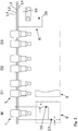
- the system in this example comprises a yarn feeder 1 designed as a master yarn feeder M, at least one yarn feeder 1 from a first group G1, at least one yarn feeder 1 from a second group G2 and at least one yarn feeder 1 from a third group G3.
- Each control unit 8 of the yarn feeder 1 comprises a control unit (not shown separately in the drawing), a diode D1 and a switch S1 for the negative half-wave of the alternating voltage signal and a diode D2 and a switch S2 for the positive half-wave of the alternating voltage signal.
- the monitoring connection is designed to send an alternating voltage signal whose positive half-waves generate a machine running signal and whose negative half-waves may generate a stop signal for the knitting machine.
- Figure 2 also shows a relay unit R of the knitting machine with a relay S3 and a diode D3.
- the diode D3 is acted upon, which leads to the actuation of the relay S3 and thus to the switching off of the knitting machine.
- Figure 3 shows a monitoring signal with the half-waves of the master yarn feeder M and each of a yarn feeder 1 of the groups G1, G2 and G3.
- the master thread feeder M is designed to switch on a first half-wave within a control interval when withdrawal pulses I are present by the control unit of its control unit 8 via switch S1, i.e. H. to deliver a start pulse of the machine run signal. This is used for synchronization.
- the thread feeding devices 1 of each group G1, G2 and G3 are designed to be activated by the control units of their control units 8 via the switches S1, in each case during thread delivery, i.e. H. when trigger pulses I are present, one of the following half-waves of the machine running signal is switched on.
- the control units 8 are designed to recognize a machine running signal when all groups G1, G2 and G3 have reported yarn delivery within the control interval started by the master yarn feeder M.
- the master yarn feeder M is also the yarn feeder 1 of the first group G1.
- Figure 4 shows a flow diagram of a control unit 8 of a yarn feeding device 1.
- control unit 8 specifically the control unit of the control unit 8, checks each thread feeding device 1 to determine whether the machine running signal is present. To this end, the control unit 8 checks whether all positive half-waves M, G1, G2, and G3 are applied to the monitoring signal.
- control unit of the control unit 8 checks whether trigger pulses I are present.
- control unit 8 specifically the control unit, generates a stop signal.
- switch S1 is actuated by the control unit.
- the stop signal is sent to the relay unit R of the knitting machine via the other (lower) half-wave and the knitting machine is stopped.
- control unit 8 checks whether withdrawal pulses I are present.
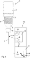
- Figure 5 shows an alternative to the monitoring device in which the sensor unit 70 of the monitoring device U, which is also designed as an optical sensor device, is arranged on the thread F at the outlet of the thread feeding device 1.
Landscapes
- Engineering & Computer Science (AREA)
- Textile Engineering (AREA)
- Knitting Machines (AREA)
Claims (10)
- Procédé pour surveiller la production d'une machine à tricoter comportant plusieurs fournisseurs de fil (1) et une liaison de surveillance, avec laquelle les fournisseurs de fil (1) et la machine à tricoter sont reliés, dans lequel l'alimentation en fil de chaque fournisseur de fil (1) est surveillée par un dispositif de surveillance (U) et, le cas échéant, un signal d'arrêt pour la machine à tricoter est envoyé par l'intermédiaire de la liaison de surveillance,dans lequel un signal de fonctionnement de machine est utilisé pour détecter si la machine à tricoter est en fonctionnement,dans lequel un signal de capteur est généré pour chaque fournisseur de fil (1) par une unité de capteur (7) du dispositif de surveillance (U),dans lequel le signal de capteur est vérifié pour une condition d'arrêt par une unité de commande (8) du dispositif de surveillance (U), etle cas échéant, un signal d'arrêt est généré lorsque le fonctionnement de la machine à tricoter est détecté à l'aide du signal de fonctionnement de machine, caractérisé en ce que les fournisseurs de fil (1) sont reliés à une unité de relais (R) de la machine à tricoter par l'intermédiaire de la liaison de surveillance, etdans lequel le signal de fonctionnement de machine est généré par les unités de commande (8) d'au moins deux fournisseurs de fil (1) à l'aide des signaux de capteur, et un signal de surveillance est envoyé par l'intermédiaire de la liaison de surveillance entre l'unité de relais (R) de la machine à tricoter et les unités de commande (8) connectées en parallèle des fournisseurs de fil (1), qui contient aussi bien le signal de fonctionnement de machine que, le cas échéant, le signal d'arrêt.
- Procédé selon la revendication 1, caractérisé en ce que le signal de surveillance est un signal de tension alternative, dans lequel le signal de fonctionnement de machine est connecté comme demi-ondes et, le cas échéant, un signal d'arrêt est appliqué comme les autres demi-ondes.
- Procédé selon la revendication 1 ou 2, caractérisé en ce que les fournisseurs de fil (1) sont divisés en un fournisseur de fil maître (M) et au moins deux groupes (G1, G2, ...) des fournisseurs de fil (1), dans lequel, au sein d'un intervalle de commande, une première demi-onde du signal de fonctionnement de machine est appliquée par le fournisseur de fil maître (M) et une seconde demi-onde du signal de fonctionnement de machine est appliquée par les fournisseurs de fil (1) de chaque groupe (G1, G2, ...), dans lequel le fonctionnement de la machine à tricoter est détecté par les unités de commande (8) à l'aide du signal de fonctionnement de machine lorsqu'une demi-onde a été appliquée respectivement par le fournisseur de fil maître (M) et par tous les groupes (G1, G2, ...) au sein de l'intervalle de commande.
- Procédé selon la revendication 3, caractérisé en ce que l'intervalle de commande est de 80 ms à 300 ms ou plus.
- Procédé selon la revendication 4, caractérisé en ce que l'intervalle de commande est de 80 ms à 120 ms.
- Procédé selon l'une quelconque des revendications 1 à 5, caractérisé en ce que le signal de capteur est respectivement formé par un dispositif de capteur optique de l'unité de capteur (7) qui est disposée sur le fournisseur de fil (1).
- Système pour surveiller la production d'une machine à tricoter avec plusieurs fournisseurs de fil (1) et avec une liaison de surveillance à laquelle les fournisseurs de fil (1) et la machine à tricoter sont reliés,dans lequel chaque fournisseur de fil (1) présente un dispositif de surveillance (U) pour surveiller l'alimentation en fil et, le cas échéant, pour envoyer un signal d'arrêt pour la machine à tricoter par l'intermédiaire de la liaison de surveillance, etdans lequel le système est réalisé pour utiliser un signal de fonctionnement de machine pour détecter si la machine à tricoter est en fonctionnement,dans lequel le dispositif de surveillance (U) de chaque fournisseur de fil (1) présente une unité de capteur (7) pour générer un signal de capteur et une unité de commande (8) pour vérifier le signal de capteur pour une condition d'arrêt et, le cas échéant, pour générer un signal d'arrêt lorsque le signal de fonctionnement de machine indique le fonctionnement de la machine à tricoter, caractérisé en ce que les fournisseurs de fil (1) sont reliés à une unité de relais (R) de la machine à tricoter par l'intermédiaire de la liaison de surveillance, et dans lequel les unités de commande (8) d'au moins deux fournisseurs de fil (1) sont réalisées pour générer le signal de fonctionnement de machine à l'aide des signaux de capteur, et la liaison de surveillance est réalisée pour envoyer un signal de surveillance entre l'unité de relais (R) de la machine à tricoter et les unités de commande (8) connectées en parallèle des fournisseurs de fil (1), qui contient aussi bien le signal de fonctionnement de machine que, le cas échéant, le signal d'arrêt.
- Système selon la revendication 7, caractérisé en ce que la liaison de surveillance est réalisée pour envoyer un signal de tension alternative comme signal de surveillance, dont une demi-onde est formée par le signal de fonctionnement de machine et dont l'autre demi-onde est formée, le cas échéant, par un signal d'arrêt.
- Système selon la revendication 8, caractérisé en ce qu'un des fournisseurs de fil (1) est réalisé comme un fournisseur de fil maître (M), dans lequel les fournisseurs de fil restants (1) sont divisés en au moins deux groupes (G1, G2, ...) des fournisseurs de fil (1), dans lequel le fournisseur de fil maître (M) est réalisé pour appliquer une première demi-onde du signal de fonctionnement de machine au sein d'un intervalle de commande,
et les fournisseurs de fil (1) de chaque groupe (G1, G2, ...) sont réalisés pour appliquer respectivement une demi-onde suivante du signal de fonctionnement de machine lors de l'alimentation en fil, dans lequel les unités de commande (8) des unités de détection (7) sont réalisées pour détecter le fonctionnement de la machine à tricoter sur la base du signal de fonctionnement de machine lorsqu'une demi-onde a été appliquée respectivement par le fournisseur de fil maître (M) et par tous les groupes (G1, G2, ...) au sein de l'intervalle de commande. - Système selon l'une quelconque des revendications 7 à 9, caractérisé en ce que l'unité de détection (7) présente respectivement un dispositif de détection optique qui est disposé sur le fournisseur de fil (1) et qui est réalisé pour générer le signal de détection.
Applications Claiming Priority (1)
| Application Number | Priority Date | Filing Date | Title |
|---|---|---|---|
| DE102019104681.5A DE102019104681B3 (de) | 2019-02-25 | 2019-02-25 | Verfahren und System mit Fadenliefergeräten zur Überwachung der Produktion einer Strickmaschine |
Publications (2)
| Publication Number | Publication Date |
|---|---|
| EP3699343A1 EP3699343A1 (fr) | 2020-08-26 |
| EP3699343B1 true EP3699343B1 (fr) | 2022-01-05 |
Family
ID=69528672
Family Applications (1)
| Application Number | Title | Priority Date | Filing Date |
|---|---|---|---|
| EP20156279.0A Active EP3699343B1 (fr) | 2019-02-25 | 2020-02-10 | Procédé et système de surveillance de la production d'une machine à tricoter pourvue d'une pluralité de dispositifs d'alimentation en fil |
Country Status (4)
| Country | Link |
|---|---|
| EP (1) | EP3699343B1 (fr) |
| CN (1) | CN111607891B (fr) |
| DE (1) | DE102019104681B3 (fr) |
| TW (1) | TWI760670B (fr) |
Families Citing this family (1)
| Publication number | Priority date | Publication date | Assignee | Title |
|---|---|---|---|---|
| CN118771098A (zh) * | 2023-04-06 | 2024-10-15 | 爱吉尔电子股份公司 | 用于在纺织工艺中同时配置多个电子控制的纱线供给器的设置方法 |
Family Cites Families (12)
| Publication number | Priority date | Publication date | Assignee | Title |
|---|---|---|---|---|
| CH629456A5 (de) | 1978-06-19 | 1982-04-30 | Loepfe Ag Geb | Elektronische einrichtung zur ueberwachung einer mehrzahl laufender faeden an einer textilmaschine. |
| DE4105450A1 (de) * | 1991-02-21 | 1992-08-27 | Frei Gmbh & Co Geb | Schaltungsanordnung zum anschluss einer vielzahl von sensoren an eine zentrale steuereinheit |
| IT1275465B (it) * | 1995-07-03 | 1997-08-07 | Tiziano Barea | Dispositivo di controllo dell'alimentazione di una pluralita' di fili o filati ad una macchina tessile avente mezzi sensori codificati e metodo per il suo controllo |
| DE10112795A1 (de) * | 2001-03-16 | 2002-09-26 | Iro Ab | Verfahren zur Produktionsüberwachungs/Einstellung einer Strickmaschine, und Produktionsüberwachungs/Einstellungs-Vorrichtung |
| DE10228794A1 (de) * | 2002-06-27 | 2004-01-15 | Iropa Ag | Fadenverarbeitendes System und Verfahren zum Steuern und/oder Überwachen des Systems |
| CN2671223Y (zh) * | 2003-12-23 | 2005-01-12 | 中国科学院安徽光学精密机械研究所 | 无主变压器式激光脉冲电源 |
| WO2009059438A1 (fr) * | 2007-11-06 | 2009-05-14 | Rotorcraft Ag | Métier à tricoter et procédé de fabrication de tricots à partir de mèches de préparation |
| DE102013110988B4 (de) * | 2013-10-02 | 2019-08-29 | Memminger-Iro Gmbh | Verfahren und Vorrichtung zur Überwachung der Produktion einer Strickmaschine sowie Strickmaschine |
| CN104131410B (zh) * | 2014-08-14 | 2016-06-01 | 江南大学 | 经编机无线控制器和无线控制方法 |
| WO2016091286A1 (fr) * | 2014-12-09 | 2016-06-16 | Memminger-Iro Gmbh | Procédé et dispositif de surveillance de machine à tricoter |
| DE102015104903B3 (de) * | 2015-03-30 | 2016-06-16 | Memminger-Iro Gmbh | Verfahren und Vorrichtung zur Überwachung der Produktion einer Strickmaschine sowie Strickmaschine |
| IT201600074062A1 (it) | 2016-07-15 | 2018-01-15 | Lgl Electronics Spa | Metodo per il controllo dello svolgimento di filato da un alimentatore di trama |
-
2019
- 2019-02-25 DE DE102019104681.5A patent/DE102019104681B3/de not_active Expired - Fee Related
- 2019-12-23 TW TW108147164A patent/TWI760670B/zh active
-
2020
- 2020-02-10 EP EP20156279.0A patent/EP3699343B1/fr active Active
- 2020-02-25 CN CN202010115167.8A patent/CN111607891B/zh active Active
Also Published As
| Publication number | Publication date |
|---|---|
| TWI760670B (zh) | 2022-04-11 |
| TW202031955A (zh) | 2020-09-01 |
| CN111607891A (zh) | 2020-09-01 |
| DE102019104681B3 (de) | 2020-04-23 |
| CN111607891B (zh) | 2022-02-22 |
| EP3699343A1 (fr) | 2020-08-26 |
Similar Documents
| Publication | Publication Date | Title |
|---|---|---|
| DE2153605C2 (de) | Fernüberwachungssystem für ein PCM- Übertragungssystem | |
| EP1269274B2 (fr) | Interrupteur de securite et procede pour ajuster un mode de fonctionnement pour interrupteur de securite | |
| EP1638880B2 (fr) | Systeme de securite d'une installation d'ascenseur | |
| DE4319485C2 (de) | Steuervorrichtung für eine Spinnereimaschine | |
| EP1493064A2 (fr) | Appareil de coupure, protegee contre les erreurs, d'un consommateur electrique, notamment dans les installations de production industrielle | |
| EP0389849A2 (fr) | Système de commande pour une machine textile | |
| CH629456A5 (de) | Elektronische einrichtung zur ueberwachung einer mehrzahl laufender faeden an einer textilmaschine. | |
| DE19907684B4 (de) | Textilmaschine mit Prozessoren an den Arbeitsstellen | |
| EP0279168A2 (fr) | Circuit pour l'alimentation de courant d'une pluralité de consommateurs | |
| EP0322698A1 (fr) | Méthode pour la transmission d'informations | |
| EP3699343B1 (fr) | Procédé et système de surveillance de la production d'une machine à tricoter pourvue d'une pluralité de dispositifs d'alimentation en fil | |
| EP3645772A1 (fr) | Dispositif de filage par fusion | |
| DE102010022560B4 (de) | Verfahren zum Betreiben einer Gefahrenmeldeanlage | |
| EP0421471A1 (fr) | Méthode de communication pour un dispositif de commande constitué par une unité centrale et des unités périphériques | |
| EP2917795A1 (fr) | Procédé d'identification de la position de montage relative des modules utilisés dans un système électronique modulaire | |
| EP2846462A1 (fr) | Procédé destiné à la surveillance d'une alimentation en courant | |
| DE4327848C2 (de) | Steuereinrichtung für eine Druckmaschine | |
| WO1988005570A1 (fr) | Procede et dispositif de surveillance d'organes de commande terminaux commandes par un ordinateur | |
| DE19547068B4 (de) | Serviceeinrichtung an einer Spinnmaschine | |
| EP2645887A1 (fr) | Dispositif et procédé de transfert d'articles en forme de barre de l'industrie de traitement du tabac | |
| EP3075690B1 (fr) | Procede et dispositif de surveillance de la production d'une machine a tricoter et machine a tricoter | |
| EP0809361B1 (fr) | Dispositif électronique de commutation et circuit pour la surveillance d'une installation technique | |
| DE2519221C2 (de) | Verfahren und Vorrichtung zum Fühlen von Fadenbrüchen an Spinn- oder Zwirnmaschinen | |
| EP2746892A1 (fr) | Installation automatisée et procédé de synchronisation d'une installation automatisée | |
| CH618476A5 (fr) |
Legal Events
| Date | Code | Title | Description |
|---|---|---|---|
| PUAI | Public reference made under article 153(3) epc to a published international application that has entered the european phase |
Free format text: ORIGINAL CODE: 0009012 |
|
| STAA | Information on the status of an ep patent application or granted ep patent |
Free format text: STATUS: THE APPLICATION HAS BEEN PUBLISHED |
|
| AK | Designated contracting states |
Kind code of ref document: A1 Designated state(s): AL AT BE BG CH CY CZ DE DK EE ES FI FR GB GR HR HU IE IS IT LI LT LU LV MC MK MT NL NO PL PT RO RS SE SI SK SM TR |
|
| AX | Request for extension of the european patent |
Extension state: BA ME |
|
| STAA | Information on the status of an ep patent application or granted ep patent |
Free format text: STATUS: REQUEST FOR EXAMINATION WAS MADE |
|
| 17P | Request for examination filed |
Effective date: 20210222 |
|
| RBV | Designated contracting states (corrected) |
Designated state(s): AL AT BE BG CH CY CZ DE DK EE ES FI FR GB GR HR HU IE IS IT LI LT LU LV MC MK MT NL NO PL PT RO RS SE SI SK SM TR |
|
| GRAP | Despatch of communication of intention to grant a patent |
Free format text: ORIGINAL CODE: EPIDOSNIGR1 |
|
| STAA | Information on the status of an ep patent application or granted ep patent |
Free format text: STATUS: GRANT OF PATENT IS INTENDED |
|
| INTG | Intention to grant announced |
Effective date: 20211021 |
|
| GRAS | Grant fee paid |
Free format text: ORIGINAL CODE: EPIDOSNIGR3 |
|
| GRAA | (expected) grant |
Free format text: ORIGINAL CODE: 0009210 |
|
| STAA | Information on the status of an ep patent application or granted ep patent |
Free format text: STATUS: THE PATENT HAS BEEN GRANTED |
|
| AK | Designated contracting states |
Kind code of ref document: B1 Designated state(s): AL AT BE BG CH CY CZ DE DK EE ES FI FR GB GR HR HU IE IS IT LI LT LU LV MC MK MT NL NO PL PT RO RS SE SI SK SM TR |
|
| REG | Reference to a national code |
Ref country code: GB Ref legal event code: FG4D Free format text: NOT ENGLISH |
|
| REG | Reference to a national code |
Ref country code: CH Ref legal event code: EP |
|
| REG | Reference to a national code |
Ref country code: AT Ref legal event code: REF Ref document number: 1460688 Country of ref document: AT Kind code of ref document: T Effective date: 20220115 |
|
| REG | Reference to a national code |
Ref country code: DE Ref legal event code: R096 Ref document number: 502020000511 Country of ref document: DE |
|
| REG | Reference to a national code |
Ref country code: IE Ref legal event code: FG4D Free format text: LANGUAGE OF EP DOCUMENT: GERMAN |
|
| REG | Reference to a national code |
Ref country code: LT Ref legal event code: MG9D |
|
| REG | Reference to a national code |
Ref country code: NL Ref legal event code: MP Effective date: 20220105 |
|
| PG25 | Lapsed in a contracting state [announced via postgrant information from national office to epo] |
Ref country code: NL Free format text: LAPSE BECAUSE OF FAILURE TO SUBMIT A TRANSLATION OF THE DESCRIPTION OR TO PAY THE FEE WITHIN THE PRESCRIBED TIME-LIMIT Effective date: 20220105 |
|
| PG25 | Lapsed in a contracting state [announced via postgrant information from national office to epo] |
Ref country code: SE Free format text: LAPSE BECAUSE OF FAILURE TO SUBMIT A TRANSLATION OF THE DESCRIPTION OR TO PAY THE FEE WITHIN THE PRESCRIBED TIME-LIMIT Effective date: 20220105 Ref country code: RS Free format text: LAPSE BECAUSE OF FAILURE TO SUBMIT A TRANSLATION OF THE DESCRIPTION OR TO PAY THE FEE WITHIN THE PRESCRIBED TIME-LIMIT Effective date: 20220105 Ref country code: PT Free format text: LAPSE BECAUSE OF FAILURE TO SUBMIT A TRANSLATION OF THE DESCRIPTION OR TO PAY THE FEE WITHIN THE PRESCRIBED TIME-LIMIT Effective date: 20220505 Ref country code: NO Free format text: LAPSE BECAUSE OF FAILURE TO SUBMIT A TRANSLATION OF THE DESCRIPTION OR TO PAY THE FEE WITHIN THE PRESCRIBED TIME-LIMIT Effective date: 20220405 Ref country code: LT Free format text: LAPSE BECAUSE OF FAILURE TO SUBMIT A TRANSLATION OF THE DESCRIPTION OR TO PAY THE FEE WITHIN THE PRESCRIBED TIME-LIMIT Effective date: 20220105 Ref country code: HR Free format text: LAPSE BECAUSE OF FAILURE TO SUBMIT A TRANSLATION OF THE DESCRIPTION OR TO PAY THE FEE WITHIN THE PRESCRIBED TIME-LIMIT Effective date: 20220105 Ref country code: ES Free format text: LAPSE BECAUSE OF FAILURE TO SUBMIT A TRANSLATION OF THE DESCRIPTION OR TO PAY THE FEE WITHIN THE PRESCRIBED TIME-LIMIT Effective date: 20220105 Ref country code: BG Free format text: LAPSE BECAUSE OF FAILURE TO SUBMIT A TRANSLATION OF THE DESCRIPTION OR TO PAY THE FEE WITHIN THE PRESCRIBED TIME-LIMIT Effective date: 20220405 |
|
| PG25 | Lapsed in a contracting state [announced via postgrant information from national office to epo] |
Ref country code: PL Free format text: LAPSE BECAUSE OF FAILURE TO SUBMIT A TRANSLATION OF THE DESCRIPTION OR TO PAY THE FEE WITHIN THE PRESCRIBED TIME-LIMIT Effective date: 20220105 Ref country code: LV Free format text: LAPSE BECAUSE OF FAILURE TO SUBMIT A TRANSLATION OF THE DESCRIPTION OR TO PAY THE FEE WITHIN THE PRESCRIBED TIME-LIMIT Effective date: 20220105 Ref country code: GR Free format text: LAPSE BECAUSE OF FAILURE TO SUBMIT A TRANSLATION OF THE DESCRIPTION OR TO PAY THE FEE WITHIN THE PRESCRIBED TIME-LIMIT Effective date: 20220406 Ref country code: FI Free format text: LAPSE BECAUSE OF FAILURE TO SUBMIT A TRANSLATION OF THE DESCRIPTION OR TO PAY THE FEE WITHIN THE PRESCRIBED TIME-LIMIT Effective date: 20220105 |
|
| PG25 | Lapsed in a contracting state [announced via postgrant information from national office to epo] |
Ref country code: IS Free format text: LAPSE BECAUSE OF FAILURE TO SUBMIT A TRANSLATION OF THE DESCRIPTION OR TO PAY THE FEE WITHIN THE PRESCRIBED TIME-LIMIT Effective date: 20220505 |
|
| REG | Reference to a national code |
Ref country code: DE Ref legal event code: R097 Ref document number: 502020000511 Country of ref document: DE |
|
| REG | Reference to a national code |
Ref country code: BE Ref legal event code: MM Effective date: 20220228 |
|
| PG25 | Lapsed in a contracting state [announced via postgrant information from national office to epo] |
Ref country code: SM Free format text: LAPSE BECAUSE OF FAILURE TO SUBMIT A TRANSLATION OF THE DESCRIPTION OR TO PAY THE FEE WITHIN THE PRESCRIBED TIME-LIMIT Effective date: 20220105 Ref country code: SK Free format text: LAPSE BECAUSE OF FAILURE TO SUBMIT A TRANSLATION OF THE DESCRIPTION OR TO PAY THE FEE WITHIN THE PRESCRIBED TIME-LIMIT Effective date: 20220105 Ref country code: RO Free format text: LAPSE BECAUSE OF FAILURE TO SUBMIT A TRANSLATION OF THE DESCRIPTION OR TO PAY THE FEE WITHIN THE PRESCRIBED TIME-LIMIT Effective date: 20220105 Ref country code: MC Free format text: LAPSE BECAUSE OF FAILURE TO SUBMIT A TRANSLATION OF THE DESCRIPTION OR TO PAY THE FEE WITHIN THE PRESCRIBED TIME-LIMIT Effective date: 20220105 Ref country code: LU Free format text: LAPSE BECAUSE OF NON-PAYMENT OF DUE FEES Effective date: 20220210 Ref country code: EE Free format text: LAPSE BECAUSE OF FAILURE TO SUBMIT A TRANSLATION OF THE DESCRIPTION OR TO PAY THE FEE WITHIN THE PRESCRIBED TIME-LIMIT Effective date: 20220105 Ref country code: DK Free format text: LAPSE BECAUSE OF FAILURE TO SUBMIT A TRANSLATION OF THE DESCRIPTION OR TO PAY THE FEE WITHIN THE PRESCRIBED TIME-LIMIT Effective date: 20220105 Ref country code: CZ Free format text: LAPSE BECAUSE OF FAILURE TO SUBMIT A TRANSLATION OF THE DESCRIPTION OR TO PAY THE FEE WITHIN THE PRESCRIBED TIME-LIMIT Effective date: 20220105 |
|
| PLBE | No opposition filed within time limit |
Free format text: ORIGINAL CODE: 0009261 |
|
| STAA | Information on the status of an ep patent application or granted ep patent |
Free format text: STATUS: NO OPPOSITION FILED WITHIN TIME LIMIT |
|
| PG25 | Lapsed in a contracting state [announced via postgrant information from national office to epo] |
Ref country code: AL Free format text: LAPSE BECAUSE OF FAILURE TO SUBMIT A TRANSLATION OF THE DESCRIPTION OR TO PAY THE FEE WITHIN THE PRESCRIBED TIME-LIMIT Effective date: 20220105 |
|
| 26N | No opposition filed |
Effective date: 20221006 |
|
| PG25 | Lapsed in a contracting state [announced via postgrant information from national office to epo] |
Ref country code: IE Free format text: LAPSE BECAUSE OF NON-PAYMENT OF DUE FEES Effective date: 20220210 Ref country code: FR Free format text: LAPSE BECAUSE OF NON-PAYMENT OF DUE FEES Effective date: 20220305 |
|
| PG25 | Lapsed in a contracting state [announced via postgrant information from national office to epo] |
Ref country code: SI Free format text: LAPSE BECAUSE OF FAILURE TO SUBMIT A TRANSLATION OF THE DESCRIPTION OR TO PAY THE FEE WITHIN THE PRESCRIBED TIME-LIMIT Effective date: 20220105 Ref country code: BE Free format text: LAPSE BECAUSE OF NON-PAYMENT OF DUE FEES Effective date: 20220228 |
|
| REG | Reference to a national code |
Ref country code: CH Ref legal event code: PL |
|
| PG25 | Lapsed in a contracting state [announced via postgrant information from national office to epo] |
Ref country code: LI Free format text: LAPSE BECAUSE OF NON-PAYMENT OF DUE FEES Effective date: 20230228 Ref country code: CH Free format text: LAPSE BECAUSE OF NON-PAYMENT OF DUE FEES Effective date: 20230228 |
|
| REG | Reference to a national code |
Ref country code: DE Ref legal event code: R082 Ref document number: 502020000511 Country of ref document: DE Representative=s name: PAUL & ALBRECHT PATENTANWAELTE PARTG MBB, DE |
|
| PG25 | Lapsed in a contracting state [announced via postgrant information from national office to epo] |
Ref country code: MK Free format text: LAPSE BECAUSE OF FAILURE TO SUBMIT A TRANSLATION OF THE DESCRIPTION OR TO PAY THE FEE WITHIN THE PRESCRIBED TIME-LIMIT Effective date: 20220105 Ref country code: CY Free format text: LAPSE BECAUSE OF FAILURE TO SUBMIT A TRANSLATION OF THE DESCRIPTION OR TO PAY THE FEE WITHIN THE PRESCRIBED TIME-LIMIT Effective date: 20220105 |
|
| PG25 | Lapsed in a contracting state [announced via postgrant information from national office to epo] |
Ref country code: HU Free format text: LAPSE BECAUSE OF FAILURE TO SUBMIT A TRANSLATION OF THE DESCRIPTION OR TO PAY THE FEE WITHIN THE PRESCRIBED TIME-LIMIT; INVALID AB INITIO Effective date: 20200210 |
|
| P01 | Opt-out of the competence of the unified patent court (upc) registered |
Effective date: 20240507 |
|
| PG25 | Lapsed in a contracting state [announced via postgrant information from national office to epo] |
Ref country code: MT Free format text: LAPSE BECAUSE OF FAILURE TO SUBMIT A TRANSLATION OF THE DESCRIPTION OR TO PAY THE FEE WITHIN THE PRESCRIBED TIME-LIMIT Effective date: 20220105 |
|
| GBPC | Gb: european patent ceased through non-payment of renewal fee |
Effective date: 20240210 |
|
| PG25 | Lapsed in a contracting state [announced via postgrant information from national office to epo] |
Ref country code: GB Free format text: LAPSE BECAUSE OF NON-PAYMENT OF DUE FEES Effective date: 20240210 |
|
| PG25 | Lapsed in a contracting state [announced via postgrant information from national office to epo] |
Ref country code: GB Free format text: LAPSE BECAUSE OF NON-PAYMENT OF DUE FEES Effective date: 20240210 |
|
| PGFP | Annual fee paid to national office [announced via postgrant information from national office to epo] |
Ref country code: AT Payment date: 20250417 Year of fee payment: 5 |
|
| PGFP | Annual fee paid to national office [announced via postgrant information from national office to epo] |
Ref country code: DE Payment date: 20260217 Year of fee payment: 7 |
|
| PG25 | Lapsed in a contracting state [announced via postgrant information from national office to epo] |
Ref country code: AT Free format text: LAPSE BECAUSE OF NON-PAYMENT OF DUE FEES Effective date: 20250210 |
|
| PGFP | Annual fee paid to national office [announced via postgrant information from national office to epo] |
Ref country code: IT Payment date: 20260227 Year of fee payment: 7 |
|
| REG | Reference to a national code |
Ref country code: AT Ref legal event code: MM01 Ref document number: 1460688 Country of ref document: AT Kind code of ref document: T Effective date: 20250210 |
|
| PGFP | Annual fee paid to national office [announced via postgrant information from national office to epo] |
Ref country code: TR Payment date: 20260205 Year of fee payment: 7 |