EP2746892A1 - Installation automatisée et procédé de synchronisation d'une installation automatisée - Google Patents
Installation automatisée et procédé de synchronisation d'une installation automatisée Download PDFInfo
- Publication number
- EP2746892A1 EP2746892A1 EP12008586.5A EP12008586A EP2746892A1 EP 2746892 A1 EP2746892 A1 EP 2746892A1 EP 12008586 A EP12008586 A EP 12008586A EP 2746892 A1 EP2746892 A1 EP 2746892A1
- Authority
- EP
- European Patent Office
- Prior art keywords
- time
- automated system
- signal network
- global
- change
- Prior art date
- Legal status (The legal status is an assumption and is not a legal conclusion. Google has not performed a legal analysis and makes no representation as to the accuracy of the status listed.)
- Granted
Links
Images
Classifications
-
- G—PHYSICS
- G06—COMPUTING OR CALCULATING; COUNTING
- G06F—ELECTRIC DIGITAL DATA PROCESSING
- G06F1/00—Details not covered by groups G06F3/00 - G06F13/00 and G06F21/00
- G06F1/04—Generating or distributing clock signals or signals derived directly therefrom
- G06F1/12—Synchronisation of different clock signals provided by a plurality of clock generators
-
- H—ELECTRICITY
- H04—ELECTRIC COMMUNICATION TECHNIQUE
- H04J—MULTIPLEX COMMUNICATION
- H04J3/00—Time-division multiplex systems
- H04J3/02—Details
- H04J3/06—Synchronising arrangements
- H04J3/0635—Clock or time synchronisation in a network
- H04J3/0638—Clock or time synchronisation among nodes; Internode synchronisation
- H04J3/0658—Clock or time synchronisation among packet nodes
Definitions
- the invention relates to an automated system and a method for synchronizing an automated system.
- Automated plant is understood in particular to mean a production line but also any other automation solution in the field of mechanical engineering.
- a method for time synchronization in a cyclic communication system is known.
- this one time absolute information is sent to all participants of the communication system and used as a reference for the calculation of a local time at each of the communication participants.
- the absolute time information is in the format "2000-04-01, 16:05:30, 123".
- the invention has for its object to provide a particularly suitable automated system and a particularly suitable method for synchronization of an automated system, which is relatively simple and independent.
- the automated system includes two electrical components that interact with each other.
- the automated system is, for example, a production line, a printing press or a CNC milling machine.
- automated automation covers all automation solutions in the field of mechanical engineering.
- automated assembly means any well-planned combination of spatially related machines or devices, with machines or devices being referred to as electrical components.
- the automated system can also form only a portion of another, larger system.
- the two electrical components cooperate, so in particular one of the two components is dependent on the other.
- the electrical components are in particular sensors and / or actuators, such as. B. an electric motor that drives in particular a belt conveyor or the like, or other machines, such as grippers.
- Each of the components has its own time counter and the components are interconnected by means of a signaling network. This is done z. B. by means of suitable data transmission cable or by radio.
- Process data is transferred cyclically via the signal network. In other words, there is a periodic exchange of data between the individual components by means of a cyclic transmission over the signal network.
- the signal network is preferably fieldbus or other bus system, suitably EtherCat.
- the electrical components are synchronized with one another.
- a common reference for the time counter of all components is used. Starting from this reference is by means of the time counter local timestamp of each electrical component determined.
- the elapsed time since the reference value is determined in each case and used as a local time stamp.
- the reference itself is a global time information, ie a time information that applies to the complete automated system or at least the part of the automated system that is synchronized.
- the time information is relative and therefore has only a reference to the automated system.
- the relative time information is essentially independent of events that have taken place outside of the automated system, have played or are not related to the automated system.
- the global, relative time information is, for example, the time of completion of a particular process, eg. As the production of the hundredth production piece, the time of replacement or repair of a particular part of the system or the like.
- the global relative time information is a state change.
- the reference value used is the time of a specific change in the state of the automated system.
- the global relative time information is not a time itself.
- the change of state is the beginning of an energization of the automated system or the time when the automated system is first put into operation.
- the state change of the automated plant affects each of the electrical components so that they receive a uniform reference.
- any existing transit time differences do not have to be considered.
- the change of state is a change of the automated system in an operating state.
- the components are synchronized based on the change in the operating state. Consequently, the time interval between the interaction of the electrical components and their synchronization based on the common reference is comparatively low, so that even with any existing deviation or inaccuracies of the time counter to each other synchronization is given at least for a certain time after the start of operation of the automated system ,
- the change to the operating mode from a standby mode in which there is already a supply of components of the automated system.
- an electrical voltage is already applied to the electrical components in standby mode.
- any existing capacitors or the like do not have to be charged, which on the one hand leads to a substantially immediate operational readiness of the automated system.
- substantially immediate registration of the relative global time information is enabled.
- a deviation of the reception and / or the processing of the relative, global time information in the individual electrical components is essentially not given but rather at the same time. If an EtherCAT standard is used as the signal network, the change from "preoperational" to "operational” is used as the change, but at least the one to "operational” when using fieldbuses.
- the state change itself is transmitted via the signal network.
- a message is transmitted via the signal network, which is received by the individual electrical components.
- the individual electrical components Upon receipt of this message, at least a portion of the electrical components of the automated change Plant the operating mode so that the automated plant is transferred to a new state.
- all electrical components draw the time of receipt of the message, which triggers a change in the state of the automated system, as a reference for synchronization. Due to the transmission of the state change via the signal network, no further registration of the state of the automated system by the electrical components themselves is necessary. Also, due to the use of the message changing and causing the state change, there is no time lag between the actual state change and the time taken as a reference, as is the case with the use of two or more messages and a latency caused thereby.
- the time counting begins by means of the time counters.
- a time counting takes place by means of the time counters before receiving the global, relative time information.
- the time counters are essentially continuously activated, even in the event of a possible change to standby mode. In this way it is possible, even for times that are before receiving the global, relative time information to calculate after receiving the global, relative time information based on this the local time stamp and thus, for example, make evaluation of a vote of the components before synchronization. In addition, a coordination effort is reduced.
- the respective time counters are set to zero (0).
- the timers are in the state zero (0) before the time of the reference. More preferably, however, the time counters are set to zero (0) as soon as the global relative time information is received by the individual electrical components.
- the electrical components have different cycle times, which in particular are independent of each other.
- the cycle times are at least known in order to calculate the local time stamp in each case.
- all time counters have the same cycle time.
- the cycle counters are identical to each other, which facilitates replacement and maintenance. If the time counters are set to zero (0) on receipt of the global, relative time information, then all the time counters have the same value after any desired time period, which on the one hand facilitates tuning of the electrical components and, on the other hand, any troubleshooting.
- the cycle time of all time counters is taken to be the shortest time span of all the electrical components that must be realized for proper operation of the automated system. In other words, the cycle time is the fastest, shortest time span of all electrical components that must be realized for proper operation of the automated plant.
- the cycle time of the signal network is an integer multiple of the cycle time of the time counters, wherein during a cycle of the signal network, each electrical component exchanges process data via the signal network just once.
- the beginning of one of the cycles of the signal network coincides with the beginning of one of the cycles of one of the electrical components, preferably all electrical components. In this way, a comparatively complicated allocation of the cycles of the individual components both with each other and with respect to the signal network is avoided, which leads to a reduction of computational effort.
- the electrical components each have a temporary storage in which the respective process data are stored at least until they are sent via the signal network.
- the process data in the full resolution of the respective electrical component and at the same time to reproduce the process data in a lower temporal resolution.
- the bandwidth of the signal network is not overstressed.
- the time resolution required for the receiver is sent via the signal network, which only requires a fraction of the bandwidth required for the full time resolution, yet the transmitted time resolution is sufficient for the proper operation of the automated system.
- the process data in the respective buffer is recorded substantially continuously during a predetermined period of time, conveniently during the operating state, and the process data is transmitted via the signal network. Even after stopping or terminating the process data recording by means of the respective intermediate memory, the comparatively high-temporally high-resolution process data are still available and can thus be read out via the signal network.
- the latches are suitably designed as ring memories.
- the process data stored in the buffer memory are preferably transmitted via the signal network, so that the time-comparatively high-resolution process data are also available.
- the bandwidth requirement of the signal network is comparatively low, so that there is no impairment of the automated system.
- the method for the synchronization of an automated system provides that a global, relative time information is used as a reference quantity for time counting in at least two components of the automated system having a time counter as reference value. This is preferably transmitted via a signal network, by means of which the components are connected to each other, and which is provided for cyclically process data transmission.
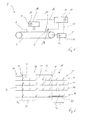
- FIG. 1 schematically simplified, an automated system 2 is shown with a belt conveyor 4, on which a manufacturing product 6 rests.
- the belt conveyor 4 is operated by means of an electric motor 8, and thus changes the position of the finished product 6.
- the automated system 2 has both a gripping and processing head 10 and a light barrier 12, which, like the electric motor 8, are connected via a signal network 14 to a process controller 16.
- signal network 14 an EtherCAT fieldbus system is used.
- the gripping and processing head 10 and the electric motor 8 each represent an actuator and the light barrier 12 is a sensor of the automated system 2.
- These electrical components 8, 10, 12 each include a buffer memory 18, in each of which process data 20 are stored via the signal network 14 are transmitted periodically.
- each electrical component 8, 10, 12 each have a time counter 22, by means of which each of the electrical components 8, 10, 12 is assigned a time window for the transmission of the respective process data.
- a synchronization of the electrical components 8, 10, 12 and the process control 16 is required, which in Fig. 2 is shown.
- the top line shows the time course of the state 24 of the complete automated system 2. This is switched from a standby mode 26, during which the process control 26 is energized, but the electrical components 8, 10, 12 take no action or record data, in an operating state 28 by a change of state 30.
- the electric motor 8 is energized and thus the belt conveyor 4 is set in motion, which causes a change in position of the manufacturing product 6. Also, the manufacturing product 6, as soon as it is located at a suitable position by means of the gripping and machining head 10 is processed.
- the state 24 of the automated system 2 is again transferred to the standby mode 26 by a further state change 30.
- the change of state 24 is initiated by means of a suitable SET command, which is transmitted via the signal network 14.
- the first SET signal which causes the automated system 2 to change from the standby mode 26 to the operating state 28, passes through the signal network 14, this point in time becomes global, relative time information 32 for the synchronization of the electrical components 8, 10, 12 used.
- the time counters 22 of the electrical components 8, 10, 12 are set to zero (0) and the state change 30 is therefore used as a reference 34, starting with the time counters 22 the elapsed time is counted.
- All time counters 22 of the electrical components 8, 10, 12 have a known, same cycle time 36.
- the count of the time counters 22 is substantially the same after any time.
- the count of the time counters here indicates how many cycles have elapsed since the reference value 34, and the local time stamp is the count multiplied by the cycle time 36.
- the cycle time 36 of the electrical components is equal to half of a cycle time 38 of the signal network 14, during which each of the electrical components 8, 10, 12 sends the process data recorded in the respective intermediate memory 18 via the signal network 14 to the process controller 16.
- the order of sending is always the same.
- not all process data that has been recorded by the respective electrical component 8, 10, 12 during a cycle time 38 of the signal network 14 is sent via the signal network 14. Rather, only those Provided data of the process control 16, which are required for proper operation.
- a transfer of the temporally comparatively high-resolution process data, which are stored in the respective buffer memory 18 of the electrical components 8, 10, 12, takes place via the signal network 14, depending on current requirements, for example, if the production product 6 is at a specific Position of the belt conveyor 4 is located, or to check the functionality of the individual electrical component 8, 10, 12.
- the time of transmission here is comparatively arbitrary and can be done both during the operating state 28 and the standby mode 26.
- a communication between the process control 16 and the electrical components 8, 10, 12 via the signal network 14 in a time window 40 is maintained for the already started cycle time 28.
- the electrical components 8, 10, 12 do not receive any further data. Rather, the process data already stored in the respective intermediate memory 18 are sent to the process controller 16 in full temporal resolution, ie process data provided with the cycle time 36 of the time counter 22, in order to determine any signs of wear or otherwise impairing the electrical components 8, 10, 12 ,
Landscapes
- Engineering & Computer Science (AREA)
- Theoretical Computer Science (AREA)
- Computer Networks & Wireless Communication (AREA)
- Signal Processing (AREA)
- Physics & Mathematics (AREA)
- General Engineering & Computer Science (AREA)
- General Physics & Mathematics (AREA)
- Synchronisation In Digital Transmission Systems (AREA)
- General Factory Administration (AREA)
- Electric Clocks (AREA)
Priority Applications (4)
| Application Number | Priority Date | Filing Date | Title |
|---|---|---|---|
| EP12008586.5A EP2746892B1 (fr) | 2012-12-21 | 2012-12-21 | Installation automatisée et procédé de synchronisation d'une installation automatisée |
| JP2013261151A JP2014123947A (ja) | 2012-12-21 | 2013-12-18 | 自動システムおよび自動システムを同期する方法 |
| CN201310712492.2A CN103885396A (zh) | 2012-12-21 | 2013-12-20 | 自动化设备和用于同步化自动化设备的方法 |
| US14/138,100 US9207707B2 (en) | 2012-12-21 | 2013-12-22 | Automated system and method for synchronizing an automated system |
Applications Claiming Priority (1)
| Application Number | Priority Date | Filing Date | Title |
|---|---|---|---|
| EP12008586.5A EP2746892B1 (fr) | 2012-12-21 | 2012-12-21 | Installation automatisée et procédé de synchronisation d'une installation automatisée |
Publications (2)
| Publication Number | Publication Date |
|---|---|
| EP2746892A1 true EP2746892A1 (fr) | 2014-06-25 |
| EP2746892B1 EP2746892B1 (fr) | 2015-12-16 |
Family
ID=47522229
Family Applications (1)
| Application Number | Title | Priority Date | Filing Date |
|---|---|---|---|
| EP12008586.5A Active EP2746892B1 (fr) | 2012-12-21 | 2012-12-21 | Installation automatisée et procédé de synchronisation d'une installation automatisée |
Country Status (4)
| Country | Link |
|---|---|
| US (1) | US9207707B2 (fr) |
| EP (1) | EP2746892B1 (fr) |
| JP (1) | JP2014123947A (fr) |
| CN (1) | CN103885396A (fr) |
Cited By (1)
| Publication number | Priority date | Publication date | Assignee | Title |
|---|---|---|---|---|
| CN111638693A (zh) * | 2020-06-04 | 2020-09-08 | 杭州和利时自动化有限公司 | 一种多个设备控制方法及系统 |
Families Citing this family (2)
| Publication number | Priority date | Publication date | Assignee | Title |
|---|---|---|---|---|
| JP6728842B2 (ja) * | 2016-03-24 | 2020-07-22 | オムロン株式会社 | 光学計測装置 |
| EP4119290A4 (fr) * | 2020-03-09 | 2023-11-22 | Hexagon Metrology Kabushiki Kaisha | Dispositif d'usinage cnc |
Citations (2)
| Publication number | Priority date | Publication date | Assignee | Title |
|---|---|---|---|---|
| EP1657619B1 (fr) | 2004-11-15 | 2008-10-22 | Bosch Rexroth AG | Procédé de synchronisation temporelle dans un système de communication cyclique |
| DE102008049161A1 (de) * | 2008-09-24 | 2010-04-01 | Siemens Aktiengesellschaft | Mikroprozessorsystem mit mehreren signaltechnisch miteinander verbundenen Mikroprozessoren |
Family Cites Families (6)
| Publication number | Priority date | Publication date | Assignee | Title |
|---|---|---|---|---|
| JP3410426B2 (ja) * | 2000-04-07 | 2003-05-26 | 新東工業株式会社 | 設備のメンテナンス支援方法およびそのシステム |
| DE10113260B4 (de) * | 2001-03-16 | 2005-10-20 | Siemens Ag | Synchrones, getaktetes Kommunikationssystem mit Relativuhr und Verfahren zum Aufbau eines solchen Systems |
| DE102004030969A1 (de) * | 2004-06-26 | 2006-01-12 | Robert Bosch Gmbh | Verfahren und Vorrichtung zur Steuerung eines Bussystems sowie entsprechendes Bussystem |
| DE102006021767A1 (de) * | 2006-05-10 | 2007-11-15 | Siemens Ag | Bediengerät zum Informationsaustausch mit einem Feldgerät in einem Automatisierungssystem |
| US8711038B2 (en) * | 2006-10-05 | 2014-04-29 | Her Majesty The Queen In Right Of Canada As Represented By The Minister Of Industry, Through The Communications Research Centre Canada | High-resolution ranging and location finding using multicarrier signals |
| JPWO2010073441A1 (ja) * | 2008-12-26 | 2012-05-31 | シャープ株式会社 | 同期装置、受信装置、同期方法、及び受信方法 |
-
2012
- 2012-12-21 EP EP12008586.5A patent/EP2746892B1/fr active Active
-
2013
- 2013-12-18 JP JP2013261151A patent/JP2014123947A/ja active Pending
- 2013-12-20 CN CN201310712492.2A patent/CN103885396A/zh active Pending
- 2013-12-22 US US14/138,100 patent/US9207707B2/en not_active Expired - Fee Related
Patent Citations (2)
| Publication number | Priority date | Publication date | Assignee | Title |
|---|---|---|---|---|
| EP1657619B1 (fr) | 2004-11-15 | 2008-10-22 | Bosch Rexroth AG | Procédé de synchronisation temporelle dans un système de communication cyclique |
| DE102008049161A1 (de) * | 2008-09-24 | 2010-04-01 | Siemens Aktiengesellschaft | Mikroprozessorsystem mit mehreren signaltechnisch miteinander verbundenen Mikroprozessoren |
Non-Patent Citations (1)
| Title |
|---|
| GIANLUCA CENA ET AL: "Evaluation of EtherCAT Distributed Clock Performance", IEEE TRANSACTIONS ON INDUSTRIAL INFORMATICS, IEEE SERVICE CENTER, NEW YORK, NY, US, vol. 8, no. 1, 1 February 2012 (2012-02-01), pages 20 - 29, XP011398084, ISSN: 1551-3203, DOI: 10.1109/TII.2011.2172434 * |
Cited By (2)
| Publication number | Priority date | Publication date | Assignee | Title |
|---|---|---|---|---|
| CN111638693A (zh) * | 2020-06-04 | 2020-09-08 | 杭州和利时自动化有限公司 | 一种多个设备控制方法及系统 |
| CN111638693B (zh) * | 2020-06-04 | 2021-04-27 | 杭州和利时自动化有限公司 | 一种多个设备控制方法及系统 |
Also Published As
| Publication number | Publication date |
|---|---|
| US9207707B2 (en) | 2015-12-08 |
| CN103885396A (zh) | 2014-06-25 |
| JP2014123947A (ja) | 2014-07-03 |
| US20140177769A1 (en) | 2014-06-26 |
| EP2746892B1 (fr) | 2015-12-16 |
Similar Documents
| Publication | Publication Date | Title |
|---|---|---|
| DE102014106752B4 (de) | Verfahren und Steuereinrichtung zum Betrieb eines berührungslosen Übertragungssystems für einen IO-Link | |
| DE102009017681B4 (de) | Verfahren und Kommunikationssystem zum Ermitteln des Zeitpunktes eines Ereignisses in einem IO-Gerät | |
| WO2002076033A2 (fr) | Systeme de communication synchrone et cadence, comportant des ensembles d'entree/de sortie decentralises, et procede pour integrer des ensembles d'entree/de sortie decentralises dans un tel systeme | |
| EP3220561B1 (fr) | Dispositif et procédé de commande d'une installation automatisée | |
| EP1368728B1 (fr) | Systeme de communication synchrone et cadence, comportant une horloge relative, et procede pour realiser un tel systeme | |
| DE102007005489A1 (de) | Rundgetaktete Maschine, insbesondere Blasformmaschine | |
| EP3673621B1 (fr) | Procédé de transmission de données entre un dispositif de commande central et une pluralité d'appareils décentralisés et dispositifs correspondants | |
| DE102006047026A1 (de) | Verfahren und System zum redundanten Ansteuern einer Slaveeinrichtung | |
| DE102013105097A1 (de) | Steuerungseinrichtung und Verfahren zum Umschalten von Ein-/Ausgabeeinheiten einer Steuerungseinrichtung | |
| EP2746892B1 (fr) | Installation automatisée et procédé de synchronisation d'une installation automatisée | |
| DE2332664C2 (de) | Programmsteuerungssystem | |
| EP3032429B1 (fr) | Procede et dispositif destines a la lecture d'un flux seriel de donnees | |
| EP3632056B1 (fr) | Intitialisation d'un bus local | |
| EP2764592B1 (fr) | Module de sélectivité avec signal d'état en série | |
| EP1307989B1 (fr) | Procede de communication | |
| DE19815647C2 (de) | Verfahren zur Synchronisation einer lokalen auf eine zentrale Zeitbasis, und Vorrichtung zur Durchführung des Verfahrens mit bevorzugten Verwendungen | |
| DE102010002183B4 (de) | Verfahren zur Durchführung in einer Druckmaschine mit mindestens einer Maschineneinheit und mit mehreren Antrieben | |
| DE10229110A1 (de) | Verfahren zur Synchronisation von Knoten eines Kommunikationssystems | |
| DE102007062333B3 (de) | Verfahren zur Übertragung von Multiturn-Modulo-Leitachsdaten | |
| DE102017208825B4 (de) | Übertragen von Daten auf einem Lokalbus | |
| EP0353584B1 (fr) | Système pour machine-outil ou robot avec un dispositif de mesure de position absolue cyclique | |
| EP2138917A1 (fr) | Procédé de synchronisation d'une multitude d'entraînements et entraînement pouvant être exploité selon ce procédé | |
| EP1184755A2 (fr) | Méthode de fonctionnement d'une unité périphérique comprenant un groupe de tête et au moins un groupe d'entrée | |
| DE10048747B4 (de) | Verfahren und Verarbeiten von Prozesssignalen | |
| DE102008001214A1 (de) | Maschineneinheit einer Druckanlage mit mindestens einem von einer Steuereinheit gesteuerten Aktor |
Legal Events
| Date | Code | Title | Description |
|---|---|---|---|
| PUAI | Public reference made under article 153(3) epc to a published international application that has entered the european phase |
Free format text: ORIGINAL CODE: 0009012 |
|
| 17P | Request for examination filed |
Effective date: 20130114 |
|
| AK | Designated contracting states |
Kind code of ref document: A1 Designated state(s): AL AT BE BG CH CY CZ DE DK EE ES FI FR GB GR HR HU IE IS IT LI LT LU LV MC MK MT NL NO PL PT RO RS SE SI SK SM TR |
|
| AX | Request for extension of the european patent |
Extension state: BA ME |
|
| GRAP | Despatch of communication of intention to grant a patent |
Free format text: ORIGINAL CODE: EPIDOSNIGR1 |
|
| INTG | Intention to grant announced |
Effective date: 20150310 |
|
| GRAP | Despatch of communication of intention to grant a patent |
Free format text: ORIGINAL CODE: EPIDOSNIGR1 |
|
| INTG | Intention to grant announced |
Effective date: 20150717 |
|
| GRAS | Grant fee paid |
Free format text: ORIGINAL CODE: EPIDOSNIGR3 |
|
| GRAA | (expected) grant |
Free format text: ORIGINAL CODE: 0009210 |
|
| AK | Designated contracting states |
Kind code of ref document: B1 Designated state(s): AL AT BE BG CH CY CZ DE DK EE ES FI FR GB GR HR HU IE IS IT LI LT LU LV MC MK MT NL NO PL PT RO RS SE SI SK SM TR |
|
| REG | Reference to a national code |
Ref country code: GB Ref legal event code: FG4D Free format text: NOT ENGLISH |
|
| REG | Reference to a national code |
Ref country code: CH Ref legal event code: EP Ref country code: CH Ref legal event code: NV Representative=s name: E. BLUM AND CO. AG PATENT- UND MARKENANWAELTE , CH |
|
| REG | Reference to a national code |
Ref country code: IE Ref legal event code: FG4D Free format text: LANGUAGE OF EP DOCUMENT: GERMAN |
|
| REG | Reference to a national code |
Ref country code: AT Ref legal event code: REF Ref document number: 765847 Country of ref document: AT Kind code of ref document: T Effective date: 20160115 |
|
| REG | Reference to a national code |
Ref country code: DE Ref legal event code: R096 Ref document number: 502012005475 Country of ref document: DE |
|
| REG | Reference to a national code |
Ref country code: NL Ref legal event code: FP |
|
| REG | Reference to a national code |
Ref country code: LT Ref legal event code: MG4D |
|
| PG25 | Lapsed in a contracting state [announced via postgrant information from national office to epo] |
Ref country code: HR Free format text: LAPSE BECAUSE OF FAILURE TO SUBMIT A TRANSLATION OF THE DESCRIPTION OR TO PAY THE FEE WITHIN THE PRESCRIBED TIME-LIMIT Effective date: 20151216 Ref country code: LT Free format text: LAPSE BECAUSE OF FAILURE TO SUBMIT A TRANSLATION OF THE DESCRIPTION OR TO PAY THE FEE WITHIN THE PRESCRIBED TIME-LIMIT Effective date: 20151216 Ref country code: NO Free format text: LAPSE BECAUSE OF FAILURE TO SUBMIT A TRANSLATION OF THE DESCRIPTION OR TO PAY THE FEE WITHIN THE PRESCRIBED TIME-LIMIT Effective date: 20160316 |
|
| PG25 | Lapsed in a contracting state [announced via postgrant information from national office to epo] |
Ref country code: SE Free format text: LAPSE BECAUSE OF FAILURE TO SUBMIT A TRANSLATION OF THE DESCRIPTION OR TO PAY THE FEE WITHIN THE PRESCRIBED TIME-LIMIT Effective date: 20151216 Ref country code: LV Free format text: LAPSE BECAUSE OF FAILURE TO SUBMIT A TRANSLATION OF THE DESCRIPTION OR TO PAY THE FEE WITHIN THE PRESCRIBED TIME-LIMIT Effective date: 20151216 Ref country code: GR Free format text: LAPSE BECAUSE OF FAILURE TO SUBMIT A TRANSLATION OF THE DESCRIPTION OR TO PAY THE FEE WITHIN THE PRESCRIBED TIME-LIMIT Effective date: 20160317 Ref country code: RS Free format text: LAPSE BECAUSE OF FAILURE TO SUBMIT A TRANSLATION OF THE DESCRIPTION OR TO PAY THE FEE WITHIN THE PRESCRIBED TIME-LIMIT Effective date: 20151216 Ref country code: FI Free format text: LAPSE BECAUSE OF FAILURE TO SUBMIT A TRANSLATION OF THE DESCRIPTION OR TO PAY THE FEE WITHIN THE PRESCRIBED TIME-LIMIT Effective date: 20151216 Ref country code: BE Free format text: LAPSE BECAUSE OF NON-PAYMENT OF DUE FEES Effective date: 20151231 |
|
| PG25 | Lapsed in a contracting state [announced via postgrant information from national office to epo] |
Ref country code: ES Free format text: LAPSE BECAUSE OF FAILURE TO SUBMIT A TRANSLATION OF THE DESCRIPTION OR TO PAY THE FEE WITHIN THE PRESCRIBED TIME-LIMIT Effective date: 20151216 Ref country code: IT Free format text: LAPSE BECAUSE OF FAILURE TO SUBMIT A TRANSLATION OF THE DESCRIPTION OR TO PAY THE FEE WITHIN THE PRESCRIBED TIME-LIMIT Effective date: 20151216 Ref country code: CZ Free format text: LAPSE BECAUSE OF FAILURE TO SUBMIT A TRANSLATION OF THE DESCRIPTION OR TO PAY THE FEE WITHIN THE PRESCRIBED TIME-LIMIT Effective date: 20151216 |
|
| PG25 | Lapsed in a contracting state [announced via postgrant information from national office to epo] |
Ref country code: RO Free format text: LAPSE BECAUSE OF FAILURE TO SUBMIT A TRANSLATION OF THE DESCRIPTION OR TO PAY THE FEE WITHIN THE PRESCRIBED TIME-LIMIT Effective date: 20151216 Ref country code: SM Free format text: LAPSE BECAUSE OF FAILURE TO SUBMIT A TRANSLATION OF THE DESCRIPTION OR TO PAY THE FEE WITHIN THE PRESCRIBED TIME-LIMIT Effective date: 20151216 Ref country code: PT Free format text: LAPSE BECAUSE OF FAILURE TO SUBMIT A TRANSLATION OF THE DESCRIPTION OR TO PAY THE FEE WITHIN THE PRESCRIBED TIME-LIMIT Effective date: 20160418 Ref country code: EE Free format text: LAPSE BECAUSE OF FAILURE TO SUBMIT A TRANSLATION OF THE DESCRIPTION OR TO PAY THE FEE WITHIN THE PRESCRIBED TIME-LIMIT Effective date: 20151216 Ref country code: SK Free format text: LAPSE BECAUSE OF FAILURE TO SUBMIT A TRANSLATION OF THE DESCRIPTION OR TO PAY THE FEE WITHIN THE PRESCRIBED TIME-LIMIT Effective date: 20151216 Ref country code: IS Free format text: LAPSE BECAUSE OF FAILURE TO SUBMIT A TRANSLATION OF THE DESCRIPTION OR TO PAY THE FEE WITHIN THE PRESCRIBED TIME-LIMIT Effective date: 20160416 |
|
| REG | Reference to a national code |
Ref country code: DE Ref legal event code: R097 Ref document number: 502012005475 Country of ref document: DE |
|
| REG | Reference to a national code |
Ref country code: IE Ref legal event code: MM4A |
|
| PG25 | Lapsed in a contracting state [announced via postgrant information from national office to epo] |
Ref country code: MC Free format text: LAPSE BECAUSE OF FAILURE TO SUBMIT A TRANSLATION OF THE DESCRIPTION OR TO PAY THE FEE WITHIN THE PRESCRIBED TIME-LIMIT Effective date: 20151216 |
|
| PLBE | No opposition filed within time limit |
Free format text: ORIGINAL CODE: 0009261 |
|
| STAA | Information on the status of an ep patent application or granted ep patent |
Free format text: STATUS: NO OPPOSITION FILED WITHIN TIME LIMIT |
|
| PG25 | Lapsed in a contracting state [announced via postgrant information from national office to epo] |
Ref country code: IE Free format text: LAPSE BECAUSE OF NON-PAYMENT OF DUE FEES Effective date: 20151221 Ref country code: PL Free format text: LAPSE BECAUSE OF FAILURE TO SUBMIT A TRANSLATION OF THE DESCRIPTION OR TO PAY THE FEE WITHIN THE PRESCRIBED TIME-LIMIT Effective date: 20151216 Ref country code: DK Free format text: LAPSE BECAUSE OF FAILURE TO SUBMIT A TRANSLATION OF THE DESCRIPTION OR TO PAY THE FEE WITHIN THE PRESCRIBED TIME-LIMIT Effective date: 20151216 |
|
| 26N | No opposition filed |
Effective date: 20160919 |
|
| REG | Reference to a national code |
Ref country code: FR Ref legal event code: ST Effective date: 20161125 |
|
| PG25 | Lapsed in a contracting state [announced via postgrant information from national office to epo] |
Ref country code: FR Free format text: LAPSE BECAUSE OF NON-PAYMENT OF DUE FEES Effective date: 20160216 |
|
| PG25 | Lapsed in a contracting state [announced via postgrant information from national office to epo] |
Ref country code: SI Free format text: LAPSE BECAUSE OF FAILURE TO SUBMIT A TRANSLATION OF THE DESCRIPTION OR TO PAY THE FEE WITHIN THE PRESCRIBED TIME-LIMIT Effective date: 20151216 |
|
| PG25 | Lapsed in a contracting state [announced via postgrant information from national office to epo] |
Ref country code: HU Free format text: LAPSE BECAUSE OF FAILURE TO SUBMIT A TRANSLATION OF THE DESCRIPTION OR TO PAY THE FEE WITHIN THE PRESCRIBED TIME-LIMIT; INVALID AB INITIO Effective date: 20121221 Ref country code: BG Free format text: LAPSE BECAUSE OF FAILURE TO SUBMIT A TRANSLATION OF THE DESCRIPTION OR TO PAY THE FEE WITHIN THE PRESCRIBED TIME-LIMIT Effective date: 20151216 |
|
| PG25 | Lapsed in a contracting state [announced via postgrant information from national office to epo] |
Ref country code: CY Free format text: LAPSE BECAUSE OF FAILURE TO SUBMIT A TRANSLATION OF THE DESCRIPTION OR TO PAY THE FEE WITHIN THE PRESCRIBED TIME-LIMIT Effective date: 20151216 |
|
| GBPC | Gb: european patent ceased through non-payment of renewal fee |
Effective date: 20161221 |
|
| PG25 | Lapsed in a contracting state [announced via postgrant information from national office to epo] |
Ref country code: MT Free format text: LAPSE BECAUSE OF FAILURE TO SUBMIT A TRANSLATION OF THE DESCRIPTION OR TO PAY THE FEE WITHIN THE PRESCRIBED TIME-LIMIT Effective date: 20151216 |
|
| PG25 | Lapsed in a contracting state [announced via postgrant information from national office to epo] |
Ref country code: GB Free format text: LAPSE BECAUSE OF NON-PAYMENT OF DUE FEES Effective date: 20161221 Ref country code: LU Free format text: LAPSE BECAUSE OF NON-PAYMENT OF DUE FEES Effective date: 20151221 |
|
| PG25 | Lapsed in a contracting state [announced via postgrant information from national office to epo] |
Ref country code: MK Free format text: LAPSE BECAUSE OF FAILURE TO SUBMIT A TRANSLATION OF THE DESCRIPTION OR TO PAY THE FEE WITHIN THE PRESCRIBED TIME-LIMIT Effective date: 20151216 |
|
| PG25 | Lapsed in a contracting state [announced via postgrant information from national office to epo] |
Ref country code: AL Free format text: LAPSE BECAUSE OF FAILURE TO SUBMIT A TRANSLATION OF THE DESCRIPTION OR TO PAY THE FEE WITHIN THE PRESCRIBED TIME-LIMIT Effective date: 20151216 Ref country code: TR Free format text: LAPSE BECAUSE OF FAILURE TO SUBMIT A TRANSLATION OF THE DESCRIPTION OR TO PAY THE FEE WITHIN THE PRESCRIBED TIME-LIMIT Effective date: 20151216 |
|
| PGFP | Annual fee paid to national office [announced via postgrant information from national office to epo] |
Ref country code: NL Payment date: 20211217 Year of fee payment: 10 |
|
| REG | Reference to a national code |
Ref country code: NL Ref legal event code: MM Effective date: 20230101 |
|
| PG25 | Lapsed in a contracting state [announced via postgrant information from national office to epo] |
Ref country code: NL Free format text: LAPSE BECAUSE OF NON-PAYMENT OF DUE FEES Effective date: 20230101 |
|
| REG | Reference to a national code |
Ref country code: CH Ref legal event code: U11 Free format text: ST27 STATUS EVENT CODE: U-0-0-U10-U11 (AS PROVIDED BY THE NATIONAL OFFICE) Effective date: 20260101 |
|
| PGFP | Annual fee paid to national office [announced via postgrant information from national office to epo] |
Ref country code: AT Payment date: 20251215 Year of fee payment: 14 |
|
| PGFP | Annual fee paid to national office [announced via postgrant information from national office to epo] |
Ref country code: DE Payment date: 20251222 Year of fee payment: 14 |
|
| PGFP | Annual fee paid to national office [announced via postgrant information from national office to epo] |
Ref country code: CH Payment date: 20260101 Year of fee payment: 14 |