EP3699384A1 - Joint d'étanchéité doté d'une bande d'étanchéité pouvant être abaissée au moyen d'un mécanisme d'abaissement actionnable à l'aide d'un déclancheur - Google Patents
Joint d'étanchéité doté d'une bande d'étanchéité pouvant être abaissée au moyen d'un mécanisme d'abaissement actionnable à l'aide d'un déclancheur Download PDFInfo
- Publication number
- EP3699384A1 EP3699384A1 EP19166220.4A EP19166220A EP3699384A1 EP 3699384 A1 EP3699384 A1 EP 3699384A1 EP 19166220 A EP19166220 A EP 19166220A EP 3699384 A1 EP3699384 A1 EP 3699384A1
- Authority
- EP
- European Patent Office
- Prior art keywords
- seal
- bearing
- scissor
- trigger
- sealing strip
- Prior art date
- Legal status (The legal status is an assumption and is not a legal conclusion. Google has not performed a legal analysis and makes no representation as to the accuracy of the status listed.)
- Granted
Links
Images






Classifications
-
- E—FIXED CONSTRUCTIONS
- E06—DOORS, WINDOWS, SHUTTERS, OR ROLLER BLINDS IN GENERAL; LADDERS
- E06B—FIXED OR MOVABLE CLOSURES FOR OPENINGS IN BUILDINGS, VEHICLES, FENCES OR LIKE ENCLOSURES IN GENERAL, e.g. DOORS, WINDOWS, BLINDS, GATES
- E06B7/00—Special arrangements or measures in connection with doors or windows
- E06B7/16—Sealing arrangements on wings or parts co-operating with the wings
- E06B7/18—Sealing arrangements on wings or parts co-operating with the wings by means of movable edgings, e.g. draught sealings additionally used for bolting, e.g. by spring force or with operating lever
- E06B7/20—Sealing arrangements on wings or parts co-operating with the wings by means of movable edgings, e.g. draught sealings additionally used for bolting, e.g. by spring force or with operating lever automatically withdrawn when the wing is opened, e.g. by means of magnetic attraction, a pin or an inclined surface, especially for sills
- E06B7/215—Sealing arrangements on wings or parts co-operating with the wings by means of movable edgings, e.g. draught sealings additionally used for bolting, e.g. by spring force or with operating lever automatically withdrawn when the wing is opened, e.g. by means of magnetic attraction, a pin or an inclined surface, especially for sills with sealing strip being moved to a retracted position by elastic means, e.g. springs
Definitions
- Such a seal is from the document EP 3 309 346 A1 known.
- One advantage of this seal is that the length of the trigger is adjustable and the position of the trigger can be adapted to the installation situation in order to set the desired stroke of the seal.
- seals usually have a minimum width of the holding means of approx. 12 mm. There are only a few seals that have a smaller width, for example 8 mm. In many applications, however, seals are required that have a smaller width, for example only a width of 8 mm. There is a need for different models of narrow seals.
- the invention is based on the object of proposing automatic seals, in particular those with scissor elements, which have a small width.
- Every invention contributes to a narrow seal, for example only 8 mm wide.
- a first contribution is made by the invention according to claim 1, according to which the element having the receptacle is forked on one side and has a first and a second fork leg, between which the receptacle is formed.
- triggers have been designed so that they have a receptacle into which a rod or the like is inserted.
- the rod received in the receptacle specifies the size of the receptacle.
- the trigger is designed to be sufficiently resilient in the area of the receptacle so that no damage occurs to the trigger when the forces are transferred from the trigger to the rod.
- the walls of the shutter release that limit the exposure have therefore hitherto had a certain thickness, which means that the shutter release has a certain width.
- the trigger thereby specifies a minimum dimension for the width of the seal.
- the receptacle is formed by the first and the second fork leg.
- the fork legs can be arranged above and below the threaded rod.
- the receptacle then has no side walls. This enables the coupling element to have a narrow design.
- Both the head and the coupling element of the trigger advantageously have guide structures with which it is possible to guide the head and the trigger on the holding means of the seal in the actuation direction of the trigger. This prevents the head or the coupling element from giving way to the side when actuated or the trigger from buckling at the connection point between the head and the trigger. Forces and moments that do not act in the actuating direction can thereby be diverted into the holding means. About the connection between the Head and the coupling element only needs to be transferred in the direction of actuation.
- a narrow seal can also be created if, according to the second invention, in a seal with scissors elements mentioned at the outset, the first scissors element has an end, viewed from the first bearing, beyond the third bearing and displaceable to the sealing strip, which is at a distance from the third bearing, which is at least 50% of the distance between the second bearing and the third bearing. This results in a section of the first scissors element between the third bearing and the displaceable end, which section can be used to guide the first scissors element through the sealing strip and / or a displacement part of the lowering mechanism.
- the sealing strip can have a guide channel for guiding the displaceable end of the first scissors element through the sealing strip.
- the section of the first scissor element lying between the third bearing and the sliding end can have a slot on a side facing the holding means.
- the sliding part can be inserted into the slot engage and guide the first scissors element in particular both at the beginning of a lowering movement of the sealing strip, but also at the end of an upward movement of the sealing strip.
- the third bearing is formed by a single pin of one of the two scissor elements and a recess in the other of the two scissor elements into which the pin is inserted.
- a narrow seal can in particular also be created in that the third bearing is formed by a single pin of one of the two scissor elements and a recess in the other of the two scissor elements into which the pin is inserted.
- the rivets used to connect the scissor elements see CH 465 830
- locking connections see EP 3 284 896 A1
- the scissor elements are not only mounted in the first and second bearings, but are also guided at the displaceable ends in the longitudinal direction of the seal, advantageously in such a way that that the scissor elements can perform little or no movement transversely to the longitudinal direction of the seal.
- the plug connection established by the recess in one scissor element and the pin in the other scissor element can suffice to form a bearing that is suitable for the transmission of forces between the scissors elements.
- a narrow seal can also be created if the second bearing is formed by a single pin on the second scissor element and a channel in the sealing strip in which the pin is pivotably and displaceably arranged.
- the channel in the sealing strip can have a base, two spaced-apart side walls and a web protruding from a first of the two side walls in the direction of the second of the two side walls.
- a slot can then remain between a free end of the web and the second side wall, through which the second scissors element reaches.
- the pin of the second bearing can engage behind this web.
- the second scissor element can have an end that is located on the other side of the third bearing and can be displaced parallel to the sealing strip when viewed from the second bearing.
- the aforementioned sliding part which is displaced parallel to the longitudinal direction of the seal when the seal is actuated, can be coupled to the displaceable end of the second scissor element in order to move the sliding part towards the scissor elements and ultimately towards the sealing strip when the seal is actuated transfer.
- a good fixation of the first scissors element of a seal according to the invention in a direction transverse to the longitudinal direction of the seal can be achieved in that the first scissors element is forked between the first and the third bearing or has a window.
- outwardly protruding pins can be provided which engage in recesses in the holding part or in recesses in a part connected to the holding part.
- a good fixation of the second scissors element of a seal according to the invention in a direction transverse to the longitudinal direction of the seal can be achieved in that the second scissors element is forked between the displaceable end and the third bearing or has a window.
- the sliding part can reach through between fork legs of the forked section of the first and / or second scissor element and / or through the window of the first and / or second scissor element. This makes it possible to fix it in the transverse direction to the longitudinal direction of the seal.
- the sliding part is preferably guided by means of one or more guide parts which are fastened in the holding element.
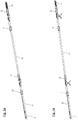
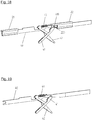
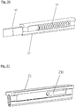
- the automatically lowerable door seal according to the invention shown in the figures has a holding means 2 which has a housing 20.
- This can be fastened in a groove of a door using fastening brackets 1, for example. With other fastening means, fastening to an outside of a door is also possible.
- the housing 20 has a uniform profile extending in a longitudinal direction.
- the housing is preferably an extruded aluminum profile.
- a lowering mechanism 4 is fastened to the housing 20 in the housing 20 via guide parts 21, 22, 23. With this lowering mechanism 4, a sealing strip 5 can be moved from a raised position into a lowered position.
- the sealing strip 5 is in two parts and comprises an inner rail 50 and a sealing profile 51, which are tight against a surface, for example the floor.
- the lowering mechanism 4 is coupled to a trigger 3, by means of which a force necessary for actuating the seal can be introduced into the lowering mechanism 4.
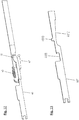
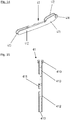
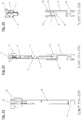
- the trigger 3 of the seal according to the invention is constructed in two parts. It has a head 31 and a coupling element 32. The relative position of head 31 and coupling element 32 to one another can be changed. This makes it possible to adjust the length of the trigger in the longitudinal direction. A length adjustment of a trigger can be used to adjust the stroke of a seal.
- the head 31 of the trigger 3 has a stop surface 310 via which an external force can be introduced into the trigger 3 or the lowering mechanism 4.
- the head 31 has a support body 311 on which the stop surface 310 is provided is.
- a guide structure 312 is provided on an upper side of the support body 311. This is formed by two laterally protruding webs which are arranged displaceably in complementary guide structures of the outer profile.
- the head also has a threaded rod 313 which connects to the support body 311 on a side facing away from the stop surface 310. The threaded rod 313 is used to connect the head 31 to the coupling element 32 of the trigger 3.
- the coupling element 32 of the trigger 3 also has a support body, namely the support body 320.
- This support body 320 initially carries guide structures 321, which are designed exactly like the guide structures 312 of the head 31.
- the coupling element 32 is forked on a side facing the head 31.
- the inner sides of the fork legs 322, 323 facing one another are curved in a concave manner. Thread sections into which the threaded rod 313 is screwed are provided on the inner sides. The thread sections form an incomplete thread which is open on the sides.
- the threaded rod 313 is held in this incomplete thread by the thread sections on the inner sides of the fork legs 322, 323 in the longitudinal direction of the seal. In the transverse direction, the threaded rod 313 is held by the concave curvature of the thread sections. Unlike a complete thread, which can absorb transverse forces very well, the incomplete thread can only absorb small transverse forces. However, because the guide structures 312 and 321 are provided on both the head 31 and the coupling element 32, and because the head 31 and the coupling element 32 are fixed in the transverse direction of the seal, there are hardly any transverse forces that lead to this could cause the threaded rod 313 to slip out of the incomplete thread formed by the fork legs 322, 323.
- the rod 313 could be toothed.
- the insides of the fork legs 322, 323 could be toothed, so that the rod 313 can be locked between the fork legs.
- connection structure 325 is provided, which is used to connect the trigger to the lowering mechanism 4.
- the guide parts 21, 22, 23 are molded parts that have an outer contour adapted to the housing 20, so that the guide parts 21, 22, 23 can be pushed into the housing 20 and fastened there.
- the housing 20 has inwardly protruding webs 200, which are engaged from behind by complementary connecting structures of the guide parts 21, 22, 23 as well as by the guide structures 312, 321 of the head 3.
- First guide parts 21 and second guide parts 22 of the guide parts 21, 22, 23 have a channel through which a rod 40 is passed.
- This rod is multi-part and has several successive sections that are connected to one another.
- One of these sections is a sliding part 401 which has a special function for the lowering mechanism 4 and will be described in more detail below.
- Another portion of the rod 40 is connected to the trigger.
- This section has a connection structure 49 which is coupled to the connection structure 325 of the trigger 3.
- a third guide part 23 of the guide parts 21, 22, 23 is provided at the end of the rod 40.
- This third guide part 23 has a receptacle into which the end of the rod 40 is inserted.
- a return spring 44 of the lowering mechanism is arranged on a mandrel 230. This return spring 44 brings about a transition of the seal from the actuated to the non-actuated state after the release of the trigger 3. To this end, the return spring presses on the end of the rod 40 which is arranged in the receptacle of the third guide part 22.
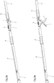
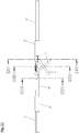
- the rod 40 is coupled to two identical scissor mechanisms, which include a first scissor element 41 and a second scissor element 42.
- the first scissors element is pivotably mounted on the second guide part 22 via a first bearing L1.
- the second scissor element 42 is pivotably connected to an inner profile 50 of the sealing strip 5 in a second bearing L2.
- the first bearing L1 and the second bearing L2 have pivot axes which lie in a plane perpendicular to the longitudinal direction of the seal.
- the first scissor element 41 and the second scissor element 42 are mounted on one another such that they can pivot with respect to one another.
- the first, second and third bearings L1, L2, L3 are pivot bearings.
- the first scissors element 41 is forked at the end supported in the first bearing L1.
- the fork legs 413 created by the fork have outwardly projecting bearing journals 410 which are mounted in recesses 220 in the second bearing part 22.
- the journals 410 and the recesses 220 form the first bearing L1.
- the two fork legs 413 are spaced apart so that the rod 40 can be passed between the two fork legs.
- the first scissor element 41 has a further bearing pin 411 which, together with a recess 421 which is provided in the second scissor element 42 and into which the bearing pin 411 is inserted, forms the third bearing L3.
- the first scissor element has an end 413, viewed from the second bearing L2, lying beyond the third bearing L3.
- a section 412 of the first scissor element extends between this end 413 and the third bearing L3.
- the end 413 is guided in a channel of the inner rail 50, which is delimited by side walls 501, 502 and a web 503 projecting from the side wall 502 in the direction of the first side wall 501.
- the channel forms a linear bearing in which the end 413 is guided.
- the section 412 On its side facing the rod 40, the section 412 has a slot which is approximately as wide as the rod 40. In the non-actuated state of the seal, the rod 40 engages in the slot.
- the position of the first scissors element is held in the transverse direction by the engagement of the rod 50 in the slot and in particular by the guide in the channel.
- the second bearing L2 in which the second scissor element 42 and the inner rail 50 are mounted on one another, is formed by a bearing pin 420 and a channel through the bottom 500, the side walls 501, 502 and the side wall 502 in the direction of the first side wall 501 protruding web 503 is formed.
- the web 503 is engaged from behind by the bearing pin 420.
- the second scissor element has an end 423, viewed from the second bearing L2, lying beyond the third bearing. This end 423 is connected to the rod 40 via a fourth bearing L4.
- the fourth bearing L2 is a bearing with two straight lines of freedom, which allow rotation and displacement of the end of the second scissor element 42 relative to the rod 40.
- the second scissors element In the transverse direction, the second scissors element is not displaceable in the second bearing or in the fourth bearing. As a result, the second scissors element cannot be displaced in the transverse direction, or at most only slightly.
- the end of the second scissor element 42 is prevented from being displaced with respect to the rod 40 by a spring 43 which pulls the end 423 of the second scissor element 42 to an edge of a recess 4011 of the sliding part 401.
- the spring 43 is suspended from the end 423 of the second scissors element 42 and from a hook 4010 of the rod 40. Only in special cases do the end 423 of the second scissor element and the edge of the recess 4011 detach from one another against the tension of the spring 43.
- the end 423 of the second scissors element is displaced with respect to the first bearing L1 which is fixedly connected to the housing 20 via the second guide part 22.
- the second bearing L2 which connects the second scissor element 42 to the inner profile 50, is lowered linearly downwards due to the connection of the first and second scissor elements 41, 42 in the third bearing.
- the sealing strip 5 is thereby lowered transversely to the longitudinal direction of the seal and pressed against the floor, so that the Sealing profile 51 rests against the floor. Because two identical scissor mechanisms are provided and these are actuated synchronously by the rod 40, the sealing strip 5 is lowered parallel to the housing 2.
- the sealing strip 5 is now on the floor, it cannot be moved further downwards.
- the second bearing L2 can then not be moved any further downwards, as a result of which the end 423 of the second scissor element is prevented from further movement with the rod 40. If, however, pressure is then further exerted on the rod 40 via the trigger and this pressure exceeds the force of the spring 43, the end 423 of the second scissor element 42 detaches from the edge of the recess 4011 and the end 423 moves in the recess 4011, since the rod 40 is displaced relative to the end 423. This interaction of the recess 4011, the end 423 of the second scissor element 42 and the spring 43 prevents the lowering mechanism 4 from being overloaded, which could lead to damage to the seal.
- the end 423 of the second scissors element and a section 422 between the end 423 and the third bearing L3 have a window through which the rod 40 is guided.
- circular segment-like structures are provided. These lie against the inside of a web 201 of the housing 20 or are arranged at only a small distance from the inside of this web 201 and move along the inside of the housing 20 when the seal is actuated, possibly at a distance.
- the trigger 3 is also designed in two parts. It has a head 31 and a coupling element 32. The relative position of head 31 and coupling element 32 to one another can be changed. This makes it possible to adjust the length of the trigger in the longitudinal direction. A length adjustment of a trigger can be used to adjust the stroke of a seal.
- the head 31 of the trigger 3 of the variant also has a stop surface 310 via which an external force can be introduced into the trigger 3 or the lowering mechanism 4.
- the head 31 also has a support body 311 on which the stop surface 310 is provided.
- a guide structure 312 is also provided on an upper side of the support body 311. This is in turn formed by two laterally protruding webs which are arranged displaceably in complementary guide structures of the outer profile.
- the head also has a receptacle 314 that is internally threaded.
- the coupling element 32 of the release 3 of the variant also has a support body, namely the support body 320.
- This support body 320 also carries guide structures 321, which are designed exactly like the guide structures 312 of the head 31.
- the coupling element 32 has a threaded rod 326 on a side facing the head 31. This threaded rod is on the side flattened and smooth. Only an upper side and a lower side of the rod are rounded and have sections of the thread turn of a conventional thread.
- the threaded rod 326 has an incomplete thread that is screwed into the receptacle 314.
- connection structure 325 is provided, which is used to connect the trigger to the lowering mechanism 4.
Landscapes
- Engineering & Computer Science (AREA)
- Civil Engineering (AREA)
- Structural Engineering (AREA)
- Specific Sealing Or Ventilating Devices For Doors And Windows (AREA)
- Bearings For Parts Moving Linearly (AREA)
- Slide Fasteners (AREA)
Priority Applications (3)
| Application Number | Priority Date | Filing Date | Title |
|---|---|---|---|
| EP22181870.1A EP4105432B1 (fr) | 2019-02-20 | 2019-03-29 | Joint d'étanchéité doté d'une bande d'étanchéité pouvant être abaissée au moyen d'un mécanisme d'abaissement actionnable à l'aide d'un déclancheur |
| EP19216649.4A EP3699385B1 (fr) | 2019-02-20 | 2019-12-16 | Joint automatique d'étanchéité de porte doté d'au moins un moyen de maintien, d'au moins un mécanisme de ciseaux pourvu de deux éléments de ciseaux et d'une bande d'étanchéité |
| EP20158446.3A EP3699386B1 (fr) | 2019-02-20 | 2020-02-20 | Joint automatique d'étanchéité de porte doté un moyen pour guider une tige de pousser et methode pour positioner ladite tige de pousser dans un bôtier pour ledit joint d'étanchéité |
Applications Claiming Priority (1)
| Application Number | Priority Date | Filing Date | Title |
|---|---|---|---|
| EP19158350 | 2019-02-20 |
Related Child Applications (2)
| Application Number | Title | Priority Date | Filing Date |
|---|---|---|---|
| EP22181870.1A Division EP4105432B1 (fr) | 2019-02-20 | 2019-03-29 | Joint d'étanchéité doté d'une bande d'étanchéité pouvant être abaissée au moyen d'un mécanisme d'abaissement actionnable à l'aide d'un déclancheur |
| EP22181870.1A Division-Into EP4105432B1 (fr) | 2019-02-20 | 2019-03-29 | Joint d'étanchéité doté d'une bande d'étanchéité pouvant être abaissée au moyen d'un mécanisme d'abaissement actionnable à l'aide d'un déclancheur |
Publications (2)
| Publication Number | Publication Date |
|---|---|
| EP3699384A1 true EP3699384A1 (fr) | 2020-08-26 |
| EP3699384B1 EP3699384B1 (fr) | 2022-08-17 |
Family
ID=65529424
Family Applications (5)
| Application Number | Title | Priority Date | Filing Date |
|---|---|---|---|
| EP22181870.1A Active EP4105432B1 (fr) | 2019-02-20 | 2019-03-29 | Joint d'étanchéité doté d'une bande d'étanchéité pouvant être abaissée au moyen d'un mécanisme d'abaissement actionnable à l'aide d'un déclancheur |
| EP19166220.4A Active EP3699384B1 (fr) | 2019-02-20 | 2019-03-29 | Joint d'étanchéité doté d'une bande d'étanchéité pouvant être abaissée au moyen d'un mécanisme d'abaissement actionnable à l'aide d'un déclancheur |
| EP19216649.4A Active EP3699385B1 (fr) | 2019-02-20 | 2019-12-16 | Joint automatique d'étanchéité de porte doté d'au moins un moyen de maintien, d'au moins un mécanisme de ciseaux pourvu de deux éléments de ciseaux et d'une bande d'étanchéité |
| EP20158446.3A Active EP3699386B1 (fr) | 2019-02-20 | 2020-02-20 | Joint automatique d'étanchéité de porte doté un moyen pour guider une tige de pousser et methode pour positioner ladite tige de pousser dans un bôtier pour ledit joint d'étanchéité |
| EP20168063.4A Active EP3868994B1 (fr) | 2019-02-20 | 2020-04-03 | Joint d'étanchéité pourvu de modules comportant un mécanisme d'abaissement |
Family Applications Before (1)
| Application Number | Title | Priority Date | Filing Date |
|---|---|---|---|
| EP22181870.1A Active EP4105432B1 (fr) | 2019-02-20 | 2019-03-29 | Joint d'étanchéité doté d'une bande d'étanchéité pouvant être abaissée au moyen d'un mécanisme d'abaissement actionnable à l'aide d'un déclancheur |
Family Applications After (3)
| Application Number | Title | Priority Date | Filing Date |
|---|---|---|---|
| EP19216649.4A Active EP3699385B1 (fr) | 2019-02-20 | 2019-12-16 | Joint automatique d'étanchéité de porte doté d'au moins un moyen de maintien, d'au moins un mécanisme de ciseaux pourvu de deux éléments de ciseaux et d'une bande d'étanchéité |
| EP20158446.3A Active EP3699386B1 (fr) | 2019-02-20 | 2020-02-20 | Joint automatique d'étanchéité de porte doté un moyen pour guider une tige de pousser et methode pour positioner ladite tige de pousser dans un bôtier pour ledit joint d'étanchéité |
| EP20168063.4A Active EP3868994B1 (fr) | 2019-02-20 | 2020-04-03 | Joint d'étanchéité pourvu de modules comportant un mécanisme d'abaissement |
Country Status (2)
| Country | Link |
|---|---|
| EP (5) | EP4105432B1 (fr) |
| DK (1) | DK3699384T3 (fr) |
Cited By (1)
| Publication number | Priority date | Publication date | Assignee | Title |
|---|---|---|---|---|
| EP4001577A1 (fr) * | 2020-11-24 | 2022-05-25 | Athmer OHG | Joint d'étanchéité automatique doté d'un ressort de surcharge en élastomère |
Families Citing this family (1)
| Publication number | Priority date | Publication date | Assignee | Title |
|---|---|---|---|---|
| CZ2020558A3 (cs) | 2020-10-13 | 2022-04-27 | RenĂ© Göndör | Sestava pohyblivé těsnicí lišty dveřního křídla a dveřní křídlo s touto sestavou |
Citations (6)
| Publication number | Priority date | Publication date | Assignee | Title |
|---|---|---|---|---|
| CH465830A (de) | 1967-10-03 | 1968-11-30 | Arquint Joseph | Türabdichtung gegenüber einem schwellenlosen Boden |
| GB2304776A (en) * | 1995-09-06 | 1997-03-26 | Raven Products Pty Ltd | Retractable door seal |
| DE20306091U1 (de) * | 2003-04-15 | 2003-07-03 | Fa. F. Athmer, 59757 Arnsberg | Türdichtungsvorrichtung |
| DE602004009845T2 (de) | 2003-02-21 | 2008-08-28 | Industrie- En Handelsonderneming Elton B.V. | Dichtungsanordnung für eine Tür |
| EP3284896A1 (fr) | 2016-08-18 | 2018-02-21 | Athmer oHG | Mécanisme en ciseaux pour un joint d'étanchéité et joint d'étanchéité comprenant un tel mécanisme en ciseaux |
| EP3309346A1 (fr) | 2016-10-11 | 2018-04-18 | Athmer oHG | Joint doté d'un déclencheur guidé réglable |
Family Cites Families (2)
| Publication number | Priority date | Publication date | Assignee | Title |
|---|---|---|---|---|
| KR200183456Y1 (ko) * | 1999-12-22 | 2000-05-15 | 이강호 | 문턱제거형 도어의 기밀장치 |
| IT1314655B1 (it) * | 2000-03-10 | 2002-12-31 | Aldo Comaglio | Dispositivo parafreddo perfezionato per porte |
-
2019
- 2019-03-29 DK DK19166220.4T patent/DK3699384T3/da active
- 2019-03-29 EP EP22181870.1A patent/EP4105432B1/fr active Active
- 2019-03-29 EP EP19166220.4A patent/EP3699384B1/fr active Active
- 2019-12-16 EP EP19216649.4A patent/EP3699385B1/fr active Active
-
2020
- 2020-02-20 EP EP20158446.3A patent/EP3699386B1/fr active Active
- 2020-04-03 EP EP20168063.4A patent/EP3868994B1/fr active Active
Patent Citations (6)
| Publication number | Priority date | Publication date | Assignee | Title |
|---|---|---|---|---|
| CH465830A (de) | 1967-10-03 | 1968-11-30 | Arquint Joseph | Türabdichtung gegenüber einem schwellenlosen Boden |
| GB2304776A (en) * | 1995-09-06 | 1997-03-26 | Raven Products Pty Ltd | Retractable door seal |
| DE602004009845T2 (de) | 2003-02-21 | 2008-08-28 | Industrie- En Handelsonderneming Elton B.V. | Dichtungsanordnung für eine Tür |
| DE20306091U1 (de) * | 2003-04-15 | 2003-07-03 | Fa. F. Athmer, 59757 Arnsberg | Türdichtungsvorrichtung |
| EP3284896A1 (fr) | 2016-08-18 | 2018-02-21 | Athmer oHG | Mécanisme en ciseaux pour un joint d'étanchéité et joint d'étanchéité comprenant un tel mécanisme en ciseaux |
| EP3309346A1 (fr) | 2016-10-11 | 2018-04-18 | Athmer oHG | Joint doté d'un déclencheur guidé réglable |
Cited By (1)
| Publication number | Priority date | Publication date | Assignee | Title |
|---|---|---|---|---|
| EP4001577A1 (fr) * | 2020-11-24 | 2022-05-25 | Athmer OHG | Joint d'étanchéité automatique doté d'un ressort de surcharge en élastomère |
Also Published As
| Publication number | Publication date |
|---|---|
| DK3699384T3 (da) | 2022-10-24 |
| EP3699386A1 (fr) | 2020-08-26 |
| EP3868994B1 (fr) | 2023-09-27 |
| EP4105432A1 (fr) | 2022-12-21 |
| EP4105432B1 (fr) | 2025-05-07 |
| EP3868994A1 (fr) | 2021-08-25 |
| EP3699386B1 (fr) | 2022-01-05 |
| EP3699385B1 (fr) | 2022-02-09 |
| EP3699385A1 (fr) | 2020-08-26 |
| EP3699384B1 (fr) | 2022-08-17 |
Similar Documents
| Publication | Publication Date | Title |
|---|---|---|
| EP2474698B1 (fr) | Dispositif d'étanchéité doté d'un profil d'étanchéité et d'un mécanisme destiné au déplacement du profil d'étanchéité lors de l'actionnement du mécanisme | |
| WO2015018526A1 (fr) | Ferrure servant à fixer un objet à un rail | |
| EP3284898A1 (fr) | Joint d'étanchéité comprenant un couteau d'étanchéité pouvant s'abaisser à l'aide d'un mécanisme à ciseaux, un mécanisme de surcharge et un boîtier module | |
| EP2634350B1 (fr) | Joint amovible, notamment joint de porte coulissante | |
| EP4105432B1 (fr) | Joint d'étanchéité doté d'une bande d'étanchéité pouvant être abaissée au moyen d'un mécanisme d'abaissement actionnable à l'aide d'un déclancheur | |
| EP3260646B1 (fr) | Escabeau comprenant un dispositif de sécurisation dans sa position déployée | |
| DE2914448C2 (de) | Vorrichtung zum Verschieben der Filterplatten einer Filterpresse | |
| DE102011013138B3 (de) | Vorrichtung zum Einsetzen eines Kämpfers in einen Tür- oder Fensterrahmen | |
| EP3112577A1 (fr) | Joint abaissable | |
| DE202005008613U1 (de) | Teleskoprohr | |
| EP2233039B1 (fr) | Guidage pour tiroirs | |
| EP2439362B1 (fr) | Barre anti-panique à compression | |
| EP3599335B1 (fr) | Joint d'étanchéité abaissable, en particulier pour portes coulissantes | |
| EP4276267B1 (fr) | Joint d'étanchéité, notamment pour portes coulissantes ou portes coulissantes | |
| DE8535142U1 (de) | Ausziehtisch | |
| EP3859119A1 (fr) | Joint d'étanchéité automatique doté d'un mécanisme de surcharge et/ou d'un mécanisme de mise à zéro doté d'un ressort doté d'un profilé d'arbre, triangulaire, de dent de scie ou d'un profilé analogue | |
| DE1630894C3 (de) | Gelenkbeschlag zum stufenlosen Ver stellen der Ruckenlehnenneigung eines Kraftfahrzeugsitzes | |
| DE29701673U1 (de) | Türfeststeller | |
| EP4407136B1 (fr) | Raccord d'angle avec élément d'expansion | |
| EP3940183B1 (fr) | Moyen de guidage pour une barre de transmission dans un joint automatique et joint automatique doté d'une telle barre de transmission | |
| EP3783176B1 (fr) | Ferrure de tige d'entraînement, fermeture de porte ou de fenêtre et agencement de porte ou de fenêtre | |
| WO2010108742A1 (fr) | Dispositif de réglage | |
| DE3744295A1 (de) | Klemmvorrichtung zum festklemmen einer linear beweglichen stange | |
| EP3768930B1 (fr) | Dispositif de joint d'étanchéité | |
| DE20202200U1 (de) | Hydraulisches Pressgerät mit Rückstellbegrenzung |
Legal Events
| Date | Code | Title | Description |
|---|---|---|---|
| PUAI | Public reference made under article 153(3) epc to a published international application that has entered the european phase |
Free format text: ORIGINAL CODE: 0009012 |
|
| STAA | Information on the status of an ep patent application or granted ep patent |
Free format text: STATUS: THE APPLICATION HAS BEEN PUBLISHED |
|
| AK | Designated contracting states |
Kind code of ref document: A1 Designated state(s): AL AT BE BG CH CY CZ DE DK EE ES FI FR GB GR HR HU IE IS IT LI LT LU LV MC MK MT NL NO PL PT RO RS SE SI SK SM TR |
|
| AX | Request for extension of the european patent |
Extension state: BA ME |
|
| STAA | Information on the status of an ep patent application or granted ep patent |
Free format text: STATUS: REQUEST FOR EXAMINATION WAS MADE |
|
| 17P | Request for examination filed |
Effective date: 20210226 |
|
| RBV | Designated contracting states (corrected) |
Designated state(s): AL AT BE BG CH CY CZ DE DK EE ES FI FR GB GR HR HU IE IS IT LI LT LU LV MC MK MT NL NO PL PT RO RS SE SI SK SM TR |
|
| GRAP | Despatch of communication of intention to grant a patent |
Free format text: ORIGINAL CODE: EPIDOSNIGR1 |
|
| STAA | Information on the status of an ep patent application or granted ep patent |
Free format text: STATUS: GRANT OF PATENT IS INTENDED |
|
| INTG | Intention to grant announced |
Effective date: 20220301 |
|
| GRAS | Grant fee paid |
Free format text: ORIGINAL CODE: EPIDOSNIGR3 |
|
| GRAA | (expected) grant |
Free format text: ORIGINAL CODE: 0009210 |
|
| STAA | Information on the status of an ep patent application or granted ep patent |
Free format text: STATUS: THE PATENT HAS BEEN GRANTED |
|
| AK | Designated contracting states |
Kind code of ref document: B1 Designated state(s): AL AT BE BG CH CY CZ DE DK EE ES FI FR GB GR HR HU IE IS IT LI LT LU LV MC MK MT NL NO PL PT RO RS SE SI SK SM TR |
|
| REG | Reference to a national code |
Ref country code: CH Ref legal event code: EP |
|
| REG | Reference to a national code |
Ref country code: DE Ref legal event code: R096 Ref document number: 502019005302 Country of ref document: DE |
|
| REG | Reference to a national code |
Ref country code: IE Ref legal event code: FG4D Free format text: LANGUAGE OF EP DOCUMENT: GERMAN |
|
| REG | Reference to a national code |
Ref country code: AT Ref legal event code: REF Ref document number: 1512298 Country of ref document: AT Kind code of ref document: T Effective date: 20220915 |
|
| REG | Reference to a national code |
Ref country code: DK Ref legal event code: T3 Effective date: 20221017 |
|
| REG | Reference to a national code |
Ref country code: SE Ref legal event code: TRGR |
|
| REG | Reference to a national code |
Ref country code: NO Ref legal event code: T2 Effective date: 20220817 |
|
| REG | Reference to a national code |
Ref country code: NL Ref legal event code: FP |
|
| REG | Reference to a national code |
Ref country code: LT Ref legal event code: MG9D |
|
| PG25 | Lapsed in a contracting state [announced via postgrant information from national office to epo] |
Ref country code: RS Free format text: LAPSE BECAUSE OF FAILURE TO SUBMIT A TRANSLATION OF THE DESCRIPTION OR TO PAY THE FEE WITHIN THE PRESCRIBED TIME-LIMIT Effective date: 20220817 Ref country code: PT Free format text: LAPSE BECAUSE OF FAILURE TO SUBMIT A TRANSLATION OF THE DESCRIPTION OR TO PAY THE FEE WITHIN THE PRESCRIBED TIME-LIMIT Effective date: 20221219 Ref country code: LV Free format text: LAPSE BECAUSE OF FAILURE TO SUBMIT A TRANSLATION OF THE DESCRIPTION OR TO PAY THE FEE WITHIN THE PRESCRIBED TIME-LIMIT Effective date: 20220817 Ref country code: LT Free format text: LAPSE BECAUSE OF FAILURE TO SUBMIT A TRANSLATION OF THE DESCRIPTION OR TO PAY THE FEE WITHIN THE PRESCRIBED TIME-LIMIT Effective date: 20220817 Ref country code: FI Free format text: LAPSE BECAUSE OF FAILURE TO SUBMIT A TRANSLATION OF THE DESCRIPTION OR TO PAY THE FEE WITHIN THE PRESCRIBED TIME-LIMIT Effective date: 20220817 |
|
| PG25 | Lapsed in a contracting state [announced via postgrant information from national office to epo] |
Ref country code: PL Free format text: LAPSE BECAUSE OF FAILURE TO SUBMIT A TRANSLATION OF THE DESCRIPTION OR TO PAY THE FEE WITHIN THE PRESCRIBED TIME-LIMIT Effective date: 20220817 Ref country code: IS Free format text: LAPSE BECAUSE OF FAILURE TO SUBMIT A TRANSLATION OF THE DESCRIPTION OR TO PAY THE FEE WITHIN THE PRESCRIBED TIME-LIMIT Effective date: 20221217 Ref country code: HR Free format text: LAPSE BECAUSE OF FAILURE TO SUBMIT A TRANSLATION OF THE DESCRIPTION OR TO PAY THE FEE WITHIN THE PRESCRIBED TIME-LIMIT Effective date: 20220817 Ref country code: GR Free format text: LAPSE BECAUSE OF FAILURE TO SUBMIT A TRANSLATION OF THE DESCRIPTION OR TO PAY THE FEE WITHIN THE PRESCRIBED TIME-LIMIT Effective date: 20221118 |
|
| PG25 | Lapsed in a contracting state [announced via postgrant information from national office to epo] |
Ref country code: SM Free format text: LAPSE BECAUSE OF FAILURE TO SUBMIT A TRANSLATION OF THE DESCRIPTION OR TO PAY THE FEE WITHIN THE PRESCRIBED TIME-LIMIT Effective date: 20220817 Ref country code: RO Free format text: LAPSE BECAUSE OF FAILURE TO SUBMIT A TRANSLATION OF THE DESCRIPTION OR TO PAY THE FEE WITHIN THE PRESCRIBED TIME-LIMIT Effective date: 20220817 Ref country code: ES Free format text: LAPSE BECAUSE OF FAILURE TO SUBMIT A TRANSLATION OF THE DESCRIPTION OR TO PAY THE FEE WITHIN THE PRESCRIBED TIME-LIMIT Effective date: 20220817 Ref country code: CZ Free format text: LAPSE BECAUSE OF FAILURE TO SUBMIT A TRANSLATION OF THE DESCRIPTION OR TO PAY THE FEE WITHIN THE PRESCRIBED TIME-LIMIT Effective date: 20220817 |
|
| REG | Reference to a national code |
Ref country code: DE Ref legal event code: R097 Ref document number: 502019005302 Country of ref document: DE |
|
| PG25 | Lapsed in a contracting state [announced via postgrant information from national office to epo] |
Ref country code: SK Free format text: LAPSE BECAUSE OF FAILURE TO SUBMIT A TRANSLATION OF THE DESCRIPTION OR TO PAY THE FEE WITHIN THE PRESCRIBED TIME-LIMIT Effective date: 20220817 Ref country code: EE Free format text: LAPSE BECAUSE OF FAILURE TO SUBMIT A TRANSLATION OF THE DESCRIPTION OR TO PAY THE FEE WITHIN THE PRESCRIBED TIME-LIMIT Effective date: 20220817 |
|
| PLBE | No opposition filed within time limit |
Free format text: ORIGINAL CODE: 0009261 |
|
| STAA | Information on the status of an ep patent application or granted ep patent |
Free format text: STATUS: NO OPPOSITION FILED WITHIN TIME LIMIT |
|
| PG25 | Lapsed in a contracting state [announced via postgrant information from national office to epo] |
Ref country code: AL Free format text: LAPSE BECAUSE OF FAILURE TO SUBMIT A TRANSLATION OF THE DESCRIPTION OR TO PAY THE FEE WITHIN THE PRESCRIBED TIME-LIMIT Effective date: 20220817 |
|
| 26N | No opposition filed |
Effective date: 20230519 |
|
| P01 | Opt-out of the competence of the unified patent court (upc) registered |
Effective date: 20230616 |
|
| PG25 | Lapsed in a contracting state [announced via postgrant information from national office to epo] |
Ref country code: SI Free format text: LAPSE BECAUSE OF FAILURE TO SUBMIT A TRANSLATION OF THE DESCRIPTION OR TO PAY THE FEE WITHIN THE PRESCRIBED TIME-LIMIT Effective date: 20220817 |
|
| PG25 | Lapsed in a contracting state [announced via postgrant information from national office to epo] |
Ref country code: MC Free format text: LAPSE BECAUSE OF FAILURE TO SUBMIT A TRANSLATION OF THE DESCRIPTION OR TO PAY THE FEE WITHIN THE PRESCRIBED TIME-LIMIT Effective date: 20220817 |
|
| PG25 | Lapsed in a contracting state [announced via postgrant information from national office to epo] |
Ref country code: LU Free format text: LAPSE BECAUSE OF NON-PAYMENT OF DUE FEES Effective date: 20230329 |
|
| REG | Reference to a national code |
Ref country code: IE Ref legal event code: MM4A |
|
| PG25 | Lapsed in a contracting state [announced via postgrant information from national office to epo] |
Ref country code: IE Free format text: LAPSE BECAUSE OF NON-PAYMENT OF DUE FEES Effective date: 20230329 |
|
| PG25 | Lapsed in a contracting state [announced via postgrant information from national office to epo] |
Ref country code: BG Free format text: LAPSE BECAUSE OF FAILURE TO SUBMIT A TRANSLATION OF THE DESCRIPTION OR TO PAY THE FEE WITHIN THE PRESCRIBED TIME-LIMIT Effective date: 20220817 |
|
| PG25 | Lapsed in a contracting state [announced via postgrant information from national office to epo] |
Ref country code: BG Free format text: LAPSE BECAUSE OF FAILURE TO SUBMIT A TRANSLATION OF THE DESCRIPTION OR TO PAY THE FEE WITHIN THE PRESCRIBED TIME-LIMIT Effective date: 20220817 |
|
| PGFP | Annual fee paid to national office [announced via postgrant information from national office to epo] |
Ref country code: CH Payment date: 20250401 Year of fee payment: 7 |
|
| PG25 | Lapsed in a contracting state [announced via postgrant information from national office to epo] |
Ref country code: CY Free format text: LAPSE BECAUSE OF FAILURE TO SUBMIT A TRANSLATION OF THE DESCRIPTION OR TO PAY THE FEE WITHIN THE PRESCRIBED TIME-LIMIT; INVALID AB INITIO Effective date: 20190329 |
|
| PG25 | Lapsed in a contracting state [announced via postgrant information from national office to epo] |
Ref country code: HU Free format text: LAPSE BECAUSE OF FAILURE TO SUBMIT A TRANSLATION OF THE DESCRIPTION OR TO PAY THE FEE WITHIN THE PRESCRIBED TIME-LIMIT; INVALID AB INITIO Effective date: 20190329 |
|
| PG25 | Lapsed in a contracting state [announced via postgrant information from national office to epo] |
Ref country code: TR Free format text: LAPSE BECAUSE OF FAILURE TO SUBMIT A TRANSLATION OF THE DESCRIPTION OR TO PAY THE FEE WITHIN THE PRESCRIBED TIME-LIMIT Effective date: 20220817 |
|
| REG | Reference to a national code |
Ref country code: CH Ref legal event code: U11 Free format text: ST27 STATUS EVENT CODE: U-0-0-U10-U11 (AS PROVIDED BY THE NATIONAL OFFICE) Effective date: 20260401 |
|
| PGFP | Annual fee paid to national office [announced via postgrant information from national office to epo] |
Ref country code: SE Payment date: 20260319 Year of fee payment: 8 |
|
| PGFP | Annual fee paid to national office [announced via postgrant information from national office to epo] |
Ref country code: GB Payment date: 20260324 Year of fee payment: 8 |
|
| PGFP | Annual fee paid to national office [announced via postgrant information from national office to epo] |
Ref country code: NO Payment date: 20260323 Year of fee payment: 8 Ref country code: DE Payment date: 20260331 Year of fee payment: 8 Ref country code: DK Payment date: 20260324 Year of fee payment: 8 |
|
| PGFP | Annual fee paid to national office [announced via postgrant information from national office to epo] |
Ref country code: AT Payment date: 20260320 Year of fee payment: 8 |
|
| PGFP | Annual fee paid to national office [announced via postgrant information from national office to epo] |
Ref country code: BE Payment date: 20260319 Year of fee payment: 8 Ref country code: IT Payment date: 20260319 Year of fee payment: 8 |
|
| PGFP | Annual fee paid to national office [announced via postgrant information from national office to epo] |
Ref country code: NL Payment date: 20260319 Year of fee payment: 8 |
|
| PGFP | Annual fee paid to national office [announced via postgrant information from national office to epo] |
Ref country code: FR Payment date: 20260320 Year of fee payment: 8 |