EP3699416A1 - Dispositif formant clapet - Google Patents
Dispositif formant clapet Download PDFInfo
- Publication number
- EP3699416A1 EP3699416A1 EP20157934.9A EP20157934A EP3699416A1 EP 3699416 A1 EP3699416 A1 EP 3699416A1 EP 20157934 A EP20157934 A EP 20157934A EP 3699416 A1 EP3699416 A1 EP 3699416A1
- Authority
- EP
- European Patent Office
- Prior art keywords
- flap
- spring
- spring means
- rotation
- shaft
- Prior art date
- Legal status (The legal status is an assumption and is not a legal conclusion. Google has not performed a legal analysis and makes no representation as to the accuracy of the status listed.)
- Granted
Links
Images




Classifications
-
- F—MECHANICAL ENGINEERING; LIGHTING; HEATING; WEAPONS; BLASTING
- F02—COMBUSTION ENGINES; HOT-GAS OR COMBUSTION-PRODUCT ENGINE PLANTS
- F02M—SUPPLYING COMBUSTION ENGINES IN GENERAL WITH COMBUSTIBLE MIXTURES OR CONSTITUENTS THEREOF
- F02M26/00—Engine-pertinent apparatus for adding exhaust gases to combustion-air, main fuel or fuel-air mixture, e.g. by exhaust gas recirculation [EGR] systems
- F02M26/65—Constructional details of EGR valves
- F02M26/70—Flap valves; Rotary valves; Sliding valves; Resilient valves
-
- F—MECHANICAL ENGINEERING; LIGHTING; HEATING; WEAPONS; BLASTING
- F02—COMBUSTION ENGINES; HOT-GAS OR COMBUSTION-PRODUCT ENGINE PLANTS
- F02D—CONTROLLING COMBUSTION ENGINES
- F02D9/00—Controlling engines by throttling air or fuel-and-air induction conduits or exhaust conduits
- F02D9/08—Throttle valves specially adapted therefor; Arrangements of such valves in conduits
- F02D9/10—Throttle valves specially adapted therefor; Arrangements of such valves in conduits having pivotally-mounted flaps
- F02D9/1065—Mechanical control linkage between an actuator and the flap, e.g. including levers, gears, springs, clutches, limit stops of the like
-
- F—MECHANICAL ENGINEERING; LIGHTING; HEATING; WEAPONS; BLASTING
- F01—MACHINES OR ENGINES IN GENERAL; ENGINE PLANTS IN GENERAL; STEAM ENGINES
- F01N—GAS-FLOW SILENCERS OR EXHAUST APPARATUS FOR MACHINES OR ENGINES IN GENERAL; GAS-FLOW SILENCERS OR EXHAUST APPARATUS FOR INTERNAL-COMBUSTION ENGINES
- F01N13/00—Exhaust or silencing apparatus characterised by constructional features
-
- F—MECHANICAL ENGINEERING; LIGHTING; HEATING; WEAPONS; BLASTING
- F01—MACHINES OR ENGINES IN GENERAL; ENGINE PLANTS IN GENERAL; STEAM ENGINES
- F01N—GAS-FLOW SILENCERS OR EXHAUST APPARATUS FOR MACHINES OR ENGINES IN GENERAL; GAS-FLOW SILENCERS OR EXHAUST APPARATUS FOR INTERNAL-COMBUSTION ENGINES
- F01N13/00—Exhaust or silencing apparatus characterised by constructional features
- F01N13/08—Other arrangements or adaptations of exhaust conduits
-
- F—MECHANICAL ENGINEERING; LIGHTING; HEATING; WEAPONS; BLASTING
- F02—COMBUSTION ENGINES; HOT-GAS OR COMBUSTION-PRODUCT ENGINE PLANTS
- F02D—CONTROLLING COMBUSTION ENGINES
- F02D9/00—Controlling engines by throttling air or fuel-and-air induction conduits or exhaust conduits
- F02D9/04—Controlling engines by throttling air or fuel-and-air induction conduits or exhaust conduits concerning exhaust conduits
-
- F—MECHANICAL ENGINEERING; LIGHTING; HEATING; WEAPONS; BLASTING
- F16—ENGINEERING ELEMENTS AND UNITS; GENERAL MEASURES FOR PRODUCING AND MAINTAINING EFFECTIVE FUNCTIONING OF MACHINES OR INSTALLATIONS; THERMAL INSULATION IN GENERAL
- F16K—VALVES; TAPS; COCKS; ACTUATING-FLOATS; DEVICES FOR VENTING OR AERATING
- F16K1/00—Lift valves or globe valves, i.e. cut-off apparatus with closure members having at least a component of their opening and closing motion perpendicular to the closing faces
- F16K1/16—Lift valves or globe valves, i.e. cut-off apparatus with closure members having at least a component of their opening and closing motion perpendicular to the closing faces with pivoted closure-members
- F16K1/18—Lift valves or globe valves, i.e. cut-off apparatus with closure members having at least a component of their opening and closing motion perpendicular to the closing faces with pivoted closure-members with pivoted discs or flaps
- F16K1/22—Lift valves or globe valves, i.e. cut-off apparatus with closure members having at least a component of their opening and closing motion perpendicular to the closing faces with pivoted closure-members with pivoted discs or flaps with axis of rotation crossing the valve member, e.g. butterfly valves
- F16K1/221—Lift valves or globe valves, i.e. cut-off apparatus with closure members having at least a component of their opening and closing motion perpendicular to the closing faces with pivoted closure-members with pivoted discs or flaps with axis of rotation crossing the valve member, e.g. butterfly valves specially adapted operating means therefor
-
- F—MECHANICAL ENGINEERING; LIGHTING; HEATING; WEAPONS; BLASTING
- F01—MACHINES OR ENGINES IN GENERAL; ENGINE PLANTS IN GENERAL; STEAM ENGINES
- F01N—GAS-FLOW SILENCERS OR EXHAUST APPARATUS FOR MACHINES OR ENGINES IN GENERAL; GAS-FLOW SILENCERS OR EXHAUST APPARATUS FOR INTERNAL-COMBUSTION ENGINES
- F01N2240/00—Combination or association of two or more different exhaust treating devices, or of at least one such device with an auxiliary device, not covered by indexing codes F01N2230/00 or F01N2250/00, one of the devices being
- F01N2240/36—Combination or association of two or more different exhaust treating devices, or of at least one such device with an auxiliary device, not covered by indexing codes F01N2230/00 or F01N2250/00, one of the devices being an exhaust flap
-
- F—MECHANICAL ENGINEERING; LIGHTING; HEATING; WEAPONS; BLASTING
- F02—COMBUSTION ENGINES; HOT-GAS OR COMBUSTION-PRODUCT ENGINE PLANTS
- F02D—CONTROLLING COMBUSTION ENGINES
- F02D9/00—Controlling engines by throttling air or fuel-and-air induction conduits or exhaust conduits
- F02D9/02—Controlling engines by throttling air or fuel-and-air induction conduits or exhaust conduits concerning induction conduits
- F02D2009/0201—Arrangements; Control features; Details thereof
- F02D2009/0269—Throttle closing springs; Acting of throttle closing springs on the throttle shaft
Definitions
- the present invention relates to a flap device for controlling a gas flow through a pipeline, in particular an exhaust gas flap device for an exhaust system of a motor vehicle, with at least one flap which is in a particularly tubular, flap housing around an axis of rotation of a flap shaft between an open position and a closed position, in particular through a Drive unit, is arranged to be rotatable.
- Such a flap device is known in principle and is used, for example, in an exhaust system of a motor vehicle to influence an exhaust gas flow from an internal combustion engine by rotating it between an open position and a closed position by means of a flap arranged in a flap housing, so-called exhaust flap.
- the flap is mounted rotatably about an axis of rotation of a flap shaft in at least one bearing.
- the flap device is exposed to large temperature fluctuations, which usually range from -40 ° C to 1000 ° C. So that the valve shaft does not tilt or jam due to its thermal expansion at higher temperatures, the bearing has a relatively large bearing clearance at lower temperatures, so that the valve shaft can move to a certain extent with respect to its bearing point at lower temperatures.
- Vibrations and pressure pulsations in the exhaust gas flow of the internal combustion engine can therefore excite the flap device, in particular the still cold flap and flap shaft, to oscillate, which is usually associated with undesirable noise development.
- One object of the invention is to avoid undesirable noise generation.
- the flap device according to the invention is characterized by a spring means which, when the flap is rotated from the open position to the closed position, at the latest in the closed position of the flap, loads the flap shaft tangentially and / or radially elastically, the spring means with respect to a rotation about the axis of rotation at least one section is directly or indirectly connected non-rotatably to the valve housing.
- the invention is based on the general idea of suppressing or at least damping an oscillating movement of a flap of a flap device in that a spring means connected to the flap housing in a rotationally fixed manner loads the flap shaft with its spring force at the latest in its closed position in such a way that the spring force of the spring means in relation to the axis of rotation of the valve shaft acts in a tangential and / or radial direction, in particular towards the axis of rotation.
- the valve shaft is clamped free of play at the latest in its closed position, as a result of which the valve shaft and the valve provided on it can no longer be excited, or at most only slightly or damped, to vibrate.
- the resilient design of the spring means enables the spring means to move with the flap when there is thermal expansion, so that the Flap is clamped free of play in its closed position both in the warm and in the cold state without the risk of jamming.
- a bearing for supporting the valve shaft is provided on opposite sides, in particular on end sections, of the valve shaft on the valve housing.
- the bearing removed from the drive unit is preferably a floating bearing and / or a radial bearing and / or an axial bearing.
- a spring means according to the invention can be provided on the floating bearing and / or the radial bearing and / or the axial bearing, which elastically loads the valve shaft when the valve is rotated from the open position to the closed position, at the latest in the closed position of the valve.
- the bearing adjacent to the drive unit can be a fixed bearing and / or a radial bearing and / or an axial bearing.
- the bearing removed from the drive unit can also be a fixed bearing and the bearing adjacent to the drive unit can be a loose bearing.
- the bearing adjacent to the drive unit can have a spring means according to the invention.
- the spring means can already load the valve shaft elastically in an open position of the valve. In this case, the spring means applies a greater bias in the closed position of the flap than in the intermediate position or the completely open position of the flap. It is preferred, however, that the spring means only come into engagement with the valve shaft in an intermediate position between the fully open position and the closed position, in particular shortly before the closed position, i.e. the valve shaft does not come into engagement in the fully open open position and in an adjoining first range of rotation burdened. This has the advantage that the valve shaft largely can be twisted without load. Since vibrations mainly occur in the closed position, they can still be avoided.
- the flap is rotated in particular at least 90%, preferably at least 95% and particularly preferably at least 99% from the open position in the direction of the closed position when the spring means loads the valve shaft.
- the spring means loads the valve shaft in the radial direction.
- the spring means can only move the valve shaft in the radial direction, i.e. load only in radial direction, but not in tangential direction.
- vibrations in the flap device can be prevented even better if the spring means loads the flap shaft both in the radial and in the tangential direction.
- a sufficient suppression of vibrations is also possible if the spring means loads the valve shaft tangentially, in particular only loads tangentially, i.e. Loading of the valve shaft by the spring means only in the tangential direction, but not in the radial direction.
- the loading of the flap shaft by the spring means can in principle already take place in an open position of the flap. According to the above explanations, however, it is also possible for the spring means not to load the flap shaft in the fully open open position and in an adjoining first rotational area.
- the spring means advantageously loads the valve shaft neither radially nor tangentially in the fully open open position and in an adjoining first rotational area.
- the spring means merely does not load the flap shaft radially in the fully open open position and in an adjoining first rotation area.
- the spring means the flap shaft in the fully open open position and in an adjoining first rotation area is only not tangentially loaded.
- a radial loading of the flap shaft by the spring means is possible without loading the flap shaft in the tangential direction.
- a radial loading of the flap shaft by the spring means without tangential loading of the flap shaft has the advantage that vibrations can be effectively suppressed, but without twisting the flap shaft and consequently the flap by tangentially acting forces.
- the spring means engages the flap shaft when the flap is rotated from the open position to the closed position, the spring means can apply its spring force to the flap shaft in a tangential and / or radial direction with respect to the axis of rotation of the flap shaft. This makes it possible to achieve effective damping or, at best, complete suppression of vibrations in the valve shaft.
- the engagement of the spring means and the flap shaft thus enables a reliable suppression of the development of noise as a result of vibrations of the flap shaft that occur in particular in the closed position.
- the spring means loads the flap shaft with respect to the axis of rotation, preferably axially, mirror-symmetrically or rotationally symmetrically.
- the spring means can have at least one spring arm which, when the flap is rotated from the open position into the closed position, with the flap shaft cooperates and which is deflected against the spring force of the spring arm at the latest in the closed position.
- the spring arm of the spring means can be deflected further against its spring force in the closed position of the flap than in an open position of the flap.
- the spring means can be arranged within the flap housing.
- the flap shaft then preferably has an extension located outside the flap housing, in particular in the bearing area, with which the spring means comes into positive and / or non-positive engagement at least in the closed position of the flap.
- the extension can be formed in one piece with the valve shaft.
- the extension can also be a component that is separate from the valve shaft and is attached to the valve shaft.
- the spring means is a separate component from a bearing housing, which accommodates a bearing for supporting the flap shaft.
- the spring means can be attached to the bearing housing in a form-fitting and / or force-fitting manner, in particular clamped.
- a spring arm of the spring means can engage in a recess in the bearing housing.
- the recess can be a groove into which the spring means is inserted or clamped.
- the recess can be a bore that penetrates the bearing housing and through which the spring means is inserted.
- the spring means can also be designed like a sleeve and placed on the bearing housing.
- the spring means preferably surrounds the bearing housing at least in sections in a form-fitting and / or force-fitting manner.
- the spring means can radially surround the bearing housing at least in sections with respect to the shaft axis of the valve shaft.
- the spring means preferably has a base body from which the spring arm emerges. The base body can be partially annular or annular and surround the bearing housing at least in sections.
- the bearing housing can be designed, for example, in the form of a bearing bush.
- the extension can have various shapes and designs.
- the extension can have a round, in particular circular, cross section, the extension being eccentrically aligned with respect to the axis of rotation of the valve shaft and the eccentric extension at the latest in the closed position when the flap is rotated from the open position to the closed position a spring arm of the spring means runs up and deflects against its spring force.
- the extension defines a longitudinal extension and a short extension oriented transversely, in particular at right angles, to it.
- the extension can have at least one long side and at least one short side.
- the extension can have two opposite long sides and two opposite short sides.
- At least one long side is flat.
- At least one long side of the extension can be arched radially outward with respect to the axis of rotation of the flap shaft, at least in sections, in particular in the middle of the long side. If both long sides of the extension are arched, the short sides connecting the long sides can be more curved than the long sides. If all sides of the extension are curved, the extension has an oval, in particular an elliptical, cross section with respect to the axis of rotation of the valve shaft. The curved sides of the extension bring about a gradual deflection of a spring arm with increasing prestress of the spring arm.
- At least one long side of the extension is not curved completely but only in sections radially outward.
- An intermediate section of the at least one long side is preferably arched radially outward with respect to the axis of rotation of the flap shaft, whereas the wing sections surrounding the intermediate section in the direction of the longitudinal extension of the extension can be flat.
- a spring arm of the spring means can already bear pretensioned against the arched intermediate section in the open position of the flap or be in frictional engagement with the arched intermediate section, whereby the flap shaft is already in the open position sufficiently against an oscillating movement of the The flap and the flap shaft is secured.
- the spring arm presses, in particular with an end face, against a flat wing section and thus secures the flap and the flap shaft against undesired oscillatory movement.
- a vibration-induced noise development of the flap device can preferably also be prevented efficiently that at least one spring arm of the spring means is supported at least in the closed position on one long side of the extension and is more strongly pretensioned than in the open position, the longitudinal extension of the spring arm in the closed position at least approximately parallel is aligned to the longitudinal axis of the extension.
- the spring arm In the open position, on the other hand, the spring arm can be aligned at least approximately at right angles to the longitudinal axis or to a long side of the extension.
- At least one spring arm can be supported at least in the closed position on one long side of the extension and be more pretensioned than in the open position, the longitudinal extension of the spring arm in the open position being at least approximately parallel to the longitudinal axis of the extension is.
- a stronger bias of the spring arm compared to the open position in the closed position also means that the spring arm is not biased at all in the open position, ie that the spring arm in the open position is not in engagement with the extension or only rests against it without being biased.
- a uniform load on the flap shaft can be achieved if the spring means has at least two spring arms which are axially symmetrical with respect to the axis of rotation of the flap shaft.
- a uniform loading of the valve shaft can be achieved if at least two spring arms are aligned mirror-symmetrically to a center plane containing the axis of rotation of the valve shaft. The two spring arms press at least in the closed position with an at least approximately equal force against the extension, provided that the respective spring force of each spring arm is at least approximately the same.
- the spring means can be produced by bending an elastic material.
- the spring means can consist of a spring steel.
- the spring means is made from a different elastic material.
- the spring means can also consist of rubber or an elastic plastic.
- the spring means is bent in the shape of a split pin, two spring arms pointing away from a connecting section connecting the spring arms.
- the spring means can also be bent in the shape of a heart, two spring arms with their ends pointing to a connecting section connecting the spring arms.
- a further advantageous embodiment of the flap device provides that the spring means can be bent in a sigmoidal manner, two spring arms being aligned with their ends at least approximately at right angles to a connecting section connecting the spring arms.
- the connecting section can not only be designed to connect two spring arms to one another, but can also serve to clamp the spring means to a bearing housing.
- the connecting section can be clamped in a groove in the bearing housing, and the spring arms can each be pushed through, preferably movably, through a bore provided in the bearing housing.
- the spring arms each define a longitudinal extension
- the spring arms in a first phase, in particular the initial phase, of rotating the flap out of the open position are deflected in their closed position at least approximately at right angles to their respective longitudinal extension against a first spring force and in a second phase, in particular the end phase, the rotation of the flap from the open position into its closed position at least approximately in their respective longitudinal extension against a second spring force.
- the spring arms in the fully open position of the flap, the spring arms are deflected radially with respect to the axis of rotation of the flap shaft and, in the closed position of the flap, are deflected tangentially with respect to the axis of rotation of the flap shaft.
- the second spring force can be greater than the first spring force, so that the development of noise by the flap device is effectively prevented, in particular in the closed position of the flap.
- the at least one spring arm advantageously merges into a resilient arcuate section, against whose spring force the spring arm is deflected at the latest in the second phase of the rotation of the flap.
- the curved section is preferably bent in a plane which is at least approximately perpendicular to the axis of rotation of the flap shaft.
- the curved section can, however, also be bent in a plane which is oriented transversely, in particular parallel, to the axis of rotation of the flap shaft.
- the figures show various embodiments of a flap device for controlling a gas flow through a pipeline with at least one flap 10, which is arranged in a tubular flap housing 12 around an axis of rotation A of a flap shaft 14 between an open position and a closed position.
- the flap device is used, for example, as an exhaust flap device for an exhaust line of an internal combustion engine of a motor vehicle.
- a drive unit 16 In order to rotate the flap 10 between the open position and the closed position, a drive unit 16 is provided which can be designed, for example, in the form of an electric motor.
- All embodiments of the flap device have in common that a spring means 18 is provided which, when the flap is rotated from the open position to the closed position, elastically loads the flap shaft 14 at the latest in the closed position of the flap 10, a spring force of the spring means 18 in relation to the axis of rotation A of the flap shaft 14 acts tangentially and / or in the radial direction towards the axis of rotation A.
- the spring means 18 is in positive and / or non-positive engagement with the valve shaft 14.
- the spring means 18 does not load the flap shaft 14 tangentially when the flap 10 is in an open position and in an adjoining first rotational area.
- the spring means 18 serves to prevent an oscillatory movement of the flap 10 and the flap which may be caused during operation of the motor vehicle To suppress flap shaft 14 or at least to dampen.
- the oscillatory movement of the flap 10 and the flap shaft 14 can be induced, for example, by vibrations occurring while driving and by pressure pulsations of the exhaust gas flow caused by the internal combustion engine.
- Each of the spring means 18 of the various embodiments of the flap device has at least one spring arm 20 which, when the flap 10 is rotated from the open position into the closed position, interacts with an extension 22 formed on the flap shaft 14 and which at the latest when the flap 10 is in the closed position of the Extension 22 is deflected against the spring force of the spring arm 20.
- the extension 22 formed on the valve shaft 14 is located outside the valve housing 12 in a bearing area of a bearing 24 for mounting the valve shaft 14.
- the spring means 18, on the other hand, is attached to a bearing housing 26 in a form-fitting and / or force-locking manner, which the bearing 24 for its support records.
- the spring means is thus non-rotatable with respect to the flap housing 12 in relation to the axis of rotation A.
- the bearing 24 can be designed as a movable floating bearing, so that a thermal expansion of the flap shaft 14 and the flap 10 provided on it can be compensated for by the mobility of the floating bearing.
- the bearing housing 26 is preferably designed in the form of a bearing bush.
- a further bearing 28 can be provided for supporting the valve shaft 14.
- the further bearing 28 can have a helical compression spring 30 which prestresses the flap shaft 14 in the axial direction, ie in the direction parallel to the axis of rotation A of the flap shaft 14.
- the further bearing 28 can also comprise a spring means 18 like the bearing 24.
- the flap device comprises a spring means 18 which is made from a wire-shaped spring steel.
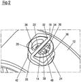
- the spring means 18 is bent in a sigmoidal manner, so that two spring arms 20 are aligned with their ends at least approximately at right angles to a connecting section 32 connecting the spring arms 20.
- the connecting section 32 is received in a recess in the form of a groove 34 of the bearing housing 26, and the spring arms 20 are each inserted through recesses in the form of bores 36 in the bearing housing 26, so that the spring means 18 as a whole is clamped to the bearing housing 26 and in relation is axially biased on the axis of rotation A.
- the spring arms 20 are aligned axially symmetrically with respect to the axis of rotation A of the valve shaft 14 ( Fig. 2 ).
- the extension 22 of the valve device formed on the valve shaft 14 has two opposite flat long sides 38 which define a longitudinal extension of the extension 22 oriented at right angles to the axis of rotation A of the valve shaft 14.
- the extension 22 has two opposite, slightly outwardly curved short sides 40.
- the long sides 38 of the extension 22 or its longitudinal extent are also aligned at least approximately at right angles to a flap plane in which the flap 10 is located.
- the spring arms 20 are aligned in this position at least approximately parallel to the longitudinal extent of the extension 22 and are not supported on the extension 22.
- the spring arms 20 only come into engagement with the extension 22 when the flap 10 is rotated into its closed position, so as to do so to prevent or at least dampen an oscillating movement of the valve shaft 14 or the valve 10.
- the spring arms 20 are partially or selectively supported on the long sides 38 of the extension 22, so that the spring means 18 loads the flap shaft 14 axially symmetrically with respect to the axis of rotation A.
- the spring arms 20 are supported on diagonally opposite edges between the long sides 38 and the short sides 40 of the extension 22, whereby the spring arms 20 are deflected in the closed position of the flap 10. Since the spring arms 20 are deflected in the closed position of the flap 10, the spring arms 20 are pretensioned in the closed position.
- a spring force of the spring means 18 acts on the flap shaft 14 in the radial direction with respect to the axis of rotation A of the flap shaft 14.
- FIGS 3 and 4 show a second embodiment of a flap device, which differs from the first embodiment in that the spring means 18 is designed in the form of a sleeve-like stamped and bent part and comprises a base body 41 which surrounds the bearing housing 26 in a ring-shaped form and / or non-positive fit and from which two spring arms 20 are worked out.
- the spring means 18 is accordingly placed on the bearing housing 26.
- the flap device according to the second embodiment differs from the flap device according to the first embodiment in that in the closed position of the flap 10, the spring arms 20 are each supported on opposite long sides 38 of the extension 22, whereby the spring arms 20 are deflected in the closed position of the flap 10 and are prestressed.
- the respective longitudinal extensions of the spring arms 20 in the open position of the flap 10 are at least approximately at right angles to the longitudinal extension of the extension 22 ( Figures 3 and 4 ), but parallel in the closed position.
- the spring means 18 additionally acts on the flap shaft 14 with a spring force acting in a tangential direction with respect to the axis of rotation A of the flap shaft 14 when the flap shaft 14 and the spring means 18 engage.
- the flap device according to the third embodiment comprises a spring means 18 which is already in engagement with the extension 22 of the flap shaft 14 in the open position of the flap 10 ( Fig. 5 ).
- the spring means 18 of the flap device according to the third embodiment is made from a wire-shaped spring steel and is bent in a heart shape.
- a connecting section 32 which connects two spring arms 20 to one another, is bent in such a way that the connecting section 32 has the same or at least approximately the same curvature as an outer wall 42 of a bearing housing 26 for supporting a bearing 24 supporting the flap shaft 14 Connecting section 32 on the outer wall 42 of the bearing housing 26.
- the ends of the two spring arms 20 point in the direction of the connecting section 32 and are pushed through bores 36 in the bearing housing 26, as a result of which the spring means 18 is clamped to the bearing housing 26.
- the connecting section 32 of the spring means 18 has the same or at least approximately the same curvature as an outer wall 42 of the bearing housing 26, it is advantageous if a contact area between the connecting section 32 of the spring means 18 and the outer wall 42 of the bearing housing is as small as possible in order to keep heat transfer from the bearing housing 26 to the spring means 18 as low as possible.
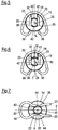
- the extension 22 of the flap device according to this third embodiment has two opposite long sides 38 curved radially outward with respect to the axis of rotation A of the flap shaft 14 and two opposite short sides 40 curved radially outward with respect to the axis of rotation A of the flap shaft 14, so that the extension 22 has an elliptical cross-section with a long axis and a short axis.
- the respective longitudinal extensions of the spring arms 20 are aligned at least approximately parallel to the long axis of the extension 22 in the open position of the flap 10.
- the two spring arms 20 are aligned mirror-symmetrically to a center plane E containing the axis of rotation A of the flap shaft 14, which in the open position of the flap 10 is at least approximately parallel to the longitudinal extension of the extension 22 and which receives the long axis of the extension 22 ( Fig. 5 ).
- the central plane E is aligned at least approximately parallel to the short axis of the extension ( Fig. 6 ).
- the two spring arms 20 are in the closed position of the flap 10 ( Fig. 6 ) further deflected and thus more pretensioned than in the open position of flap 10 ( Fig. 5 ).
- the two spring arms 20 are spread apart in the closed position of the flap 10.
- the spring means 18 therefore loads the flap shaft 14 mirror-symmetrically both in the open position and in the closed position of the flap 10.
- the spring means 18 acts on the flap shaft 14 with a spring force acting in the radial direction with respect to the axis of rotation A of the flap shaft 14.
- Fig. 7 shows a spring means 18 and an extension 22 of a flap device according to a fourth embodiment, which is similar to the flap device according to the third embodiment.
- the flap device according to the fourth embodiment differs from the flap device according to the third embodiment in particular in the way in which the spring means 18 is bent.
- the spring means 18 of the flap device according to the fourth embodiment is bent in the shape of a split pin, two spring arms 20 pointing away from the connecting section 32.
- the spring arms 20 each have a clamping section 44 which is bent radially inward in relation to the axis of rotation A of the flap shaft 14 in the direction of the extension 22, by means of which the spring arms 20 are supported on the extension 22 already in the open position of the flap 10 ( Fig. 7 ).
- the two spring arms 20 are spread apart against their respective spring forces, so that the spring arms 20 are more strongly pretensioned in the closed position of the flap 10 than in the open position of the flap 10 .
- a spring force of the spring means 18 acts in the radial direction with respect to the axis of rotation A of the flap shaft 14.
- the spring means 18 loads the flap shaft with respect to this the axis of rotation A is mirror-symmetrical.
- Fig. 8 shows a flap device according to a fifth embodiment.
- the flap device according to the fifth embodiment differs from the flap device according to the first embodiment in that the spring arms 20 are already in engagement with the extension 22 in the open position of the flap 10 stand.
- a spring force of the spring means 18 acts in the radial direction on the flap shaft 14 in relation to its axis of rotation A.
- the extension 22 has no flat long sides 38 but rather outwardly curved long sides 38 as in the flap device according to the third and fourth embodiment of the flap device.
- the respective longitudinal extensions of the spring arms 20 are aligned at least approximately parallel to the longitudinal axis of the extension 22, the spring arms 20 each with their Support the long sides 46 on the long sides 38 of the extension.
- the spring arms 20 are deflected at least approximately at right angles to their longitudinal extensions against a first spring force in the radial direction with respect to the axis of rotation A of the valve shaft 14, so that the spring means 18 loads the valve shaft 14 axially symmetrically with respect to the axis of rotation A.
- the spring arms 20 are each deflected in the direction of their longitudinal extensions against the spring force of the arched section 45 and generate a second spring force in the tangential direction the axis of rotation A of the valve shaft 14 is deflected.
- the spring arms 20 are each supported with their end faces 50 on the long sides 38 of the extension 22, and the spring arms 20 are at least partially pressed out of the bores 36.
- Figs. 9-11 show a flap device according to a sixth embodiment, which functions similarly to the flap device according to the fifth embodiment in terms of its operating principle.
- the flap device according to the sixth embodiment differs from the flap device according to the fifth embodiment in the design of the extension 22.
- the extension 22 of the flap device of the sixth embodiment has two opposite long sides 38, each long side 38 having two flat wing sections 48, which one Surrounding the radially outwardly curved intermediate section 52 in the direction of the longitudinal extent of the extension 22.
- the spring arms 20 are supported in the open position of the flap 10 each on the curved intermediate section 52 of the extension 22, the spring arms 20 against their first spring force in relation to the axis of rotation A of the flap shaft 14 in a radial Direction are deflected.
- a spring force of the spring means 18 acts in the radial direction on the flap shaft 14 in relation to its axis of rotation A. If the flap shaft 14 is rotated from the open position of the flap 10 to the closed position of the flap 10, the end face 50 of the spring arms 20 come into engagement with the flat wing sections 48 of the extension 22 ( Fig. 10 ), so that the extension 22 presses the spring arms 20 out of the bearing housing 26 against the spring force of the curved section 45, so that the spring arms 20 exert a spring force in the tangential direction in relation to the axis of rotation A of the flap shaft 14.
- FIGS 12 and 13 show a seventh embodiment of the flap device.
- the flap device according to the seventh embodiment has only one spring arm 20, which is bent from a wire-shaped spring steel and attached to the Bearing housing 26 is clamped. In principle, however, more than just one spring arm 20 can also be provided.
- the extension 22 of the flap device according to the seventh embodiment has a circular cross-section, the extension 22 being eccentrically aligned with respect to the axis of rotation A of the flap shaft 14. Due to the eccentric alignment of the extension 22, the extension 22 runs out of the open position when the flap 10 is rotated ( Fig. 12 ) into the closed position on the spring arm 20 and deflects it against its spring force, so that the spring arm 20 is biased at the latest in the closed position of the flap 10. In other words, the spring arm 20 presses in the closed position of the flap 10 against the flap shaft 14 and prevents or at least reduces a vibrational movement of the flap shaft 14 or the flap 10.
- the spring means 18 acts on the flap shaft 14 with a relative to the axis of rotation A of the Flap shaft 14 acting in the radial direction spring force.
Landscapes
- Engineering & Computer Science (AREA)
- General Engineering & Computer Science (AREA)
- Mechanical Engineering (AREA)
- Chemical & Material Sciences (AREA)
- Combustion & Propulsion (AREA)
- Lift Valve (AREA)
- Closing And Opening Devices For Wings, And Checks For Wings (AREA)
- Exhaust Silencers (AREA)
Applications Claiming Priority (1)
| Application Number | Priority Date | Filing Date | Title |
|---|---|---|---|
| DE102019104018.3A DE102019104018A1 (de) | 2019-02-18 | 2019-02-18 | Klappeneinrichtung |
Publications (3)
| Publication Number | Publication Date |
|---|---|
| EP3699416A1 true EP3699416A1 (fr) | 2020-08-26 |
| EP3699416B1 EP3699416B1 (fr) | 2025-04-09 |
| EP3699416C0 EP3699416C0 (fr) | 2025-04-09 |
Family
ID=69701078
Family Applications (1)
| Application Number | Title | Priority Date | Filing Date |
|---|---|---|---|
| EP20157934.9A Active EP3699416B1 (fr) | 2019-02-18 | 2020-02-18 | Dispositif formant clapet |
Country Status (4)
| Country | Link |
|---|---|
| US (1) | US11220982B2 (fr) |
| EP (1) | EP3699416B1 (fr) |
| CN (1) | CN111577436A (fr) |
| DE (1) | DE102019104018A1 (fr) |
Families Citing this family (2)
| Publication number | Priority date | Publication date | Assignee | Title |
|---|---|---|---|---|
| US12320311B2 (en) * | 2022-10-06 | 2025-06-03 | Mikuni Corporation | Valve device |
| US12392309B2 (en) | 2023-02-17 | 2025-08-19 | Power Packer North America, Inc. | Exhaust gas recirculation valve assembly |
Citations (5)
| Publication number | Priority date | Publication date | Assignee | Title |
|---|---|---|---|---|
| JPH02256837A (ja) * | 1988-12-14 | 1990-10-17 | Yamaha Motor Co Ltd | エンジンの排気制御装置 |
| US20080011269A1 (en) * | 2006-07-14 | 2008-01-17 | Denso Corporation | Throttle control apparatus |
| DE102009013815A1 (de) * | 2009-03-18 | 2010-09-23 | Friedrich Boysen Gmbh & Co. Kg | Klappeneinrichtung |
| CN202431374U (zh) * | 2011-11-29 | 2012-09-12 | 长城汽车股份有限公司 | 排气背压阀 |
| DE102015221953A1 (de) * | 2015-11-09 | 2017-05-11 | smk systeme metall kunststoff gmbh & co. kg | Abgasklappenanordnung mit geräuschoptimiertem Radialgleitlager |
Family Cites Families (25)
| Publication number | Priority date | Publication date | Assignee | Title |
|---|---|---|---|---|
| EP0141944B1 (fr) * | 1983-08-31 | 1988-11-17 | Viessmann Werke GmbH & Co. | Dispositif de réglage de tirage de cheminée |
| US4645180A (en) * | 1984-06-15 | 1987-02-24 | Jamesbury Corporation | Wire form type insert retainer for a wafer style butterfly valve |
| DE4028931A1 (de) * | 1990-09-12 | 1992-03-19 | Bosch Gmbh Robert | Drehstellungsgeber |
| US5492097A (en) * | 1994-09-30 | 1996-02-20 | General Motors Corporation | Throttle body default actuation |
| US6193214B1 (en) * | 1996-09-10 | 2001-02-27 | Schatz Thermo System Gmbh | Shut-off or throttle valve with pivotal flap |
| DE10202096A1 (de) * | 2002-01-21 | 2003-07-24 | Siemens Ag | Drosselklappenstutzen |
| DE20211815U1 (de) * | 2002-07-31 | 2002-11-28 | Ab Elektronik Gmbh, 59368 Werne | Luftklappensystem mit Flachband-Gegenfederelement |
| US7051707B2 (en) * | 2003-03-07 | 2006-05-30 | Denso Corporation | Electronically controlled throttle control apparatus |
| US6932100B2 (en) * | 2003-05-23 | 2005-08-23 | Eaton Corporation | Flapper type fill tube check valve |
| JP4575172B2 (ja) * | 2005-01-04 | 2010-11-04 | 中央発條株式会社 | 排気流路制御弁 |
| EP1739286A1 (fr) * | 2005-06-30 | 2007-01-03 | Muhr und Bender KG | Cuvette butée de ressort de soupape avec deux éléments d'appui |
| FR2906334B1 (fr) * | 2006-09-25 | 2011-04-15 | Mark Iv Systemes Moteurs Sa | Unite de vanne a boisseau coulissant et circuit comprenant une telle vanne |
| DE102006048616B4 (de) * | 2006-10-13 | 2020-09-03 | Emcon Technologies Germany (Augsburg) Gmbh | Ventilvorrichtung |
| WO2008107107A1 (fr) * | 2007-03-02 | 2008-09-12 | Elringklinger Ag | Soupape de retenue pour gaz de combustion |
| DE202007006463U1 (de) * | 2007-05-03 | 2008-09-11 | Capristo, Antonio | Drosselklappe und damit ausgestattete Auspuffanlage |
| DE102009014140A1 (de) * | 2009-03-24 | 2010-10-07 | Mtu Friedrichshafen Gmbh | Klappenanordnung, insbesondere Abgasklappenanordnung |
| DE102009016597C5 (de) * | 2009-04-08 | 2023-03-23 | Küster Holding GmbH | Abgasklappenantrieb für ein Kraftfahrzeug |
| JP5180170B2 (ja) * | 2009-09-09 | 2013-04-10 | 愛三工業株式会社 | 電子制御式スロットル制御装置 |
| JP6435486B2 (ja) * | 2014-09-24 | 2018-12-12 | 株式会社テージーケー | 制御弁 |
| US10344879B2 (en) * | 2014-09-26 | 2019-07-09 | Piolax, Inc. | Flap valve apparatus |
| JP6368895B2 (ja) * | 2014-10-01 | 2018-08-08 | 株式会社テージーケー | 制御弁 |
| DE102016111681A1 (de) * | 2016-06-27 | 2017-12-28 | Eberspächer Exhaust Technology GmbH & Co. KG | Abgasklappe |
| DE102016114703A1 (de) * | 2016-06-28 | 2017-12-28 | Eberspächer Exhaust Technology GmbH & Co. KG | Kopplungsanordnung zur Drehkopplung einer Schwenkwelle einer Klappenblende einer Abgasklappe mit einem Antriebsorgan |
| US9982793B2 (en) * | 2016-08-05 | 2018-05-29 | Tenneco Automotive Operating Company Inc. | Passive exhaust valve with dual torsion spring |
| DE102020103420A1 (de) * | 2020-02-11 | 2021-08-12 | Friedrich Boysen GmbH & Co KG. | Klappeneinrichtung |
-
2019
- 2019-02-18 DE DE102019104018.3A patent/DE102019104018A1/de not_active Withdrawn
-
2020
- 2020-02-12 CN CN202010087938.7A patent/CN111577436A/zh active Pending
- 2020-02-18 US US16/793,095 patent/US11220982B2/en active Active
- 2020-02-18 EP EP20157934.9A patent/EP3699416B1/fr active Active
Patent Citations (5)
| Publication number | Priority date | Publication date | Assignee | Title |
|---|---|---|---|---|
| JPH02256837A (ja) * | 1988-12-14 | 1990-10-17 | Yamaha Motor Co Ltd | エンジンの排気制御装置 |
| US20080011269A1 (en) * | 2006-07-14 | 2008-01-17 | Denso Corporation | Throttle control apparatus |
| DE102009013815A1 (de) * | 2009-03-18 | 2010-09-23 | Friedrich Boysen Gmbh & Co. Kg | Klappeneinrichtung |
| CN202431374U (zh) * | 2011-11-29 | 2012-09-12 | 长城汽车股份有限公司 | 排气背压阀 |
| DE102015221953A1 (de) * | 2015-11-09 | 2017-05-11 | smk systeme metall kunststoff gmbh & co. kg | Abgasklappenanordnung mit geräuschoptimiertem Radialgleitlager |
Also Published As
| Publication number | Publication date |
|---|---|
| DE102019104018A1 (de) | 2020-08-20 |
| US20200263640A1 (en) | 2020-08-20 |
| CN111577436A (zh) | 2020-08-25 |
| EP3699416B1 (fr) | 2025-04-09 |
| EP3699416C0 (fr) | 2025-04-09 |
| US11220982B2 (en) | 2022-01-11 |
Similar Documents
| Publication | Publication Date | Title |
|---|---|---|
| EP3431815B1 (fr) | Dispositif de tension de courroie | |
| DE102013102562B4 (de) | Verwendung einer Feder in einer Riemenspannvorrichtung, Riemenspannvorrichtung und Aggregatanordnung | |
| EP3099527B1 (fr) | Actionneur pour un véhicule automobile, notamment pour un siège de véhicule automobile | |
| DE10334906B4 (de) | Antivibrationselement | |
| EP1585912B1 (fr) | Unite modulaire munie d'un manchon pour transmission par chaine | |
| EP2494181B1 (fr) | Dispositif de transport de carburant | |
| DE112013007465T5 (de) | Zylindrische vibrationsdämpfende Vorrichtung | |
| DE102018000070A1 (de) | Fliehkraftpendelvorrichtung und Torsionsschwingungsdämpfer mit einer solchen Fliehkraftpendelvorrichtung | |
| EP3091188A1 (fr) | Turbomachine dotée d'un dispositif d'étanchéité | |
| EP1778988B1 (fr) | Joint spherique | |
| EP3699416B1 (fr) | Dispositif formant clapet | |
| WO2002020996A1 (fr) | Dispositif de fixation destine a un silencieux a filtre se trouvant a l'entree du compresseur d'un turbocompresseur | |
| WO2016188643A1 (fr) | Compresseur à réfrigérant | |
| DE102015217911A1 (de) | Kolben für eine Brennkraftmaschine | |
| WO2023147947A1 (fr) | Ensemble ayant un corps à base d'élastomère | |
| DE10312977A1 (de) | Federelement | |
| DE102017119783B4 (de) | Verbindungsstange mit Dämpfungseinrichtung eines Verbrennungsmotors | |
| DE102008036647A1 (de) | Taumelgelenkbeschlag für einen Kraftfahrzeugsitz | |
| DE10322250B4 (de) | System mit Hilfsnockenwelle und mindestens zwei Lagern und Verfahren zur Herstellung eines Systems mit Hilfsnockenwelle und mindestens zwei Lagern | |
| DE102012107857B4 (de) | Lagerbuchse | |
| DE102005052453A1 (de) | Spanneinrichtung für ein Zugmittel, insbesondere einen Riemen | |
| DE19744796C2 (de) | Gelenk, insbesondere für eine blockierbare Gasfeder | |
| DE102019208531A1 (de) | Kraftfahrzeugschwingungsdämpfer | |
| EP2138730A2 (fr) | Coussinet et palier | |
| EP1571366B1 (fr) | Support élastique |
Legal Events
| Date | Code | Title | Description |
|---|---|---|---|
| PUAI | Public reference made under article 153(3) epc to a published international application that has entered the european phase |
Free format text: ORIGINAL CODE: 0009012 |
|
| STAA | Information on the status of an ep patent application or granted ep patent |
Free format text: STATUS: THE APPLICATION HAS BEEN PUBLISHED |
|
| AK | Designated contracting states |
Kind code of ref document: A1 Designated state(s): AL AT BE BG CH CY CZ DE DK EE ES FI FR GB GR HR HU IE IS IT LI LT LU LV MC MK MT NL NO PL PT RO RS SE SI SK SM TR |
|
| AX | Request for extension of the european patent |
Extension state: BA ME |
|
| STAA | Information on the status of an ep patent application or granted ep patent |
Free format text: STATUS: REQUEST FOR EXAMINATION WAS MADE |
|
| 17P | Request for examination filed |
Effective date: 20210223 |
|
| RBV | Designated contracting states (corrected) |
Designated state(s): AL AT BE BG CH CY CZ DE DK EE ES FI FR GB GR HR HU IE IS IT LI LT LU LV MC MK MT NL NO PL PT RO RS SE SI SK SM TR |
|
| STAA | Information on the status of an ep patent application or granted ep patent |
Free format text: STATUS: EXAMINATION IS IN PROGRESS |
|
| 17Q | First examination report despatched |
Effective date: 20221116 |
|
| GRAP | Despatch of communication of intention to grant a patent |
Free format text: ORIGINAL CODE: EPIDOSNIGR1 |
|
| STAA | Information on the status of an ep patent application or granted ep patent |
Free format text: STATUS: GRANT OF PATENT IS INTENDED |
|
| INTG | Intention to grant announced |
Effective date: 20241119 |
|
| GRAS | Grant fee paid |
Free format text: ORIGINAL CODE: EPIDOSNIGR3 |
|
| GRAA | (expected) grant |
Free format text: ORIGINAL CODE: 0009210 |
|
| STAA | Information on the status of an ep patent application or granted ep patent |
Free format text: STATUS: THE PATENT HAS BEEN GRANTED |
|
| AK | Designated contracting states |
Kind code of ref document: B1 Designated state(s): AL AT BE BG CH CY CZ DE DK EE ES FI FR GB GR HR HU IE IS IT LI LT LU LV MC MK MT NL NO PL PT RO RS SE SI SK SM TR |
|
| REG | Reference to a national code |
Ref country code: GB Ref legal event code: FG4D Free format text: NOT ENGLISH |
|
| REG | Reference to a national code |
Ref country code: CH Ref legal event code: EP |
|
| REG | Reference to a national code |
Ref country code: IE Ref legal event code: FG4D Free format text: LANGUAGE OF EP DOCUMENT: GERMAN |
|
| U01 | Request for unitary effect filed |
Effective date: 20250409 |
|
| U07 | Unitary effect registered |
Designated state(s): AT BE BG DE DK EE FI FR IT LT LU LV MT NL PT RO SE SI Effective date: 20250415 |
|
| PG25 | Lapsed in a contracting state [announced via postgrant information from national office to epo] |
Ref country code: ES Free format text: LAPSE BECAUSE OF FAILURE TO SUBMIT A TRANSLATION OF THE DESCRIPTION OR TO PAY THE FEE WITHIN THE PRESCRIBED TIME-LIMIT Effective date: 20250409 |
|
| PG25 | Lapsed in a contracting state [announced via postgrant information from national office to epo] |
Ref country code: NO Free format text: LAPSE BECAUSE OF FAILURE TO SUBMIT A TRANSLATION OF THE DESCRIPTION OR TO PAY THE FEE WITHIN THE PRESCRIBED TIME-LIMIT Effective date: 20250709 Ref country code: GR Free format text: LAPSE BECAUSE OF FAILURE TO SUBMIT A TRANSLATION OF THE DESCRIPTION OR TO PAY THE FEE WITHIN THE PRESCRIBED TIME-LIMIT Effective date: 20250710 |
|
| PG25 | Lapsed in a contracting state [announced via postgrant information from national office to epo] |
Ref country code: PL Free format text: LAPSE BECAUSE OF FAILURE TO SUBMIT A TRANSLATION OF THE DESCRIPTION OR TO PAY THE FEE WITHIN THE PRESCRIBED TIME-LIMIT Effective date: 20250409 |
|
| PG25 | Lapsed in a contracting state [announced via postgrant information from national office to epo] |
Ref country code: HR Free format text: LAPSE BECAUSE OF FAILURE TO SUBMIT A TRANSLATION OF THE DESCRIPTION OR TO PAY THE FEE WITHIN THE PRESCRIBED TIME-LIMIT Effective date: 20250409 |
|
| PG25 | Lapsed in a contracting state [announced via postgrant information from national office to epo] |
Ref country code: RS Free format text: LAPSE BECAUSE OF FAILURE TO SUBMIT A TRANSLATION OF THE DESCRIPTION OR TO PAY THE FEE WITHIN THE PRESCRIBED TIME-LIMIT Effective date: 20250709 |
|
| PG25 | Lapsed in a contracting state [announced via postgrant information from national office to epo] |
Ref country code: IS Free format text: LAPSE BECAUSE OF FAILURE TO SUBMIT A TRANSLATION OF THE DESCRIPTION OR TO PAY THE FEE WITHIN THE PRESCRIBED TIME-LIMIT Effective date: 20250809 |
|
| PG25 | Lapsed in a contracting state [announced via postgrant information from national office to epo] |
Ref country code: SM Free format text: LAPSE BECAUSE OF FAILURE TO SUBMIT A TRANSLATION OF THE DESCRIPTION OR TO PAY THE FEE WITHIN THE PRESCRIBED TIME-LIMIT Effective date: 20250409 |
|
| PG25 | Lapsed in a contracting state [announced via postgrant information from national office to epo] |
Ref country code: CZ Free format text: LAPSE BECAUSE OF FAILURE TO SUBMIT A TRANSLATION OF THE DESCRIPTION OR TO PAY THE FEE WITHIN THE PRESCRIBED TIME-LIMIT Effective date: 20250409 |
|
| PG25 | Lapsed in a contracting state [announced via postgrant information from national office to epo] |
Ref country code: SK Free format text: LAPSE BECAUSE OF FAILURE TO SUBMIT A TRANSLATION OF THE DESCRIPTION OR TO PAY THE FEE WITHIN THE PRESCRIBED TIME-LIMIT Effective date: 20250409 |
|
| PLBE | No opposition filed within time limit |
Free format text: ORIGINAL CODE: 0009261 |
|
| STAA | Information on the status of an ep patent application or granted ep patent |
Free format text: STATUS: NO OPPOSITION FILED WITHIN TIME LIMIT |
|
| REG | Reference to a national code |
Ref country code: CH Ref legal event code: L10 Free format text: ST27 STATUS EVENT CODE: U-0-0-L10-L00 (AS PROVIDED BY THE NATIONAL OFFICE) Effective date: 20260218 |
|
| 26N | No opposition filed |
Effective date: 20260112 |
|
| U20 | Renewal fee for the european patent with unitary effect paid |
Year of fee payment: 7 Effective date: 20260227 |