EP3699480B1 - System, fülladapter für medizinische gase und aktivierungswelle zur verwendung in einem solchen system - Google Patents
System, fülladapter für medizinische gase und aktivierungswelle zur verwendung in einem solchen system Download PDFInfo
- Publication number
- EP3699480B1 EP3699480B1 EP20159307.6A EP20159307A EP3699480B1 EP 3699480 B1 EP3699480 B1 EP 3699480B1 EP 20159307 A EP20159307 A EP 20159307A EP 3699480 B1 EP3699480 B1 EP 3699480B1
- Authority
- EP
- European Patent Office
- Prior art keywords
- valve
- adapter
- return valve
- vipr
- shaft
- Prior art date
- Legal status (The legal status is an assumption and is not a legal conclusion. Google has not performed a legal analysis and makes no representation as to the accuracy of the status listed.)
- Active
Links
Images


Classifications
-
- F—MECHANICAL ENGINEERING; LIGHTING; HEATING; WEAPONS; BLASTING
- F17—STORING OR DISTRIBUTING GASES OR LIQUIDS
- F17C—VESSELS FOR CONTAINING OR STORING COMPRESSED, LIQUEFIED OR SOLIDIFIED GASES; FIXED-CAPACITY GAS-HOLDERS; FILLING VESSELS WITH, OR DISCHARGING FROM VESSELS, COMPRESSED, LIQUEFIED, OR SOLIDIFIED GASES
- F17C5/00—Methods or apparatus for filling containers with liquefied, solidified, or compressed gases under pressures
-
- F—MECHANICAL ENGINEERING; LIGHTING; HEATING; WEAPONS; BLASTING
- F17—STORING OR DISTRIBUTING GASES OR LIQUIDS
- F17C—VESSELS FOR CONTAINING OR STORING COMPRESSED, LIQUEFIED OR SOLIDIFIED GASES; FIXED-CAPACITY GAS-HOLDERS; FILLING VESSELS WITH, OR DISCHARGING FROM VESSELS, COMPRESSED, LIQUEFIED, OR SOLIDIFIED GASES
- F17C13/00—Details of vessels or of the filling or discharging of vessels
- F17C13/04—Arrangement or mounting of valves
-
- F—MECHANICAL ENGINEERING; LIGHTING; HEATING; WEAPONS; BLASTING
- F17—STORING OR DISTRIBUTING GASES OR LIQUIDS
- F17C—VESSELS FOR CONTAINING OR STORING COMPRESSED, LIQUEFIED OR SOLIDIFIED GASES; FIXED-CAPACITY GAS-HOLDERS; FILLING VESSELS WITH, OR DISCHARGING FROM VESSELS, COMPRESSED, LIQUEFIED, OR SOLIDIFIED GASES
- F17C1/00—Pressure vessels, e.g. gas cylinder, gas tank, replaceable cartridge
-
- F—MECHANICAL ENGINEERING; LIGHTING; HEATING; WEAPONS; BLASTING
- F17—STORING OR DISTRIBUTING GASES OR LIQUIDS
- F17C—VESSELS FOR CONTAINING OR STORING COMPRESSED, LIQUEFIED OR SOLIDIFIED GASES; FIXED-CAPACITY GAS-HOLDERS; FILLING VESSELS WITH, OR DISCHARGING FROM VESSELS, COMPRESSED, LIQUEFIED, OR SOLIDIFIED GASES
- F17C2201/00—Vessel construction, in particular geometry, arrangement or size
- F17C2201/01—Shape
- F17C2201/0104—Shape cylindrical
- F17C2201/0109—Shape cylindrical with exteriorly curved end-piece
-
- F—MECHANICAL ENGINEERING; LIGHTING; HEATING; WEAPONS; BLASTING
- F17—STORING OR DISTRIBUTING GASES OR LIQUIDS
- F17C—VESSELS FOR CONTAINING OR STORING COMPRESSED, LIQUEFIED OR SOLIDIFIED GASES; FIXED-CAPACITY GAS-HOLDERS; FILLING VESSELS WITH, OR DISCHARGING FROM VESSELS, COMPRESSED, LIQUEFIED, OR SOLIDIFIED GASES
- F17C2201/00—Vessel construction, in particular geometry, arrangement or size
- F17C2201/03—Orientation
- F17C2201/032—Orientation with substantially vertical main axis
-
- F—MECHANICAL ENGINEERING; LIGHTING; HEATING; WEAPONS; BLASTING
- F17—STORING OR DISTRIBUTING GASES OR LIQUIDS
- F17C—VESSELS FOR CONTAINING OR STORING COMPRESSED, LIQUEFIED OR SOLIDIFIED GASES; FIXED-CAPACITY GAS-HOLDERS; FILLING VESSELS WITH, OR DISCHARGING FROM VESSELS, COMPRESSED, LIQUEFIED, OR SOLIDIFIED GASES
- F17C2201/00—Vessel construction, in particular geometry, arrangement or size
- F17C2201/05—Size
- F17C2201/056—Small (<1 m3)
-
- F—MECHANICAL ENGINEERING; LIGHTING; HEATING; WEAPONS; BLASTING
- F17—STORING OR DISTRIBUTING GASES OR LIQUIDS
- F17C—VESSELS FOR CONTAINING OR STORING COMPRESSED, LIQUEFIED OR SOLIDIFIED GASES; FIXED-CAPACITY GAS-HOLDERS; FILLING VESSELS WITH, OR DISCHARGING FROM VESSELS, COMPRESSED, LIQUEFIED, OR SOLIDIFIED GASES
- F17C2201/00—Vessel construction, in particular geometry, arrangement or size
- F17C2201/05—Size
- F17C2201/058—Size portable (<30 l)
-
- F—MECHANICAL ENGINEERING; LIGHTING; HEATING; WEAPONS; BLASTING
- F17—STORING OR DISTRIBUTING GASES OR LIQUIDS
- F17C—VESSELS FOR CONTAINING OR STORING COMPRESSED, LIQUEFIED OR SOLIDIFIED GASES; FIXED-CAPACITY GAS-HOLDERS; FILLING VESSELS WITH, OR DISCHARGING FROM VESSELS, COMPRESSED, LIQUEFIED, OR SOLIDIFIED GASES
- F17C2205/00—Vessel construction, in particular mounting arrangements, attachments or identifications means
- F17C2205/03—Fluid connections, filters, valves, closure means or other attachments
- F17C2205/0302—Fittings, valves, filters, or components in connection with the gas storage device
- F17C2205/0323—Valves
-
- F—MECHANICAL ENGINEERING; LIGHTING; HEATING; WEAPONS; BLASTING
- F17—STORING OR DISTRIBUTING GASES OR LIQUIDS
- F17C—VESSELS FOR CONTAINING OR STORING COMPRESSED, LIQUEFIED OR SOLIDIFIED GASES; FIXED-CAPACITY GAS-HOLDERS; FILLING VESSELS WITH, OR DISCHARGING FROM VESSELS, COMPRESSED, LIQUEFIED, OR SOLIDIFIED GASES
- F17C2205/00—Vessel construction, in particular mounting arrangements, attachments or identifications means
- F17C2205/03—Fluid connections, filters, valves, closure means or other attachments
- F17C2205/0302—Fittings, valves, filters, or components in connection with the gas storage device
- F17C2205/0323—Valves
- F17C2205/0329—Valves manually actuated
-
- F—MECHANICAL ENGINEERING; LIGHTING; HEATING; WEAPONS; BLASTING
- F17—STORING OR DISTRIBUTING GASES OR LIQUIDS
- F17C—VESSELS FOR CONTAINING OR STORING COMPRESSED, LIQUEFIED OR SOLIDIFIED GASES; FIXED-CAPACITY GAS-HOLDERS; FILLING VESSELS WITH, OR DISCHARGING FROM VESSELS, COMPRESSED, LIQUEFIED, OR SOLIDIFIED GASES
- F17C2205/00—Vessel construction, in particular mounting arrangements, attachments or identifications means
- F17C2205/03—Fluid connections, filters, valves, closure means or other attachments
- F17C2205/0302—Fittings, valves, filters, or components in connection with the gas storage device
- F17C2205/0323—Valves
- F17C2205/0335—Check-valves or non-return valves
-
- F—MECHANICAL ENGINEERING; LIGHTING; HEATING; WEAPONS; BLASTING
- F17—STORING OR DISTRIBUTING GASES OR LIQUIDS
- F17C—VESSELS FOR CONTAINING OR STORING COMPRESSED, LIQUEFIED OR SOLIDIFIED GASES; FIXED-CAPACITY GAS-HOLDERS; FILLING VESSELS WITH, OR DISCHARGING FROM VESSELS, COMPRESSED, LIQUEFIED, OR SOLIDIFIED GASES
- F17C2205/00—Vessel construction, in particular mounting arrangements, attachments or identifications means
- F17C2205/03—Fluid connections, filters, valves, closure means or other attachments
- F17C2205/0302—Fittings, valves, filters, or components in connection with the gas storage device
- F17C2205/0338—Pressure regulators
-
- F—MECHANICAL ENGINEERING; LIGHTING; HEATING; WEAPONS; BLASTING
- F17—STORING OR DISTRIBUTING GASES OR LIQUIDS
- F17C—VESSELS FOR CONTAINING OR STORING COMPRESSED, LIQUEFIED OR SOLIDIFIED GASES; FIXED-CAPACITY GAS-HOLDERS; FILLING VESSELS WITH, OR DISCHARGING FROM VESSELS, COMPRESSED, LIQUEFIED, OR SOLIDIFIED GASES
- F17C2205/00—Vessel construction, in particular mounting arrangements, attachments or identifications means
- F17C2205/03—Fluid connections, filters, valves, closure means or other attachments
- F17C2205/0302—Fittings, valves, filters, or components in connection with the gas storage device
- F17C2205/037—Quick connecting means, e.g. couplings
- F17C2205/0373—Adapters
-
- F—MECHANICAL ENGINEERING; LIGHTING; HEATING; WEAPONS; BLASTING
- F17—STORING OR DISTRIBUTING GASES OR LIQUIDS
- F17C—VESSELS FOR CONTAINING OR STORING COMPRESSED, LIQUEFIED OR SOLIDIFIED GASES; FIXED-CAPACITY GAS-HOLDERS; FILLING VESSELS WITH, OR DISCHARGING FROM VESSELS, COMPRESSED, LIQUEFIED, OR SOLIDIFIED GASES
- F17C2205/00—Vessel construction, in particular mounting arrangements, attachments or identifications means
- F17C2205/03—Fluid connections, filters, valves, closure means or other attachments
- F17C2205/0302—Fittings, valves, filters, or components in connection with the gas storage device
- F17C2205/0382—Constructional details of valves, regulators
- F17C2205/0385—Constructional details of valves, regulators in blocks or units
-
- F—MECHANICAL ENGINEERING; LIGHTING; HEATING; WEAPONS; BLASTING
- F17—STORING OR DISTRIBUTING GASES OR LIQUIDS
- F17C—VESSELS FOR CONTAINING OR STORING COMPRESSED, LIQUEFIED OR SOLIDIFIED GASES; FIXED-CAPACITY GAS-HOLDERS; FILLING VESSELS WITH, OR DISCHARGING FROM VESSELS, COMPRESSED, LIQUEFIED, OR SOLIDIFIED GASES
- F17C2221/00—Handled fluid, in particular type of fluid
- F17C2221/01—Pure fluids
- F17C2221/011—Oxygen
-
- F—MECHANICAL ENGINEERING; LIGHTING; HEATING; WEAPONS; BLASTING
- F17—STORING OR DISTRIBUTING GASES OR LIQUIDS
- F17C—VESSELS FOR CONTAINING OR STORING COMPRESSED, LIQUEFIED OR SOLIDIFIED GASES; FIXED-CAPACITY GAS-HOLDERS; FILLING VESSELS WITH, OR DISCHARGING FROM VESSELS, COMPRESSED, LIQUEFIED, OR SOLIDIFIED GASES
- F17C2221/00—Handled fluid, in particular type of fluid
- F17C2221/01—Pure fluids
- F17C2221/013—Carbon dioxide
-
- F—MECHANICAL ENGINEERING; LIGHTING; HEATING; WEAPONS; BLASTING
- F17—STORING OR DISTRIBUTING GASES OR LIQUIDS
- F17C—VESSELS FOR CONTAINING OR STORING COMPRESSED, LIQUEFIED OR SOLIDIFIED GASES; FIXED-CAPACITY GAS-HOLDERS; FILLING VESSELS WITH, OR DISCHARGING FROM VESSELS, COMPRESSED, LIQUEFIED, OR SOLIDIFIED GASES
- F17C2221/00—Handled fluid, in particular type of fluid
- F17C2221/01—Pure fluids
- F17C2221/014—Nitrogen
-
- F—MECHANICAL ENGINEERING; LIGHTING; HEATING; WEAPONS; BLASTING
- F17—STORING OR DISTRIBUTING GASES OR LIQUIDS
- F17C—VESSELS FOR CONTAINING OR STORING COMPRESSED, LIQUEFIED OR SOLIDIFIED GASES; FIXED-CAPACITY GAS-HOLDERS; FILLING VESSELS WITH, OR DISCHARGING FROM VESSELS, COMPRESSED, LIQUEFIED, OR SOLIDIFIED GASES
- F17C2221/00—Handled fluid, in particular type of fluid
- F17C2221/01—Pure fluids
- F17C2221/018—Acetylene
-
- F—MECHANICAL ENGINEERING; LIGHTING; HEATING; WEAPONS; BLASTING
- F17—STORING OR DISTRIBUTING GASES OR LIQUIDS
- F17C—VESSELS FOR CONTAINING OR STORING COMPRESSED, LIQUEFIED OR SOLIDIFIED GASES; FIXED-CAPACITY GAS-HOLDERS; FILLING VESSELS WITH, OR DISCHARGING FROM VESSELS, COMPRESSED, LIQUEFIED, OR SOLIDIFIED GASES
- F17C2223/00—Handled fluid before transfer, i.e. state of fluid when stored in the vessel or before transfer from the vessel
- F17C2223/01—Handled fluid before transfer, i.e. state of fluid when stored in the vessel or before transfer from the vessel characterised by the phase
- F17C2223/0107—Single phase
- F17C2223/0123—Single phase gaseous, e.g. CNG, GNC
-
- F—MECHANICAL ENGINEERING; LIGHTING; HEATING; WEAPONS; BLASTING
- F17—STORING OR DISTRIBUTING GASES OR LIQUIDS
- F17C—VESSELS FOR CONTAINING OR STORING COMPRESSED, LIQUEFIED OR SOLIDIFIED GASES; FIXED-CAPACITY GAS-HOLDERS; FILLING VESSELS WITH, OR DISCHARGING FROM VESSELS, COMPRESSED, LIQUEFIED, OR SOLIDIFIED GASES
- F17C2223/00—Handled fluid before transfer, i.e. state of fluid when stored in the vessel or before transfer from the vessel
- F17C2223/03—Handled fluid before transfer, i.e. state of fluid when stored in the vessel or before transfer from the vessel characterised by the pressure level
- F17C2223/036—Very high pressure (>80 bar)
-
- F—MECHANICAL ENGINEERING; LIGHTING; HEATING; WEAPONS; BLASTING
- F17—STORING OR DISTRIBUTING GASES OR LIQUIDS
- F17C—VESSELS FOR CONTAINING OR STORING COMPRESSED, LIQUEFIED OR SOLIDIFIED GASES; FIXED-CAPACITY GAS-HOLDERS; FILLING VESSELS WITH, OR DISCHARGING FROM VESSELS, COMPRESSED, LIQUEFIED, OR SOLIDIFIED GASES
- F17C2227/00—Transfer of fluids, i.e. method or means for transferring the fluid; Heat exchange with the fluid
- F17C2227/04—Methods for emptying or filling
- F17C2227/041—Methods for emptying or filling vessel by vessel
- F17C2227/042—Methods for emptying or filling vessel by vessel with change-over from one vessel to another
-
- F—MECHANICAL ENGINEERING; LIGHTING; HEATING; WEAPONS; BLASTING
- F17—STORING OR DISTRIBUTING GASES OR LIQUIDS
- F17C—VESSELS FOR CONTAINING OR STORING COMPRESSED, LIQUEFIED OR SOLIDIFIED GASES; FIXED-CAPACITY GAS-HOLDERS; FILLING VESSELS WITH, OR DISCHARGING FROM VESSELS, COMPRESSED, LIQUEFIED, OR SOLIDIFIED GASES
- F17C2227/00—Transfer of fluids, i.e. method or means for transferring the fluid; Heat exchange with the fluid
- F17C2227/04—Methods for emptying or filling
- F17C2227/045—Methods for emptying or filling by vacuum
-
- F—MECHANICAL ENGINEERING; LIGHTING; HEATING; WEAPONS; BLASTING
- F17—STORING OR DISTRIBUTING GASES OR LIQUIDS
- F17C—VESSELS FOR CONTAINING OR STORING COMPRESSED, LIQUEFIED OR SOLIDIFIED GASES; FIXED-CAPACITY GAS-HOLDERS; FILLING VESSELS WITH, OR DISCHARGING FROM VESSELS, COMPRESSED, LIQUEFIED, OR SOLIDIFIED GASES
- F17C2227/00—Transfer of fluids, i.e. method or means for transferring the fluid; Heat exchange with the fluid
- F17C2227/04—Methods for emptying or filling
- F17C2227/048—Methods for emptying or filling by maintaining residual pressure
-
- F—MECHANICAL ENGINEERING; LIGHTING; HEATING; WEAPONS; BLASTING
- F17—STORING OR DISTRIBUTING GASES OR LIQUIDS
- F17C—VESSELS FOR CONTAINING OR STORING COMPRESSED, LIQUEFIED OR SOLIDIFIED GASES; FIXED-CAPACITY GAS-HOLDERS; FILLING VESSELS WITH, OR DISCHARGING FROM VESSELS, COMPRESSED, LIQUEFIED, OR SOLIDIFIED GASES
- F17C2260/00—Purposes of gas storage and gas handling
- F17C2260/04—Reducing risks and environmental impact
- F17C2260/048—Refurbishing
-
- F—MECHANICAL ENGINEERING; LIGHTING; HEATING; WEAPONS; BLASTING
- F17—STORING OR DISTRIBUTING GASES OR LIQUIDS
- F17C—VESSELS FOR CONTAINING OR STORING COMPRESSED, LIQUEFIED OR SOLIDIFIED GASES; FIXED-CAPACITY GAS-HOLDERS; FILLING VESSELS WITH, OR DISCHARGING FROM VESSELS, COMPRESSED, LIQUEFIED, OR SOLIDIFIED GASES
- F17C2270/00—Applications
- F17C2270/02—Applications for medical applications
-
- F—MECHANICAL ENGINEERING; LIGHTING; HEATING; WEAPONS; BLASTING
- F17—STORING OR DISTRIBUTING GASES OR LIQUIDS
- F17C—VESSELS FOR CONTAINING OR STORING COMPRESSED, LIQUEFIED OR SOLIDIFIED GASES; FIXED-CAPACITY GAS-HOLDERS; FILLING VESSELS WITH, OR DISCHARGING FROM VESSELS, COMPRESSED, LIQUEFIED, OR SOLIDIFIED GASES
- F17C2270/00—Applications
- F17C2270/02—Applications for medical applications
- F17C2270/025—Breathing
Definitions
- the present invention relates to a system including pressure cylinder valve with integrated pressure regulator (VIPR) having a VIPR non-return valve and comprising an activation shaft and a medical gas filler adapter for emptying and filling the pressure cylinder, where said medical gas filler adapter comprises integrated adapter non-return valve for use in filling and testing VIPR valve, and a first end and a second end, wherein at least one gas connection is arranged between said first end and said second end.
- VIP pressure cylinder valve with integrated pressure regulator
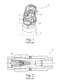
- Gas cylinders for industrial and medical use are typically steel cylinders, aluminium cylinders or composite cylinders that are filled to pressures of 200 or 300 bar.
- the cylinders exist in a number of different sizes from 1 litre up to 80 litres. This means that there is a great variation in diameter and height, and of course weight.
- the heaviest cylinders weigh up to 100 kg, and the lightest down to 1.5 kg.
- the light cylinders are typically those used for medical gases for the reason that they in some situations are carried by the user.
- the number of variants is less for medical gases; the standards describe 9 different types of gases, meaning gases and mixtures of gases.
- the variation in the consumption to be delivered by cylinder and valve is very great. This is due to the fact that patients are very different, as new-born infants, adult males and women require very different dosage of oxygen and anaesthetic gases.
- the issue here is the many different flow settings going from 0.1 l/min up to 25 l/min, with a large number of different settings there between.
- the gas cylinders are filled with gas by the gas companies, and the cylinders are typically distributed to the customers by car and are typically also collected by car.
- a gas company can have a number of filling stations in a country, depending on the size of the country and the number of gas cylinders in use.
- a typical filling station for industrial use fills from 500,000 to 2,000,000 cylinders per year. As an average, an industrial cylinder of 50 liters typically is filled two times a year. Medical cylinders are typically filled four to eight times a year, given that they are somewhat smaller in volume.
- a medical cylinder comprises a valve and a cylinder as well as the contents.
- the content of the cylinder is regarded as a medicament and is covered by rules for medicaments.
- Valve and cylinder are regarded as medical equipment and is to be labelled according to various directives and standards in Europe.
- the modem valves include a valve with shutoff for the cylinder, a pressure regulating unit and a unit for setting various flows.
- the present processes for filling and check of medical gases include:
- DE 102007005864 A1 discloses an activation shaft for use in a prior art medical gas filling system, where this activation shaft at one end has a projecting part configured to engage the non-return valve at the matching end of the filler adapter.
- WO 2017/067556 A1 discloses an automatic gas cylinder filling facility from where a method for filling gas on gas cylinders with pressures greater than 50 bar in an automatic gas cylinder filling facility is known and where the method including at least the following steps:
- the filler adapter When the filler adapter is on the valve, the filler adapter can be connected on all subsequent station and be filled with gas at pressures greater than 50 bar.
- the cylinders are filled one by one in different steps.
- the filler adapters are disposed in the vicinity of the gas cylinder valves such that they can be gripped and screwed into the filler neck of the cylinders. Filler adapters with different connecting threads can therefore be mounted, and since they sit in a holder they can easily be fetched automatically and also be screwed on automatically. After use they are screwed off and placed again in respective holders.
- a filler adapter is mounted automatically with different screw thread depending on national standard for the gas in question.
- the filler adapter is connected with a ball lock that can withstand pressures over 500 bar.
- One of the disadvantages of the prior art filling adapter is that it cannot activate the non-return valve in a VIPR (valve with integrated pressure regulator) due to the fact that it requires a further displacement of the non-return valve in the adapter.
- VIPR valve with integrated pressure regulator
- the object of this invention is to provide a system including pressure cylinder valve with integrated pressure regulator (VIPR) having a VIPR non-return valve and comprising an activation shaft and a medical gas filler adapter of the system type mentioned in the introduction, which makes it possible for filling and testing medical integrated valves, also called VIPR (valve with integrated pressure regulator) with built-in non-return valves in the filling port and where the filler adapter is able to activate the non-return valve in the valve by a further displacement of the non-return valve in the filler adapter.
- VIPR valve with integrated pressure regulator
- the cylinders and valves are used with high pressure oxygen or other medical gases from 200 up to 300 bar.
- An object not covered by the claimed invention is to provide a medical gas filler adapter (hereafter just mentioned as a filler adapter) at an automatic gas cylinder filling facility as the mentioned prior art.
- An object also not covered by the claimed invention is to provide an activation shaft suitable for use in said system, where the activation shaft is able to be connected to the second end of the filler adapter in such way that the actuator shaft decides how large the opening should be to the non-return valve in the VIPR valve. A larger opening is required when emptying and evacuating and a smaller opening when measuring leakage inside the valve.
- This invention is related to a system comprising a medical gas filler adapter that is attached to the fill port in the VIPR.
- the filler adapter makes it possible to connect to the VIPR valve and make a leak tight seal on the fill port. It has a check valve that makes sure that no leak from the cylinder can come out and also prevents contamination to get into the cylinder.
- the gas in a medical cylinder has to be very clean and when filling it has always been a problem that dirt can get into the cylinder.
- the filler adapter makes it further possible to have all the different situations in control.
- the check valve in the filler adapter is so designed that after these processes, its complete gastight under vacuum or high pressure is up to 300 bar. This is achieved by a very unique design of seal and the way it is attached to the piston and protected from the forces working under high flow conditions.
- the above object is achieved with a system of the type mentioned in the preamble of claim 1, where the first end is configured to be connected to the VIPR valve and the second end is configured to be connected to the activation shaft that is able to open the adapter non-return valve; where the adapter non-return valve via a spring is spring-loaded toward a closed position in direction of the second end, whereby the at least one gas connection is closed when the adapter non-return valve is closed that the adapter non-return valve comprises an actuator pin configured to activate said VIPR non-return valve and where the actuator pin is configured to be moved in different length by means of said activation shaft.
- the non-return valve in the filler adapter is unique in the sense that it can withstand the many different pressures, flow and temperatures it sees. It starts with the massive supersonic speed of gas passing over the seal when blowing down the cylinder. In this process it gets very cold. Next step is the vacuum and then finally positive gas flowing in the other direction into the cylinder until 200 or 300 bar is achieved. In all these cases it has to close fully and be absolutely leak tight both under vacuum and under high pressure.
- the present invention also relates to a system where the activation shaft is connected with an activation device.
- an activation device such as e.g. a motor, a pneumatic or hydraulic piston as part of a semi-automatic or fully-automatic system e.g. a robotic system
- an automatic gas cylinder filling facility is then an option.
- sensors and databases including data regarding each type of VIPR valve on a given type of gas cylinders it is possible to compare a bar code which is preferably read from the cylinder and it is thus possible to decide the displacement of the actuator shaft due to the known data.
- the present invention also relates to a system, where the filler adapter comprises an outer part being a universal holder with handling means, and an inner part being a filling pipe, that said filling pipe at said first end of the filler adapter comprises an inner thread configured to be connected to an outer thread on said VIPR valve.
- a universal holder is meant a holder which can be used for many different filling pipes, where the filling pipes must be provided with a specific thread for a specific VIPR valve.
- the handling means could e.g. be in terms of a radial groove on the outer part of the holder which is complementary to e.g. a spring lock.
- the handling means could also be in terms of or further comprise an e.g. hexagonal nut which makes it possible not only to hold but also to turn the filler adapter.
- gas cylinders can be filled and emptied with either vacuum or high pressure and is able to be moved from station to station in a semi-automatic or fully-automatic system without the vacuum or pressure being lost in the cylinder.
- the filler adapter has its own non-return valve, so that the valve is not able to let out gas before the non-return valve is activated.
- the non-return valve further makes it possible to keep vacuum, high-pressure as well as an extremely high flow velocity.
- the present invention also relates to a system, where the filling pipe comprises a second bore which is configured for receiving said activation shaft, wherein the second bore is provided with a first sealing, preferably an O-ring, configured to seal against said activation shaft.
- sealing any kind of sealing usable for the purpose, e.g. gaskets or joint rings, however preferably an O-ring if it is able to withstand the environment in which it is positioned.
- the present invention also relates to a system, where the filler adapter comprises a shaft configured for sealing against the VIPR valve, that said shaft is removable fixed in the filling pipe, that the shaft at the first end of the filler adapter is provided with a second sealing, e.g. an O-ring, and that a third sealing, e.g. an O-ring is provided between the filling pipe and the sealing shaft.
- a second sealing e.g. an O-ring
- a third sealing e.g. an O-ring
- sealing here is also meant any kind of sealing usable for the purpose, e.g. gaskets or joint rings, however preferably an O-ring if it is able to withstand the environment in which it is positioned.
- the present invention also relates to a system, where the universal holder and the filling pipe are connected with a screw being arranged in radially orientated bores in said universal holder and said filling pipe, and that said screw also is used for fixating of the shaft in said filling pipe.
- the screw makes the connections possible and is preferably a hexagonal screw.
- other screws could be used for the purpose as well as more screws.
- Even other locking means could be used like pins, quick-release devices etc.
- the present invention also relates to a system, where a first bore for the actuator pin is provided within the shaft, that the actuator pin at a first end of the actuator pin is configured to activate the VIPR non-return valve in the VIPR and at a second end of the actuator pin said actuator pin is fixedly connected to a non-return valve piston, that said spring is arranged between the moveable piston valve and a recess in the fixed shaft.
- the said spring is preferably at least one pressure spring.
- a number of Belleville springs could be an option.
- the present invention also relates to a system, where the actuator pin is fixedly connected to a hole in the non-return valve piston.
- the present invention also relates to a system, where the non-return valve piston comprises a first circular part connected to a second circular part with a smaller diameter than the first circular part, where a groove with side edges is positioned between the first circular part and the second circular part, where a conical seal is placed in the groove and where the side edges keep the conical seal in place.
- the present invention also relates to a system, where the activation shaft is configured to be connected to the second end of the filler adapter; that the activation shaft comprises a first end and a second end, at least one gas connection is provided between said first end and said second end, where the first end includes a protruding part configured to engage with the adapter non-return valve.
- the activation shaft makes it possible to operate the filler adapter and through the actuator pin open the non-return valve in both the filler adapter and in the VIPR valve.
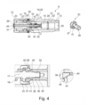
- the adapter non-return valve 10 has a spring 16 and is thus spring-loaded toward a closed position in direction of the second end 13, which results in the gas connection 14 is then closed when the adapter non-return valve 10 is closed.
- the adapter non-return valve 10 also comprises an actuator pin 17 which is displaceable in a first bore 45 in a sealing shaft 27, where the actuator pin has a first end 31 and a second end 32.
- the filler adapter 9 further comprises an outer part 19 being a universal holder 20 with handling means 21, and an inner part being a filling pipe 22, where the filling pipe 22 at said first end 12 of the filler adapter 9 comprises an inner thread 23.
- the filling pipe 22 has a second bore 25 provided with a first sealing 26.
- the sealing shaft is removable fixed in the filling pipe 22, where the sealing shaft 27 at the first end 12 of the filler adapter 9 is provided with a second sealing 28, and where a third sealing 29 is provided between the filling pipe 22 and the sealing shaft 27.
- the universal holder 20 and the filling pipe 22 are connected with a screw 30 being arranged in radially orientated bores in said universal holder 20 and said filling pipe 22, and that said screw 30 also is used for fixating of the shaft 27 in said filling pipe 22.
- the actuator pin 17 is fixedly connected by means of one-way connection means 36 to a hole 35 in the non-return valve piston 33 and the spring 16 is arranged between the moveable non-return piston valve 33 and a recess 34 in the fixed shaft 27.
- the non-return valve piston 33 has a first circular part 37 connected to a second circular part 38 with a smaller diameter than the first circular part 37, where a groove 39 with side edges 40 is positioned between the first circular part 37 and the second circular part 38, where a conical seal 41 is placed in the groove 39 and where the side edges 40 keeps the conical seal 41 in place.
- the non-return valve 10 in the filler adapter 9 is unique in the sense it can withstand the many different pressures, flow and temperatures it sees. It starts with the massive supersonic speed of gas passing over the conical seal 41 when blowing down the cylinder 2. In this process it gets very cold. Next step is the vacuum and then finally positive gas flowing in the other direction into the cylinder 2 until 200 or 300 bar is achieved. In all these cases it has to close fully and be absolutely leak tight both under vacuum or under high pressure. The small metal, side edges 40 that goes over the conical seal 41 protects it from going loose. A normal o-ring will just blow away here. In this arrangement it is protected from gas flow going under the conical seal 41 and thereby taking it out of its seat or groove 39.
- Fig. 5 shows the VIPR valve 11 with a VIPR non-return valve 18 and the filler adapter 9, where the filler adapter 9 comprises an inner thread 23 configured to be connected to an outer thread 24 on the VIPR valve 11.
- VIPR valve 11 arrives for filling placed on a cylinder 2 as shown in figure 1 .
- the cylinder 2 can be in different situations. Cylinder 2 filled with 200 or 300 bar. Cylinder 2 half empty between 300 to 0 bar, or complete empty. The filler adapter 9 is not mounted.
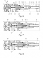
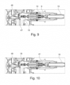
- Figs. 6-10 show the VIPR valve 11 with the medical gas filler adapter 9 and an activation shaft 15 in the different process steps.
- the figures show the most important segments of the system including pressure cylinder valve with integrated pressure regulator (VIPR) 11 having a VIPR non-return valve 18 and comprising an activation shaft 15 and a medical gas filler adapter 9, where the medical gas filler adapter 9 has an integrated adapter non-return valve 10 for use in filling and testing VIPR valve 11, where the filler adapter 9 comprises a first end 12 and a second end 13, where the first end 12 is configured to be connected to the VIPR valve 11 and the second end 13 is configured to be connected to the activation shaft 15 that is able to open the adapter non-return valve 10; where the adapter non-return valve 10 via a spring 16 is spring-loaded toward a closed position in direction of the second end 13, where the adapter non-return valve 10 comprises an actuator pin 17 configured to activate the VIPR non-return valve 18.
- VIPR pressure regulator
- the activation shaft 15 comprises a first end 42 with a protruding part 49 and a second end 43, where a gas connection 44 is arranged between said first end 42 and said second end 43.
- activation device 46 where the meaning of motor includes means for handling, rotating and what is otherwise necessary for handling, moving and operating the activation shaft 15.
- the filler adapter 9 is mounted on the thread 24 on the VIPR valve 11.
- the thread 24 can be of many different types, depending on which standard is used in which country.
- the filler adapter 9, which also has a thread 23, is screwed on and the O-ring 28 makes it a leak tight seal.
- the filler adapter 9 comprises an outside universal holder 20 with a number of internal parts like the filling pipe 22 with thread 23 which fits the individual gas cylinder 2.
- the figure further shows that the activation shaft 15 is connected with an activation device 46.
- Fig. 6 further shows the access to gas cylinder 47 and the main shut off valve 48.
- the activation shaft 15 is now moved forward and has a gastight seal 26.
- Activation shaft 15 moves forward and opens the adapter non-return valve 10, and that again leads to opening of the VIPR non-return valve 18. There is now open into the valve. The valve is still closed at the main shut off valve 48 down to the cylinder 2 by the access to gas cylinder 47. Any trapped gas inside the valve will now just come out.
- the main shut off valve 48 is opened. Therefore there is open to the cylinder 2 through the access to the gas cylinder 47. If 200 or 300 bar gas is in the cylinder, there will be a huge flow of gas through the filler adapter 9 to the outside.
- the conical seal 41 will be very exposed.
- the unique design of non-return valve piston 33 and conical seal 41 is preventing the conical seal 41 to get dislocated or damaged. The speed in the beginning is much higher than to the end, because the cylinder pressure drops during emptying. The temperature gets very low and ice can occur.
- Cylinder 2 will be completely emptied and this is done with a vacuum pump. That will remove any impurities or moisture that is prohibited for medical gases.
- the actual filling can now start. 200 or 300 bar gas now starts to flow into the cylinder 2.
- the cylinder 2 and valve get very warm, up to 65 deg. C is allowed.
- the amount of gas is measured either by pressure and temperature or by means of a mass flowmeter instrument.
- the gases that are filled are a mixture of O2 and N2O, pure O2, pure N2O, O2 and CO2 mixture.
- Main shut off valve 48 is now closed.
- the cylinder contains 200 or 300 bar.
- valve and filler adapter 9 are in this situation when leak is measured on the main shut off valve 48. A pressure increase or pressure drop are measured. Because the volume is known, calculating the leak rate in ccm/time is possible. The leak measured now is the leak over the main shut off valve 48. Here the requirement is different but in the range of 1-6 ccm/hour.
- Main shut off valve 48 is now closed.
- Activation shaft 15 moves forward to open non-return valve 10 in the filler adapter 9.
- the activation shaft 15 is not moved so much that it will open non-return valve 10, because leakage has to be measured on VIPR non-return valve 18.
- Leakage is possible too on VIPR non-return valve, because there is full cylinder pressure behind VIPR non-return valve, because there is open to the cylinder 2 over the main shut off valve 48.
- the leak requirement is typical between 1-6 ccm/hour.
- the filler adapter 9 can be used for many different VIPR valves 11.
- the VIPR non-return valve 18 in the VIPR 11 has a pin, and the length of the pin is very different in the market.
- the actuator pin 17 can be moved in different length by means of an activation device 46 and thereby open the VIPR non-return valve 18 in different length without damaging the non-return valve in the VIPR.
- the solutions today in the market has a fixed pin and can only be used for one type of VIPR valves 11.
Landscapes
- Engineering & Computer Science (AREA)
- Mechanical Engineering (AREA)
- General Engineering & Computer Science (AREA)
- Filling Or Discharging Of Gas Storage Vessels (AREA)
Claims (10)
- System, beinhaltend ein Druckzylinderventil mit integriertem Druckregulator (VIPR) (11), der ein VIPR-Rückschlagventil (18) aufweist und eine Aktivierungswelle (15) und einen Fülladapter für medizinische Gase (9) umfasst, um den Druckzylinder (2) zu leeren und zu füllen, wobei der Fülladapter für medizinische Gase (9) ein integriertes Adapterrückschlagventil (10) zur Verwendung beim Füllen und Prüfen des VIPR-Ventils (11) umfasst, und ein erstes Ende (12) und ein zweites Ende (13), wobei mindestens eine Gasverbindung (14) zwischen dem ersten Ende (12) und dem zweiten Ende (13) angeordnet ist, dadurch gekennzeichnet, dass das erste Ende (12) konfiguriert ist, um mit dem VIPR-Ventil (11) verbunden zu sein, und das zweite Ende (13) konfiguriert ist, um mit der Aktivierungswelle (15) verbunden zu sein, die in der Lage ist, das Adapterrückschlagventil (10) zu öffnen; wobei das Adapterrückschlagventil (10) über eine Feder (16) zu einer geschlossenen Position in Richtung des zweiten Endes (13) federbelastet ist, wodurch die mindestens eine Gasverbindung (14) geschlossen ist, wenn das Adapterrückschlagventil (10) geschlossen ist, dass das Adapterrückschlagventil (10) einen Betätigungsstift (17) umfasst, der konfiguriert ist, um das VIPR-Rückschlagventil (18) zu aktivieren, und wobei der Betätigungsstift (17) konfiguriert ist, um in unterschiedlicher Länge mittels der Aktivierungswelle (15) bewegt zu werden.
- System nach Anspruch 1, dadurch gekennzeichnet, dass die Aktivierungswelle (15) mit einer Aktivierungsvorrichtung (46) verbunden ist.
- System nach einem der Ansprüche 1 und 2, dadurch gekennzeichnet, dass der Fülladapter für medizinische Gase (9) einen Außenteil (19), der ein Universalhalter (20) mit Handhabungsmitteln (21) ist, und einen Innenteil umfasst, der ein Füllrohr (22) ist, wobei das Füllrohr (22) an dem ersten Ende (12) des Fülladapters für medizinische Gase (9) ein Innengewinde (23) umfasst, das konfiguriert ist, um mit einem Außengewinde (24) an dem VIPR-Ventil (11) verbunden zu sein.
- System nach Anspruch 3, dadurch gekennzeichnet, dass das Füllrohr (22) eine zweite Bohrung (25) umfasst, die konfiguriert ist, um die Aktivierungswelle (15) aufzunehmen, wobei die zweite Bohrung (25) mit einer ersten Dichtung (26) bereitgestellt ist, bevorzugt einem O-Ring, die konfiguriert ist, um gegen die Aktivierungswelle (15) abzudichten.
- System nach einem der Ansprüche 3 bis 4, dadurch gekennzeichnet, dass der Fülladapter (9) eine Welle (27) umfasst, die konfiguriert ist, um gegen das VIPR-Ventil (11) abzudichten, dass die Welle (27) entfernbar in dem Füllrohr (22) befestigt ist, dass die Welle (27) an dem ersten Ende (12) des Fülladapters (9) mit einer zweiten Dichtung (28) bereitgestellt ist, z. B. einem O-Ring, und dass eine dritte Dichtung (29), z. B. ein O-Ring, zwischen dem Füllrohr (22) und der Dichtungswelle (27) bereitgestellt ist.
- System nach Anspruch 5, dadurch gekennzeichnet, dass der Universalhalter (20) und das Füllrohr (22) mit einer Schraube (30) verbunden sind, die in radial ausgerichteten Bohrungen in dem Universalhalter (20) und dem Füllrohr (22) angeordnet ist, und dass die Schraube (30) auch zur Befestigung der Welle (27) in dem Füllrohr (22) verwendet wird.
- System nach einem der Ansprüche 5 bis 6, dadurch gekennzeichnet, dass eine erste Bohrung (45) für den Betätigungsstift (17) innerhalb der Welle (27) bereitgestellt ist, dass der Betätigungsstift (17) an einem ersten Ende (31) des Betätigungsstiftes (17) konfiguriert ist, um das VIPR-Rückschlagventil (18) in dem VIPR (11) zu aktivieren und an einem zweiten Ende (32) des Betätigungsstiftes (17) der Betätigungsstift (17) fest mit einem Rückschlagventilkolben (33) verbunden ist, dass die Feder (16) zwischen dem bewegbaren Rückschlagventilkolben (33) und einer Aussparung (34) in der festen Welle (27) angeordnet ist.
- System nach Anspruch 7, dadurch gekennzeichnet, dass der Betätigungsstift (17) fest mit einem Loch (35) in dem Rückschlagventilkolben (33) verbunden ist.
- System nach einem der Ansprüche 7 bis 8, dadurch gekennzeichnet, dass der Rückschlagventilkolben (33) einen ersten kreisförmigen Teil (37) umfasst, der mit einem zweiten kreisförmigen Teil (38) mit einem kleineren Durchmesser als der erste kreisförmige Teil (37) verbunden ist, wobei eine Nut (39) mit Seitenkanten (40) zwischen dem ersten kreisförmigen Teil (37) und dem zweiten kreisförmigen Teil (38) positioniert ist, wobei eine konische Dichtung (41) in der Nut (39) platziert ist und wobei die Seitenkanten (40) die konische Dichtung (41) an Ort und Stelle halten.
- System nach Anspruch 1 oder 2, dadurch gekennzeichnet, dass die Aktivierungswelle (15) konfiguriert ist, um mit dem zweiten Ende (13) des Fülladapters (9) verbunden zu sein; dass die Aktivierungswelle (15) ein erstes Ende (42) und ein zweites Ende (43) umfasst, mindestens eine Gasverbindung (44) zwischen dem ersten Ende (42) und dem zweiten Ende (43) bereitgestellt ist, wobei das erste Ende (42) einen vorstehenden Teil (49) beinhaltet, der konfiguriert ist, um das Adapterrückschlagventil (10) in Eingriff zu nehmen.
Applications Claiming Priority (1)
| Application Number | Priority Date | Filing Date | Title |
|---|---|---|---|
| DKPA201970117A DK180042B1 (en) | 2019-02-25 | 2019-02-25 | SYSTEM, MEDICAL GAS FILLING ADAPTERS AND ACTIVATIVE SHAFT FOR USE IN SUCH A SYSTEM |
Publications (3)
| Publication Number | Publication Date |
|---|---|
| EP3699480A1 EP3699480A1 (de) | 2020-08-26 |
| EP3699480C0 EP3699480C0 (de) | 2023-06-07 |
| EP3699480B1 true EP3699480B1 (de) | 2023-06-07 |
Family
ID=69374541
Family Applications (1)
| Application Number | Title | Priority Date | Filing Date |
|---|---|---|---|
| EP20159307.6A Active EP3699480B1 (de) | 2019-02-25 | 2020-02-25 | System, fülladapter für medizinische gase und aktivierungswelle zur verwendung in einem solchen system |
Country Status (2)
| Country | Link |
|---|---|
| EP (1) | EP3699480B1 (de) |
| DK (1) | DK180042B1 (de) |
Families Citing this family (2)
| Publication number | Priority date | Publication date | Assignee | Title |
|---|---|---|---|---|
| KR102496494B1 (ko) * | 2021-02-03 | 2023-02-07 | 티이엠씨 주식회사 | 유체배출포트와 연결되는 커넥터 및 커넥터가 연결된 유체압력조정밸브 |
| CN116025835B (zh) * | 2022-12-12 | 2025-05-09 | 内蒙古航天红岗机械有限公司 | 一种iv型装配式储氢气瓶内胆及装配方法 |
Family Cites Families (5)
| Publication number | Priority date | Publication date | Assignee | Title |
|---|---|---|---|---|
| US4210168A (en) * | 1977-10-17 | 1980-07-01 | Kabushiki Kaisha Neriki | Pressure-responsive valve unit for a fluid container |
| EP0983461B1 (de) * | 1997-05-22 | 2003-05-02 | Erwin Weh | Schnellanschlusskupplung |
| US20080035221A1 (en) * | 2004-07-21 | 2008-02-14 | African Oxygen Limited | Multifunctional Valve Unit |
| DE102007005864B4 (de) * | 2007-02-06 | 2008-10-30 | Sprügel, Friedrich A. | Verbindungsvorrichtung zum Verbinden eines Druckbehälters mit einem Flüssiggaseinfüllstutzen |
| WO2017067556A1 (en) | 2015-10-19 | 2017-04-27 | Dueholm Consulting Holding Aps | Automatic gas cylinder filling facility |
-
2019
- 2019-02-25 DK DKPA201970117A patent/DK180042B1/en not_active IP Right Cessation
-
2020
- 2020-02-25 EP EP20159307.6A patent/EP3699480B1/de active Active
Also Published As
| Publication number | Publication date |
|---|---|
| EP3699480C0 (de) | 2023-06-07 |
| DK180042B1 (en) | 2020-02-03 |
| DK201970117A1 (en) | 2020-02-03 |
| EP3699480A1 (de) | 2020-08-26 |
Similar Documents
| Publication | Publication Date | Title |
|---|---|---|
| US11467172B1 (en) | Dispensing assembly to facilitate dispensing of fluid from a sample cylinder and related methods | |
| AU2004219656B2 (en) | Protected integral cylinder valve, gas pressure regulator and flow meter, and method for refilling a gas cylinder so equipped | |
| EP1522786B1 (de) | Tank mit einer Ventilbüchse | |
| EP3699480A1 (de) | System, fülladapter für medizinische gase und aktivierungswelle zur verwendung in einem solchen system | |
| US20090166359A1 (en) | Element for Controlling Filling and/or Drawing of a Pressurized Gas, Tank and Circuit Provided with such an Element | |
| JPH10507249A (ja) | 圧力ガスボンベ用連結システム | |
| JPS62102133A (ja) | 揮発性液体のサンプリング装置 | |
| US11598488B2 (en) | Leak-proof fluid dispensing system with pressure sensor and adjustable dispensing regulator, dispensing control valve structure with pressure sensor, and dispensing control valve structure | |
| CA2383482C (en) | Pressure testing apparatus for gas service delivery system | |
| US20100228399A1 (en) | Pressure regulator assembly and system for the controlled storage and dispensing of a fluid | |
| US3759291A (en) | Valve fitting for bottles | |
| US11698327B2 (en) | Fluid sampling system | |
| CN103016793B (zh) | 用于气动阀连续运行的电磁阀旁路系统 | |
| WO2012015385A1 (en) | Adaptor assembly and system for pressurized containers | |
| EP3403019B1 (de) | Automatische gaszylinderfüllanlage | |
| CN115523420B (zh) | 二氧化碳充装装置及二氧化碳充装方法 | |
| US5810057A (en) | Pressure vessel fill protective device | |
| US20040099068A1 (en) | Sampling cylinder apparatus | |
| CA1051508A (en) | Port closure apparatus for differentially pressured vessels | |
| US5098847A (en) | Method and apparatus for portable testing of products from processing column | |
| CN218409526U (zh) | 二氧化碳充装装置 | |
| EP1750051A2 (de) | Gasflasche mit manuellen ON/OFF und ventil | |
| Brookman et al. | Gases and gas equipment | |
| Ilie et al. | NEW METODS OF TECHNICAL INSPECTION OF THE GAS BOTTLES | |
| US20220333742A1 (en) | Leak-proof fluid dispensing system with pressure sensor and pre-set internal dispensing pressure reduction regulator and dispensing control valve structure |
Legal Events
| Date | Code | Title | Description |
|---|---|---|---|
| PUAI | Public reference made under article 153(3) epc to a published international application that has entered the european phase |
Free format text: ORIGINAL CODE: 0009012 |
|
| STAA | Information on the status of an ep patent application or granted ep patent |
Free format text: STATUS: THE APPLICATION HAS BEEN PUBLISHED |
|
| AK | Designated contracting states |
Kind code of ref document: A1 Designated state(s): AL AT BE BG CH CY CZ DE DK EE ES FI FR GB GR HR HU IE IS IT LI LT LU LV MC MK MT NL NO PL PT RO RS SE SI SK SM TR |
|
| AX | Request for extension of the european patent |
Extension state: BA ME |
|
| STAA | Information on the status of an ep patent application or granted ep patent |
Free format text: STATUS: REQUEST FOR EXAMINATION WAS MADE |
|
| 17P | Request for examination filed |
Effective date: 20210223 |
|
| RBV | Designated contracting states (corrected) |
Designated state(s): AL AT BE BG CH CY CZ DE DK EE ES FI FR GB GR HR HU IE IS IT LI LT LU LV MC MK MT NL NO PL PT RO RS SE SI SK SM TR |
|
| GRAP | Despatch of communication of intention to grant a patent |
Free format text: ORIGINAL CODE: EPIDOSNIGR1 |
|
| STAA | Information on the status of an ep patent application or granted ep patent |
Free format text: STATUS: GRANT OF PATENT IS INTENDED |
|
| RIC1 | Information provided on ipc code assigned before grant |
Ipc: F17C 13/04 20060101AFI20220905BHEP |
|
| INTG | Intention to grant announced |
Effective date: 20220928 |
|
| GRAS | Grant fee paid |
Free format text: ORIGINAL CODE: EPIDOSNIGR3 |
|
| GRAA | (expected) grant |
Free format text: ORIGINAL CODE: 0009210 |
|
| STAA | Information on the status of an ep patent application or granted ep patent |
Free format text: STATUS: THE PATENT HAS BEEN GRANTED |
|
| AK | Designated contracting states |
Kind code of ref document: B1 Designated state(s): AL AT BE BG CH CY CZ DE DK EE ES FI FR GB GR HR HU IE IS IT LI LT LU LV MC MK MT NL NO PL PT RO RS SE SI SK SM TR |
|
| REG | Reference to a national code |
Ref country code: GB Ref legal event code: FG4D |
|
| REG | Reference to a national code |
Ref country code: CH Ref legal event code: EP Ref country code: AT Ref legal event code: REF Ref document number: 1576074 Country of ref document: AT Kind code of ref document: T Effective date: 20230615 |
|
| REG | Reference to a national code |
Ref country code: DE Ref legal event code: R096 Ref document number: 602020011462 Country of ref document: DE |
|
| U01 | Request for unitary effect filed |
Effective date: 20230622 |
|
| U07 | Unitary effect registered |
Designated state(s): AT BE BG DE DK EE FI FR IT LT LU LV MT NL PT SE SI Effective date: 20230629 |
|
| REG | Reference to a national code |
Ref country code: LT Ref legal event code: MG9D |
|
| PG25 | Lapsed in a contracting state [announced via postgrant information from national office to epo] |
Ref country code: NO Free format text: LAPSE BECAUSE OF FAILURE TO SUBMIT A TRANSLATION OF THE DESCRIPTION OR TO PAY THE FEE WITHIN THE PRESCRIBED TIME-LIMIT Effective date: 20230907 Ref country code: ES Free format text: LAPSE BECAUSE OF FAILURE TO SUBMIT A TRANSLATION OF THE DESCRIPTION OR TO PAY THE FEE WITHIN THE PRESCRIBED TIME-LIMIT Effective date: 20230607 |
|
| PG25 | Lapsed in a contracting state [announced via postgrant information from national office to epo] |
Ref country code: RS Free format text: LAPSE BECAUSE OF FAILURE TO SUBMIT A TRANSLATION OF THE DESCRIPTION OR TO PAY THE FEE WITHIN THE PRESCRIBED TIME-LIMIT Effective date: 20230607 Ref country code: HR Free format text: LAPSE BECAUSE OF FAILURE TO SUBMIT A TRANSLATION OF THE DESCRIPTION OR TO PAY THE FEE WITHIN THE PRESCRIBED TIME-LIMIT Effective date: 20230607 Ref country code: GR Free format text: LAPSE BECAUSE OF FAILURE TO SUBMIT A TRANSLATION OF THE DESCRIPTION OR TO PAY THE FEE WITHIN THE PRESCRIBED TIME-LIMIT Effective date: 20230908 |
|
| PG25 | Lapsed in a contracting state [announced via postgrant information from national office to epo] |
Ref country code: SK Free format text: LAPSE BECAUSE OF FAILURE TO SUBMIT A TRANSLATION OF THE DESCRIPTION OR TO PAY THE FEE WITHIN THE PRESCRIBED TIME-LIMIT Effective date: 20230607 |
|
| PG25 | Lapsed in a contracting state [announced via postgrant information from national office to epo] |
Ref country code: IS Free format text: LAPSE BECAUSE OF FAILURE TO SUBMIT A TRANSLATION OF THE DESCRIPTION OR TO PAY THE FEE WITHIN THE PRESCRIBED TIME-LIMIT Effective date: 20231007 |
|
| PG25 | Lapsed in a contracting state [announced via postgrant information from national office to epo] |
Ref country code: SM Free format text: LAPSE BECAUSE OF FAILURE TO SUBMIT A TRANSLATION OF THE DESCRIPTION OR TO PAY THE FEE WITHIN THE PRESCRIBED TIME-LIMIT Effective date: 20230607 Ref country code: SK Free format text: LAPSE BECAUSE OF FAILURE TO SUBMIT A TRANSLATION OF THE DESCRIPTION OR TO PAY THE FEE WITHIN THE PRESCRIBED TIME-LIMIT Effective date: 20230607 Ref country code: RO Free format text: LAPSE BECAUSE OF FAILURE TO SUBMIT A TRANSLATION OF THE DESCRIPTION OR TO PAY THE FEE WITHIN THE PRESCRIBED TIME-LIMIT Effective date: 20230607 Ref country code: IS Free format text: LAPSE BECAUSE OF FAILURE TO SUBMIT A TRANSLATION OF THE DESCRIPTION OR TO PAY THE FEE WITHIN THE PRESCRIBED TIME-LIMIT Effective date: 20231007 Ref country code: CZ Free format text: LAPSE BECAUSE OF FAILURE TO SUBMIT A TRANSLATION OF THE DESCRIPTION OR TO PAY THE FEE WITHIN THE PRESCRIBED TIME-LIMIT Effective date: 20230607 |
|
| PG25 | Lapsed in a contracting state [announced via postgrant information from national office to epo] |
Ref country code: PL Free format text: LAPSE BECAUSE OF FAILURE TO SUBMIT A TRANSLATION OF THE DESCRIPTION OR TO PAY THE FEE WITHIN THE PRESCRIBED TIME-LIMIT Effective date: 20230607 |
|
| REG | Reference to a national code |
Ref country code: DE Ref legal event code: R097 Ref document number: 602020011462 Country of ref document: DE |
|
| U20 | Renewal fee for the european patent with unitary effect paid |
Year of fee payment: 5 Effective date: 20240227 |
|
| PLBE | No opposition filed within time limit |
Free format text: ORIGINAL CODE: 0009261 |
|
| STAA | Information on the status of an ep patent application or granted ep patent |
Free format text: STATUS: NO OPPOSITION FILED WITHIN TIME LIMIT |
|
| 26N | No opposition filed |
Effective date: 20240308 |
|
| PG25 | Lapsed in a contracting state [announced via postgrant information from national office to epo] |
Ref country code: MC Free format text: LAPSE BECAUSE OF FAILURE TO SUBMIT A TRANSLATION OF THE DESCRIPTION OR TO PAY THE FEE WITHIN THE PRESCRIBED TIME-LIMIT Effective date: 20230607 |
|
| REG | Reference to a national code |
Ref country code: CH Ref legal event code: PL |
|
| PG25 | Lapsed in a contracting state [announced via postgrant information from national office to epo] |
Ref country code: CH Free format text: LAPSE BECAUSE OF NON-PAYMENT OF DUE FEES Effective date: 20240229 |
|
| GBPC | Gb: european patent ceased through non-payment of renewal fee |
Effective date: 20240225 |
|
| PG25 | Lapsed in a contracting state [announced via postgrant information from national office to epo] |
Ref country code: CH Free format text: LAPSE BECAUSE OF NON-PAYMENT OF DUE FEES Effective date: 20240229 |
|
| PG25 | Lapsed in a contracting state [announced via postgrant information from national office to epo] |
Ref country code: GB Free format text: LAPSE BECAUSE OF NON-PAYMENT OF DUE FEES Effective date: 20240225 |
|
| PG25 | Lapsed in a contracting state [announced via postgrant information from national office to epo] |
Ref country code: IE Free format text: LAPSE BECAUSE OF NON-PAYMENT OF DUE FEES Effective date: 20240225 |
|
| PG25 | Lapsed in a contracting state [announced via postgrant information from national office to epo] |
Ref country code: IE Free format text: LAPSE BECAUSE OF NON-PAYMENT OF DUE FEES Effective date: 20240225 Ref country code: GB Free format text: LAPSE BECAUSE OF NON-PAYMENT OF DUE FEES Effective date: 20240225 |
|
| U20 | Renewal fee for the european patent with unitary effect paid |
Year of fee payment: 6 Effective date: 20250227 |
|
| PG25 | Lapsed in a contracting state [announced via postgrant information from national office to epo] |
Ref country code: CY Free format text: LAPSE BECAUSE OF FAILURE TO SUBMIT A TRANSLATION OF THE DESCRIPTION OR TO PAY THE FEE WITHIN THE PRESCRIBED TIME-LIMIT; INVALID AB INITIO Effective date: 20200225 |
|
| PG25 | Lapsed in a contracting state [announced via postgrant information from national office to epo] |
Ref country code: HU Free format text: LAPSE BECAUSE OF FAILURE TO SUBMIT A TRANSLATION OF THE DESCRIPTION OR TO PAY THE FEE WITHIN THE PRESCRIBED TIME-LIMIT; INVALID AB INITIO Effective date: 20200225 |
|
| PG25 | Lapsed in a contracting state [announced via postgrant information from national office to epo] |
Ref country code: TR Free format text: LAPSE BECAUSE OF FAILURE TO SUBMIT A TRANSLATION OF THE DESCRIPTION OR TO PAY THE FEE WITHIN THE PRESCRIBED TIME-LIMIT Effective date: 20230607 |
|
| U20 | Renewal fee for the european patent with unitary effect paid |
Year of fee payment: 7 Effective date: 20260227 |