EP3699487A1 - Module d'éclairage de phare de véhicule automobile à distance focale variable - Google Patents
Module d'éclairage de phare de véhicule automobile à distance focale variable Download PDFInfo
- Publication number
- EP3699487A1 EP3699487A1 EP20155528.1A EP20155528A EP3699487A1 EP 3699487 A1 EP3699487 A1 EP 3699487A1 EP 20155528 A EP20155528 A EP 20155528A EP 3699487 A1 EP3699487 A1 EP 3699487A1
- Authority
- EP
- European Patent Office
- Prior art keywords
- lens
- motor vehicle
- light module
- projection optics
- vehicle headlight
- Prior art date
- Legal status (The legal status is an assumption and is not a legal conclusion. Google has not performed a legal analysis and makes no representation as to the accuracy of the status listed.)
- Granted
Links
Images


Classifications
-
- F—MECHANICAL ENGINEERING; LIGHTING; HEATING; WEAPONS; BLASTING
- F21—LIGHTING
- F21S—NON-PORTABLE LIGHTING DEVICES; SYSTEMS THEREOF; VEHICLE LIGHTING DEVICES SPECIALLY ADAPTED FOR VEHICLE EXTERIORS
- F21S41/00—Illuminating devices specially adapted for vehicle exteriors, e.g. headlamps
- F21S41/10—Illuminating devices specially adapted for vehicle exteriors, e.g. headlamps characterised by the light source
- F21S41/14—Illuminating devices specially adapted for vehicle exteriors, e.g. headlamps characterised by the light source characterised by the type of light source
- F21S41/141—Light emitting diodes [LED]
- F21S41/147—Light emitting diodes [LED] the main emission direction of the LED being angled to the optical axis of the illuminating device
-
- F—MECHANICAL ENGINEERING; LIGHTING; HEATING; WEAPONS; BLASTING
- F21—LIGHTING
- F21S—NON-PORTABLE LIGHTING DEVICES; SYSTEMS THEREOF; VEHICLE LIGHTING DEVICES SPECIALLY ADAPTED FOR VEHICLE EXTERIORS
- F21S41/00—Illuminating devices specially adapted for vehicle exteriors, e.g. headlamps
- F21S41/10—Illuminating devices specially adapted for vehicle exteriors, e.g. headlamps characterised by the light source
- F21S41/19—Attachment of light sources or lamp holders
-
- F—MECHANICAL ENGINEERING; LIGHTING; HEATING; WEAPONS; BLASTING
- F21—LIGHTING
- F21S—NON-PORTABLE LIGHTING DEVICES; SYSTEMS THEREOF; VEHICLE LIGHTING DEVICES SPECIALLY ADAPTED FOR VEHICLE EXTERIORS
- F21S41/00—Illuminating devices specially adapted for vehicle exteriors, e.g. headlamps
- F21S41/20—Illuminating devices specially adapted for vehicle exteriors, e.g. headlamps characterised by refractors, transparent cover plates, light guides or filters
- F21S41/25—Projection lenses
-
- F—MECHANICAL ENGINEERING; LIGHTING; HEATING; WEAPONS; BLASTING
- F21—LIGHTING
- F21S—NON-PORTABLE LIGHTING DEVICES; SYSTEMS THEREOF; VEHICLE LIGHTING DEVICES SPECIALLY ADAPTED FOR VEHICLE EXTERIORS
- F21S41/00—Illuminating devices specially adapted for vehicle exteriors, e.g. headlamps
- F21S41/20—Illuminating devices specially adapted for vehicle exteriors, e.g. headlamps characterised by refractors, transparent cover plates, light guides or filters
- F21S41/285—Refractors, transparent cover plates, light guides or filters not provided in groups F21S41/24 - F21S41/2805
-
- F—MECHANICAL ENGINEERING; LIGHTING; HEATING; WEAPONS; BLASTING
- F21—LIGHTING
- F21S—NON-PORTABLE LIGHTING DEVICES; SYSTEMS THEREOF; VEHICLE LIGHTING DEVICES SPECIALLY ADAPTED FOR VEHICLE EXTERIORS
- F21S41/00—Illuminating devices specially adapted for vehicle exteriors, e.g. headlamps
- F21S41/30—Illuminating devices specially adapted for vehicle exteriors, e.g. headlamps characterised by reflectors
- F21S41/32—Optical layout thereof
- F21S41/36—Combinations of two or more separate reflectors
- F21S41/365—Combinations of two or more separate reflectors successively reflecting the light
-
- F—MECHANICAL ENGINEERING; LIGHTING; HEATING; WEAPONS; BLASTING
- F21—LIGHTING
- F21S—NON-PORTABLE LIGHTING DEVICES; SYSTEMS THEREOF; VEHICLE LIGHTING DEVICES SPECIALLY ADAPTED FOR VEHICLE EXTERIORS
- F21S41/00—Illuminating devices specially adapted for vehicle exteriors, e.g. headlamps
- F21S41/60—Illuminating devices specially adapted for vehicle exteriors, e.g. headlamps characterised by a variable light distribution
- F21S41/63—Illuminating devices specially adapted for vehicle exteriors, e.g. headlamps characterised by a variable light distribution by acting on refractors, filters or transparent cover plates
- F21S41/635—Illuminating devices specially adapted for vehicle exteriors, e.g. headlamps characterised by a variable light distribution by acting on refractors, filters or transparent cover plates by moving refractors, filters or transparent cover plates
-
- F—MECHANICAL ENGINEERING; LIGHTING; HEATING; WEAPONS; BLASTING
- F21—LIGHTING
- F21S—NON-PORTABLE LIGHTING DEVICES; SYSTEMS THEREOF; VEHICLE LIGHTING DEVICES SPECIALLY ADAPTED FOR VEHICLE EXTERIORS
- F21S41/00—Illuminating devices specially adapted for vehicle exteriors, e.g. headlamps
- F21S41/60—Illuminating devices specially adapted for vehicle exteriors, e.g. headlamps characterised by a variable light distribution
- F21S41/67—Illuminating devices specially adapted for vehicle exteriors, e.g. headlamps characterised by a variable light distribution by acting on reflectors
- F21S41/675—Illuminating devices specially adapted for vehicle exteriors, e.g. headlamps characterised by a variable light distribution by acting on reflectors by moving reflectors
Definitions
- the present invention relates to a motor vehicle headlight light module according to the preamble of claim 1.
- Such a light module is from DE 10 2017 203 573 A1 known and has means for generating an internal light distribution and projection optics.
- the projection optics have a first lens and a second lens and are designed to emit the inner light distribution as the outer light distribution of the headlight.
- the projection optics have a variable focal length and one for adjusting the focal length having set up actuator means, wherein the actuator means is set up to change a position of at least one of the two lenses to the other of the two lenses.
- a system from Alvarez consisting of two specially shaped optical lenses with which different refractive powers could be achieved is known.
- the two lenses are matched to one another in such a way that a displacement of the two lenses relative to one another transversely to the direction of the light passing through the lenses changes the refractive power of the lens system formed from the two lenses.
- Alvarez's original intention was to develop glasses with which different visual distances can be shown clearly in a simple manner. In this area, the Alvarez lenses have been continuously developed in recent years, as they represent a cost-effective alternative to expensive progressive lenses.
- a light module with a liquid-filled lens is known whose shape and thus refractive power can be varied, for example, by pressure.
- That from the DE 10 2017 203 573 A1 known light module is a high beam module with adjustable headlight range, which can be used outside the high beam mode for projecting information onto the lane in front of the motor vehicle.
- the emission direction of the light module is pivoted downwards and the focal length of the light module is reduced by shifting at least one lens of the light module so that the information is sharply mapped onto the roadway.
- the information is an image of an internal light distribution or directional distribution of light rays that are reflected by a DMD chip (DMD: Digital Mirror Device).
- DMD Digital Mirror Device
- Such a DMD chip has a very large number (order of magnitude: 1 million) of micromirrors, the mirror position of which can be controlled individually and can be switched between two positions for each mirror.
- the DMD chip which has a total mirror area on the order of less than 10 square centimeters, is illuminated by a light source.
- the incident light reflected on the respective mirror is reflected to the projection optics or to other locations.
- the light reflected to the projection optics is projected onto the roadway and depicts the pattern of the positions of the micromirrors.
- the rest of the light is reflected onto an absorber, for example.
- the actuator means are set up to change the position by moving the first lens against the second lens and / or the second lens against the first lens transversely to an optical axis of the projection optics and that the first and the second lens for this purpose are set up to react to the change in position with a change in the focal length of the projection optics.
- the displacement of a lens along its optical axis used in the prior art tends to increase the required installation depth.
- the present invention replaces a lens shift taking place along the optical axis by a shift taking place transversely to the optical axis, which has the advantage that an increase in the installation depth (compared to a light module operating without focal length adjustment) is not required in the invention.
- the one used in the invention transverse to the optical axis
- the displacement of the lenses can be more easily integrated into a dust-proof housing than the displacement along the optical axis known from the prior art.
- a preferred embodiment is characterized in that the projection optics are set up to change a distance of a sharp image of the internal light distribution from the motor vehicle headlight by moving it.
- the projection optics have a first end position of the displacement and a second end position of the displacement.
- the projection optics are set up to sharply image the inner light distribution in the first end position at a distance from the headlight that is between 10 m and 15 m.
- Another preferred embodiment is characterized in that the projection optics are set up to sharply image the inner light distribution in the second end position at a distance from the headlight which is between 3 m and 8 m.
- the motor vehicle headlight device is set up to adjust the position with an electric motor, the one Drives threaded drive, which has a drive side coupled to the electric motor and an output side coupled to one of the two lenses.
- the light module has a dust-tight housing and that the two lenses are arranged in the dust-tight housing.
- Another preferred embodiment is characterized in that the first lens and the second lens are separated from one another by an air gap.
- the first lens has a first outer surface facing the inner light distribution to be imaged and a first inner surface facing the air gap.
- the first outer surface is a flat surface.
- Another preferred embodiment is characterized in that the first outer surface is curved in a concave and / or convex manner.
- the second lens has a second inner surface facing the air gap and a second outer surface facing the projection lens.
- the second outer surface is a is flat surface.
- the second outer surface is curved in a concave and / or convex manner.
- the Figure 1 a motor vehicle headlight 10 which is set up to illuminate an area 12 located in front of the motor vehicle headlight 10 through a transparent cover plate 14 of the motor vehicle headlight 10 with an external light distribution.
- the external light distribution results, for example, as a bright area on a roadway or a screen from the motor vehicle headlight 10.
- the motor vehicle headlight 10 has a light module 16.
- the light module 16 has means 18 for generating an internal light distribution localized within the light module 16.
- the light module 16 has projection optics 20 which are set up to sharply image the inner light distribution as the outer light distribution at an imaging distance 22 (focal distance) of several meters from the light module 16 in the area 12 located in front of the motor vehicle headlight 10.
- the projection optics 20 have a projection lens 48, a first lens 42.1, a second lens 42.2 and actuator means 24.
- the projection optics 20 is set up to display the inner light distribution as the outer light distribution of the Headlight 10 radiate.
- the projection optics 20 have a variable focal length.
- the actuating drive means 24 is set up to change a position of at least one of the two lenses 42.1, 42.2 in relation to the respective other of the two lenses 42.2, 42.1.
- the actuating drive means 24 is set up to change the position by shifting the first lens 42.1 against the second lens 42.2 and / or the second lens 42.2 against the first lens 42.1 transversely to an optical axis 44 of the projection optics 20.
- the actuator means 24 is, for example, an electric motor 24.1, for example a stepping motor, which is fastened with a first end to a housing 16.1 of the light module 16 and which is connected with the first lens 42.1 and / or the second lens 42.2 via a threaded drive 24.2 is.
- the stepper motor rotates, for example, a nut on a threaded rod which is connected to that of the first lens 42.1 or to the second lens 42.2, so that a rotation of the nut moves the coupled lens transversely to an optical axis of the lens. Simultaneous displacement of the two lenses against one another would also be conceivable.
- the first lens 42.1 and the second lens 42.2 are set up to react to the change in position by changing the focal length of the projection optics 20.
- the refractive power of the projection optics 20 is 20 dioptres, for example.
- the refractive power of the projection optics 20 can be varied by approximately a quarter according to the above-mentioned publication by Barbero.
- the change in the refractive power of the projection optics 20 must be approximately equal to 0.15, so that the above example value of 20 results in a changed value of 20.15.
- the value of 0.15 dioptres is certainly in the range of a quarter of the refractive power of 20 dioptres, so that a desired adjustment range 26 of the distance at which a sharp image of the inner light distribution is created can be achieved.
- the projection optics 48 have a first end position and a second end position for the displacement of the two lenses 42.1, 42.2 that takes place relative to one another.
- the projection optics 20 sharply image the inner light distribution at a distance from the headlight 10 that is between 10 m and 15 m. This is the end position which is also set during normal operation of the light module 16, in which the light module 16 is operated, for example, as a high beam module.
- the projection optics 20 sharply image the inner light distribution at a distance from the headlight 10 that is between 3 m and 8 m.
- This end position is set, for example, at walking speed, as it occurs, for example, in parking situations or in stop and go operation.
- the internal light distribution or directional distribution of reflected rays is produced, for example, by illuminating the micromirrors of a DMD chip 28 with a light source 50.
- the light source 50, the actuator means 24 and the position of the micromirrors of the DMD chip 28 are controlled by a control unit 43.
- a direction z coincides with the optical axis 44 and points from the DMD chip 28 to the projection optics 48.
- the z direction together with an x direction and a y direction, forms a right-handed coordinate system.
- Figure 2 shows a preferred embodiment of a light module 16 as a dust-tight light module 16.
- the first lens 42.1 and the second lens 42.2 are separated from one another by an air gap 45.
- the first lens 42.1 has a first outer surface 42.1.1 facing the inner light distribution to be imaged (here: arrangement of the micromirrors of the DMD chip 28) and a the first inner surface 42.1.2 facing the air gap 45.
- the first outer surface 42.1.1 is, for example, a flat surface.
- the second lens 42.2 has a second inner surface 42.2.1 facing the air gap 45 and a second outer surface 42.2.2 facing the projection lens 48.
- the second outer surface 42.2.2 is, for example, a flat surface.
- the outer surfaces 42.1.1 and 42.2.2 can also be concave or convex surfaces.
- the following statements relating to the thickness of the first lens 42.1 each relate to a distance of a first imaginary flat surface, which is perpendicular to the optical axis 44 in the first lens 42.1, from the first inner surface 42.1.2.
- the following statements relating to the thickness of the second lens 42.2 in this case each relate to a distance between a second imaginary flat surface, which is perpendicular to the optical axis 44 in the second lens 42.2, from the second inner surface 42.2.1.
- the optical axis 44 is in FIG Figure 1 depicted and falls in the Figure 2 with the light beam 56 together.
- First and second lenses which satisfy these formulas represent examples of a first lens 42.1 and a second lens 42.2 which are set up to react to the change in the position by changing the focal length of the projection optics.
- the light module 16 has the light source 50, primary optics 52 and a DMD chip 28 as means 18 for generating the internal light distribution localized within the light module 16.
- the light source 50 is a semiconductor light source which is mounted on a first printed circuit board 54 is arranged and the light 56 emits in the direction of the primary optics 52.
- the primary optics 52 have a light-refracting part 52.1 and a reflector 52.2.
- the refractive part 52.1 is illuminated by the light source 50 and directs the light 56 onto the reflector 52.2.
- the reflector 52.2 directs the light 56 incident on it from the refractive part 52.1 onto a reflecting surface of a front side 28.1 of the DMD chip 28, the reflecting surface consisting of a multiplicity of micromirrors. It is essential that the primary optics 52 direct the light 56 from the light source 50 onto the DMD chip 28. How and with which optical elements this is done in detail is not essential to the invention.
- a swivel position of the micromirrors can be switched between a first swivel position and a second swivel position individually for each micromirror or at least for a subset of the micromirrors.
- Each micromirror that is in the first pivoting position deflects the light incident on it from the primary optics 52 onto the projection optics 20.
- Each micromirror that is in the second pivot position deflects the light 56 incident on it from the primary optics 52 in such a way that the deflected light does not fall on the projection optics 20. This light is directed, for example, onto an absorber 58 and absorbed there, so that it cannot generate any disruptive light effects.
- the projection optics 20 aim this at them from the DMD chip 28 incident light 56 in the area 12 located in front of the motor vehicle headlight 10 (cf. Figure 1 ). When the light module 16 is used as intended, the lane in front of the motor vehicle is illuminated with this light.
- the projection optics 20 have a projection lens 48 made of transparent plastic or glass.
- the projection optics 20 can also have several lenses, for example an arrangement of an achromatic lens and an imaging lens.
- the path of the light 56 from the light source 50 up to its exit from the projection optics 20 through the projection optics 20 lies completely in the dust-tight sealed interior 60.
- This interior 60 is made up of a front housing part 62 and a central support element 64 , the DMD chip 28, a first printed circuit board 54, the projection optics 20 and a dust-tight pressure compensation membrane 68.
- the first circuit board 54 is used to contact the light source.
- a second circuit board 55 is used to contact the DMD chip 28.
- the second circuit board lies completely outside the dust-tight interior 60.
- the front housing part 62 be made of plastic and that seals and sealing lips 66 formed on flange areas of the front housing part 62 are made of sealing material .
- the central support element 64 has an interior space 60 facing front side 64.1 and a rear side 64.2.
- the central carrier element 64 has a first partial area 64.3 on the light source and primary optics side and a second partial area 64.4 on the DMD chip side. These two subregions 64.3 and 64.4 are spatially separated from one another, but are cohesively connected and together form the one-piece central support element 64.
- the two subregions 64.3 and 64.4 enclose an angle that is greater than 90 ° but less than 180 °.
- the central support element 64 is preferably made of metal and also serves as a heat sink, which absorbs the heat released in the light source 50 and emits it to the surroundings of the light module 16.
- the first printed circuit board 54 is firmly connected to the front side 64.1 of the central carrier element 64 in its first partial area 64.3.
- the connection is, for example, a screw and / or adhesive connection.
- a front side of the first printed circuit board 54 carries the light source 50 implemented as a semiconductor light source and the primary optics 52.
- a rear side of the first printed circuit board 54 faces the front side 64.1 of the central carrier element 64.
- the laterally protruding edge of the front side 64.1 of the central carrier element 64 forms part of an interior-side flange region 64.5 of the central carrier element 64.
- the second sub-area 64.4 of the central carrier element 30 has a carrier element window 72.
- Carrier element window 72 circumferential window edge area forms a window flange area 36 on rear side 64.2 of central carrier element 64.
- DMD chip 28 is arranged on rear side 64.2 of central carrier element 64 in its second partial area 64.4 so that it covers carrier element window 72.
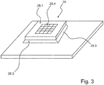
- the DMD chip 28 has two broad sides in the form of a front side 28.1 and a rear side, the front side and rear sides being separated from one another by narrow side sides 28.3 lying between them.
- the front side 28.1 of the DMD chip 28 has a central chip area in which the micromirrors 28.4 are arranged, and it has a flange area 28.5 which encircles the central chip area in a closed curve and in which no micromirrors 28.4 are arranged.
- the number of micromirrors is, for example, about 1.3 million, which are arranged in a matrix with 1152 columns and 1152 rows.
- Such DMD chips digital mirror device
- Such DMD chips are manufactured and sold, for example, by the company Texas Instruments.
- the Figures 2 and 3 show in combination with one another that the DMD chip 28 is arranged overall in such a way that the two flange regions 74 and 28.5 are opposite one another. Between the two flange areas 74 and 28.5 there is a DMD chip seal 76 in the form of a flat seal which is held by the flange areas 78 and 28.5 with a pressing force pressing these flange areas against one another and which runs around the carrier element window 72 in a closed curve.
- the projection optics 20 optionally have a further lens which, together with the projection lens 48, forms an anamorphic projection optics 20.
Landscapes
- Engineering & Computer Science (AREA)
- General Engineering & Computer Science (AREA)
- Physics & Mathematics (AREA)
- Microelectronics & Electronic Packaging (AREA)
- Optics & Photonics (AREA)
- Non-Portable Lighting Devices Or Systems Thereof (AREA)
Applications Claiming Priority (1)
| Application Number | Priority Date | Filing Date | Title |
|---|---|---|---|
| DE102019103033.1A DE102019103033A1 (de) | 2019-02-07 | 2019-02-07 | Kraftfahrzeugscheinwerferlichtmodul mit einer veränderlichen Fokusweite |
Publications (2)
| Publication Number | Publication Date |
|---|---|
| EP3699487A1 true EP3699487A1 (fr) | 2020-08-26 |
| EP3699487B1 EP3699487B1 (fr) | 2022-08-24 |
Family
ID=69500540
Family Applications (1)
| Application Number | Title | Priority Date | Filing Date |
|---|---|---|---|
| EP20155528.1A Active EP3699487B1 (fr) | 2019-02-07 | 2020-02-05 | Module d'éclairage de phare de véhicule automobile à distance focale variable |
Country Status (2)
| Country | Link |
|---|---|
| EP (1) | EP3699487B1 (fr) |
| DE (1) | DE102019103033A1 (fr) |
Families Citing this family (1)
| Publication number | Priority date | Publication date | Assignee | Title |
|---|---|---|---|---|
| DE102021207081A1 (de) | 2021-07-06 | 2023-01-12 | Robert Bosch Gesellschaft mit beschränkter Haftung | Projektionsmodul |
Citations (13)
| Publication number | Priority date | Publication date | Assignee | Title |
|---|---|---|---|---|
| FR352391A (fr) * | 1905-03-04 | 1905-08-09 | Amedee Couesnon | Perfectionnements apportés aux phares pour voitures automobiles |
| DE1290357B (de) | 1964-12-03 | 1969-03-06 | Optical Res & Dev Corp | Optische Vorrichtung mit der Wirkung einer Linse mit veraenderbarer Brennweite |
| JPH02119001A (ja) * | 1988-10-28 | 1990-05-07 | Koito Mfg Co Ltd | 車両用前照灯 |
| EP1234716A2 (fr) * | 2001-02-21 | 2002-08-28 | Zizala Lichtsysteme GmbH | Phare de véhicule |
| DE69613748T2 (de) * | 1995-04-19 | 2002-09-05 | Automotive Lighting Italia S.P.A., Venaria Reale | Adaptives Beleuchtungsgerät, insbesondere Fahrzeugscheinwerfer |
| DE10203573A1 (de) | 2002-01-30 | 2003-08-21 | Kirchner Fraenk Rohr | Anschlusseinrichtung zum wasserdichten Anschließen eines Wellrohres |
| DE202007018181U1 (de) * | 2007-12-31 | 2008-05-08 | Automotive Lighting Reutlingen Gmbh | Projektionsmodul mit dynamischer Kurvenlichtfunktion |
| DE102011087306A1 (de) * | 2011-11-29 | 2013-05-29 | Osram Gmbh | Fahrzeugbeleuchtungsvorrichtung |
| DE102014213636A1 (de) * | 2013-07-16 | 2015-01-22 | Koito Manufacturing Co., Ltd. | Fahrzeugleuchte |
| WO2015058227A1 (fr) * | 2013-10-25 | 2015-04-30 | Zizala Lichtsysteme Gmbh | Module d'éclairage à micro-projection destiné à un projecteur de véhicule automobile |
| DE102016108675A1 (de) * | 2015-05-19 | 2016-11-24 | Panasonic Intellectual Property Management Co., Ltd. | Leuchteinrichtung und selbige beinhaltendes Kraftfahrzeug |
| EP3301497A1 (fr) | 2016-09-28 | 2018-04-04 | Valeo Vision | Module d'eclairage automobile avec lentille a focale reglable |
| DE102017203573A1 (de) | 2016-10-10 | 2018-04-12 | Hyundai Motor Company | Beleuchtungsvorrichtung für ein fahrzeug |
Family Cites Families (4)
| Publication number | Priority date | Publication date | Assignee | Title |
|---|---|---|---|---|
| WO2010024668A1 (fr) * | 2008-08-25 | 2010-03-04 | Akkolens International B.V. | Système d’éclairage avant adaptatif |
| DE102011100279A1 (de) * | 2011-04-29 | 2012-10-31 | Digital Imaging Systems Gmbh | Dynamisches Beleuchtungssystem |
| WO2018099826A1 (fr) * | 2016-11-29 | 2018-06-07 | Philips Lighting Holding B.V. | Dispositifs, systèmes et procédés permettant de faire varier des structures de faisceau |
| DE202017103122U1 (de) * | 2017-02-27 | 2018-05-29 | Bartenbach Holding Gmbh | Zoom-Strahler |
-
2019
- 2019-02-07 DE DE102019103033.1A patent/DE102019103033A1/de not_active Withdrawn
-
2020
- 2020-02-05 EP EP20155528.1A patent/EP3699487B1/fr active Active
Patent Citations (13)
| Publication number | Priority date | Publication date | Assignee | Title |
|---|---|---|---|---|
| FR352391A (fr) * | 1905-03-04 | 1905-08-09 | Amedee Couesnon | Perfectionnements apportés aux phares pour voitures automobiles |
| DE1290357B (de) | 1964-12-03 | 1969-03-06 | Optical Res & Dev Corp | Optische Vorrichtung mit der Wirkung einer Linse mit veraenderbarer Brennweite |
| JPH02119001A (ja) * | 1988-10-28 | 1990-05-07 | Koito Mfg Co Ltd | 車両用前照灯 |
| DE69613748T2 (de) * | 1995-04-19 | 2002-09-05 | Automotive Lighting Italia S.P.A., Venaria Reale | Adaptives Beleuchtungsgerät, insbesondere Fahrzeugscheinwerfer |
| EP1234716A2 (fr) * | 2001-02-21 | 2002-08-28 | Zizala Lichtsysteme GmbH | Phare de véhicule |
| DE10203573A1 (de) | 2002-01-30 | 2003-08-21 | Kirchner Fraenk Rohr | Anschlusseinrichtung zum wasserdichten Anschließen eines Wellrohres |
| DE202007018181U1 (de) * | 2007-12-31 | 2008-05-08 | Automotive Lighting Reutlingen Gmbh | Projektionsmodul mit dynamischer Kurvenlichtfunktion |
| DE102011087306A1 (de) * | 2011-11-29 | 2013-05-29 | Osram Gmbh | Fahrzeugbeleuchtungsvorrichtung |
| DE102014213636A1 (de) * | 2013-07-16 | 2015-01-22 | Koito Manufacturing Co., Ltd. | Fahrzeugleuchte |
| WO2015058227A1 (fr) * | 2013-10-25 | 2015-04-30 | Zizala Lichtsysteme Gmbh | Module d'éclairage à micro-projection destiné à un projecteur de véhicule automobile |
| DE102016108675A1 (de) * | 2015-05-19 | 2016-11-24 | Panasonic Intellectual Property Management Co., Ltd. | Leuchteinrichtung und selbige beinhaltendes Kraftfahrzeug |
| EP3301497A1 (fr) | 2016-09-28 | 2018-04-04 | Valeo Vision | Module d'eclairage automobile avec lentille a focale reglable |
| DE102017203573A1 (de) | 2016-10-10 | 2018-04-12 | Hyundai Motor Company | Beleuchtungsvorrichtung für ein fahrzeug |
Also Published As
| Publication number | Publication date |
|---|---|
| DE102019103033A1 (de) | 2020-08-13 |
| EP3699487B1 (fr) | 2022-08-24 |
Similar Documents
| Publication | Publication Date | Title |
|---|---|---|
| EP2910847B1 (fr) | Module d'éclairage d'un projecteur de véhicule automobile et projecteur avec un tel module d'éclairage | |
| EP2789900B1 (fr) | Module d'éclairage pour un dispositif d'éclairage de véhicule automobile | |
| AT519462B1 (de) | Fahrzeugscheinwerfer | |
| EP2799762B1 (fr) | Module d'éclairage de phare de véhicule automobile | |
| EP0221416B1 (fr) | Projecteur de croisement ou de brouillard pour automobiles | |
| EP3510320B1 (fr) | Projecteur de véhicule | |
| DE102012202290B4 (de) | Lichtmodul für ein blendungsfreies Kraftfahrzeug-Fernlicht | |
| DE102009020593B4 (de) | Zur Erzeugung einer definierten Overhead-Beleuchtung eingerichteter Fahrzeugscheinwerfer | |
| DE102005019811A1 (de) | Lichtaussendende Vorrichtung | |
| EP2918898A1 (fr) | Dispositif d'éclairage pour un véhicule | |
| EP3301350B1 (fr) | Module d'éclairage pour phare de véhicule automobile | |
| EP3546822B1 (fr) | Module lumineux comportant un micromiroir pour un phare de véhicule automobile | |
| AT518266A4 (de) | Halterungsvorrichtung für ein elektronisches Bauteil | |
| EP3203140A1 (fr) | Dispositif d'éclairage pour un véhicule et procédé de fonctionnement correspondant | |
| DE112017001785T5 (de) | Head-up-Anzeigegerät | |
| DE102015219211B4 (de) | Lichtmodul für eine Kfz-Beleuchtungseinrichtung | |
| EP3699487B1 (fr) | Module d'éclairage de phare de véhicule automobile à distance focale variable | |
| DE202021103134U1 (de) | Integrierte Kamera-Umfeldleuchtenvorrichtung und diese aufweisender Seitenspiegel | |
| DE102019123515B4 (de) | Kraftfahrzeugscheinwerfer mit zwei Projektionslichtmodulen unterschiedlicher Brennweite und gleich breit ausgeleuchteten Lichtaustrittslinsen | |
| EP1418454B1 (fr) | Microscope et méthode de changement du flux lumineux dans un microscope | |
| DE102020200645A1 (de) | Blende, optisches system und lithographieanlage | |
| DE102018217651A1 (de) | Lichtmodul für eine Beleuchtungsvorrichtung eines Kraftfahrzeugs | |
| DE202021103135U1 (de) | Integrierte Kamera-Umfeldleuchtenvorrichtung und diese aufweisender Seitenspiegel | |
| DE102019108478A1 (de) | Kraftfahrzeugscheinwerfer mit einstellbarem Abstand einer scharf abgebildeten Lichtverteilung | |
| DE10341805A1 (de) | Beleuchtungsvorrichtung |
Legal Events
| Date | Code | Title | Description |
|---|---|---|---|
| PUAI | Public reference made under article 153(3) epc to a published international application that has entered the european phase |
Free format text: ORIGINAL CODE: 0009012 |
|
| STAA | Information on the status of an ep patent application or granted ep patent |
Free format text: STATUS: THE APPLICATION HAS BEEN PUBLISHED |
|
| AK | Designated contracting states |
Kind code of ref document: A1 Designated state(s): AL AT BE BG CH CY CZ DE DK EE ES FI FR GB GR HR HU IE IS IT LI LT LU LV MC MK MT NL NO PL PT RO RS SE SI SK SM TR |
|
| AX | Request for extension of the european patent |
Extension state: BA ME |
|
| STAA | Information on the status of an ep patent application or granted ep patent |
Free format text: STATUS: REQUEST FOR EXAMINATION WAS MADE |
|
| 17P | Request for examination filed |
Effective date: 20210226 |
|
| RBV | Designated contracting states (corrected) |
Designated state(s): AL AT BE BG CH CY CZ DE DK EE ES FI FR GB GR HR HU IE IS IT LI LT LU LV MC MK MT NL NO PL PT RO RS SE SI SK SM TR |
|
| GRAP | Despatch of communication of intention to grant a patent |
Free format text: ORIGINAL CODE: EPIDOSNIGR1 |
|
| STAA | Information on the status of an ep patent application or granted ep patent |
Free format text: STATUS: GRANT OF PATENT IS INTENDED |
|
| INTG | Intention to grant announced |
Effective date: 20220325 |
|
| GRAS | Grant fee paid |
Free format text: ORIGINAL CODE: EPIDOSNIGR3 |
|
| GRAA | (expected) grant |
Free format text: ORIGINAL CODE: 0009210 |
|
| STAA | Information on the status of an ep patent application or granted ep patent |
Free format text: STATUS: THE PATENT HAS BEEN GRANTED |
|
| AK | Designated contracting states |
Kind code of ref document: B1 Designated state(s): AL AT BE BG CH CY CZ DE DK EE ES FI FR GB GR HR HU IE IS IT LI LT LU LV MC MK MT NL NO PL PT RO RS SE SI SK SM TR |
|
| REG | Reference to a national code |
Ref country code: CH Ref legal event code: EP |
|
| REG | Reference to a national code |
Ref country code: DE Ref legal event code: R096 Ref document number: 502020001557 Country of ref document: DE |
|
| REG | Reference to a national code |
Ref country code: IE Ref legal event code: FG4D Free format text: LANGUAGE OF EP DOCUMENT: GERMAN |
|
| REG | Reference to a national code |
Ref country code: AT Ref legal event code: REF Ref document number: 1513887 Country of ref document: AT Kind code of ref document: T Effective date: 20220915 |
|
| REG | Reference to a national code |
Ref country code: LT Ref legal event code: MG9D |
|
| REG | Reference to a national code |
Ref country code: NL Ref legal event code: MP Effective date: 20220824 |
|
| PG25 | Lapsed in a contracting state [announced via postgrant information from national office to epo] |
Ref country code: SE Free format text: LAPSE BECAUSE OF FAILURE TO SUBMIT A TRANSLATION OF THE DESCRIPTION OR TO PAY THE FEE WITHIN THE PRESCRIBED TIME-LIMIT Effective date: 20220824 Ref country code: RS Free format text: LAPSE BECAUSE OF FAILURE TO SUBMIT A TRANSLATION OF THE DESCRIPTION OR TO PAY THE FEE WITHIN THE PRESCRIBED TIME-LIMIT Effective date: 20220824 Ref country code: PT Free format text: LAPSE BECAUSE OF FAILURE TO SUBMIT A TRANSLATION OF THE DESCRIPTION OR TO PAY THE FEE WITHIN THE PRESCRIBED TIME-LIMIT Effective date: 20221226 Ref country code: NO Free format text: LAPSE BECAUSE OF FAILURE TO SUBMIT A TRANSLATION OF THE DESCRIPTION OR TO PAY THE FEE WITHIN THE PRESCRIBED TIME-LIMIT Effective date: 20221124 Ref country code: NL Free format text: LAPSE BECAUSE OF FAILURE TO SUBMIT A TRANSLATION OF THE DESCRIPTION OR TO PAY THE FEE WITHIN THE PRESCRIBED TIME-LIMIT Effective date: 20220824 Ref country code: LV Free format text: LAPSE BECAUSE OF FAILURE TO SUBMIT A TRANSLATION OF THE DESCRIPTION OR TO PAY THE FEE WITHIN THE PRESCRIBED TIME-LIMIT Effective date: 20220824 Ref country code: LT Free format text: LAPSE BECAUSE OF FAILURE TO SUBMIT A TRANSLATION OF THE DESCRIPTION OR TO PAY THE FEE WITHIN THE PRESCRIBED TIME-LIMIT Effective date: 20220824 Ref country code: FI Free format text: LAPSE BECAUSE OF FAILURE TO SUBMIT A TRANSLATION OF THE DESCRIPTION OR TO PAY THE FEE WITHIN THE PRESCRIBED TIME-LIMIT Effective date: 20220824 |
|
| PG25 | Lapsed in a contracting state [announced via postgrant information from national office to epo] |
Ref country code: PL Free format text: LAPSE BECAUSE OF FAILURE TO SUBMIT A TRANSLATION OF THE DESCRIPTION OR TO PAY THE FEE WITHIN THE PRESCRIBED TIME-LIMIT Effective date: 20220824 Ref country code: IS Free format text: LAPSE BECAUSE OF FAILURE TO SUBMIT A TRANSLATION OF THE DESCRIPTION OR TO PAY THE FEE WITHIN THE PRESCRIBED TIME-LIMIT Effective date: 20221224 Ref country code: HR Free format text: LAPSE BECAUSE OF FAILURE TO SUBMIT A TRANSLATION OF THE DESCRIPTION OR TO PAY THE FEE WITHIN THE PRESCRIBED TIME-LIMIT Effective date: 20220824 Ref country code: GR Free format text: LAPSE BECAUSE OF FAILURE TO SUBMIT A TRANSLATION OF THE DESCRIPTION OR TO PAY THE FEE WITHIN THE PRESCRIBED TIME-LIMIT Effective date: 20221125 |
|
| PG25 | Lapsed in a contracting state [announced via postgrant information from national office to epo] |
Ref country code: SM Free format text: LAPSE BECAUSE OF FAILURE TO SUBMIT A TRANSLATION OF THE DESCRIPTION OR TO PAY THE FEE WITHIN THE PRESCRIBED TIME-LIMIT Effective date: 20220824 Ref country code: RO Free format text: LAPSE BECAUSE OF FAILURE TO SUBMIT A TRANSLATION OF THE DESCRIPTION OR TO PAY THE FEE WITHIN THE PRESCRIBED TIME-LIMIT Effective date: 20220824 Ref country code: ES Free format text: LAPSE BECAUSE OF FAILURE TO SUBMIT A TRANSLATION OF THE DESCRIPTION OR TO PAY THE FEE WITHIN THE PRESCRIBED TIME-LIMIT Effective date: 20220824 Ref country code: DK Free format text: LAPSE BECAUSE OF FAILURE TO SUBMIT A TRANSLATION OF THE DESCRIPTION OR TO PAY THE FEE WITHIN THE PRESCRIBED TIME-LIMIT Effective date: 20220824 Ref country code: CZ Free format text: LAPSE BECAUSE OF FAILURE TO SUBMIT A TRANSLATION OF THE DESCRIPTION OR TO PAY THE FEE WITHIN THE PRESCRIBED TIME-LIMIT Effective date: 20220824 |
|
| REG | Reference to a national code |
Ref country code: DE Ref legal event code: R097 Ref document number: 502020001557 Country of ref document: DE |
|
| PG25 | Lapsed in a contracting state [announced via postgrant information from national office to epo] |
Ref country code: SK Free format text: LAPSE BECAUSE OF FAILURE TO SUBMIT A TRANSLATION OF THE DESCRIPTION OR TO PAY THE FEE WITHIN THE PRESCRIBED TIME-LIMIT Effective date: 20220824 Ref country code: EE Free format text: LAPSE BECAUSE OF FAILURE TO SUBMIT A TRANSLATION OF THE DESCRIPTION OR TO PAY THE FEE WITHIN THE PRESCRIBED TIME-LIMIT Effective date: 20220824 |
|
| PG25 | Lapsed in a contracting state [announced via postgrant information from national office to epo] |
Ref country code: AL Free format text: LAPSE BECAUSE OF FAILURE TO SUBMIT A TRANSLATION OF THE DESCRIPTION OR TO PAY THE FEE WITHIN THE PRESCRIBED TIME-LIMIT Effective date: 20220824 |
|
| PLBE | No opposition filed within time limit |
Free format text: ORIGINAL CODE: 0009261 |
|
| STAA | Information on the status of an ep patent application or granted ep patent |
Free format text: STATUS: NO OPPOSITION FILED WITHIN TIME LIMIT |
|
| 26N | No opposition filed |
Effective date: 20230525 |
|
| PG25 | Lapsed in a contracting state [announced via postgrant information from national office to epo] |
Ref country code: SI Free format text: LAPSE BECAUSE OF FAILURE TO SUBMIT A TRANSLATION OF THE DESCRIPTION OR TO PAY THE FEE WITHIN THE PRESCRIBED TIME-LIMIT Effective date: 20220824 |
|
| PG25 | Lapsed in a contracting state [announced via postgrant information from national office to epo] |
Ref country code: MC Free format text: LAPSE BECAUSE OF FAILURE TO SUBMIT A TRANSLATION OF THE DESCRIPTION OR TO PAY THE FEE WITHIN THE PRESCRIBED TIME-LIMIT Effective date: 20220824 |
|
| REG | Reference to a national code |
Ref country code: CH Ref legal event code: PL |
|
| REG | Reference to a national code |
Ref country code: BE Ref legal event code: MM Effective date: 20230228 |
|
| PG25 | Lapsed in a contracting state [announced via postgrant information from national office to epo] |
Ref country code: LU Free format text: LAPSE BECAUSE OF NON-PAYMENT OF DUE FEES Effective date: 20230205 Ref country code: LI Free format text: LAPSE BECAUSE OF NON-PAYMENT OF DUE FEES Effective date: 20230228 Ref country code: CH Free format text: LAPSE BECAUSE OF NON-PAYMENT OF DUE FEES Effective date: 20230228 |
|
| REG | Reference to a national code |
Ref country code: IE Ref legal event code: MM4A |
|
| PG25 | Lapsed in a contracting state [announced via postgrant information from national office to epo] |
Ref country code: IE Free format text: LAPSE BECAUSE OF NON-PAYMENT OF DUE FEES Effective date: 20230205 Ref country code: FR Free format text: LAPSE BECAUSE OF NON-PAYMENT OF DUE FEES Effective date: 20230228 |
|
| PG25 | Lapsed in a contracting state [announced via postgrant information from national office to epo] |
Ref country code: BE Free format text: LAPSE BECAUSE OF NON-PAYMENT OF DUE FEES Effective date: 20230228 |
|
| PG25 | Lapsed in a contracting state [announced via postgrant information from national office to epo] |
Ref country code: IT Free format text: LAPSE BECAUSE OF FAILURE TO SUBMIT A TRANSLATION OF THE DESCRIPTION OR TO PAY THE FEE WITHIN THE PRESCRIBED TIME-LIMIT Effective date: 20220824 |
|
| GBPC | Gb: european patent ceased through non-payment of renewal fee |
Effective date: 20240205 |
|
| PG25 | Lapsed in a contracting state [announced via postgrant information from national office to epo] |
Ref country code: BG Free format text: LAPSE BECAUSE OF FAILURE TO SUBMIT A TRANSLATION OF THE DESCRIPTION OR TO PAY THE FEE WITHIN THE PRESCRIBED TIME-LIMIT Effective date: 20220824 |
|
| PG25 | Lapsed in a contracting state [announced via postgrant information from national office to epo] |
Ref country code: BG Free format text: LAPSE BECAUSE OF FAILURE TO SUBMIT A TRANSLATION OF THE DESCRIPTION OR TO PAY THE FEE WITHIN THE PRESCRIBED TIME-LIMIT Effective date: 20220824 |
|
| PG25 | Lapsed in a contracting state [announced via postgrant information from national office to epo] |
Ref country code: GB Free format text: LAPSE BECAUSE OF NON-PAYMENT OF DUE FEES Effective date: 20240205 |
|
| PG25 | Lapsed in a contracting state [announced via postgrant information from national office to epo] |
Ref country code: GB Free format text: LAPSE BECAUSE OF NON-PAYMENT OF DUE FEES Effective date: 20240205 |
|
| PGFP | Annual fee paid to national office [announced via postgrant information from national office to epo] |
Ref country code: AT Payment date: 20250417 Year of fee payment: 5 |
|
| PG25 | Lapsed in a contracting state [announced via postgrant information from national office to epo] |
Ref country code: CY Free format text: LAPSE BECAUSE OF FAILURE TO SUBMIT A TRANSLATION OF THE DESCRIPTION OR TO PAY THE FEE WITHIN THE PRESCRIBED TIME-LIMIT; INVALID AB INITIO Effective date: 20200205 |
|
| PG25 | Lapsed in a contracting state [announced via postgrant information from national office to epo] |
Ref country code: HU Free format text: LAPSE BECAUSE OF FAILURE TO SUBMIT A TRANSLATION OF THE DESCRIPTION OR TO PAY THE FEE WITHIN THE PRESCRIBED TIME-LIMIT; INVALID AB INITIO Effective date: 20200205 |
|
| REG | Reference to a national code |
Ref country code: DE Ref legal event code: R081 Ref document number: 502020001557 Country of ref document: DE Owner name: MARELLI GERMANY GMBH, DE Free format text: FORMER OWNER: MARELLI AUTOMOTIVE LIGHTING REUTLINGEN (GERMANY) GMBH, 72762 REUTLINGEN, DE |
|
| PG25 | Lapsed in a contracting state [announced via postgrant information from national office to epo] |
Ref country code: TR Free format text: LAPSE BECAUSE OF FAILURE TO SUBMIT A TRANSLATION OF THE DESCRIPTION OR TO PAY THE FEE WITHIN THE PRESCRIBED TIME-LIMIT Effective date: 20220824 |
|
| PGFP | Annual fee paid to national office [announced via postgrant information from national office to epo] |
Ref country code: DE Payment date: 20260121 Year of fee payment: 7 |
|
| PG25 | Lapsed in a contracting state [announced via postgrant information from national office to epo] |
Ref country code: AT Free format text: LAPSE BECAUSE OF NON-PAYMENT OF DUE FEES Effective date: 20250205 |
|
| REG | Reference to a national code |
Ref country code: AT Ref legal event code: MM01 Ref document number: 1513887 Country of ref document: AT Kind code of ref document: T Effective date: 20250205 |