EP3699703A1 - Procédé d' ajuster données de valeur de coupe pour une machine-outil - Google Patents
Procédé d' ajuster données de valeur de coupe pour une machine-outil Download PDFInfo
- Publication number
- EP3699703A1 EP3699703A1 EP19157944.0A EP19157944A EP3699703A1 EP 3699703 A1 EP3699703 A1 EP 3699703A1 EP 19157944 A EP19157944 A EP 19157944A EP 3699703 A1 EP3699703 A1 EP 3699703A1
- Authority
- EP
- European Patent Office
- Prior art keywords
- tool
- workpiece
- electronic computing
- computing device
- drive
- Prior art date
- Legal status (The legal status is an assumption and is not a legal conclusion. Google has not performed a legal analysis and makes no representation as to the accuracy of the status listed.)
- Withdrawn
Links
Images

Classifications
-
- G—PHYSICS
- G05—CONTROLLING; REGULATING
- G05B—CONTROL OR REGULATING SYSTEMS IN GENERAL; FUNCTIONAL ELEMENTS OF SUCH SYSTEMS; MONITORING OR TESTING ARRANGEMENTS FOR SUCH SYSTEMS OR ELEMENTS
- G05B19/00—Program-control systems
- G05B19/02—Program-control systems electric
- G05B19/18—Numerical control [NC], i.e. automatically operating machines, in particular machine tools, e.g. in a manufacturing environment, so as to execute positioning, movement or co-ordinated operations by means of program data in numerical form
- G05B19/416—Numerical control [NC], i.e. automatically operating machines, in particular machine tools, e.g. in a manufacturing environment, so as to execute positioning, movement or co-ordinated operations by means of program data in numerical form characterised by control of velocity, acceleration or deceleration
- G05B19/4163—Adaptive control of feed or cutting velocity
-
- G—PHYSICS
- G05—CONTROLLING; REGULATING
- G05B—CONTROL OR REGULATING SYSTEMS IN GENERAL; FUNCTIONAL ELEMENTS OF SUCH SYSTEMS; MONITORING OR TESTING ARRANGEMENTS FOR SUCH SYSTEMS OR ELEMENTS
- G05B2219/00—Program-control systems
- G05B2219/30—Nc systems
- G05B2219/36—Nc in input of data, input key till input tape
- G05B2219/36293—Set feed and speed for specified tool, workpiece as function of ratio cutting force, speed
Definitions
- the invention relates to a method for operating a machine tool.
- the invention also relates to such a machine tool, computer programs and computer-readable media.
- the invention also relates to a method for providing cutting value data for a machine tool.
- Such a machine tool usually comprises at least one drive, by means of which at least one tool can be driven and thereby moved relative to a workpiece to be machined by means of the machine tool.
- at least one tool can be driven and thereby moved relative to a workpiece to be machined by means of the machine tool.
- at least a partial area of the workpiece can be processed by means of the tool and thus by means of the machine tool.
- the tool is moved relative to the workpiece by means of the drive, while the tool touches the workpiece at least intermittently.
- the object of the present invention is therefore to provide a method for operating a machine tool, such a machine tool, a method for providing cutting values for a machine tool as well as computer programs and computer-readable media in order to use workpieces To be able to process machine tools particularly quickly and thus cost-effectively.
- a first aspect of the invention relates to a method for operating a machine tool which has at least one drive. At least one relative movement between at least one tool and at least one workpiece can be brought about by means of the drive as a function of at least one variable, also known as a parameter, in order to machine the workpiece by means of the tool, in particular as a function of the variable.
- the tool can be driven by means of the drive and thereby moved relative to the workpiece to be machined by means of the drive and by means of the tool and thus by means of the machine tool, in order to machine the workpiece.
- several drives are provided.
- several axes can be provided along which at least one relative movement can be brought about between the tool and the workpiece, for example at least or exactly one drive being provided for each axis, by means of which at least one relative movement can be brought about between the tool and the workpiece along the respective axis is.
- a drive can be provided for the tool itself and / or for the workpiece itself be to move the tool or the workpiece itself, especially in space.
- the workpiece can be machined at least in a partial area of the workpiece by the drive causing at least one relative movement between the tool and the drive, in particular while the tool touches the workpiece, in particular at least intermittently.
- the drive can be operated as a function of the variable, in particular by means of an electronic computing device. In other words, the drive is operated as a function of the variable while the workpiece is being machined.
- the variable is adjustable, that is, can be specified. This means that different values of the variables can be specified or set optionally or as required. This enables the operation of the drive and thus the relative movement between the tool and the workpiece to be varied.
- the operation of the drive can be varied by setting or varying the variable or by setting or varying the value of the variable.
- at least one further or more further variables are provided, whereby at least one relative movement or several relative movements, in particular along the respective axis, between the tool and the workpiece depending on the variables can be brought about by means of the drive or by means of the drives are to machine the workpiece by means of the tool.
- the previous and following statements on the first variable can easily be transferred to the other variables and vice versa.
- a first step of the method at least one input effected by a person operating the machine tool, for example, is received or received by means of one or the electronic computing device, which can for example be part of the machine tool detected.
- the input characterizes the at least one relative movement between the tool and the workpiece that is to be brought about by means of the drive and provided or to be brought about for machining at least a partial area of the workpiece.
- the input can be at least one movement of the tool to be effected by means of the drive and provided for machining at least the partial area of the workpiece and preferably occurring relative to the workpiece.
- the person inputs, for example, so-called geometric data into the computing device, in particular into the input device.
- the input is received or recorded by means of an input device of the electronic computing device.
- the electronic computing device is preferably designed to operate the machine tool, in particular the drive, on the basis of or as a function of the variables. This can in particular be understood to mean that the electronic computing device is designed to control and thereby operate the drive as a function of the variable, in particular as a function of the value of the variable.
- the value of the variable is or is stored, in particular in a memory of the electronic computing device.
- the geometric data are received or recorded by means of the electronic computing device.
- the geometric data characterize, for example, a geometry of at least the partial area of the workpiece to be machined.
- the geometric data characterize, for example, a geometry of a component to be produced by machining the workpiece.
- the data thus characterize the relative movement to be effected between the tool and the workpiece by means of the drive.
- transmission data that characterize the movement or the geometric data are provided by means of the electronic computing device, in particular by means of a transmitting device of the electronic computing device also referred to as a transmission unit.
- the transmission data is transmitted to a unit different from the electronic computing device, provided in addition to the electronic computing device and, for example, external to the electronic computing device, in particular to the machine tool.
- This unit is, for example, another electronic computing unit.
- the unit to which the transmission data is transmitted can be a server and / or can be located in the electronic computing device itself, which forms an NC control or CNC control, so that the unit, for example, has no relation to the electronic computing device external but an internal unit.
- a third step of the method depending on the provision of the transmission data from a device different from the electronic computing device, provided in addition to the electronic computing device and, for example, with respect to the electronic computing device, in particular with respect to the machine tool, external device depending on the provided send data provided cutting value data, in particular automatically receive.
- the cutting value data are received by means of a receiving device, also referred to as a receiving unit, of the electronic computing device.
- the device which provides the cutting value data as a function of the transmitted data provided and transmits it to the electronic computing device for example, can be the aforementioned unit or a unit different from the unit and provided in addition to the unit Act device, which is also a different from the electronic computing device, in addition provided device.
- the cutting value data characterize or include at least one cutting value.
- the electronic computing device is used to set at least one value of the variable as a function of the received cutting value data, in particular automatically.
- the at least one value which is set by means of the electronic computing device, in particular automatically, is, for example, the cut value characterized by the cut value data.
- the drive of the machine tool in particular by means of the electronic computing device, can be operated as a function of the variable, in particular as a function of the set value of the variable, in order to process the relative movement between the tool and the workpiece for processing at least the partial area of the workpiece to effect.
- the drive can drive the tool of the machine tool as a function of the set value of the variable and thereby move it relative to the workpiece and / or the drive can move the workpiece as a function of the set value relative to the tool.
- the machine tool can be operated after the, in particular automatic, setting of the value of the variable in order to operate the drive as a function of the set value of the variable and thus to to effect the relative movement between the tool and the workpiece.
- the value of the variable is set by the method according to the invention in a particularly time-saving and thus cost-effective manner and preferably automatically by setting the value to the described Way and is thus set depending on the input effected by the person. In other words, the person only has to make the input, whereupon the variable or its value, in particular the cut value, in particular automatically and thus without further action by the person, is set.
- the person To set the value of the variable, it is thus sufficient for the person to make the input into the machine tool or into the electronic computing device.
- the person does not have to make further inputs in components different from the electronic computing device in order to determine the cutting value, and the person then also does not have to enter the cutting value himself into the electronic computing device.
- the invention is based on the following findings:
- the creation of programs, in particular NC programs, for operating machine tools can be greatly simplified and accelerated by using machining cycles.
- a machining cycle is a frequently occurring sequence of individual machining steps stored in the NC control or in the CNC control, for example for making a drill hole.
- Changeable values that is to say variables or changeable values of variables, are not defined in the respective processing cycle, for example, but are transferred to this as parameters before its execution.
- an input mask is provided or displayed, for example, on an electronic display or an electronic screen. The aforementioned person can, for example, effect the input via this input mask and thus, for example, input the geometric data into the electronic computing device.
- the person also referred to as the operator must also enter the tool with which the machining is to be carried out.
- the person also has cutting values over the mask enter which one should be used.
- the respective cutting value is, for example, a feed rate and / or a speed, in particular a spindle speed.
- the cutting value characterizes a value of a feed with which the tool is moved in a translatory manner relative to the workpiece by means of the drive.
- the cutting value designates or defines, for example, a value of a speed, in particular a spindle speed, at which the tool is rotated relative to the workpiece by means of the drive.
- the correct definition of the cutting values is usually difficult because they depend on a large number of influencing factors.
- the cutting values to be used are recommended on a general basis by the manufacturer of the tool which is used to machine the workpiece.
- the cutting values to be used are often taken from a printed copy, for example a printed catalog.
- no discrete values are specified, but only ranges of values, that is, so-called from-to values, so that the person has to select an average value from the specified range.
- the cutting values or the areas are thus given with a very wide spread, so that it is not possible to simply adopt such a cutting value proposal.
- the use of special computer programs is conceivable, which are provided, for example, by the tool manufacturers.
- the respective computer program provides specific recommendations for the cutting values and in particular for the feed rate and speed.
- the transmission data that characterize the movement or the geometric data are sent to the aforementioned unit is transmitted.
- the aforementioned unit is, for example, a software system external to the electronic computing device or the machine tool, in particular from the manufacturer of the tool.
- the transmission data are provided as a function of a received or determined operating step of the person, that is to say transmitted to the unit.
- the cutting value data are then automatically received, whereupon the value, in particular the cutting value, of the variables is set as a function of the cutting value data received, in particular automatically.
- the value, in particular the cutting value, of the variables is set as a function of the cutting value data received, in particular automatically.
- the machine tool in particular by means of the electronic computing device, as a function of the set value and thus as a function of the received cutting value data and preferably as a function of the Input characterized movement is operated by the relative movement between the workpiece and the tool is effected by means of the drive as a function of the set value or as a function of the received cutting value data and as a function of the movement or the input, whereby at least the partial area of the workpiece is processed by means of the tool.
- the tool is driven by means of the drive and thereby moved relative to the workpiece.
- This processing can be, for example, a mechanical, in particular a cutting, processing and / or a processing different therefrom.
- the provision of the transmission data is to be understood as meaning, for example, that the transmission data is transmitted to the aforementioned unit that is different from the electronic computing device and, for example, different with respect to the electronic computing device or with respect to the machine tool, the unit preferably being an electronic computing unit.
- the unit can be the device different from the electronic computing device or a further unit which is different from the electronic computing device and the device and is additionally provided for this.
- the transmission data also include at least one drive power, in particular a mechanical and / or electrical drive power, characterize or include the drive.
- the drive power of the drive in particular at least one axis and / or at least one spindle of the drive, is automatically transmitted to the device.
- the drive power is read out, in particular automatically, from a control of the electronic computing device or the machine tool, for example, and, in particular automatically, is transmitted to the device without the person having to be active. This allows the workpiece to be machined in a particularly time-saving and cost-effective manner.
- Another embodiment is distinguished by the fact that the transmitted data also characterize or include actual actual dimensions of the tool. These actual dimensions are first status information about the tool, which can now be taken into account when determining and thus setting the value of the variable. As a result, the workpiece can be machined in a particularly time-saving and cost-effective manner and particularly precisely.
- the method according to the invention makes it possible in particular to incorporate or take into account several sources for determining the value, in particular the actual value, of the variable. This means, for example, that when using different tools, different sources or devices can be used to set the variable or its value. If, for example, a first tool from a first tool manufacturer is used, the cutting value data are obtained, for example, from a first device of the first tool manufacturer. If, on the other hand, a second tool from a second tool manufacturer is used to machine the workpiece, then, for example, the cutting value data are obtained from a second device of the second tool manufacturer. This can ensure that the machine tool is set and operated in a particularly advantageous manner taking into account the tool used. As a result, the workpiece can be machined precisely as well as time and cost-effectively. This embodiment is based on the knowledge that the respective tool manufacturer knows the workpiece produced by him or its properties best, so that the machine tool can advantageously be set.
- the transmission data also characterize or include a condition, in particular a wear condition, of the tool.
- the state or the wear state is, for example, a second state information item of the tool, with the value, in particular the cutting value, being able to be determined particularly precisely and subsequently set on the basis of the respective state information item.
- the transmitted data also characterize or include an assembly of the tool on a tool holder, via which the tool is coupled to the drive.
- the assembly is also referred to as a structure, with the tool holder also being referred to as an adapter.
- This embodiment is based on the knowledge that the installation of the tool on or in the tool holder has an effect on the rigidity and thus on the performance of the tool.
- the idea on which this embodiment is based is to provide the external device, for example, with data that is as extensive or comprehensive as possible in the form of the send data, so that the device can advantageously and particularly precisely determine the value formed, for example, as an average value and then report it back to the electronic computing device.
- the transmission data also characterize a lubricant and / or coolant which is to be used during machining in order to cool and / or lubricate the tool.
- the value of the variable can also take into account the lubricant or coolant used, so that the machine tool can be set in a simple and precise manner.
- the transmission data also characterize a raw material from which at least the partial area of the workpiece to be processed is formed or manufactured.
- the external device can determine the value of the variable in consideration of the raw material, so that the machine tool can easily be precisely adjusted.
- the electronic computation device communicates further known and process-determining parameters to the external device or its calculation algorithm or calculation program for determining the value of the variable.
- these further, known and process-determining parameters can be the type of coolant or lubricant and / or the type of raw material.
- the type of access to the external device can be an installation directly on or in the controller or the electronic computing device, for example on an operating unit of the electronic computing device and / or as a server solution in a machine operator's network ("in-line”) or include access via the Internet and thereby via a data cloud.
- in-line machine operator's network
- the electronic computing device provides the transmission data via at least one physical line and / or wirelessly and preferably by radio or transmits it to the device.
- the cutting value data characterize or define at least one rotational speed and thus, for example, a speed and / or at least one translational speed and thus a feed with which the relative movement is to be or is being effected.
- the tool is or is moved with the feed relative to the workpiece, in particular translationally, and / or the tool is rotated, for example, with the speed relative to the workpiece.
- the value, in particular the cutting value, of the variable can be a speed value of a translational speed with which, for example, the tool is to be moved relative to the workpiece by means of the drive.
- the translational speed is also referred to as the feed.
- the value, in particular the cutting value, of the variable can be a speed value of a rotational speed, also referred to as speed, with which a relative rotation takes place between the workpiece and the tool.
- the rotational speed is a rotational speed with which the tool, for example, is to be rotated or rotated relative to the workpiece by means of the drive, in particular while the workpiece is not rotating.
- the speed of rotation is a rotational speed at which the workpiece is rotated relative to the tool, in particular by means of the drive, in particular, while the tool is not rotating. This is provided, for example, in a turning process.
- the tool is only moved translationally in space relative to the workpiece, in particular while the workpiece is being rotated.
- the speed and / or the advance of the tool are set, in particular automatically, by means of the electronic computing device as a function of the cutting value data received.
- the idea on which the invention is based lies in the direct linkage of the electronic computing device, which is embodied, for example, as an NC controller or CNC controller for controlling or regulating the machine tool, with the device external to the electronic computing device, for example, which has, for example, an interface via which the external device can receive the send data and / or provide the cutting value data.
- the electronic computing device which is embodied, for example, as an NC controller or CNC controller for controlling or regulating the machine tool
- the device external to the electronic computing device for example, which has, for example, an interface via which the external device can receive the send data and / or provide the cutting value data.
- the person no longer has to enter a large number of parameters or variables or values twice and is given suggested values directly in the input fields provided.
- there is no need to read out drive data from the machine tool In this way, the operator's acceptance and effectiveness can be significantly increased and the error dependency due to double entry and typing of results can be reduced.
- the cutting value data include tool data which characterize a further tool different from the tool selected by the person.
- the method according to the invention can be further developed in such a way that the external device does not, or not only, the tool selected by the person, but all of the tools that are present or provided on the electronic computing device or in or on the machine tool or from the machine tool or from the electronic Includes tools accessible to the computing device in the determination of the cutting value data and then selects the tool with which the programmed machining can be carried out most efficiently or cost-effectively.
- Another embodiment can provide that the cutting value data or the external device and thus the tool manufacturer suggests a tool that is different from the tool selected by the person and that the person does not yet have but can buy from the tool manufacturer.
- a connection to the purchase can be part of the process.
- a further aspect can be a retransmission of suggested values, which may have been or have been modified by the person, to the external device, whereby, for example, a process for improving the aforementioned cutting value data can be initiated.
- a second aspect of the invention relates to a machine tool which is designed in particular to carry out the method according to the invention according to the first aspect of the invention.
- the machine tool comprises at least one drive, by means of which at least one tool can be driven and thereby moved relative to a workpiece, in order to machine the workpiece.
- Advantages and advantageous configurations of the first aspect of the invention are to be regarded as advantages and advantageous configurations of the second aspect of the invention and vice versa.
- a third aspect of the invention relates to a computer program or a computer program product which comprises commands which cause the machine tool according to the second aspect of the invention to execute the method according to the first aspect of the invention, in particular when the computer program or the computer program product is provided by a computer, in particular by the electronic computing device of the machine tool.
- the computer program also referred to simply as a program, can be loaded, in particular directly, into a memory of the computer or of the electronic computing device.
- a fourth aspect of the invention comprises a computer-readable medium, storage medium or a computer-readable data carrier, the computer program according to the third aspect of the invention being stored on the computer-readable medium according to the fourth aspect of the invention.
- the computer-readable medium according to the fourth aspect of the invention comprises commands which, when executed by a computer, in particular by the electronic computing device of the machine tool, cause the computer to execute the method according to the first aspect of the invention.
- Advantages and advantageous configurations of the first aspect, the second aspect and the third aspect of the invention are to be regarded as advantages and advantageous configurations of the fourth aspect of the invention and vice versa.
- a fifth aspect of the invention relates to a method for providing cutting value data for operating a machine tool.
- transmission data are received by means of an electronic computing device, which are provided by an electronic computing device different from the electronic computing device and designed to operate the machine tool, and one that is to be effected by means of a drive of the machine tool and is intended for processing at least a partial area of a workpiece Characterize the movement of a tool, in particular the machine tool.
- at least one cutting value for processing at least the partial area is determined, in particular automatically, by means of the electronic computing device as a function of the received transmission data.
- the electronic computing unit provides cutting value data, in particular automatically, which characterize the determined cutting value.
- the provision of the cutting value data is to be understood in particular to mean that the cutting value data are transmitted to the electronic computing device by means of the electronic computing unit.
- a sixth aspect of the invention relates to a computer program or a computer program product which comprises commands which, when the computer program is executed by a computer or by the electronic processing unit, cause the computer to carry out the method according to the fifth aspect of the invention.
- Advantages and advantageous configurations of the first aspect, the second aspect, the third aspect, the fourth aspect and the fifth aspect of the invention are to be regarded as advantages and advantageous configurations of the sixth aspect of the invention and vice versa.
- a seventh aspect of the invention relates to a computer-readable medium, storage medium or a computer-readable data carrier on which the computer program or the computer program product according to the sixth aspect of the invention is stored.
- the computer-readable medium according to the seventh aspect of the invention preferably comprises instructions which, when the computer-readable medium or the computer program is executed by a computer, cause the computer to execute the method according to the fifth aspect.
- Advantages and advantageous configurations of the first aspect, the second aspect, the third aspect, the fourth aspect, the fifth aspect and the sixth aspect of the invention are to be regarded as advantages and advantageous configurations of the seventh aspect of the invention and vice versa.
- the invention preferably also includes a method for operating a machine tool, which has at least one drive, by means of which, depending on at least one variable, at least one tool can be driven and thus moved relative to a workpiece, thereby moving the workpiece, in particular at least in a partial area of the workpiece.
- the eighth aspect of the invention comprises a first step in which at least one input brought about by a person is received by means of an electronic computing device, in particular a machine tool, which at least one movement to be effected by means of the drive and intended for processing at least the partial area of the workpiece Characterized tool.
- transmission data that characterize the movement are provided by means of the electronic computing device.
- the transmitted data provided are received by means of an electronic computing unit which is different from the electronic computing device and is additionally provided for this purpose.
- the electronic processing unit By means of the electronic processing unit, at least one cutting value for processing at least the partial area is determined as a function of the received transmission data.
- the electronic computing unit provides cutting value data which characterize the determined cutting value.
- the cut value data provided are received by means of the electronic computing device as a function of the provision of the transmission data.
- the electronic computing device is used to set at least one value of the variable as a function of the received cutting value data, the value preferably corresponding to the cutting value characterized by the cutting value data.
- An eighth aspect of the invention relates to a system which comprises at least one machine tool which has at least one drive by means of which at least one tool can be driven and thereby moved relative to the workpiece in order to thereby machine the workpiece.
- a ninth aspect of the invention relates to a computer program or computer program product, comprising instructions which cause the system according to the ninth aspect of the invention to carry out the method according to the eighth aspect of the invention.
- FIG 1 shows a schematic representation of a machine tool 10, by means of which workpieces, in particular mechanically, can be processed.
- a workpiece to be machined by means of the machine tool 10 is shown in FIG FIG 1 shown particularly schematically and designated by 12.
- the machine tool 10 has at least one drive 14 by means of which at least one or more relative movements can be brought about between at least one tool 16 and the workpiece 12, in order to thereby machine the workpiece 12 by means of the tool 16.
- the drive 14 can drive the tool 16 and thereby move it relative to the workpiece 12 in order to thereby machine the workpiece 12 at least in a partial area T of the workpiece 12.
- the drive 14 is designed to allow relative movements between the workpiece 12 and the tool 16 in order to machine the workpiece 12 by means of the tool 16 at least in the partial area T of the workpiece 12 through these relative movements between the workpiece 12 and the tool 16.
- FIG 1 It can be seen that in the present case the tool 16 is mounted on a tool holder 17 and coupled to the drive 14 via the tool holder 17 so that the tool 16 can be or is driven by the drive 14 through the intermediary of the tool holder 17.
- the drive 14 is designed to move the tool 16 relative to the workpiece 12, while the workpiece 12 remains stationary, in order to thereby machine the workpiece 12. Furthermore, it is conceivable that the drive 14 is designed to move the workpiece 12 relative to the tool 16, while the tool 16 remains stationary, in order to thereby machine the workpiece 12. It is also possible that the drive 14 is designed to move both the workpiece 12 and the tool 16, in particular in space, and in particular to move them relative to one another in order to thereby machine the workpiece 12.
- a pocket 18 of the workpiece 12 is produced by means of the tool 16 in the partial area T.
- the tool 16 is, for example, a milling cutter or a milling head, by means of which the workpiece 12 can be or is machined mechanically, in particular by cutting.
- the tool 16 is moved in a translatory manner relative to the workpiece 12 by means of the drive 14, this translatory movement taking place along at least one axis and also being referred to as feed.
- the tool 16 is rotated relative to the workpiece 12 by means of the drive 14, that is to say rotated, the tool 16 being rotated relative to the workpiece 12 by the drive 14 in such a way that the tool 16 has a speed.
- the tool 16 is moved in a translatory manner by means of the drive 14 relative to the workpiece 12 at a speed also referred to as feed.
- the tool 16 is rotated by means of the drive 14 relative to the workpiece 12 at a speed also referred to as the rotational speed.
- an electronic computing device 20 is provided in order to operate the machine tool 10 and thereby machine the workpiece 12.
- the electronic computing device 20 can be part of the machine tool 10 or the electronic computing device 20 is assigned to the machine tool 10 and, for example, coupled or connected to the machine tool 10 in such a way that the electronic computing device 20 can control the machine tool 10 and thereby operate it, in particular control or regulate it .
- the drive 14 is controlled, for example by means of the electronic computing device 20, in order to in this way to generate or effect relative movements between the workpiece 12 and the tool 16 via the drive 14.
- the electronic computing device 20 has an input device 22 which comprises, for example, an electronic display 24.
- a method for operating the machine tool 10 is described below.
- a mask also referred to as an interface, user interface or man-machine interface
- display 24 is for example a graphical user interface or graphical user interface.
- a person also referred to as an operator, who operates the machine tool 10 via the electronic computing device 20, can make and thus effect entries in the electronic computing device 20.
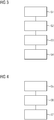
- FIG. 3 shows a flow chart, on the basis of which the method for operating the machine tool 10 is explained.
- the electronic computing device 20 receives, in particular by means of the input device 22, at least one input brought about by the person, which at least one movement of the tool 16 to be brought about by the drive and intended for processing at least the sub-area T of the workpiece 12 characterized.
- the input is characterized by so-called geometrical data, so that, for example, the electronic computing device 20 receives the geometrical data that are input by the person.
- the geometric data characterize the input and the movement that is to be carried out by the tool 16 and to be effected by means of the drive 14 in order to produce the pocket 18, for example.
- the geometric data define or characterize a length and / or a width and / or a depth of the pocket 18 to be produced.
- the geometric data characterize, for example, one along a first direction from the tool 16 relative to the first path to be covered by the workpiece 12, a second path to be covered along a second direction by the tool 16 relative to the workpiece 12 and a third path to be covered along a third direction by the tool 16 relative to the workpiece 12, the second direction being perpendicular to the first Direction and the third direction is perpendicular to the first direction and perpendicular to the second direction.
- the first path corresponds, for example, to the length of the pocket 18, the second path, for example, corresponding to the width of the pocket 18.
- the third path corresponds, for example, to the depth of the pocket 18.
- the electronic computing device 20 in particular an in FIG 1 Transmission device 26 of the electronic computing device 20, shown particularly schematically, provided transmission data which characterize the movement. These send data are in FIG 1 shown particularly schematically and denoted by 28.
- Receiving device 30 of electronic computing device 20 shown particularly schematically, receives cutting value data, in particular automatically, the cutting value data in FIG 1 are shown particularly schematically and denoted by 32.
- the cutting value data are or are from a device 34 different from the electronic computing device 20, provided in addition to the electronic computing device 20 and external to the electronic computing device 20 and to the machine tool 10 ( FIG 1 ) so that, for example, the cutting value data 32 is transmitted from the device 34 to the electronic computing device 20 and received by the electronic computing device 20.
- the device 34 is, for example, a further computing unit.
- the Transmission data 28 is transmitted, for example, from the electronic computing device 20 to the device 34 and received by the device 34, in particular by a receiving unit 36 of the device 34.
- the cutting value data are provided, for example, by the device 34 by means of a transmitting unit 38 of the device 34 and, in particular, transmitted to the electronic computing device 20.
- the cutting value data 32 are provided by the device 34 as a function of the transmitted data 28 provided and in particular received by the device 34.
- the cutting value data 32 characterize at least one cutting value for operating the machine tool 10, in particular the drive 14.
- a fourth step S4 of the method at least one value of the variable is set by means of the electronic computing device 20 as a function of the received cutting value data 32.
- the value is preferably the cut value characterized by the cut value data 32.
- the cutting value is for example a speed value of the feed or the feed and / or a speed value of the speed or the speed, so that, for example, depending on the received cutting value data 32, the aforementioned feed and / or the aforementioned speed by means of the electronic computing device 20, in particular automatically and thus, for example, is set without the active involvement of the named person.
- the tool 16 is then, for example, driven by the drive 14 as a function of the Variables, in particular depending on the set value of the variable, moved.
- FIG 3 a flow chart illustrating a method for providing cutting value data for operating the machine tool 10.
- a method for operating the machine tool 10 in particular the electronic computing device 20, is illustrated in FIG FIG 3 illustrates a method of operating device 34.
- the device 34 which is preferably designed as an electronic computing unit, receives the transmission data 28 provided by the electronic computing device 20, which contains the relative movement between the tool 16 and the workpiece 12 to be effected by means of the drive 14 and intended for processing at least the partial area T of the workpiece 12 Characterize workpiece 12.
- the cutting value for processing at least the partial area T is determined by means of the device 34 as a function of the received transmission data 28.
- the cutting value data 32 characterizing the determined cutting value is ascertained by means of the device 34, that is to say transmitted to the electronic computing device 20.
- the value, in particular the cut value, of the variables can be set in a particularly simple, time-efficient and cost-effective manner and, in particular, automatically, without the person having to make the input both into the electronic computing device 20 and into the Facility 34 must perform. In this way, the workpiece 12 can be processed in a time-saving and cost-effective manner.
Landscapes
- Engineering & Computer Science (AREA)
- Human Computer Interaction (AREA)
- Manufacturing & Machinery (AREA)
- Physics & Mathematics (AREA)
- General Physics & Mathematics (AREA)
- Automation & Control Theory (AREA)
- Numerical Control (AREA)
Priority Applications (2)
| Application Number | Priority Date | Filing Date | Title |
|---|---|---|---|
| EP19157944.0A EP3699703A1 (fr) | 2019-02-19 | 2019-02-19 | Procédé d' ajuster données de valeur de coupe pour une machine-outil |
| PCT/EP2020/052306 WO2020169317A1 (fr) | 2019-02-19 | 2020-01-30 | Procédé de réglage de données de valeur de coupe d'une machine-outil |
Applications Claiming Priority (1)
| Application Number | Priority Date | Filing Date | Title |
|---|---|---|---|
| EP19157944.0A EP3699703A1 (fr) | 2019-02-19 | 2019-02-19 | Procédé d' ajuster données de valeur de coupe pour une machine-outil |
Publications (1)
| Publication Number | Publication Date |
|---|---|
| EP3699703A1 true EP3699703A1 (fr) | 2020-08-26 |
Family
ID=65598415
Family Applications (1)
| Application Number | Title | Priority Date | Filing Date |
|---|---|---|---|
| EP19157944.0A Withdrawn EP3699703A1 (fr) | 2019-02-19 | 2019-02-19 | Procédé d' ajuster données de valeur de coupe pour une machine-outil |
Country Status (2)
| Country | Link |
|---|---|
| EP (1) | EP3699703A1 (fr) |
| WO (1) | WO2020169317A1 (fr) |
Citations (2)
| Publication number | Priority date | Publication date | Assignee | Title |
|---|---|---|---|---|
| DE112009005397T5 (de) * | 2009-11-26 | 2012-09-13 | Mitsubishi Electric Corp. | Numerische Steuervorrichtung |
| US20150277431A1 (en) * | 2014-04-01 | 2015-10-01 | The M. K. Morse Company | Saw data acquisition system and method of operating a saw |
Family Cites Families (1)
| Publication number | Priority date | Publication date | Assignee | Title |
|---|---|---|---|---|
| AT12948U1 (de) * | 2012-02-24 | 2013-02-15 | Egbert Dr Schaepermeier | Verfahren für die Zerspanung duktiler Werkstoffe mit geometrisch definierter Schneide und nach diesem Verfahren arbeitende Vorrichtungen |
-
2019
- 2019-02-19 EP EP19157944.0A patent/EP3699703A1/fr not_active Withdrawn
-
2020
- 2020-01-30 WO PCT/EP2020/052306 patent/WO2020169317A1/fr not_active Ceased
Patent Citations (2)
| Publication number | Priority date | Publication date | Assignee | Title |
|---|---|---|---|---|
| DE112009005397T5 (de) * | 2009-11-26 | 2012-09-13 | Mitsubishi Electric Corp. | Numerische Steuervorrichtung |
| US20150277431A1 (en) * | 2014-04-01 | 2015-10-01 | The M. K. Morse Company | Saw data acquisition system and method of operating a saw |
Also Published As
| Publication number | Publication date |
|---|---|
| WO2020169317A1 (fr) | 2020-08-27 |
Similar Documents
| Publication | Publication Date | Title |
|---|---|---|
| DE102019110434B4 (de) | Werkzeugwahlvorrichtung und Maschinenlernvorrichtung | |
| DE102015109362B4 (de) | Drehmagazin-Werkzeugwechsler geeignet zum Ändern einer Werkzeuglagerposition und Verfahren zum Wechseln eines Werkzeugs | |
| DE102011082291B4 (de) | Steuergerät für eine werkzeugmaschine und ein auf die zerspanung bezogenes datenverarbeitungssystem, welches mit selbiger ausgestattet ist | |
| EP1947538B1 (fr) | Procédé de commande d'un outil mobile, dispositif d'introduction tout comme machine de traitement | |
| DE102012104195A1 (de) | Steuerung für eine Werkzeugmaschine zum Schneiden von Gewinden | |
| EP2796954B1 (fr) | Commande numérique avec information d'un système CAM lors du changement du programme de pièces | |
| EP2216697A1 (fr) | Machine outil et procédé pour éviter une collision dans une machine outil | |
| DE102019100474A1 (de) | Verfahren zum Steuern einer Werkzeugmaschine und Werkzeugmaschine | |
| DE102018002683B4 (de) | Simulationsvorrichtung, programmerzeugungsvorrichtung, steuerung und anzeigeverfahren für computer | |
| DE102014016180B4 (de) | Verfahren und Einrichtung zur Verwaltung und Konfiguration von Feldgeräten einer Automatisierungsanlage | |
| DE102019204884A1 (de) | Einstellvorrichtung und Einstellprogramm | |
| DE102020133321A1 (de) | Steuervorrichtung und steuerverfahren | |
| DE102019007382A1 (de) | Numerische Steuerung | |
| DE102019007393A1 (de) | Numerische Steuerung | |
| DE112017003357T5 (de) | Auswahlvorrichtung, Auswahlverfahren und Programm | |
| EP3309635A1 (fr) | Détermination d'un programme de pièce optimisé pour une machine de traitement respective | |
| DE102019004944A1 (de) | Steuersystem einer industriemaschine | |
| DE112020006573B4 (de) | Steuerungssystem, Motorsteuerungsvorrichtung und Vorrichtung für Maschinelles Lernen | |
| DE102005025673A1 (de) | Betriebsverfahren für eine Auswertungseinrichtung für eine Produktionsmaschine | |
| EP3699703A1 (fr) | Procédé d' ajuster données de valeur de coupe pour une machine-outil | |
| DE102019106590B4 (de) | Bearbeitungsprogramm-editiervorrichtung | |
| DE112022000339B4 (de) | Numerische Steuervorrichtung | |
| DE112017003251B4 (de) | Numerische Steuerungsvorrichtung | |
| DE102019215497B4 (de) | Verfahren zum steuern einer numerisch gesteuerten werkzeugmaschine auf grundlage von ein nc-programm aufweisenden steuerdaten | |
| EP3757688B1 (fr) | Procédé de configuration d'une machine industrielle |
Legal Events
| Date | Code | Title | Description |
|---|---|---|---|
| PUAI | Public reference made under article 153(3) epc to a published international application that has entered the european phase |
Free format text: ORIGINAL CODE: 0009012 |
|
| STAA | Information on the status of an ep patent application or granted ep patent |
Free format text: STATUS: THE APPLICATION HAS BEEN PUBLISHED |
|
| AK | Designated contracting states |
Kind code of ref document: A1 Designated state(s): AL AT BE BG CH CY CZ DE DK EE ES FI FR GB GR HR HU IE IS IT LI LT LU LV MC MK MT NL NO PL PT RO RS SE SI SK SM TR |
|
| AX | Request for extension of the european patent |
Extension state: BA ME |
|
| STAA | Information on the status of an ep patent application or granted ep patent |
Free format text: STATUS: THE APPLICATION IS DEEMED TO BE WITHDRAWN |
|
| 18D | Application deemed to be withdrawn |
Effective date: 20210227 |