EP3700459B1 - Enossale zahnimplantationsanordnung - Google Patents
Enossale zahnimplantationsanordnung Download PDFInfo
- Publication number
- EP3700459B1 EP3700459B1 EP18803540.6A EP18803540A EP3700459B1 EP 3700459 B1 EP3700459 B1 EP 3700459B1 EP 18803540 A EP18803540 A EP 18803540A EP 3700459 B1 EP3700459 B1 EP 3700459B1
- Authority
- EP
- European Patent Office
- Prior art keywords
- external abutment
- screw
- dental implant
- jawbone
- anchoring foot
- Prior art date
- Legal status (The legal status is an assumption and is not a legal conclusion. Google has not performed a legal analysis and makes no representation as to the accuracy of the status listed.)
- Active
Links
Images



Classifications
-
- A—HUMAN NECESSITIES
- A61—MEDICAL OR VETERINARY SCIENCE; HYGIENE
- A61C—DENTISTRY; APPARATUS OR METHODS FOR ORAL OR DENTAL HYGIENE
- A61C8/00—Means to be fixed to the jaw-bone for consolidating natural teeth or for fixing dental prostheses thereon; Dental implants; Implanting tools
- A61C8/0018—Means to be fixed to the jaw-bone for consolidating natural teeth or for fixing dental prostheses thereon; Dental implants; Implanting tools characterised by the shape
- A61C8/0031—Juxtaosseous implants, i.e. implants lying over the outer surface of the jaw bone
Definitions
- the present invention relates to the field of endosseous dental implants and, more specifically, to the stabilization of these implants.
- endosseous implants take the form of an anchoring foot suitable for implantation in a patient's jaw bone, which anchoring foot most often corresponds to an anchoring screw.
- an anchor foot for positioning in a complementary shaped recess prepared in the jawbone of the patient also has a flange (platform) extending from the base and with which it forms therefore one and the same piece.
- this anchoring foot most often cooperates with an external pillar which is intended to be fixed in the anchoring foot and which will be coupled to a prosthetic connection making it possible to fix a crown to replace the missing dental element.
- the anchoring foot is placed "in nurseries" for a period of healing. This means that the anchor foot is placed in the bone and the gums are closed over it. In this case, no force is applied and there is no risk of mobilization of the anchor foot during the healing phase. Thus, a period of six months for a maxillary implant and three months for a mandibular implant is necessary to allow healing. During this period, all mobilization or overload on the bone leads to rejection of the anchor foot. After this healing period, the gums are opened and the prosthetic abutment is placed as well as the tooth.
- this same device has sometimes proved difficult to mount, essentially to properly center it with respect to the anchoring foot. Likewise, it may have been difficult to remove.
- the main purpose of the present invention is therefore to provide an implantation assembly having both very good stability over time without unsightly appearance and without risk of adverse consequences due to potential infections.
- the invention therefore proposes a dental implantation assembly comprising, on the one hand, an endosseous dental implant comprising at least one anchoring foot suitable for installation in a jaw bone of a patient in an endo- bone and anti-rotational means and, on the other hand, a stabilization device taking the form of a substantially rigid platform comprising (i) at least two elongated flexible lateral anchoring extensions, on either side of the central platform, so as to be able to be placed astride the bone of the jaw, pressed on either side of the latter, each extension comprising at least one orifice for positioning at least one fixing screw, (ii) a prosthetic connection, on its face opposite the jaw bone, intended to accommodate a crown and (iii) an external pillar intended to be fixed in the anchor foot, on its face resting on the jaw bone , which external pillar comprises anti-rotational means making it possible, by their association with the anti-rotational means of the endosseous dental implant, to inhibit the relative movements of the external pillar with respect to the anchor
- the substantially rigid platform forms a single component with the external abutment and/or with the prosthetic connection.
- the practitioner experiences no difficulty in fitting the stabilization device, the platform being integral with the external pillar which then acts as a means of centering the latter with respect to the anchoring foot.
- the dental implantation assembly can be used for intermediate stabilization during a so-called nurse setting phase during which the crown is not installed.
- the prosthetic connection is protected during the process of remineralization and bone reconstitution.
- the stabilization device can then, as desired and depending on the needs, be left to remains to permanently reinforce the stability of the implant or be removed and replaced by an external pillar (not associated with any platform) carrying a prosthetic connection.
- the stabilization device can be left in place or removed, and in this case replaced by an external pillar not associated with a platform, before placing the crown.
- the stabilization device in that it comprises a prominent prosthetic connection, can be easily removed, which was not known from the additional stabilization device of the prior art (the removal of the latter potentially leading to a destruction of the bone due to its difficulty of extraction).
- the stabilization device according to the invention can, if necessary, be very easily installed and uninstalled from the patient's mouth after removal of the crown.
- the anchor foot takes the form of a screw capable of being screwed into a complementary housing prepared and shaped in the maxillary bone.
- the jaw bone is then tapped so as to obtain a thread which will allow the attachment of the anchoring foot.
- the anchor foot screw may be cylindrical or conical.
- the material of the anchoring foot is advantageously compatible with the biological material of the bone in order to facilitate its osseointegration into the jaw (maxillary and mandibular bone).
- the anchor foot is made of titanium or a titanium alloy.
- the external pillar, the prosthetic connection and the platform of the stabilization device can, in pairs, be made of material, be welded or be crimped.
- the welding can be carried out by techniques well known to those skilled in the art.
- the welding of its various components can then in particular be performed by laser, friction or electronic bombardment. Preferably, this welding is carried out by laser.
- the stabilization device comprises, on its face opposite the bone and directly under the prosthetic connection, a transmucosal part.
- the height of this transmucosal part is between 0.5 and 4 mm and its diameter is between 2 and 4 mm.
- the transmucosal portion includes a widthwise constriction and may optionally also include a scallop.
- This constriction has a rounded profile, substantially parabolic and devoid of any potentially damaging angle, and forms a recessed groove.
- This groove advantageously preserves a large biological space capable of accommodating the soft tissues of the gingival mucosa and thus allowing the gums to re-form around them.
- the substantially rigid platform then forms a single component with the external pillar and the transmucosal part.
- the prosthetic connection is suitable, as desired, to accommodate a screw-retained crown or a cement-retained crown.
- the assembly of the invention further comprises: (i) a screw whose head corresponds to the prosthetic connection and which has, at its distal end, an external thread, (ii) an external pillar and, if present, a transmucosal part having an internal cavity allowing the passage of said screw but not of its head and (iii) an anchoring foot comprising an internal cavity in which a thread is formed which can cooperate with the thread of the screw to allow assembly of the assembly according to the invention by screwing the thread of the screw into the thread of the internal cavity of the anchor foot.
- this screw therefore allows assembly of the assembly according to the invention by trans-screwing.
- the screw head and the external pillar or, if present, the transmucosal part have centering means.
- these centering means are such that the screw head and the external pillar or, if present, the transmucosal part comprise complementary female and male portions.
- these complementary female and male shapes are conical shapes. Therefore, in addition to centering, these shapes make it possible, in addition to centering, to inhibit relative movements and to ensure sealing between the screw and the external pillar or, if present, the transmucosal part.
- the screw and the external pillar or, if present, the transmucosal part have complementary centering means which are included in the length of the screw and in the internal cavity of the external pillar or, if present , of the transmucosal part.
- a thread is provided within the internal cavity of the external pillar. This thread can cooperate with an external thread present on an extractor described later, so as to allow disassembly of the stabilization device from the anchoring foot.
- the elongated lateral flexible anchoring extensions associated with the central platform can be two, three, four, five, or even six or even more in number.
- Each of these branches is provided with at least one orifice for positioning a fixing screw.
- at least one of the lateral extensions is formed by a Y-shaped arm, each branch of the Y being provided with a hole for positioning a fixing screw.
- This feature is particularly important for maintaining the additional stabilization device in position.
- the Y-shape of at least one of the lateral extensions of the device allows it to follow the lines of constraints generated by the rotational and torsion movements associated with the patient's chewing.
- such a shape of the lateral extensions makes it possible to greatly limit the stresses harmful to the integrity of the stabilization device. Strong stresses on the thin arms constituting the slender extensions of the device according to the invention can in fact lead to the rupture of the lateral extensions.
- the two orifices of the branches of the same Y being separated by at least the width of the endosseous implant.
- At least one of the lateral extensions is formed by a T-shaped arm, each branch of the T being provided with an orifice for positioning a fixing screw.
- This configuration of the device which is less favorable from the point of view of the distribution of the stresses on the stabilization device, is nevertheless possible according to the invention.
- the stresses generated by the patient's mastication may in this case cause one of the arms of the T to break more easily than in the case where a Y-shaped lateral extension is used.
- the two orifices of the branches of the same Y or of the same T being separated by at least the width of the endosseous implant.
- one of the lateral extensions is longer than the other and is then intended to be fixed on the vestibular side of the jaw. This feature makes it possible to differentiate between the vestibular side and the palatal side and allows better adaptation of the additional stabilization device in the patient's mouth.
- the thickness of the substantially rigid platform is between 0.2 and 1 mm and, preferably, between 0.4 and 0.8 mm.
- the length of the substantially rigid platform is between 6 and 25 mm and, preferably, between 7 and 16 mm.
- the lengths of the lateral extensions are between 3 and 6 mm palatal and between 4 and 10 mm vestibular.
- the stabilization device and the endosseous implant having anti-rotational means such as the anchoring foot and the pillar comprise complementary female and male portions of regular polygonal shapes.
- One of the advantages of this embodiment is to ensure, by a mechanical support in abutment of two surfaces one on the other, an inhibition of the relative movements between the anchoring foot and the external pillar.
- the stabilization device and the endosseous dental implant have anti-rotational means by friction.
- the shape of the external pillar and of the anchoring foot are such that they allow them to have two anti-rotational friction surfaces in contact with one another.
- the anti-rotation means by friction are such that the anchoring foot and the pillar comprise complementary female and male portions of
- a Morse taper type connection it can be positioned either infra-crestal or juxta-crestal. To do this, we play on the height of the Morse taper which is then between 1 and 4 mm, preferably between 1.5 and 3.5 mm. As regards the angle of the connection, it is typically between 2 and 10°.
- a second object of the invention relates to a stabilization device taking the form of a substantially rigid platform as described above.
- a third object of the invention relates to a dental reconstruction prosthesis comprising a dental implantation assembly according to the invention and at least one crown capable of being assembled to said assembly, via the prosthetic connection.
- a fourth object of the invention relates to a dental implantation kit comprising a dental implantation assembly according to the invention, at least four osseointegrable screws for adjusting and fixing the dental implantation assembly on a maxillary jaw bone or mandibular.
- the kit according to the invention is characterized in that a thread is provided within the internal cavity of the external pillar and in that it further comprises an extractor (i) taking the form of a screw whose head comprises a means of gripping and/or a means of coupling with a screwing/unscrewing tool (e.g. compatible with an Allen type tool), (ii) an external thread which can cooperate with the internal thread in the internal cavity of the external pillar and (iii) whose distal end does not include any means allowing the assembly of the extractor with the anchoring foot, preferably, this distal end of the extractor bears on a surface of the internal cavity of the anchor foot.
- an extractor taking the form of a screw whose head comprises a means of gripping and/or a means of coupling with a screwing/unscrewing tool (e.g. compatible with an Allen type tool), (ii) an external thread which can cooperate with the internal thread in the internal cavity of the external pillar and (iii) whose distal end does
- the distal end of the extractor does not include any threading so as not to cooperate with the threading of the internal cavity formed at the bottom of the orifice of the anchoring foot.
- the screwing of the extractor allows the cooperation of its external thread with the thread provided within the internal cavity of the external pillar while maintaining the support of its distal end on an internal surface of the anchoring foot and this so as to allow the extraction of the external pillar and, more generally of the stabilization device, of the anchor foot of the dental implantation assembly according to the invention.
- the distal end of the extractor advantageously has a shape preventing any cooperation with the thread formed within the internal cavity of the anchoring foot.
- the distal end of the extractor has a rounded or conical shape.
- FIG. 1 schematically represents a jaw bone 1 covered with gingival tissue (2not shown).
- This bone 1 has been perforated so that an anchor foot 3 for an endosseous dental implant is introduced.
- a cavity 1' has also been made in this same bone so as to be able to accommodate a stabilization device 5 comprising an external pillar 4 surmounted by a substantially rigid central platform 6, itself surmounted by a transmucosal part 11
- the pillar 4 comprises a base 4a which constitutes a complementary male portion of a female portion 3a which is an orifice 3a made in the anchoring foot 3.
- anti-rotational means constitute anti-rotational means and make it possible to produce a mechanical link by introducing the base 4a into the orifice 3a and thus inhibiting the movements of the external pillar 4 with respect to the anchor foot 3.
- the anti-rotational means are based on the use of portions male and female forming, on the upper part, a Morse taper 3a2,4a2 respectively, surmounting a base of hexagonal section 3a1,4a1.
- Morse taper is important in that it makes it possible to ensure sealing and thus to avoid the colonization of bacteria from the implant to the bone.
- the substantially rigid platform 6 belonging to the stabilization device 5 is also represented the substantially rigid platform 6 belonging to the stabilization device 5 according to the invention.
- This stabilization device 5 comprises a substantially rigid central platform 6 associated at its center with the external pillar 4. It is understood that the installation of the stabilization device 5 formed by the substantially rigid platform 6 is greatly facilitated by the external pillar 4 which is associated with it and which acts as a means of centering with respect to the anchoring pillar 3 screwed into the bone of the jaw 1.
- the stabilizing device 5 comprises two flexible lateral anchor extensions 7.
- the pillar 4 and the transmucosal part 11 comprise a central cavity passing through them over their entire length and aligning with another internal cavity 3c made at the bottom of the orifice 3a in the anchor foot 3 when the pillar 4 is engaged in the anchor foot 3.
- These cavities are intended to receive a locking screw 12 fixing the pillar 4 to the anchor foot 3 and, by the same, the assembly of the prosthetic assembly according to the invention by trans -screwing.
- a thread is provided in the internal cavity 3c, which can cooperate with the complementary thread of the end 12a of the screw 12.
- the head of this screw 12 corresponds to the prosthetic connection 10 intended to accommodate the crown.
- the crown will be trans-screwed and, to this end, the head comprises, in addition to the prosthetic connection 10, a cavity 12b in which is provided a thread that can cooperate with the - complementary thread of a screw intended to associate the crown with him.
- the screw and the transmucosal part comprise two additional anti-rotational means (10a and 12c, 10b and 12d) both taking the form of conical male and female portions. Note that the screw 12 is shown alone in picture 3 .
- FIG 2 shows another view of the embodiment described in figure 1 and we see in particular the position of the jaw bone 1 with respect to the gingival tissue 2 which covers it.
- the anchoring foot 3 of the endosseous dental implant which perforates the bone 1.
- an external pillar (not visible in this figure) which is surmounted by a central platform 6 substantially rigid, itself surmounted by a transmucosal part 11.
- This stabilization device 5 comprises a substantially rigid central platform 6 associated at its center with the external pillar (not visible).
- the stabilization device 5 comprises two flexible anchoring lateral extensions 7 in the shape of a Y; each of the branches of the Y having a hole 8 for placing an osteointegrable screw 9.
- the spacing of the holes 8 to receive the side screws 9 for holding the stabilization device 5 will depend on the size of the -bony. It is thus noted that advantageously, the two fixing screws 9 are separated by at least the width of the endosseous implant. This attachment to the jaw bone of an element which is also part of the implant, makes it possible to very effectively reinforce the foundation of the endosseous implant in the jaw bone 1.
- the lateral extensions 7 for anchoring are such that they are intended to be placed under the gingival tissue 2, which is previously incised and raised, straddling and within the jaw bone 1, where a cavity is previously performed by the implantologist.
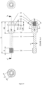
- FIG. 3 shows a first embodiment, in which the central platform 6 is associated at its center with the prosthetic connection 10 and has two lateral extensions in the form of arms 7P and 7V which each take the form of a Y and therefore comprise at the ends two branches, respectively 7Va, 7Vb and 7Pa, 7Pb.
- the arm 7V is longer than the arm 7P. This responds to an anatomical need. Indeed, it is desirable that the lateral extension 7V intended to be fixed on the side vestibular is longer than the lateral extension 7P intended to be fixed on the palatal side.
- FIG 4 represents the screw 12 allowing the assembly of the prosthetic assembly according to the invention by trans-screwing.
- the head of this screw 12 corresponds to the prosthetic connection 10 intended to accommodate the crown and the distal end 12a of the screw 12 receives a thread complementary to the thread formed in the internal cavity 3c of the anchor foot.
- Within the screw head there is also a cavity 12b in which there is an internal thread which can cooperate with the complementary threading of a screw intended to associate the crown with it by cross-screwing.
- the screw 12 comprises two inclined surfaces 12c and 12d which constitute the complementary male portions of female portions of anti-rotational means present in the internal cavity of the trans-mucous part.
- FIG. 4 represents a set of dental implantation in which the screw 12 of assembly by trans-screwing has been removed.
- an extractor 13 for the disassembly of the dental implantation assembly according to the invention.
- This extractor 13 takes the form of a screw, the head 14 of which includes a gripping means, the distal end of which does not include any thread so as not to cooperate with the tapping of the internal cavity 3c formed at the bottom of the orifice. 3a of the anchor foot 3, and which further comprises an external thread 15 which can cooperate with the internal thread 4c provided in the internal cavity of the external pillar 4.
Landscapes
- Health & Medical Sciences (AREA)
- Oral & Maxillofacial Surgery (AREA)
- Orthopedic Medicine & Surgery (AREA)
- Dentistry (AREA)
- Epidemiology (AREA)
- Life Sciences & Earth Sciences (AREA)
- Animal Behavior & Ethology (AREA)
- General Health & Medical Sciences (AREA)
- Public Health (AREA)
- Veterinary Medicine (AREA)
- Dental Prosthetics (AREA)
Claims (6)
- Dentalimplantatanordnung, umfassend:1) ein enossales Dentalimplantat, mindestens eine Verankerungswurzel (3), die für das enossale Einsetzen in einen Kieferknochen (1) eines Patienten ausgebildet ist, und Drehungen verhindernde Mittel umfassend,2) eine Stabilisierungsvorrichtung (5) in Form einer im Wesentlichen starren Plattform (6), umfassend:• mindestens zwei seitliche, längliche, flexible Verankerungsfortsätze (7) beiderseits der zentralen Plattform (6), derart, dass sie dem Kieferknochen (1) aufsitzend angeordnet werden können, diesem beiderseits anliegend, wobei jeder Fortsatz mindestens eine Öffnung (8) zum Einsetzen mindestens einer Befestigungsschraube (9) aufweist,• eine Prothesenverbindung (10) auf ihrer vom Kieferknochen (1) abgewandten Seite, dazu bestimmt, eine Krone aufzunehmen,• einen äußeren Pfeiler (4), dazu bestimmt, in der Verankerungswurzel (3) auf ihrer auf dem Kieferknochen (1) ruhenden Seite befestigt zu werden, wobei dieser äußere Pfeiler (4) Drehungen verhindernde Mittel umfasst, die in Verbindung mit den Drehungen verhindernden Mitteln des enossalen Implantats Bewegungen des äußeren Pfeilers (4) relativ zur Verankerungswurzel (3) zu verhindern erlauben, sobald der äußere Pfeiler (4) in die Verankerungswurzel (3) eingesetzt ist, und• einen transmukösen Teil (11) auf der vom Kieferknochen (1) abgewandten Seite unmittelbar unter der Prothesenverbindung (10),wobei die im Wesentlichen starre Plattform (6) mit dem äußeren Pfeiler (4), der Prothesenverbindung (10) und dem transmukösen Teil (11) ein einziges Stück bildet,3) eine ihr Zusammensetzen ermöglichende Schraube (12), deren Kopf der Prothesenverbindung (10) entspricht, wobei diese Schraube (12) den äußeren Pfeiler (4) und den transmukösen Teil (11) durchquert, und deren distales Ende gewindet ist,4) wobei der äußere Pfeiler (4) und der transmuköse Teil (11) durchbohrt sind, derart, dass das Durchtreten der Schraube (12) ermöglicht wird, und5) die Verankerungswurzel (3) einen inneren Hohlraum (3c) umfasst, in dem ein Innengewinde ausgebildet ist, das mit dem komplementären Außengewinde (12a) der genannten Schraube (12) zusammenwirken kann, um das Zusammensetzen der Dentalimplantatanordnung durch Hindurchschrauben zu erlauben,dadurch gekennzeichnet, dass ein Innengewinde im Inneren des inneren Hohlraums des äußeren Pfeilers (4) ausgebildet ist.
- Dentalimplantatanordnung nach Patentanspruch 1, dadurch gekennzeichnet, dass die Drehungen verhindernden Mittel der Verankerungswurzel (3) und des äußeren Pfeilers (4) Bereiche in Form komplementärer regelmäßiger Polygone und/oder Kegel aufweisen.
- Stabilisierungsvorrichtung (5) in Form einer im Wesentlichen starren Plattform (6), umfassend:• mindestens zwei seitliche, längliche, flexible Verankerungsfortsätze (7) beiderseits der zentralen Plattform (6), derart, dass sie dem Kieferknochen (1) aufsitzend angeordnet werden können, diesem beiderseits anliegend, wobei jeder Fortsatz mindestens eine Öffnung (8) zum Einsetzen mindestens einer Befestigungsschraube (9) aufweist,• eine Prothesenverbindung (10) auf ihrer vom Kieferknochen (1) abgewandten Seite, dazu bestimmt, eine Krone aufzunehmen,• einen äußeren Pfeiler (4), dazu bestimmt, in der Verankerungswurzel (3) auf ihrer auf dem Kieferknochen (1) ruhenden Seite befestigt zu werden, wobei dieser äußere Pfeiler (4) Drehungen verhindernde Mittel umfasst, die in Verbindung mit den Drehungen verhindernden Mitteln des enossalen Implantats Bewegungen des äußeren Pfeilers (4) relativ zur Verankerungswurzel (3) zu verhindern erlauben, sobald der äußere Pfeiler (4) in die Verankerungswurzel (3) eingesetzt ist, und• einen transmukösen Teil (11) auf der vom Kieferknochen (1) abgewandten Seite unmittelbar unter der Prothesenverbindung (10),wobei die im Wesentlichen starre Plattform (6) mit dem äußeren Pfeiler (4) und/oder der Prothesenverbindung (10) ein einziges Stück bildet,
dadurch gekennzeichnet, dass ein Innengewinde im Inneren des inneren Hohlraums des äußeren Pfeilers (4) ausgebildet ist. - Zahnersatzprothese, eine Dentalimplantatanordnung nach irgendeinem der Patentansprüche 1 bis 2 umfassend und mindestens eine Krone, die dazu geeignet ist, über die Prothesenverbindung (10) mit der genannten Anordnung zusammengefügt zu werden.
- Dentalimplantationssatz, eine Dentalimplantatanordnung nach irgendeinem der Patentansprüche 1 bis 2 umfassend und mindestens vier Knochenschrauben (9) zum Justieren und Befestigen der Dentalimplantatanordnung auf einem Ober- oder Unterkieferknochen (1),
- Satz nach Patentanspruch 5, dadurch gekennzeichnet, dass er außerdem einen Extraktor (13) umfasst,• der die Form einer Schraube hat, deren Kopf (14) ein Greiforgan und/oder Koppelorgan für ein Ein-/Ausschraubwerkzeug umfasst,• der ein Außengewinde umfasst, das mit dem Innengewinde zusammenwirken kann, das im inneren Hohlraum (4c) des äußeren Pfeilers (4) ausgebildet ist, und• dessen distales Ende keinerlei Mittel aufweist, das das Zusammensetzen des Extraktors mit der Verankerungswurzel erlaubte.
Applications Claiming Priority (2)
| Application Number | Priority Date | Filing Date | Title |
|---|---|---|---|
| FR1771114A FR3072563B1 (fr) | 2017-10-23 | 2017-10-23 | Ensemble d'implantation dentaire endo-osseux |
| PCT/EP2018/000484 WO2019081059A1 (fr) | 2017-10-23 | 2018-10-23 | Ensemble d'implantation dentaire endo-osseux |
Publications (3)
| Publication Number | Publication Date |
|---|---|
| EP3700459A1 EP3700459A1 (de) | 2020-09-02 |
| EP3700459C0 EP3700459C0 (de) | 2023-06-07 |
| EP3700459B1 true EP3700459B1 (de) | 2023-06-07 |
Family
ID=61258534
Family Applications (1)
| Application Number | Title | Priority Date | Filing Date |
|---|---|---|---|
| EP18803540.6A Active EP3700459B1 (de) | 2017-10-23 | 2018-10-23 | Enossale zahnimplantationsanordnung |
Country Status (3)
| Country | Link |
|---|---|
| EP (1) | EP3700459B1 (de) |
| FR (1) | FR3072563B1 (de) |
| WO (1) | WO2019081059A1 (de) |
Families Citing this family (3)
| Publication number | Priority date | Publication date | Assignee | Title |
|---|---|---|---|---|
| DE102018102568A1 (de) | 2018-02-06 | 2019-08-08 | Karl Leibinger Medizintechnik Gmbh & Co. Kg | Implantat mit radial erweitertem Pfosten an Trägerstruktur, Weichgewebeverdrängungssystem, Fertigungsverfahren und Planungsverfahren zum Fertigen eines Implantats |
| IT202000004753A1 (it) * | 2020-03-06 | 2021-09-06 | Ennio Calabria | Elemento posizionatore sotto-gengivale |
| FR3150705B1 (fr) * | 2023-07-07 | 2026-04-24 | Biotech Dental | Nouveau systeme de regeneration osseuse |
Citations (3)
| Publication number | Priority date | Publication date | Assignee | Title |
|---|---|---|---|---|
| WO2002074181A1 (de) * | 2001-03-19 | 2002-09-26 | Heinz-Dieter Unger | Vorrichtung zur festlegung von zahnersatz |
| US20030232308A1 (en) * | 2002-06-14 | 2003-12-18 | Simmons Earl Wayne | Method and apparatus for dental implants |
| US20110171601A1 (en) * | 2009-07-22 | 2011-07-14 | Philippe Dacremont | Additional stabilization device for endo-osseous dental implant |
-
2017
- 2017-10-23 FR FR1771114A patent/FR3072563B1/fr not_active Expired - Fee Related
-
2018
- 2018-10-23 EP EP18803540.6A patent/EP3700459B1/de active Active
- 2018-10-23 WO PCT/EP2018/000484 patent/WO2019081059A1/fr not_active Ceased
Patent Citations (3)
| Publication number | Priority date | Publication date | Assignee | Title |
|---|---|---|---|---|
| WO2002074181A1 (de) * | 2001-03-19 | 2002-09-26 | Heinz-Dieter Unger | Vorrichtung zur festlegung von zahnersatz |
| US20030232308A1 (en) * | 2002-06-14 | 2003-12-18 | Simmons Earl Wayne | Method and apparatus for dental implants |
| US20110171601A1 (en) * | 2009-07-22 | 2011-07-14 | Philippe Dacremont | Additional stabilization device for endo-osseous dental implant |
Also Published As
| Publication number | Publication date |
|---|---|
| WO2019081059A1 (fr) | 2019-05-02 |
| EP3700459C0 (de) | 2023-06-07 |
| FR3072563B1 (fr) | 2019-10-18 |
| EP3700459A1 (de) | 2020-09-02 |
| FR3072563A1 (fr) | 2019-04-26 |
Similar Documents
| Publication | Publication Date | Title |
|---|---|---|
| EP2456388B1 (de) | Ergänzende stabilisierungsvorrichtung für ein knocheninternes zahnimplantat | |
| EP2440153A1 (de) | Vorrichtung und verfahren zum halten einer prothese in der zahnimplantologie | |
| EP1613236B1 (de) | Verfahren zur reversiblen fixierung eines werkzeugs an einem implantierbaren element und vorrichtung zur durchführung dieses fixierverfahrens | |
| EP3700459B1 (de) | Enossale zahnimplantationsanordnung | |
| CH663349A5 (fr) | Structure de fixation dentaire. | |
| FR2965473A1 (fr) | Implant endo-osseux a ancrage ameliore | |
| FR2929102A1 (fr) | Perfectionnement a un implant favorisant le maintien osseux autour du col implantaire | |
| EP2117460A1 (de) | Die knochenkonservierung um den implantatkragen förderndes implantat | |
| EP2353540A1 (de) | Zahnimplantateinheit und Protheseelement | |
| EP3817689B1 (de) | Abutment- und einheilungscuff für zahnimplantat | |
| EP2685929B2 (de) | Zahnimplantat | |
| EP3251628A1 (de) | Provisorische einheilkappe für einen backenzahn, und provisorische prothese für einen backenzahn | |
| EP3478216B1 (de) | Abutment für die restaurative zahnmedizin | |
| FR2516784A1 (fr) | Nouvel implant, outil pour la mise en place de celui-ci et procede de realisations implantaires | |
| FR2766354A1 (fr) | Perfectionnements aux implants dentaires | |
| EP1961397A1 (de) | Implantateinheit zum Einsetzen in den Kieferknochen und Anlage zum Einsetzen dieser Einheit | |
| BE1021495B1 (fr) | Dispositif prothetique de reconstruction dentaire | |
| FR2931056A1 (fr) | Implant dentaire pour la realisation d'une implantation en un temps chirurgical | |
| FR2945205A1 (fr) | Ensemble prothetique dentaire. | |
| FR2969484A3 (fr) | Systeme d'implantation intra-osseux en ceramique | |
| FR3150705A1 (fr) | Nouveau systeme de regeneration osseuse | |
| FR2636832A1 (fr) | Implant pour prothese dentaire | |
| FR3010302A1 (fr) | Procede de fabrication d'un implant dentaire comportant une couche de materiau amorphe et implant dentaire obtenu selon ledit procede | |
| CA2340802A1 (fr) | Prothese obturatrice maxillo-faciale | |
| FR2886838A1 (fr) | Ensemble prothetique dentaire |
Legal Events
| Date | Code | Title | Description |
|---|---|---|---|
| STAA | Information on the status of an ep patent application or granted ep patent |
Free format text: STATUS: UNKNOWN |
|
| STAA | Information on the status of an ep patent application or granted ep patent |
Free format text: STATUS: THE INTERNATIONAL PUBLICATION HAS BEEN MADE |
|
| PUAI | Public reference made under article 153(3) epc to a published international application that has entered the european phase |
Free format text: ORIGINAL CODE: 0009012 |
|
| STAA | Information on the status of an ep patent application or granted ep patent |
Free format text: STATUS: REQUEST FOR EXAMINATION WAS MADE |
|
| 17P | Request for examination filed |
Effective date: 20200423 |
|
| AK | Designated contracting states |
Kind code of ref document: A1 Designated state(s): AL AT BE BG CH CY CZ DE DK EE ES FI FR GB GR HR HU IE IS IT LI LT LU LV MC MK MT NL NO PL PT RO RS SE SI SK SM TR |
|
| AX | Request for extension of the european patent |
Extension state: BA ME |
|
| DAV | Request for validation of the european patent (deleted) | ||
| DAX | Request for extension of the european patent (deleted) | ||
| STAA | Information on the status of an ep patent application or granted ep patent |
Free format text: STATUS: EXAMINATION IS IN PROGRESS |
|
| 17Q | First examination report despatched |
Effective date: 20210514 |
|
| GRAP | Despatch of communication of intention to grant a patent |
Free format text: ORIGINAL CODE: EPIDOSNIGR1 |
|
| STAA | Information on the status of an ep patent application or granted ep patent |
Free format text: STATUS: GRANT OF PATENT IS INTENDED |
|
| INTG | Intention to grant announced |
Effective date: 20221118 |
|
| GRAS | Grant fee paid |
Free format text: ORIGINAL CODE: EPIDOSNIGR3 |
|
| GRAA | (expected) grant |
Free format text: ORIGINAL CODE: 0009210 |
|
| STAA | Information on the status of an ep patent application or granted ep patent |
Free format text: STATUS: THE PATENT HAS BEEN GRANTED |
|
| AK | Designated contracting states |
Kind code of ref document: B1 Designated state(s): AL AT BE BG CH CY CZ DE DK EE ES FI FR GB GR HR HU IE IS IT LI LT LU LV MC MK MT NL NO PL PT RO RS SE SI SK SM TR |
|
| REG | Reference to a national code |
Ref country code: GB Ref legal event code: FG4D Free format text: NOT ENGLISH |
|
| REG | Reference to a national code |
Ref country code: CH Ref legal event code: EP Ref country code: AT Ref legal event code: REF Ref document number: 1572527 Country of ref document: AT Kind code of ref document: T Effective date: 20230615 Ref country code: DE Ref legal event code: R096 Ref document number: 602018051326 Country of ref document: DE |
|
| U01 | Request for unitary effect filed |
Effective date: 20230607 |
|
| U07 | Unitary effect registered |
Designated state(s): AT BE BG DE DK EE FI FR IT LT LU LV MT NL PT SE SI Effective date: 20230612 |
|
| REG | Reference to a national code |
Ref country code: LT Ref legal event code: MG9D |
|
| PG25 | Lapsed in a contracting state [announced via postgrant information from national office to epo] |
Ref country code: NO Free format text: LAPSE BECAUSE OF FAILURE TO SUBMIT A TRANSLATION OF THE DESCRIPTION OR TO PAY THE FEE WITHIN THE PRESCRIBED TIME-LIMIT Effective date: 20230907 Ref country code: ES Free format text: LAPSE BECAUSE OF FAILURE TO SUBMIT A TRANSLATION OF THE DESCRIPTION OR TO PAY THE FEE WITHIN THE PRESCRIBED TIME-LIMIT Effective date: 20230607 |
|
| U20 | Renewal fee for the european patent with unitary effect paid |
Year of fee payment: 6 Effective date: 20231020 |
|
| PG25 | Lapsed in a contracting state [announced via postgrant information from national office to epo] |
Ref country code: RS Free format text: LAPSE BECAUSE OF FAILURE TO SUBMIT A TRANSLATION OF THE DESCRIPTION OR TO PAY THE FEE WITHIN THE PRESCRIBED TIME-LIMIT Effective date: 20230607 Ref country code: HR Free format text: LAPSE BECAUSE OF FAILURE TO SUBMIT A TRANSLATION OF THE DESCRIPTION OR TO PAY THE FEE WITHIN THE PRESCRIBED TIME-LIMIT Effective date: 20230607 Ref country code: GR Free format text: LAPSE BECAUSE OF FAILURE TO SUBMIT A TRANSLATION OF THE DESCRIPTION OR TO PAY THE FEE WITHIN THE PRESCRIBED TIME-LIMIT Effective date: 20230908 |
|
| PG25 | Lapsed in a contracting state [announced via postgrant information from national office to epo] |
Ref country code: SK Free format text: LAPSE BECAUSE OF FAILURE TO SUBMIT A TRANSLATION OF THE DESCRIPTION OR TO PAY THE FEE WITHIN THE PRESCRIBED TIME-LIMIT Effective date: 20230607 |
|
| PGFP | Annual fee paid to national office [announced via postgrant information from national office to epo] |
Ref country code: GB Payment date: 20231026 Year of fee payment: 6 |
|
| PG25 | Lapsed in a contracting state [announced via postgrant information from national office to epo] |
Ref country code: IS Free format text: LAPSE BECAUSE OF FAILURE TO SUBMIT A TRANSLATION OF THE DESCRIPTION OR TO PAY THE FEE WITHIN THE PRESCRIBED TIME-LIMIT Effective date: 20231007 |
|
| PG25 | Lapsed in a contracting state [announced via postgrant information from national office to epo] |
Ref country code: SM Free format text: LAPSE BECAUSE OF FAILURE TO SUBMIT A TRANSLATION OF THE DESCRIPTION OR TO PAY THE FEE WITHIN THE PRESCRIBED TIME-LIMIT Effective date: 20230607 Ref country code: SK Free format text: LAPSE BECAUSE OF FAILURE TO SUBMIT A TRANSLATION OF THE DESCRIPTION OR TO PAY THE FEE WITHIN THE PRESCRIBED TIME-LIMIT Effective date: 20230607 Ref country code: RO Free format text: LAPSE BECAUSE OF FAILURE TO SUBMIT A TRANSLATION OF THE DESCRIPTION OR TO PAY THE FEE WITHIN THE PRESCRIBED TIME-LIMIT Effective date: 20230607 Ref country code: IS Free format text: LAPSE BECAUSE OF FAILURE TO SUBMIT A TRANSLATION OF THE DESCRIPTION OR TO PAY THE FEE WITHIN THE PRESCRIBED TIME-LIMIT Effective date: 20231007 Ref country code: CZ Free format text: LAPSE BECAUSE OF FAILURE TO SUBMIT A TRANSLATION OF THE DESCRIPTION OR TO PAY THE FEE WITHIN THE PRESCRIBED TIME-LIMIT Effective date: 20230607 |
|
| PGFP | Annual fee paid to national office [announced via postgrant information from national office to epo] |
Ref country code: IE Payment date: 20231109 Year of fee payment: 6 Ref country code: CH Payment date: 20231124 Year of fee payment: 6 |
|
| PG25 | Lapsed in a contracting state [announced via postgrant information from national office to epo] |
Ref country code: PL Free format text: LAPSE BECAUSE OF FAILURE TO SUBMIT A TRANSLATION OF THE DESCRIPTION OR TO PAY THE FEE WITHIN THE PRESCRIBED TIME-LIMIT Effective date: 20230607 |
|
| REG | Reference to a national code |
Ref country code: DE Ref legal event code: R097 Ref document number: 602018051326 Country of ref document: DE |
|
| PLBE | No opposition filed within time limit |
Free format text: ORIGINAL CODE: 0009261 |
|
| STAA | Information on the status of an ep patent application or granted ep patent |
Free format text: STATUS: NO OPPOSITION FILED WITHIN TIME LIMIT |
|
| 26N | No opposition filed |
Effective date: 20240308 |
|
| PG25 | Lapsed in a contracting state [announced via postgrant information from national office to epo] |
Ref country code: MC Free format text: LAPSE BECAUSE OF FAILURE TO SUBMIT A TRANSLATION OF THE DESCRIPTION OR TO PAY THE FEE WITHIN THE PRESCRIBED TIME-LIMIT Effective date: 20230607 |
|
| U20 | Renewal fee for the european patent with unitary effect paid |
Year of fee payment: 7 Effective date: 20241028 |
|
| REG | Reference to a national code |
Ref country code: CH Ref legal event code: PL |
|
| GBPC | Gb: european patent ceased through non-payment of renewal fee |
Effective date: 20241023 |
|
| PG25 | Lapsed in a contracting state [announced via postgrant information from national office to epo] |
Ref country code: GB Free format text: LAPSE BECAUSE OF NON-PAYMENT OF DUE FEES Effective date: 20241023 |
|
| PG25 | Lapsed in a contracting state [announced via postgrant information from national office to epo] |
Ref country code: CH Free format text: LAPSE BECAUSE OF NON-PAYMENT OF DUE FEES Effective date: 20241031 |
|
| PG25 | Lapsed in a contracting state [announced via postgrant information from national office to epo] |
Ref country code: CY Free format text: LAPSE BECAUSE OF FAILURE TO SUBMIT A TRANSLATION OF THE DESCRIPTION OR TO PAY THE FEE WITHIN THE PRESCRIBED TIME-LIMIT; INVALID AB INITIO Effective date: 20181023 |
|
| PG25 | Lapsed in a contracting state [announced via postgrant information from national office to epo] |
Ref country code: HU Free format text: LAPSE BECAUSE OF FAILURE TO SUBMIT A TRANSLATION OF THE DESCRIPTION OR TO PAY THE FEE WITHIN THE PRESCRIBED TIME-LIMIT; INVALID AB INITIO Effective date: 20181023 |
|
| PG25 | Lapsed in a contracting state [announced via postgrant information from national office to epo] |
Ref country code: IE Free format text: LAPSE BECAUSE OF NON-PAYMENT OF DUE FEES Effective date: 20241023 |
|
| U20 | Renewal fee for the european patent with unitary effect paid |
Year of fee payment: 8 Effective date: 20251027 |
|
| PG25 | Lapsed in a contracting state [announced via postgrant information from national office to epo] |
Ref country code: TR Free format text: LAPSE BECAUSE OF FAILURE TO SUBMIT A TRANSLATION OF THE DESCRIPTION OR TO PAY THE FEE WITHIN THE PRESCRIBED TIME-LIMIT Effective date: 20230607 |