EP3700603B1 - Brustpumpe - Google Patents
Brustpumpe Download PDFInfo
- Publication number
- EP3700603B1 EP3700603B1 EP17787438.5A EP17787438A EP3700603B1 EP 3700603 B1 EP3700603 B1 EP 3700603B1 EP 17787438 A EP17787438 A EP 17787438A EP 3700603 B1 EP3700603 B1 EP 3700603B1
- Authority
- EP
- European Patent Office
- Prior art keywords
- pump
- breastpump
- valve
- milk
- interior
- Prior art date
- Legal status (The legal status is an assumption and is not a legal conclusion. Google has not performed a legal analysis and makes no representation as to the accuracy of the status listed.)
- Active
Links
Images













Classifications
-
- A—HUMAN NECESSITIES
- A61—MEDICAL OR VETERINARY SCIENCE; HYGIENE
- A61M—DEVICES FOR INTRODUCING MEDIA INTO, OR ONTO, THE BODY; DEVICES FOR TRANSDUCING BODY MEDIA OR FOR TAKING MEDIA FROM THE BODY; DEVICES FOR PRODUCING OR ENDING SLEEP OR STUPOR
- A61M1/00—Suction or pumping devices for medical purposes; Devices for carrying-off, for treatment of, or for carrying-over, body-liquids; Drainage systems
- A61M1/06—Milking pumps
-
- A—HUMAN NECESSITIES
- A61—MEDICAL OR VETERINARY SCIENCE; HYGIENE
- A61M—DEVICES FOR INTRODUCING MEDIA INTO, OR ONTO, THE BODY; DEVICES FOR TRANSDUCING BODY MEDIA OR FOR TAKING MEDIA FROM THE BODY; DEVICES FOR PRODUCING OR ENDING SLEEP OR STUPOR
- A61M1/00—Suction or pumping devices for medical purposes; Devices for carrying-off, for treatment of, or for carrying-over, body-liquids; Drainage systems
- A61M1/06—Milking pumps
- A61M1/062—Pump accessories
- A61M1/064—Suction cups
-
- A—HUMAN NECESSITIES
- A61—MEDICAL OR VETERINARY SCIENCE; HYGIENE
- A61M—DEVICES FOR INTRODUCING MEDIA INTO, OR ONTO, THE BODY; DEVICES FOR TRANSDUCING BODY MEDIA OR FOR TAKING MEDIA FROM THE BODY; DEVICES FOR PRODUCING OR ENDING SLEEP OR STUPOR
- A61M1/00—Suction or pumping devices for medical purposes; Devices for carrying-off, for treatment of, or for carrying-over, body-liquids; Drainage systems
- A61M1/06—Milking pumps
- A61M1/062—Pump accessories
- A61M1/064—Suction cups
- A61M1/066—Inserts therefor
-
- A—HUMAN NECESSITIES
- A61—MEDICAL OR VETERINARY SCIENCE; HYGIENE
- A61M—DEVICES FOR INTRODUCING MEDIA INTO, OR ONTO, THE BODY; DEVICES FOR TRANSDUCING BODY MEDIA OR FOR TAKING MEDIA FROM THE BODY; DEVICES FOR PRODUCING OR ENDING SLEEP OR STUPOR
- A61M1/00—Suction or pumping devices for medical purposes; Devices for carrying-off, for treatment of, or for carrying-over, body-liquids; Drainage systems
- A61M1/06—Milking pumps
- A61M1/062—Pump accessories
- A61M1/067—Pump accessories with means for hands-free operation
-
- A—HUMAN NECESSITIES
- A61—MEDICAL OR VETERINARY SCIENCE; HYGIENE
- A61M—DEVICES FOR INTRODUCING MEDIA INTO, OR ONTO, THE BODY; DEVICES FOR TRANSDUCING BODY MEDIA OR FOR TAKING MEDIA FROM THE BODY; DEVICES FOR PRODUCING OR ENDING SLEEP OR STUPOR
- A61M1/00—Suction or pumping devices for medical purposes; Devices for carrying-off, for treatment of, or for carrying-over, body-liquids; Drainage systems
- A61M1/06—Milking pumps
- A61M1/069—Means for improving milking yield
- A61M1/0697—Means for improving milking yield having means for massaging the breast
-
- A—HUMAN NECESSITIES
- A61—MEDICAL OR VETERINARY SCIENCE; HYGIENE
- A61M—DEVICES FOR INTRODUCING MEDIA INTO, OR ONTO, THE BODY; DEVICES FOR TRANSDUCING BODY MEDIA OR FOR TAKING MEDIA FROM THE BODY; DEVICES FOR PRODUCING OR ENDING SLEEP OR STUPOR
- A61M1/00—Suction or pumping devices for medical purposes; Devices for carrying-off, for treatment of, or for carrying-over, body-liquids; Drainage systems
- A61M1/80—Suction pumps
-
- A—HUMAN NECESSITIES
- A61—MEDICAL OR VETERINARY SCIENCE; HYGIENE
- A61M—DEVICES FOR INTRODUCING MEDIA INTO, OR ONTO, THE BODY; DEVICES FOR TRANSDUCING BODY MEDIA OR FOR TAKING MEDIA FROM THE BODY; DEVICES FOR PRODUCING OR ENDING SLEEP OR STUPOR
- A61M39/00—Tubes, tube connectors, tube couplings, valves, access sites or the like, specially adapted for medical use
- A61M39/02—Access sites
-
- A—HUMAN NECESSITIES
- A61—MEDICAL OR VETERINARY SCIENCE; HYGIENE
- A61M—DEVICES FOR INTRODUCING MEDIA INTO, OR ONTO, THE BODY; DEVICES FOR TRANSDUCING BODY MEDIA OR FOR TAKING MEDIA FROM THE BODY; DEVICES FOR PRODUCING OR ENDING SLEEP OR STUPOR
- A61M39/00—Tubes, tube connectors, tube couplings, valves, access sites or the like, specially adapted for medical use
- A61M39/22—Valves or arrangement of valves
- A61M39/24—Check- or non-return valves
-
- A—HUMAN NECESSITIES
- A61—MEDICAL OR VETERINARY SCIENCE; HYGIENE
- A61M—DEVICES FOR INTRODUCING MEDIA INTO, OR ONTO, THE BODY; DEVICES FOR TRANSDUCING BODY MEDIA OR FOR TAKING MEDIA FROM THE BODY; DEVICES FOR PRODUCING OR ENDING SLEEP OR STUPOR
- A61M2205/00—General characteristics of the apparatus
- A61M2205/07—General characteristics of the apparatus having air pumping means
-
- A—HUMAN NECESSITIES
- A61—MEDICAL OR VETERINARY SCIENCE; HYGIENE
- A61M—DEVICES FOR INTRODUCING MEDIA INTO, OR ONTO, THE BODY; DEVICES FOR TRANSDUCING BODY MEDIA OR FOR TAKING MEDIA FROM THE BODY; DEVICES FOR PRODUCING OR ENDING SLEEP OR STUPOR
- A61M2210/00—Anatomical parts of the body
- A61M2210/10—Trunk
- A61M2210/1007—Breast; mammary
Definitions
- the present invention relates to a breast pump for expressing human breast milk.
- Devices for pumping human breast milk are well known. There are basically two different types: the first are manually operated, i.e. the vacuum required for pumping is generated by manually operating the vacuum pump. In the second type, the vacuum pump is electrically operated.
- the vacuum pumps are connected to a breast shield either directly or via a vacuum line.
- the breast shield has an interior space to accommodate the mother's breast or nipple.
- the negative pressure is transferred to the interior space via a first line, and the pumped milk flows into a milk collection container via a second line.
- US 2012/071820 A1 and WO 2016/131677 A1 each reveal a breast pump for pumping human breast milk.
- WO 2016/014494 A1 and WO 2016/014469 A1 describe a compact breast pump in which pumped milk is transported under positive pressure into a milk collection container. For this purpose, for example, a milk line is cyclically squeezed.
- WO 2011/035447 A1 discloses a breast pump in which the vacuum line simultaneously forms the milk line.
- the pumping chamber in which the negative pressure is generated fills with milk during pumping, so that the pumping system changes from a pneumatic system to a hydraulic system and the milk already pumped out Milk becomes the working fluid.
- a valve is installed at the outlet of the pump chamber, which leads to the milk collection container. This valve only opens when a certain pressure is reached within the pump chamber, ie when the pump chamber is sufficiently filled with milk.
- the system has no or almost no dead volume.
- the pump unit can be minimized because once the system is filled with milk, only a small amount of pumping power is required to pump out more milk.
- batteries with a lower capacity can be used than with pneumatic vacuum pumps.
- the vacuum pump can therefore be made smaller and more cost-effective.
- the breast pump is particularly suitable for so-called "hands-free” applications, where the breast pump is worn on the body and no hands are needed to hold the breast shield. Due to the minimized dead volume, the applied pressure can also be controlled more easily. This means that individually optimized pump parameters can be selected for each mother.
- a breast pump is also described which changes from a pneumatic to a hydraulic pumping system.
- a pressure sensor which comprises a flag attached to a flexible membrane.
- the breast pump according to the invention for pumping human breast milk comprises a pump housing with a drive unit, a Pump chamber with a flexible pump membrane driven by the drive unit for generating a vacuum and a breast shield with an interior for receiving a mother's breast.
- the interior can be subjected to a cyclically changing negative pressure by means of the pump chamber, with a milk channel leading from the interior through a first inlet opening as the first through-opening into the pump chamber, with pumped milk flowing from the interior of the breast shield through the milk channel into the pump chamber, and with the pump chamber having an outlet opening through which the pumped milk flows from the pump chamber into a milk collection container.
- a multi-part hygiene module is present, with the hygiene module having a first part with a flow opening for connection to the interior, a valve body with at least one valve and a second part with a rigid first shell for forming the pump chamber, with the valve body being arranged between the first and second parts and with the hygiene module as a whole being sealingly and detachably connectable to the pump housing of the breast pump.
- This hygiene module has a compact design. It is easy to assemble and disassemble, so that the relevant parts of the breast pump can be easily cleaned.
- the use of a valve body in the hygiene module further facilitates production, assembly and cleaning.
- the rigid first shell preferably has a milk path which leads from the pump chamber into a milk collection container and which runs perpendicular to a drive axis of the pump membrane over at least a partial area.
- the milk path preferably runs in a plane perpendicular to the drive axis, with the milk path in this plane extending over at least half the height of the pump chamber, preferably over the entire height of the pump chamber.
- the course of this milk path makes it possible to fill the pump chamber at least partially, preferably completely, with pumped milk, so that during pumping there is a change from a pneumatic pump system to a mixed or even completely hydraulic pump system.
- the valve body has at least one flow valve and one ventilation valve.
- the valve body is made in one piece from a flexible material. This makes it easier to manufacture, assemble and clean.
- the first part is part of the breast shield. This allows the breast pump to be made compact and the hygiene module can be easily attached to the breast pump without the breast shield having to be mounted additionally.
- the breast shield has a flange for detachable connection to the pump housing.
- connection to the pump housing can be made in a particularly simple manner if it is positively and force-fitting, preferably a bayonet lock.
- the outlet opening is arranged in an upper region of the pumping chamber and/or above the inlet opening in the vertical position of use of the breast pump, at least at the beginning of a pumping process.
- the pump chamber can be almost completely filled with milk and the system can be converted from a pneumatic to a hydraulic or mixed pneumatic/hydraulic system within a very short time.
- the same drive power for the pumping means e.g. the pump membrane, leads to a greater pumping power, ie to a higher negative pressure in the pump chamber and thus in the interior of the breast shield. Batteries with a lower capacity can be used. This reduces manufacturing costs and increases the service life of the pump overall. and minimizes the size of the drive unit.
- the milk channel forms a vacuum channel for applying the cyclically changing negative pressure to the interior of the breast shield.
- the vacuum is first applied via the same line or channel and then the milk is sucked out.
- the same line or channel is used for both working fluids, i.e. air and milk.
- the pump is a piston pump, a diaphragm pump or another type of vacuum pump.
- the pump chamber has a rigid first shell and a flexible pump diaphragm, whereby the pump diaphragm is in sealing contact with the rigid first shell and whereby the pump diaphragm is driven and its movement relative to the rigid first shell can generate a negative pressure in the pump chamber.
- a flexible media separation diaphragm is arranged between the rigid first shell and the flexible pump diaphragm so that the pump diaphragm is protected from contact with pumped milk. Milk and air present in the breast shield only reach the media separation diaphragm. The pump diaphragm and the other parts of the breast pump are thus protected from contamination.
- the media separation membrane can be easily separated from the pump membrane. It is part of the hygiene module mentioned above.
- the media separation membrane can preferably be separated from the other parts of the hygiene module and thus easily cleaned.
- the other parts of the hygiene module can also be separated from each other if necessary so that they can be cleaned and then easily reassembled and reused, preferably without tools.
- the rigid first shell has an outlet channel which extends from the outlet opening of the pump chamber to an outlet, wherein the outlet channel extends at least over a partial area in a direction perpendicular to the direction of movement of the pump membrane. Preferably, it extends in a plane perpendicular to this direction of movement, wherein the channel preferably extends over at least half of the Height of the pump chamber, preferably extending over the entire pump chamber.
- the channel is partially or completely designed as a closed channel.
- the pump membrane or, if present, the media separation membrane closes the outlet channel of the rigid first shell to form a channel that is closed except for the outlet opening and the outlet.
- the channel preferably extends alongside the pump chamber and not within it.
- the breast shield has a first passage opening which forms part of the milk channel, wherein the passage opening is arranged in an upper region of the interior in the position of use of the breast shield at least at the beginning of the pumping process, so that the interior below the first passage opening can be filled with pumped milk.
- the breast shield can be partially or completely filled with milk at the beginning of the pumping process. This significantly shortens the time until switching to the hydraulic pumping system. Usually the interior of the breast shield is filled first, followed by the pumping chamber, before the milk is first fed into the milk collection container.
- the milk channel can preferably be closed by means of a first valve in order to remove the pumped milk from the pump chamber at the end of the pumping process.
- This valve is preferably the same valve that opens and closes automatically when the milk is pumped. It is then permanently closed for emptying. Depending on the design, the valve is closed manually or automatically, e.g. using the electronic control of the breast pump. If a valve is arranged downstream, the first valve can also always be open during the pumping process.
- the emptying channel between the interior of the breast shield and the pumping chamber, which runs separately from the milk channel, wherein the emptying channel can be closed by means of a second valve.
- the emptying channel is closed during the pumping process and is opened at the end of the pumping process. This also takes place manually or automatically, depending on the design.
- the second valve preferably functions in the same way as or in a similar way to the first valve. It is preferably designed identically. It opens and closes during the pumping process when the breast shield is emptied, just like the first valve when the breast milk is being pumped out of the mother's breast. If a valve is arranged downstream, the second valve can also always be open during the emptying process.
- a ventilation valve to ventilate the interior of the breast shield. This is also preferably always closed during the pumping process and is opened manually or automatically to make it easier to empty the breast shield.
- the ventilation valve can be closed together with the second valve and can be opened together with the latter.
- a third valve is present which maintains a base negative pressure when the cyclically changing negative pressure in the interior of the breast shield increases.
- the pressure in the interior of the breast shield is therefore below atmospheric pressure during the entire pumping process and preferably also during emptying. This reduces the strain on the nipple and has a positive effect on the flow of milk from the mother's breast.
- a fourth valve in the milk channel, which opens and closes depending on the negative pressure applied.
- This fourth valve is arranged downstream of the first valve in the direction of pumping out the milk.
- the fourth valve can also be formed by the first valve, as already described above.
- it if it is arranged downstream, it can be designed as a flutter valve in the valve body, for example.
- a fifth valve is present in the emptying channel, which opens and closes in accordance with the applied negative pressure.
- This fifth valve is arranged downstream of the second valve in the direction of milk emptying.
- the fifth The valve can be formed by the second valve as described above. If it is arranged downstream, it can be, for example, a flutter valve in the valve body.
- valves mentioned are arranged in a common valve body. This facilitates production and minimizes costs.
- the valve body is preferably made of one piece and is flexible. It is preferably made of silicone.
- the breast pump has the pump housing with the drive unit for the pump membrane, wherein the rigid first shell is detachably connected to the pump housing. This facilitates assembly, even after cleaning by the mother.
- the rigid first shell is part of a hygiene module which can be connected together with the pump housing, wherein the hygiene module further comprises at least the valves mentioned.
- This hygiene module is preferably the hygiene module mentioned above.
- the rigid first shell is part of an adapter part, with the valve body being held in a receptacle of the adapter part. This facilitates assembly and in particular enables a modular structure and the use of a hygiene module.
- the hygiene module further comprises a manual actuating means for simultaneously actuating the first and second valves.
- the manual actuation of the two valves is a cost-effective and reliable solution.
- the adapter part and the actuating means cannot be separated from each other without causing damage. This ensures that the hygiene module is always assembled correctly and can only be used with all elements together.
- the breast pump preferably has a pump housing, wherein the breast shield can be detachably attached to the pump housing and wherein by attaching the breast shield to the pump housing, parts which lie between the breast shield and pump housing are sealed together, so that a tight connection is created between the pump chamber and the interior of the breast shield.
- the breast shield can be easily held by hand, which makes assembling the pump easier. Since the other parts also fit tightly thanks to the attachment of the breast shield to the pump housing, the breast pump is ready for use with just one movement, namely attaching the breast shield to the pump housing. The individual parts can be removed just as easily for cleaning.
- the breast shield and valve body are preferably part of the hygiene module.
- the breast pump has a pump housing to which the breast shield can be detachably attached, wherein the breast pump also has a milk collection container which can be attached to the pump housing by means of a snap fastener.
- Attaching the milk collection container by means of a snap fastener is unconventional. Twist fasteners are usually used. Thanks to the snap fastener, the container can be designed differently and, in particular, can be attached and removed more quickly.
- the milk collection container preferably has a base body and a lid, the lid being at least partially air-permeable and liquid-impermeable. This lid thus forms a valve which serves for ventilation, but which also allows the container to be turned upside down without liquid loss.
- the lid preferably has an air-permeable and liquid-impermeable membrane. The lid is preferably clamped between the milk collection container and the pump and can be positioned using spacer pins.
- the lid is preferably provided with a one-way valve that leads from the pump chamber into the milk collection container.
- the breast pump for pumping milk has human breast milk, a breast shield with an interior space for accommodating a mother's breast, and a pumping chamber, wherein the interior space can be subjected to a cyclically changing negative pressure by means of the pumping chamber.
- a milk channel leads from the interior space through a first inlet opening as the first through-opening into the pumping chamber, through which pumped milk flows from the interior space of the breast shield into the pumping chamber.
- the pumping chamber has an outlet opening through which the pumped milk flows from the pumping chamber into a milk collection container.
- An emptying channel is present between the interior space of the breast shield and the pumping chamber, which runs separately from the milk channel, wherein the emptying channel can be closed by means of a valve, wherein the emptying channel is closed during the pumping process and open at the end of the pumping process. This makes it easy to remove milk from the breast shield at the end of the pumping process.
- the emptying channel is preferably subjected to a negative pressure by means of the pump chamber in order to actively pump out the milk and force it into the milk collection container.
- the breast pump for pumping human breast milk has a breast shield with an interior for accommodating a mother's breast and a pump chamber, wherein the interior can be subjected to a cyclically changing negative pressure by means of the pump chamber.
- a milk channel leads from the interior through a first inlet opening as a first through-opening into the pump chamber, through which pumped milk flows from the interior of the breast shield into the pump chamber.
- the pump chamber has an outlet opening through which the pumped milk flows from the pump chamber into a milk collection container.
- the breast pump has a pump housing, a pump membrane and a hygiene module, wherein the hygiene module has at least one rigid first shell for forming the pump chamber and the breast shield.
- the hygiene module can be attached to the pump housing as a unit, creating a tight connection between the pump chamber and the interior of the breast shield and wherein the pump membrane is held in a sealed manner between the hygiene module and the pump housing. This makes it easier for the mother to clean the relevant parts of the breast pump and to reassemble it after such cleaning.
- the hygiene module further comprises a valve body which is arranged between breast shield and rigid first shell.
- the hygiene module further comprises a manual actuating means for actuating at least one valve of the valve structure.
- the breast pump for pumping human breast milk has a breast shield for holding a mother's breast, a pump housing and a milk collection container, wherein the pump housing can be detachably connected to the breast shield on the one hand and to the milk collection container on the other.
- the milk collection container can be attached to the pump housing by means of a snap fastener.
- this breast pump has a pumping chamber and a milk channel through which pumped milk flows from an interior of the breast shield into the pumping chamber, wherein the pumping chamber has an outlet which is connected to the milk collection container and through which the pumped milk flows into the milk collection container.
- a milk collection container for connection to a pump housing of a breast pump for pumping human breast milk, wherein the milk collection container has a lid which faces the pump housing and which is air-permeable and liquid-impermeable in at least one region.
- the breast pump for pumping human breast milk has a breast shield for receiving a mother's breast and a pump housing, wherein the breast shield can be detachably connected to the pump housing.
- the breast shield can be connected to the pump housing by means of a bayonet lock.
- a breast shield which is used for attachment to a pump housing of a breast pump.
- the breast shield has an interior for receiving the mother's breast and a nozzle for attachment to the pump housing, wherein the nozzle is provided with a bayonet closure.
- the breast pump has a breast shield with an interior for receiving a mother's breast and a pumping chamber, wherein the interior is subjected to a cyclically changing negative pressure by means of the pumping chamber.
- a first pumping phase the interior is subjected to the cyclically changing negative pressure in order to pump milk from the mother's breast, wherein the interior is filled with pumped milk without pumped milk flowing out of the interior.
- pumped milk flows from the interior into the pumping chamber and the pumping chamber is filled with pumped milk.
- a third pumping phase the pumped milk flows from the pumping chamber into a milk collection container, wherein the interior and the pumping chamber remain filled with pumped milk.
- the change from the second pumping phase to the third pumping phase occurs when a level of the pumped milk reaches an outlet opening which leads from the pumping chamber to the milk collection container, whereby milk flows through the outlet opening from the pumping chamber into the milk collection container.
- the pumping system can be converted relatively quickly from a pneumatic to a hydraulic or predominantly hydraulic pumping system. This allows smaller drives and less powerful motors to be used.
- the first pumping phase is a fully or predominantly pneumatic pumping phase and the second pumping phase is a fully or predominantly hydraulic pumping phase.
- the interior is almost completely filled in the first pumping phase.
- the interior and/or the pumping chamber are almost completely filled in the second and/or third pumping phase. completely filled with pumped milk.
- the change from the first pumping phase to the second pumping phase occurs when a level of the pumped milk reaches a first through-opening which leads from the interior to the pumping chamber, whereby milk flows through the first through-opening from the interior into the pumping chamber.
- the pumped milk flows through the first passage opening into the pumping chamber and through the outlet opening into the milk collection container.
- the interior is emptied and the milk already pumped out is led from the interior to the milk collection container through a second through-opening.
- the first passage opening can be closed with a first valve and the second passage opening can be closed with a second valve, wherein the second passage opening is always closed during the first to third pumping phases.
- the first passage opening is always closed during the fourth pumping phase.
- the second through-opening leads from the interior into the pump chamber and is in fluid communication with the outlet opening via the pump chamber.
- a base negative pressure is maintained during at least part of the pumping phases, preferably during the first, second and third pumping phases.
- a third valve is provided which first opens and then closes when the cyclically changing negative pressure increases towards atmospheric pressure, thereby maintaining the base negative pressure.
- the breast pump has a compact design. It has a pump housing 8 with a breast shield 2 attached to it and a milk collection container 9 also attached to the pump housing 8.
- a motor with a power transmission element, for example a spindle, is arranged in the pump housing 8.
- the pump housing 8 also contains at least one electronic control for controlling the motor, actuation switches 86 for actuating the pump and an energy storage device.
- the Figures 2 and 3 show an exploded view of this breast pump. It comprises the aforementioned breast shield 2 for holding the mother's breast, a valve body 3 made of a flexible material, in particular silicone, an adapter part 4, a two-part adjusting ring 5, a media separation membrane 6, a pump membrane 7, a carrier module 8', which is part of the pump housing 8, and the previously mentioned milk collection container 9.
- the milk collection container 9 can preferably be latched onto the underside of the pump housing 8, preferably it can be pivoted and releasably attached.
- Corresponding latching elements 901, 902 are in Figure 17
- the pump housing 8 has matching locking elements, which are not shown here.
- the milk collection container 9 has a vessel 90 with an interior 900 for receiving the pumped milk (see Figure 17 ).
- This vessel 90 is open at the top and can be closed with a lid.
- the lid comprises a rigid lower frame part 91, a rigid, semi-rigid or flexible cover 92 and a rigid upper frame part 93.
- the lower frame part 91 corresponds to the shape of the circumference of the opening of the vessel 90 and rests on it in a sealing manner.
- the rigid upper frame part 93 clamps the cover between the lower and upper frame parts 91, 93.
- the two frame parts 91, 93 are glued together, welded or cannot be separated from one another in another way without causing damage.
- the cover 92 is a film or other membrane-like part which is permeable to air but impermeable to liquid. Air can thus escape from the vessel 90, but no liquid can escape.
- the upper frame part 93 preferably also corresponds in its shape to the shape of the vessel 90, in particular its frame 930 corresponds to the shape of the lower frame part 91. It is in the Figures 15 and 16 shown in detail.
- struts 931 are provided to reinforce and protect the cover 92.
- a handle 933 makes it easier to lift the cover.
- Spacer pins 934 which are arranged on the frame 930 and protrude above it, ensure a distance from the pump housing 8 when the milk collecting container 9 is mounted, so that air can escape from the container interior 900 into the environment.
- a valve holder 932 is provided on the upper frame part 93 and forms the only fluid access into the interior of the vessel 90.
- a container valve 94 is arranged in this valve receptacle 932 and is designed as a one-way valve. Thus, when the lid is closed, liquid can only get into the milk collection container 9, but not out.
- the container valve 94 is preferably a duckbill valve, as shown here.
- a hygiene module according to the invention is shown. It comprises at least the nozzle 23 of the breast shield 2, the valve body 3, the adapter part 4 and the adjusting ring 5. It can also comprise, as shown here, a flexible media separation membrane 6. If the breast shield is made in one piece, it is a complete part of the hygiene module.
- the parts mentioned can be, as in the Figures 6 and 7 shown, to form a common assembly and releasably fasten them together in the carrier module 8'.
- the nozzle 23 of the breast shield 2 can preferably be fastened in a form-fitting and force-fitting manner in corresponding receptacles, here two opposing side arms 80, of the carrier module 8'.
- the connection is preferably made via a bayonet lock, as shown here.
- the nozzle 23 has a corresponding flange 22, the side arms 80 of the carrier module 8' have corresponding receptacles for the flange and the other elements of the bayonet lock.
- the intermediate parts i.e. the valve body 3, the adapter part 4 and the media separation membrane 6 of the hygiene module as well as the pump membrane 7 are also tightly connected to one another.
- the adjusting ring 5 is preferably attached to the adapter part 4 in a non-destructively detachable manner, and is pivotable relative to the adapter part 4 about the longitudinal center axis of the hygiene module.
- the breast shield 2 is shown. It is used to hold the mother's breast. It has a funnel 20 to rest on the mother's breast and an interior 200, which can be subjected to a cyclically changing negative pressure and in which the mother's breast or at least the nipple is held.
- the breast shield is preferably made in one piece and preferably from a rigid or semi-rigid plastic. However, it can also be made in several parts. It can also be used with a soft liner, e.g. with a breast shield insert made of soft silicone.
- the funnel 20 is followed by a nozzle 23 with an at least partially circumferential flange 22, which forms part of the aforementioned bayonet closure.
- the interior 200 merges on the side of the nozzle 23 facing away from the breast into a through opening 21, which forms a channel running in the central longitudinal axis.
- a through opening 21 which forms a channel running in the central longitudinal axis.
- first outlet opening 24 In the first recess, there is a first outlet opening 24 and an angled first flow opening 25.
- the first outlet opening 24 leads from the interior 200 to the outside of the nozzle 23, more precisely into the first recess.
- the first flow opening 25 leads from this first recess in a preferably rectangular channel to the free front surface of the nozzle 23 facing away from the chest.
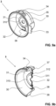
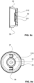
- the Figures 9a to 9d show the valve body 3.
- the valve body 3 is made of a flexible material, preferably silicone. It is preferably formed in one piece. It has a hollow cylindrical base body 30 with a rear wall 31.
- a through opening 32 is located centrally in the rear wall.
- the rear wall 31 has a ring-shaped groove 312 on the side facing away from the chest, which groove forms a sealing surface 310 on the opposite side, near the chest.
- the peripheral edge of the through opening 32 is provided with a peripheral sealing lip 311 on the side facing away from the chest (see Figures 9b and 9c ).
- the area of the rear wall 31 within the circumferential sealing surface 310 thus forms a valve which, as explained below, serves as a basic vacuum valve.
- the base body 30 has a radially protruding positioning lug 33 on the side facing the chest.
- a first nub 34 and a ventilation nub 35 are present on the casing of the base body 3.
- a second nub 36 is located diametrically opposite. The three nubs protrude radially outwards.
- the first nub 34 and the second nub 36 are solid, i.e. not hollow.
- the ventilation nub 35 has a through-opening from the interior of the base body 30 to the outside.
- valve flaps In the ring area of the rear wall 31 between the sealing surface 310 and the casing of the base body 30, there are also diametrically opposed valve flaps.
- a first of these valve flaps is provided with the reference number 37, a second of these valve flaps with the reference number 38. They are preferably located on the same diagonal as the first and second knobs 34, 36.
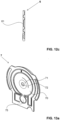
- the Figures 10a and 10b show the adjusting ring 5. It is preferably stiff and preferably made of plastic.
- the adjusting ring 5 preferably consists of two parts.
- a first part 50 has the shape of a half ring and is provided with a first plug part 51 at both free ends.
- the second part 52 also has the shape of a half ring and is provided with a second plug part 53 at each of its free ends.
- the first and two parts 50, 52 form a common ring and the two plug part pairs 51, 53 are provided with locking elements 54 in order to connect to one another preferably in a non-detachable manner.
- a first and a second pressure element 56, 57 are formed on the inner wall of the adjusting ring. These are preferably radially inwardly projecting elevations which merge via an inclined surface, also called a ramp, into a surface running parallel to the inner surface of the ring.
- An outwardly projecting actuating lever 58 is formed on the first part 50.
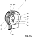
- the Figures 11a to 11c show the adapter part 4. It is preferably made of a rigid material, preferably plastic. It has a hollow cylindrical base body 40 with a substantially closed, flange-like pump-side wall 41.
- the base body 40 has a first window 400 and a diametrically opposite second window 401 in its casing.
- the pump-side wall 40 extends in a direction which is referred to here as below into a channel wall 410.
- the pump-side wall also has a raised central wall part 42 which projects into the area near the breast shield.
- a concave surface is thus formed which forms the already mentioned rigid first shell and is part of the pump chamber 47.
- a first through-opening 43 and a second through-opening 44 are present on the pump-side wall 41.
- the two through-openings 43, 44 are diametrically opposite one another. In this example, they are circular.
- a first backwash opening 45 and a second backwash opening 46 are preferably elongated. These openings all lead into the pump chamber 47.
- the concave, rigid first shell of the pump chamber 47 is surrounded by a circumferential, flat edge, which serves as a sealing surface.
- a channel 48 runs in this edge, which preferably begins at an uppermost point of the pump chamber 47 and is in fluid communication with it via an outlet opening 480.
- the channel 48 runs along the circumference of the pump chamber 47, here in a partially circular shape, downwards to an outlet 49.
- the outlet 49 is located in the channel wall 410.
- the media separation membrane 6 is shown. It is flexible, is preferably in one piece and is preferably made of silicone. It has a membrane surface 60, which is preferably provided in a known manner with at least one annular groove. A central region 61 of the membrane surface is preferably raised and faces the adapter part 4. The edge of the membrane surface 60 is designed as a sealing surface 62 and lies sealingly against the edge of the adapter part 4, whereby the pump chamber 47 is formed. A groove 63 runs within the sealing surface 62 along the circumference of the media separation membrane 6 and forms the sealing closure of the groove 48 of the adapter part 4. A recess 64 in the lower region of the media separation membrane 6 facing the pump housing serves as a free space for a pressure sensor, which is described below.
- the media separation membrane 6 preferably has, as shown in the figures, stiffeners in the form of ribs, which ensure the functioning of the media separation membrane. This means that the ribs ensure that the membrane moves in the desired manner and nevertheless always lies tightly against its adjacent parts.
- the pump membrane 7 is shown. It also has a membrane surface 70 and a central area 71. In contrast to the full-surface media separation membrane 6, the central area 71 of the pump membrane 7 is provided with a through-opening 72, the edge area of which preferably has a reinforcement 73, here in the form of ribs. There is again a circumferential sealing surface 74 which, when the device is assembled, seals against the corresponding surface of the carrier module 8'. Outside the sealing surface 74 there are side wings 77. The side wings 77 form together with the circumferential flat sealing surface 74 ( Figure 13b ) when assembled, form a tight barrier against external liquids and thus protect the electronics.
- the lower area of the pump membrane 7, which is still located within the closed circumferential sealing surface 74, is designed as a pressure sensor.
- the pressure sensor comprises a sensor surface 75 in the form of a membrane, which is connected to the membrane surface 70 via a connecting web, and a flag 76, which protrudes perpendicularly from the sensor surface in the direction of the pump housing. This type of pressure sensor is in WO 2013/049944 A1 described.
- the media separation membrane 6 and the pump membrane 7 have similar shapes, in particular with regard to their regions that can be moved to generate the negative pressure.
- the carrier module includes
- the carrier module 8' is in Figure 14 It is held in an outer casing of the pump housing.
- the outer casing is in Figure 1 visible.
- the carrier module 8' is screwed into this outer housing.
- the corresponding fastening holes are provided with the reference number 84.
- the carrier module can be made in one piece from plastic. However, it can also be made in several parts and/or from another material.
- the carrier module 8' has two protruding side arms 10 with a bayonet lock for holding the breast shield 2.
- the side arms are arranged laterally on a spindle holder 82.
- the spindle holder 82 has a Through-opening and a peripheral edge 85, which forms the counterpart to the sealing surface 74 of the pump membrane 7.
- a motor holder 81 in the form of a shell is formed on the spindle holder 82.
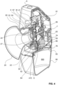
- the motor holder 81 serves to hold an electric motor, which is connected to a spindle 83 (see Figure 4 ) is connected.
- the valve body 3 can be inserted into the hollow cylindrical base body 40 of the adapter part 4 in a rotationally positioned manner.
- the adjusting ring 5 is already permanently connected to the adapter part 4, with the first pressing element 56 protruding inwards through the first window 400 and the second pressing element 57 protruding inwards through the second window 401.
- the first knob 34 of the valve body 3 is located below the first window 400 and the second knob 36 above the first window 401.
- the valve flaps 37, 38 of the valve body 3 are each located above the first and second through-openings 43, 44 of the adapter part.
- the sealing lip 311 rests sealingly on the raised wall part 42, with the first and second backwash openings being arranged in a sealed ring area between the groove 312 and the sealing lip 311.
- the first knob 34 is located over the first outlet opening 24 and the ventilation knob 35 is located over the first ventilation opening 26.
- the second knob 36 is located over the second outlet opening 27.
- the second ventilation opening 29 is covered by the casing of the valve body 4 and is thus closed.
- the spindle 83 can be seen, which drives the pump membrane 7.
- the media separation membrane 6 has a shape which fits snugly against the pump membrane 7, so that both membranes 6, 7 move together and no losses occur here either.
- the pump housing 8, more precisely the carrier module 8' has a rear wall 85, against which the pump membrane 7 rests in a sealing manner when the hygiene module is attached to the carrier module 8'. This is shown in the Figures 4 and 5 clearly visible.
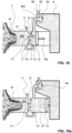
- the adjusting ring 5 is arranged so that it can pivot within the side arms 80, whereby the actuating lever 58 also serves as a display element. It moves along a display 87 which is attached to the pump housing 8 and which thus provides the user with information about the position of individual valves and thus the operating status of the pump. This means that it shows whether the pump is ready for pumping or is in the emptying state. This is explained below.
- the first ventilation opening 26 is opened and closed together with the second outlet opening 27 and the second flow opening 28.
- the second ventilation opening 29 always remains closed due to its position within the valve body 3.
- the breast shield 2 is positioned relative to the valve body 3 such that the second openings are at the position of the first openings, the second ventilation opening will of course be opened and closed instead of the first.
- the second knob 36 of the valve body 3 is pressed downwards by the second pressing element 57 of the adjusting ring and rests on the recess and thus the second outlet opening 27 and the second flow opening 28 of the breast shield 2.
- the ventilation knob 35 is pressed by the first pressing element 56 onto the first ventilation opening 26 and closes it.
- the first knob 34 of the valve body 3 is released so that the first outlet opening 24 and the first Flow opening 25 forms a fluid-communicating channel from the interior 200 of the breast shield into the base body 30 of the valve body 3. This is best done in the Figures 2 , 3 and 6 recognizable.
- the adjusting ring 5 In a second position, the adjusting ring 5 is rotated.
- the first pressing element 56 releases the ventilation knob 35 and thus the first ventilation opening 26, but presses the first knob 34 onto the recess and thus closes the first outlet opening 24 and the first flow opening 25.
- the second pressing element 57 also releases the second knob 36, so that the second outlet opening 27 and the second flow opening 28 now form an open, continuous channel from the interior 200 of the breast shield 2 into the valve body 3.
- the second outlet opening 27 and the second flow opening 28 form an emptying channel, which is described in more detail below.
- the mutual opening and closing preferably takes place simultaneously.
- the actuating lever 58 and thus the adjusting ring 5 are brought into the first position mentioned.
- the pump membrane 7 is moved together with the media separation membrane 6 back and forth to the adapter part 4, so that a negative pressure is created in the pump chamber 47 and in the interior 200 of the breast shield 2.
- the vacuum line from the pump chamber 47 into the interior 200 of the breast shield 2 is formed by the first through-opening 43 in the adapter part 4, the opening in the valve body 3 covered by the first valve flap 37 and the channel formed by the first flow opening 25 and the first outlet opening 24 in the breast shield.
- the basic vacuum valve formed among other things by the sealing lip 311 of the valve body 3, enables a basic negative pressure to be maintained in the interior 200 of the breast shield 2 when the pump stroke is directed towards atmospheric pressure.
- the basic vacuum valve opens during the pump stroke towards atmospheric pressure and only closes when a predetermined minimum pressure is reached in the interior 200. The mode of operation is explained in more detail below using a diagram.
- the air flows back into the breast shield 2 via the first and second backwash openings 45, 46 of the adapter part 4, the through opening 32 of the valve body 3 and the through opening 21 of the breast shield 2.
- the breast shield 2 is preferably held such that this first outlet opening 24 is located in an upper region of the breast shield 2.
- the pumped milk then flows through the channel formed by the first outlet opening 24 and the first passage opening 25, and through the opening covered by the first valve flap 37 into the adapter part 4, where it passes through the first passage opening 43 into the pump chamber 47.
- the pump chamber 47 also fills with milk until the outlet opening 480 arranged at the top is reached.
- the milk then flows through the channel formed by the groove 48 of the adapter part 4 and the groove 63 or the cover of the media separation membrane 6 through the outlet 49 out of the hygiene module and through the container valve 94 into the milk collection container 9.
- the base vacuum valve opens first and allows a partial backflow of the air or milk into the interior 200. This partial backflow occurs through the first and second backwash openings 45, 46, the open base vacuum valve, the through opening 32 and the through opening 21.
- the valve closes at a certain vacuum value in the interior so that the pressure cannot rise further towards atmospheric pressure.
- the milk that has already been pumped out of the mother's breast and is still in the interior 200 of the breast shield 2 is pumped through the second release opening 27, the second passage opening 28, the opening in the valve body 3 covered by the second valve flap 37 and the second passage opening 44 in the adapter part 4 into the pump chamber 47. From there it is displaced from the pump chamber 47 in the direction of the outlet opening 480 by the movement of the pump membrane 7 and the media separation membrane 6. It therefore also flows through the channel 48 and the outlet 49 into the milk collection container 9. In this way, both the interior 200 of the breast shield 2 and the pump chamber 47 can be almost completely emptied.
- the device can also be placed in an inclined position in order to empty all the milk from the system into the milk collection container 9.
- the breast pump is preferably held in such a way that the first outlet opening 24 of the breast shield and the outlet opening 480 of the pumping chamber 47 are located in an upper area of the respective hollow space.
- This allows air to escape from the system and the two hollow chambers are filled with milk relatively quickly.
- This enables the system to switch as quickly as possible from a purely pneumatic pumping system with air as the working fluid to a purely or predominantly hydraulic pumping system in which milk forms the working fluid or at least forms a large proportion of the working fluid.
- the breast pump can be placed in any position. This applies not only to the breast shield 2 and the pump chamber 47, but in particular also for the milk collection container 9. Thanks to the container valve 94 designed as a non-return valve and thanks to the liquid-tight cover 92, the milk collection container 9 can even be turned upside down without affecting the operation of the breast pump.
- the breast shield and the adjusting ring are illuminated so that the mother can carry out a visual check even at night while pumping.
- the breast shield 2 is shown schematically with the interior 200.
- the breast shield 2 is placed sealingly on a mother's breast, the nipple W protrudes into the interior 200.
- the interior 200 is connected to a pump chamber 47 via an outlet opening 16.
- An additional emptying opening 19 also leads from the interior 200 to the pump chamber 47.
- the outlet opening 16 is provided with a pump valve 12, the emptying opening with an emptying valve 14.
- a basic vacuum valve 13 closes a third opening 17 between the pump chamber 47 and the interior 200 of the breast shield 2.
- the volume of the pump chamber 47 can be changed by means of a pumping means 10, for example a pumping membrane or a piston.
- the pumping means 10 is driven, for example by means of a spindle 100.
- An outlet opening 480 leads from the pump chamber 47 into a milk collecting container 9.
- the inlet into the milk collecting container 9 is preferably provided with a check valve, here called container valve 94.
- the milk collecting container 9 is ventilated, Preferably, an inlet 95 with an inlet valve 96 is provided for this purpose.
- the outlet opening 16 and the base vacuum valve 12 of the schematic representation correspond to the first outlet opening 24, the first flow opening 25, the first nub 34, the first pressure element 56 and the first valve flap 37 of the concrete embodiment.
- the drain opening 19 and the drain valve 14 of the schematic representation correspond to the second outlet opening 27, the second flow opening 28, the second knob 36, the second pressure element 57 and the second valve flap 38 of the concrete embodiment.
- the base vacuum valve 13 and the third opening 17 of the schematic representation correspond to the sealing lip 311, the first and second backwash openings 45, 46 and the through opening 32 in the valve body 3 of the concrete embodiment.
- the container valve 94 of the schematic representation corresponds to the container valve of the concrete embodiment.
- the inlet 95 and the inlet valve 96 of the schematic representation are formed by the air-permeable and liquid-impermeable cover, i.e. by an appropriately selected cover film.
- valves can also be implemented in other ways.
- the valve openings can also be accommodated in an additional module part which is detachably connected to the breast shield.
- the outlet opening 16 and/or the emptying opening 19 can be designed as a channel which runs in a line, in particular a flexible line.
- the The pump chamber can be arranged at a distance from the breast shield and, depending on the design, also at a distance from a valve module.
- the valves can preferably be accommodated in a hygiene module which is arranged between the pump chamber and the breast shield funnel. If the pump chamber is arranged at a distance from the breast shield, the valve module can be arranged adjacent to the pump chamber or adjacent to the breast shield or can be a component of the breast shield.
- the pumping process begins and the mother's breast is stimulated by the applied negative pressure.
- the pump valve 12 can open and close.
- the first outlet opening 24 and the first flow opening 25 are exposed for this purpose and the first valve flap 37 opens and closes the valve.
- the drain valve 14 is firmly closed. In the specific embodiment, this is done by the adjusting ring 5 being brought into the appropriate position and the second outlet opening 27 and the second flow opening 28 being firmly closed.
- the ventilation valve 11 also remains firmly closed. In the specific embodiment, this is achieved by the first knob 34 closing the first ventilation opening 26 by means of the adjusting ring 5.
- the pumping means 10 preferably a pumping membrane or a piston, is pulled outwards to create a negative pressure in the pumping chamber 47 (here, for example, -150 mmHg).
- the pumping valve 12 opens and the negative pressure is transferred to the interior 200 of the breast shield 2, or air flows from this interior into the pumping chamber 47.
- a negative pressure also prevails in the interior, ideally the same pressure of, for example, -150 mmHg.
- the pressure curve in the interior 200 is in Figure 19c
- the pressure according to reference symbol a) corresponds to the pressure in the interior 200 according to Figure 19a .
- the container valve 94 remains closed.
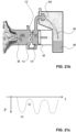
- FIGs 20a to 20c the flow of milk from the mother's breast has begun.
- the milk is marked with the reference symbol M in the figures.
- the interior 200 of the breast shield 2 fills with pumped milk.
- a lake of milk is created below the pump valve 12. Thanks to the milk now available, the pumping power increases with the drive power remaining the same, for example to -170 mmHg in the pump chamber 47 and the interior 200.
- the pump valve 12 and the basic vacuum valve 13 open and close with each pump stroke, while the emptying valve 14 and the ventilation valve 11 remain closed.
- Figure 20a shows the situation at maximum negative pressure (absolute value), which is also indicated with a) in Figure 20c is marked.
- Figure 20b shows the situation when maintaining the base negative pressure in the interior 200 and atmospheric pressure in the pump chamber 47, which in Figure 20c marked with b).
- milk M flows through the pump valve 12 into the pump chamber 47.
- the pumped milk M now also fills the pump chamber 47 until its fill level reaches the outlet opening 480 to the milk collection container 9.
- the container valve 94 now opens, preferably due to the pressure of the accumulated milk M, and milk M flows into the milk collection container 9.
- FIGS. 21a to 21c show the situation in which there is optimally no air left in the system and the original pneumatic system is completely switched to a hydraulic system.
- a mixed system is often present, with the pumped milk preferably filling a significant part of the volumes and thus forming the main working fluid.
- the pump valve 12 and the base vacuum valve 13 open and close according to the pump stroke, so that a negative pressure is generated in the interior 200 and a base negative pressure can be maintained.
- the pressure in the pump chamber 47 changes, for example, between -250 mmHg and 0 mmHg, the pressure in the interior between -250 mmHg and -20 mmHg.
- the pressure in the milk collection container 9 remains at atmospheric pressure, i.e. at 0 mmHg.
- the pump valve 12 is now firmly closed and the emptying channel and the emptying valve 14 are opened.
- the pump means 10 continues to move and generates a pressure in the pump chamber 47 that changes from a maximum negative pressure to atmospheric pressure.
- the emptying valve 14 opens and closes, as did the pump valve 12 before, and thus pumps the milk M from the interior 200 into the pump chamber 47. From there it is conveyed into the milk collection container 9, preferably first by means of negative pressure and then by displacement by the pump means 10.
- the emptying valve 14 is preferably located at a low point on the breast shield, preferably relatively far down.
- the sinking lake of milk in the interior is in the Figures 23a and 23b clearly visible.
- the Figures 23a and 23b show the two extreme situations of a pumping stroke.
- the pressure curve is in Figure 23c
- the pressure curve in the interior 200 is relatively unspecific.
- the pump is therefore still activated during emptying. If there is still milk in the pump chamber 47 at the end, it can be easily directed into the milk collection container 9 by tilting or "turning upside down” the pump.
- the breast pump according to the invention thus enables the use of pumped milk in a hydraulic pumping system, which can minimize the drive of the pump.
- REFERENCE SYMBOL LIST 32 passage opening 10 pumping agent 33 positioning mass 100 spindle 34 first pimple 11 ventilation valve 35 ventilation nub 12 pump valve 36 second pimple 13 base vacuum valve 37 first valve flap 14 drain valve 38 second valve flap 15 ventilation opening 16 outlet opening 4 adapter part 17 third opening 40 base body 19 drain opening 400 first window 401 second window 2 breast shield 402 positioning aid 20 funnel 41 pump-side wall 200 interior 410 canal wall 21 passage opening 42 raised wall section 22 flange 43 first passage opening 23 Support 44 second passage opening 24 first outlet opening 45 first backwash opening 25 first flow opening 46 second backwash opening 26 first ventilation opening 47 pump chamber 27 second outlet opening 48 gutter 28 second flow opening 480 outlet opening 29 second ventilation opening 49 outlet 3 valve body 5 adjusting ring 30 base body 50 first part 31 back wall 51 first connector part 310 sealing surface 52 second part 311 sealing lip 53 second connector part 312 groove 54 locking element 55 stop 83 spindle 56 first
Landscapes
- Health & Medical Sciences (AREA)
- Heart & Thoracic Surgery (AREA)
- Life Sciences & Earth Sciences (AREA)
- Animal Behavior & Ethology (AREA)
- Engineering & Computer Science (AREA)
- Anesthesiology (AREA)
- Biomedical Technology (AREA)
- Hematology (AREA)
- Veterinary Medicine (AREA)
- Public Health (AREA)
- General Health & Medical Sciences (AREA)
- Vascular Medicine (AREA)
- Pediatric Medicine (AREA)
- Pulmonology (AREA)
- External Artificial Organs (AREA)
- Medical Preparation Storing Or Oral Administration Devices (AREA)
- Prostheses (AREA)
Description
- Die vorliegende Erfindung betrifft eine Brustpumpe zum Abpumpen von menschlicher Muttermilch.
- Vorrichtungen zum Abpumpen von menschlicher Muttermilch sind hinlänglich bekannt. Grundsätzlich gibt es zwei verschiedene Typen: die ersten werden manuell bedient, d.h. der für das Abpumpen notwendige Unterdruck wird durch manuelle Betätigung der Vakuumpumpe erzeugt. Bei den zweiten Typen ist die Vakuumpumpe elektrisch betrieben.
- Diese Vakuumpumpen sind entweder direkt oder über eine Vakuumleitung mit einer Brusthaube verbunden. Die Brusthaube weist einen Innenraum zur Aufnahme der Mutterbrust bzw. deren Brustwarze auf. Der Unterdruck wird über eine erste Leitung in den Innenraum übertragen, die abgepumpte Milch fliesst über eine zweite Leitung in einen Milchsammelbehälter.
-
US 2012/071820 A1 undWO 2016/131677 A1 offenbaren jeweils eine Brustpumpe zum Abpumpen von menschlicher Muttermilch. -
WO 2016/014494 A1 undWO 2016/014469 A1 beschreiben eine kompakte Brustpumpe, bei welcher abgepumpte Milch unter positivem Druck in einen Milchsammelbehälter transportiert wird. Hierfür wird beispielsweise eine Milchleitung zyklisch gequetscht. -
WO 2011/035447 A1 offenbart eine Brustpumpe, bei welcher die Vakuumleitung gleichzeitig die Milchleitung bildet. Die Pumpkammer, in welcher der Unterdruck erzeugt wird, füllt sich während des Abpumpens mit Milch, so dass das Pumpsystem von einem pneumatischen System in ein hydraulisches System wechselt und die bereits abgepumpte
Milch zum Arbeitsfluid wird. Damit sich die Pumpkammer mit Milch füllen kann, ist am Ausgang der Pumpkammer, welcher zum Milchsammelbehälter fuhrt, ein Ventil angeordnet. Dieses Ventil öffnet sich erst bei einem bestimmten Druck innerhalb der Pumpkammer, d.h. wenn die Pumpkammer ausreichend mit Milch gefüllt ist. - Diese kombinierte pneumatische und hydraulische Pumpe weist mehrere Vorteile auf. Das System weist kein oder fast kein Totvolumen auf. Das Pumpaggregat kann minimiert werden, da nach Füllung des Systems mit Milch nur mehr eine geringe Pumpleistung notwendig ist, um weitere Milch abzupumpen. Insbesondere lassen sich Batterien mit geringerer Kapazität verwenden als bei pneumatischen Vakuumpumpen. Die Vakuumpumpe lässt sich somit kostengünstiger und kleiner ausbilden. Die Brustpumpe eignet sich insbesondere für sogenannte "hands-free" Anwendungen, bei welchen die Brustpumpe am Körper getragen und keine Hände zum Festhalten der Brusthaube benötigt werden. Aufgrund des minimierten Totvolumens lässt sich zudem der angelegte Druck leichter kontrollieren. Dadurch lassen sich für jede Mutter individuell optimierte Pumpparameter wählen.
- In
WO 2013/049944 A2 ist ebenfalls eine Brustpumpe beschrieben, welche von einem pneumatischen in ein hydraulisches Pumpsystem wechselt. In der Pumpkammer ist ein Drucksensor vorhanden, welcher eine an einer flexiblen Membran angebrachte Fahne umfasst. - Es ist deshalb eine Aufgabe der Erfindung, die oben genannte Brustpumpe zu optimieren.
- Diese Aufgabe löst eine Brustpumpe gemäss Anspruch 1.
- Die erfindungsgemässe Brustpumpe zum Abpumpen von menschlicher Muttermilch weist ein Pumpengehäuse mit einer Antriebseinheit, eine Pumpkammer mit einer von der Antriebseinheit angetriebenen flexiblen Pumpmembran zur Erzeugung eines Vakuums und eine Brusthaube mit einem Innenraum zur Aufnahme einer Mutterbrust auf. Der Innenraum ist mittels der Pumpkammer mit einem sich zyklisch ändernden Unterdruck beaufschlagbar, wobei ein Milchkanal vom Innenraum durch eine erste Einlassöffnung als erste Durchgangsöffnung in die Pumpkammer führt, wobei abgepumpte Milch vom Innenraum der Brusthaube durch den Milchkanal in die Pumpkammer fliesst, und wobei die Pumpkammer eine Auslassöffnung aufweist, durch welche die abgepumpte Milch von der Pumpkammer in einen Milchsammelbehälter fliesst. Ein mehrteiliges Hygienemodul ist vorhanden, wobei das Hygienemodul einen ersten Teil mit einer Durchflussöffnung zur Verbindung mit dem Innenraum, einen Ventilkörper mit mindestens einem Ventil und einen zweiten Teil mit einer steifen ersten Schale zur Bildung der Pumpkammer aufweist, wobei der Ventilkörper zwischen dem ersten und zweiten Teil angeordnet ist und wobei das Hygienemodul als Ganzes mit dem Pumpengehäuse der Brustpumpe dichtend und lösbar verbindbar ist.
- Dieses Hygienemodul ist kompakt aufgebaut. Es lässt sich einfach montieren und auseinander nehmen, so dass sich die relevanten Teile der Brustpumpe einfach reinigen lassen. Die Verwendung eines Ventilkörpers im Hygienemodul erleichtert die Herstellung, den Zusammenbau und die Reinigung zusätzlich.
- Vorzugsweise weist die steife erste Schale einen Milchpfad auf, welcher von der Pumpkammer in einen Milchsammelbehälter fühlt und welcher mindestens über einen Teilbereich senkrecht zu einer Antriebsachse der Pumpmembran verläuft. Vorzugsweise verläuft der Milchpfad in einer Ebene senkrecht zur Antriebsachse, wobei sich der Milchpfad in dieser Ebene über mindestens die Hälfte der Höhe der Pumpkammer, vorzugsweise über die gesamte Höhe der Pumpkammer erstreckt. Der Verlauf dieses Milchpfades ermöglicht es, die Pumpkammer mit abgepumpter Milch mindestens teilweise, vorzugsweise vollständig zu füllen, so dass während des Abpumpens von einem pneumatischen Pumpsystem auf ein gemischtes oder sogar vollständig hydraulisch funktionierendes Pumpsystem gewechselt wird.
- Vorzugsweise weist der Ventilkörper mindestens ein Durchflussventil und ein Belüftungsventil auf. Vorzugsweise ist der Ventilkörper einstückig aus einem flexiblen
Material gebildet. Dies erleichtert sowohl die Herstellung, wie auch den Zusammenbau und die Reinigung. - Vorzugsweise ist der erste Teil ein Bestandteil der Brusthaube. Dadurch lässt sich die Brustpumpe kompakt ausbilden und das Hygienemodul lässt sich auf einfache Art und Weise an der Brustpumpe befestigen, ohne dass zusätzlich noch die Brusthaube montiert werden muss.
- Die Brusthaube weist einen Flansch zur lösbaren Verbindung mit dem Pumpengehäuse auf.
- Die Verbindung mit dem Pumpengehäuse lässt sich auf besonders einfache Art und Weise herstellen, wenn sie form- und kraftschlüssig, vorzugsweise ein Bajonettverschluss, ist.
- In einer bevorzugten Ausführungsform ist die Auslassöffnung in vertikaler Gebrauchslage der Brustpumpe mindestens zu Beginn eines Abpumpvorgangs in einem oberen Bereich der Pumpkammer und/oder oberhalb der Einlassöffnung angeordnet.
- Dadurch lässt sich die Pumpkammer annähernd vollständig mit Milch füllen und das System kann innerhalb kürzester Zeit von einem pneumatischen in ein hydraulisches oder gemischt pneumatisch/hydraulisches System übergeführt werden. Dieselbe Antriebsleistung für die Pumpmittel, z.B. der Pumpmembran, führt zu einer grösseren Pumpleistung, d.h. zu einem betragsmässig höheren Unterdruck in der Pumpkammer und somit im Innenraum der Brusthaube. Es lassen sich Batterien mit geringerer Kapazität verwenden. Dies vermindert die Herstellungskosten, erhöht die Lebensdauer der Pumpe insgesamt und minimiert die Grösse der Antriebseinheit.
- Vorzugsweise bildet der Milchkanal einen Vakuumkanal zur Beaufschlagung des Innenraums der Brusthaube mit dem sich zyklisch ändernden Unterdruck. D.h. es wird über dieselbe Leitung bzw. über denselben Kanal zuerst das Vakuum angelegt und anschliessend die Milch abgesaugt. Dieselbe Leitung bzw. derselbe Kanal wird für beide Arbeitsfluide, d.h. Luft und Milch, verwendet.
- Je nach Ausführungsform ist die Pumpe eine Kolbenpumpe, eine Membranpumpe oder eine andere Art Vakuumpumpe. Vorzugsweise weist die Pumpkammer jedoch eine steife erste Schale und eine flexible Pumpmembran auf, wobei die Pumpmembran dichtend an der steifen ersten Schale anliegt und wobei die Pumpmembran angetrieben ist und durch deren Bewegung relativ zur steifen ersten Schale ein Unterdruck in der Pumpkammer erzeugbar ist. Vorzugsweise ist zwischen der steifen ersten Schale und der flexiblen Pumpmembran eine flexible Medientrennmembran angeordnet, so dass die Pumpmembran vor einem Kontakt mit abgepumpter Milch geschützt ist. Milch und Luft, welche in der Brusthaube vorliegen, gelangen nur bis zur Medientrennmembran. Die Pumpmembran und die übrigen Teile der Brustpumpe sind somit vor einer Kontamination geschützt.
- Die Medientrennmembran lässt sich auf einfache Art und Weise von der Pumpmembran trennen. Sie ist Teil des bereits erwähnten Hygienemoduls. Die Medientrennmembran lässt sich vorzugsweise von den übrigen Teilen des Hygienemoduls trennen und so auf einfache Art und Weise reinigen. Auch die übrigen Teile des Hygienemoduls lassen sich soweit notwendig voneinander trennen, so dass sie gereinigt und anschliessend auf einfache Art und Weise und vorzugsweise ohne Werkzeuge wieder zusammen gesetzt und erneut verwendet werden können.
- Vorzugsweise weist die steife erste Schale eine Auslassrinne auf, welche sich von der Auslassöffnung der Pumpkammer zu einem Ausgang erstreckt, wobei die Auslassrinne mindestens über einen Teilbereich in einer Richtung senkrecht zur Bewegungsrichtung der Pumpmembran verläuft. Vorzugsweise verläuft sie in einer Ebene senkrecht zu dieser Bewegungsrichtung, wobei sich die Rinne vorzugsweise über mindestens die Hälfte der
Höhe der Pumpkammer, vorzugsweise über die gesamte Pumpkammer erstreckt. - In anderen Ausführungsformen ist die Rinne teilweise oder ganz als geschlossener Kanal ausgebildet. Vorzugsweise verschliesst jedoch die Pumpmembran, oder, falls vorhanden, die Medientrennmembran die Auslassrinne der steifen ersten Schale zu einem bis auf die Auslassöffnung und den Ausgang geschlossenen Kanal.
- Die Rinne erstreckt sich vorzugsweise neben der Pumpkammer und nicht innerhalb derselben.
- In einer bevorzugten Ausführungsform weist die Brusthaube eine erste Durchlassöffnung auf, welche Teil des Milchkanals bildet, wobei die Durchlassöffnung in Gebrauchslage der Brusthaube mindestens zu Beginn des Abpumpvorgangs in einem oberen Bereich des Innenraums angeordnet ist, so dass der Innenraum unterhalb der ersten Durchlassöffnung mit abgepumpter Milch befüllbar ist.
- Dadurch lässt sich die Brusthaube zu Beginn des Abpumpvorgangs mit Milch teilweise oder ganz füllen. Dies verkürzt die Zeit bis zum Wechsel auf das hydraulische Pumpsystem nochmals massiv. Üblicherweise wird zuerst der Innenraum der Brusthaube gefüllt und anschliessend die Pumpkammer, bevor die Milch erstmals in den Milchsammelbehälter gelangt.
- Vorzugsweise ist der Milchkanal mittels eines ersten Ventils verschliessbar, um am Ende des Abpumpvorgangs die abgepumpte Milch aus der Pumpkammer zu entfernen. Dieses Ventil ist vorzugsweise dasselbe Ventil, welches sich beim Abpumpen der Milch selbsttätig öffnet und schliesst. Für die Entleerung wird es nun permanent geschlossen. Die Schliessung erfolgt je nach Ausführungsform manuell oder automatisch, z.B. mittels der elektronischen Steuerung der Brustpumpe. Ist nachfolgend ein Ventil angeordnet, so kann das erste Ventil während des Abpumpvorgangs auch stets geöffnet sein.
- Vorzugsweise ist ein Entleerungskanal zwischen dem Innenraum der Brusthaube und der Pumpkammer vorhanden, welcher getrennt vom Milchkanal verläuft, wobei der Entleerungskanal mittels eines zweiten Ventils verschliessbar ist. Der Entleerungskanal ist
während des Abpumpvorgangs geschlossen und ist am Ende des Abpumpvorgangs geöffnet. Auch dies erfolgt je nach Ausführungsform manuell oder automatisch. Das zweite Ventil funktioniert vorzugsweise gleich oder ähnlich wie das erste Ventil. Es ist vorzugsweise identisch ausgebildet. Es öffnet und schliesst sich während des Pumpvorgangs beim Entleeren der Brusthaube gleich wie das erste Ventil während des Abpumpens der Muttermilch aus der Mutterbrust. Ist nachfolgend ein Ventil angeordnet, so kann das zweite Ventil während des Entleerungsvorgangs auch stets geöffnet sein. - Vorzugsweise ist zudem ein Belüftungsventil zur Belüftung des Innenraums der Brusthaube vorhanden. Dieses ist ebenfalls vorzugsweise während des Abpumpvorgangs stets geschlossen und wird manuell oder automatisch geöffnet, um das Entleeren der Brusthaube zu erleichtern.
- Vorzugsweise ist das Belüftungsventil gemeinsam mit dem zweiten Ventil verschliessbar und es lässt sich gemeinsam mit diesem öffnen.
- In einer bevorzugten Ausführungsform ist ein drittes Ventil vorhanden, welches bei Druckanstieg des sich zyklisch ändernden Unterdrucks im Innenraum der Brusthaube einen Basisunterdruck beibehält. Der Druck im Innenraum der Brusthaube liegt somit während des gesamten Abpumpvorgangs und vorzugsweise auch während der Entleerung unter dem Atmosphärendruck. Dies vermindert die Belastung der Brustwarze und wirkt sich positiv auf den Milchfluss aus der Mutterbrust aus.
- Vorzugsweise ist im Milchkanal ein viertes Ventil vorhanden, welches sich nach Massgabe des angelegten Unterdrucks öffnet und schliesst. Dieses vierte Ventil ist in Abpumprichtung der Milch dem ersten Ventil nachfolgend angeordnet. Das vierte Ventil kann jedoch auch, wie oben bereits beschrieben, durch das erste Ventil gebildet sein. Ist es jedoch nachgeordnet, kann es beispielsweise als Flatterventil im Ventilkörper ausgebildet sein.
- Vorzugsweise ist im Entleerungskanal ein fünftes Ventil vorhanden ist, welches sich nach Massgabe des angelegten Unterdrucks öffnet und schliesst. Diese fünfte Ventil ist in Entleerungsrichtung der Milch dem zweiten Ventil nachfolgend angeordnet. Das fünfte
Ventil kann wie oben beschrieben durch das zweite Ventil gebildet sein. Ist es nachgeordnet, kann es beispielsweise ein Flatterventil im Ventilkörper sein. - Vorzugsweise ist mindestens ein Teil, vorzugsweise sind alle der genannten Ventile in einem gemeinsamen Ventilkörper angeordnet. Dies erleichtert die Herstellung und minimiert die Kosten.
- Vorzugsweise ist der Ventilkörper einstückig und flexibel ausgebildet. Vorzugsweise besteht er aus Silikon.
- Vorzugsweise weist die Brustpumpe das Pumpengehäuse mit der Antriebseinheit für die Pumpmembran auf, wobei die steife erste Schale lösbar mit dem Pumpengehäuse verbunden ist. Dies erleichtert den Zusammenbau, auch nach einer Reinigung durch die Mutter.
- Vorzugsweise ist die steife erste Schale Bestandteil eines des Hygienemoduls, welches gemeinsam mit dem Pumpengehäuse verbindbar ist, wobei das Hygienemodul des Weiteren mindestens die genannten Ventile aufweist. Dieses Hygienemodul ist vorzugsweise das oben genannte Hygienemodul.
- Vorzugsweise ist die steife erste Schale Bestandteil eines Adapterteils, wobei der Ventilkörper in einer Aufnahme des Adapterteils gehalten ist. Dies erleichtert die Montage und ermöglicht insbesondere einen modulartigen Aufbau sowie die Verwendung eines Hygienemoduls.
- Vorzugsweise umfasst das Hygienemodul ferner ein manuelles Betätigungsmittel zum zeitgleichen Betätigen des ersten und zweiten Ventils. Die manuelle Betätigung der zwei Ventile ist eine kostengünstige und betriebssichere Lösung.
- Vorzugsweise sind das Adapterteil und das Betätigungsmittel nicht zerstörungsfrei voneinander lösbar. Dadurch ist sichergestellt, dass das Hygienemodul stets korrekt zusammengestellt und nur mit sämtlichen Elementen gemeinsam verwendet werden kann.
- Vorzugsweise weist die Brustpumpe ein Pumpengehäuse auf, wobei die Brusthaube lösbar am Pumpengehäuse befestigbar ist und wobei durch die Befestigung der Brusthaube am Pumpengehäuse Teile, welche zwischen Brusthaube und Pumpengehäuse liegen, dichtend miteinander verbunden werden, so dass eine dichte Verbindung zwischen Pumpkammer und Innenraum der Brusthaube entsteht. Die Brusthaube lässt sich einfach mit der Hand halten, was den Zusammenbau der Pumpe erleichtert. Da die übrigen Teile durch die Befestigung der Brusthaube am Pumpengehäuse ebenfalls dicht anliegen, ist die Brustpumpe somit mit einem einzigen Handgriff, nämlich der Befestigung der Brusthaube am Pumpengehäuse, einsatzbereit. Ebenso einfach lassen sich die einzelnen Teile entfernen, um gereinigt zu werden. Vorzugsweise sind die Brusthaube und der Ventilkörper Teil des Hygienemoduls.
- Vorzugsweise weist die Brustpumpe ein Pumpengehäuse auf, an welchem die Brusthaube lösbar befestigbar ist, wobei die Brustpumpe ferner einen Milchsammelbehälter aufweist, welcher am Pumpengehäuse mittels eines Schnappverschlusses befestigbar ist. Die Befestigung des Milchsammelbehälters mittels eines Schnappverschlusses ist unkonventionell. Üblicherweise werden Drehverschlüsse verwendet. Dank des Schnappverschlusses lässt sich der Behälter anders ausbilden und insbesondere schneller befestigen und entfernen.
- Vorzugsweise weist der Milchsammelbehälter einen Grundkörper und einen Deckel auf, wobei der Deckel mindestens teilweise luftdurchlässig und flüssigkeitsundurchlässig ausgebildet ist. Dieser Deckel bildet somit ein Ventil, welches der Belüftung dient, welches aber auch ermöglicht, dass der Behälter ohne Flüssigkeitsverlust auf den Kopf gestellt werden kann. Vorzugsweise weist der Deckel eine luftdurchlässige und flüssigkeitsundurchlässige Membran auf. Vorzugsweise ist der Deckel zwischen dem Milchsammelbehälter und der Pumpe eingeklemmt und mittels Distanzstiften positionierbar.
- Zudem ist der Deckel vorzugsweise mit einem Einwegventil versehen, welches von der Pumpkammer in den Milchsammelbehälter führt.
- In einer bevorzugten Ausführungsform weist die Brustpumpe zum Abpumpen von menschlicher Muttermilch eine Brusthaube mit einem Innenraum zur Aufnahme einer Mutterbrust und eine Pumpkammer auf, wobei der Innenraum mittels der Pumpkammer mit einem sich zyklisch ändernden Unterdruck beaufschlagbar ist. Ein Milchkanal führt vom Innenraum durch eine erste Einlassöffnung als erste Durchgangsöffnung in die Pumpkammer, durch welchen abgepumpte Milch vom Innenraum der Brusthaube in die Pumpkammer fliesst. Die Pumpkammer weist eine Auslassöffnung auf, durch welche die abgepumpte Milch von der Pumpkammer in einen Milchsammelbehälter fliesst. Ein Entleerungskanal ist zwischen dem Innenraum der Brusthaube und der Pumpkammer vorhanden, welcher getrennt vom Milchkanal verläuft, wobei der Entleerungskanal mittels eines Ventils verschliessbar ist, wobei der Entleerungskanal während des Abpumpvorgangs geschlossen ist und am Ende des Abpumpvorgangs geöffnet ist. Dadurch lässt sich Milch am Ende des Abpumpvorgangs auf einfache Art und Weise aus der Brusthaube entfernen. Der Entleerungskanal wird vorzugsweise mittels der Pumpkammer mit einem Unterdruck beaufschlagt, um die Milch aktiv abzupumpen und in den Milchsammelbehälter zu drängen.
- In einer bevorzugten Ausführungsform weist die Brustpumpe zum Abpumpen von menschlicher Muttermilch eine Brusthaube mit einem Innenraum zur Aufnahme einer Mutterbrust und eine Pumpkammer auf, wobei der Innenraum mittels der Pumpkammer mit einem sich zyklisch ändernden Unterdruck beaufschlagbar ist. Ein Milchkanal führt vom Innenraum durch eine erste Einlassöffnung als erste Durchgangsöffnung in die Pumpkammer, durch welchen abgepumpte Milch vom Innenraum der Brusthaube in die Pumpkammer fliesst. Die Pumpkammer weist eine Auslassöffnung auf, durch welche die abgepumpte Milch von der Pumpkammer in einen Milchsammelbehälter fliesst. Die Brustpumpe weist ein Pumpengehäuse, eine Pumpmembran und ein Hygienemodul auf, wobei das Hygienemodul mindestens eine steife erste Schale zur Bildung der Pumpkammer und die Brusthaube aufweist. Das Hygienemodul ist als Einheit am Pumpengehäuse befestigbar, wobei eine dichte Verbindung zwischen der Pumpkammer und dem Innenraum der Brusthaube geschaffen wird und wobei die Pumpmembran zwischen dem Hygienemodul und dem Pumpengehäuse dichtend gehalten ist. Dies erleichtert die Reinigung der relevanten Teile der Brustpumpe durch die Mutter und den Zusammenbau nach einer derartigen Reinigung.
- Vorzugsweise weist das Hygienemodul ferner einen Ventilkörper auf, welcher zwischen Brusthaube und steifer ersten Schale angeordnet ist. Der Ventilkörper sowie die entsprechenden Bereiche des ersten und zweiten Teils, welche vorzugsweise Dichtsitze für die Ventile des Ventilkörpers aufweisen, bilden eine gemeinsame Ventileinheit, auch Ventilkonstrukt genannt.
- Vorzugsweise weist das Hygienemodul ferner ein manuelles Betätigungsmittel zur Betätigung mindestens eines Ventils des Ventilkonstrukts auf.
- In einer bevorzugten Ausführungsform weist die Brustpumpe zum Abpumpen von menschlicher Muttermilch eine Brusthaube zur Aufnahme einer Mutterbrust, ein Pumpengehäuse sowie einen Milchsammelbehälter auf, wobei das Pumpengehäuse einerseits lösbar mit der Brusthaube und andererseits lösbar mit dem Milchsammelbehälter verbindbar ist. Der Milchsammelbehälter ist mittels eines Schnappverschlusses am Pumpengehäuse befestigbar.
- Vorzugsweise weist diese Brustpumpe eine Pumpkammer und einen Milchkanal auf, durch welchen abgepumpte Milch von einem Innenraum der Brusthaube in die Pumpkammer fliesst, wobei die Pumpkammer einen Ausgang aufweist, welcher mit dem Milchsammelbehälter verbunden ist und durch welchen die abgepumpte Milch in den Milchsammelbehälter fliesst.
- In einer bevorzugten Ausführungsform ist ein Milchsammelbehälter zur Verbindung mit einem Pumpengehäuse einer Brustpumpe zum Abpumpen von menschlicher Muttermilch, vorhanden, wobei der Milchsammelbehälter einen Deckel aufweist, der dem Pumpengehäuse zugewandt ist und der mindestens in einem Bereich luftdurchlässig und flüssigkeitsundurchlässig ist.
- In einer bevorzugten Ausführungsform weist die Brustpumpe zum Abpumpen von menschlicher Muttermilch eine Brusthaube zur Aufnahme einer Mutterbrust und ein Pumpengehäuse auf, wobei die Brusthaube lösbar mit dem Pumpengehäuse verbindbar ist. Die Brusthaube ist mittels eines Bajonettverschlusses mit dem Pumpengehäuse verbindbar.
- In einer bevorzugten Ausführungsform ist eine Brusthaube vorhanden, welche zur Befestigung an einem Pumpengehäuse einer Brustpumpe dient. Die Brusthaube weist einen Innenraum zur Aufnahme der Mutterbrust und einen Stutzen zur Befestigung am Pumpengehäuse auf, wobei der Stutzen mit einem Bajonettverschluss versehen ist.
- In einer bevorzugten Variante eines Verfahrens (nicht beansprucht) zum Betätigen einer Brustpumpe zum Abpumpen von menschlicher Muttermilch weist die Brustpumpe eine Brusthaube mit einem Innenraum zur Aufnahme einer Mutterbrust und eine Pumpkammer auf, wobei der Innenraum mittels der Pumpkammer mit einem sich zyklisch ändernden Unterdruck beaufschlagt wird. In einer ersten Pumpphase wird der Innenraum mit dem sich zyklisch ändernden Unterdruck beaufschlagt, um Milch aus der Mutterbrust abzupumpen, wobei der Innenraum mit abgepumpter Milch gefüllt wird, ohne dass abgepumpte Milch aus dem Innenraum hinausfliesst. In einer zweiten Pumpphase fliesst abgepumpte Milch aus dem Innenraum in die Pumpkammer und die Pumpkammer wird mit abgepumpter Milch gefüllt. In einer dritten Pumpphase fliesst die abgepumpte Milch von der Pumpkammer in einen Milchsammelbehälter, wobei der Innenraum und die Pumpkammer mit abgepumpter Milch gefüllt bleiben. Der Wechsel von der zweiten Pumpphase zur dritten Pumpphase erfolgt, indem ein Füllstand der abgepumpten Milch eine Auslassöffnung erreicht, welche von der Pumpkammer zum Milchsammelbehälter führt, wodurch Milch durch die Auslassöffnung von der Pumpkammer in den Milchsammelbehälter fliesst.
- Dank dieses Verfahrens stellt das Pumpsystem relativ schnell von einem pneumatischen auf ein hydraulisches oder vorwiegend hydraulisches Pumpsystem um. Dadurch lassen sich kleinere Antriebe und leistungsschwächere Motoren verwenden.
- Vorzugsweise ist die erste Pumpphase eine vollständig oder vorwiegend pneumatische Pumpphase und die zweite Pumpphase eine vollständig oder vorwiegende hydraulische Pumpphase.
- In einer bevorzugten Variante des Verfahrens (nicht beansprucht) wird der Innenraum in der ersten Pumpphase annähernd vollständig gefüllt. In einer bevorzugten Variante werden der Innenraum und/oder die Pumpkammer in der zweiten und/oder dritten Pumpphase annähernd vollständig mit abgepumpter Milch gefüllt.
- Vorzugsweise erfolgt der Wechsel von der ersten Pumpphase zur zweiten Pumpphase, indem ein Füllstand der abgepumpten Milch eine erste Durchgangsöffnung erreicht, welche vom Innenraum zur Pumpkammer führt, wodurch Milch durch die erste Durchgangsöffnung vom Innenraum in die Pumpkammer fliesst.
- Vorzugsweise fliesst in der dritten Pumpphase die abgepumpte Milch durch die erste Durchgangsöffnung in die Pumpkammer und durch die Auslassöffnung in den Milchsammelbehälter.
- Vorzugsweise wird in einer vierten Pumpphase der Innenraum entleert und die darin befindliche, bereits abgepumpte Milch wird durch eine zweite Durchgangsöffnung aus dem Innenraum zum Milchsammelbehälter geführt.
- Vorzugsweise ist die erste Durchgangsöffnung mit einem ersten Ventil verschliessbar und die zweite Durchgangsöffnung mit einem zweiten Ventil verschliessbar, wobei die zweite Durchgangsöffnung während der ersten bis dritten Pumpphase stets geschlossen ist.
- Vorzugsweise ist die erste Durchgangsöffnung während der vierten Pumpphase stets geschlossen.
- Vorzugweise führt die zweite Durchgangsöffnung vom Innenraum in die Pumpkammer und steht über die Pumpkammer in fluidkommunizierender Verbindung mit der Auslassöffnung.
- Vorzugsweise wird während mindestens einem Teil der Pumpphasen, vorzugsweise während der ersten, zweiten und dritten Pumpphase ein Basisunterdruck beibehalten.
- Vorzugsweise ist ein drittes Ventil vorhanden, welches bei Druckanstieg des sich zyklisch ändernden Unterdrucks in Richtung Atmosphärendruck zuerst öffnet und dann schliesst und dadurch den Basisunterdruck beibehält.
- Die einzelnen in den Ansprüchen aufgeführten Elemente lassen sich auch zu anderen Kombinationen zusammenfügen, ohne dass sämtliche Merkmale der Ansprüche übernommen werden müssen. Insbesondere lassen sich einzelne Elemente auch in reinen pneumatischen Brustpumpen verwenden, insbesondere in pneumatischen Membran- Brustpumpen.
- Bevorzugte Ausführungsformen der Erfindung werden im Folgenden anhand der Zeichnungen beschrieben, die lediglich zur Erläuterung dienen und nicht einschränkend auszulegen sind. In den Zeichnungen zeigen:
-
Figur 1 eine perspektivische Darstellung einer erfmdungsgemässen Brustpumpe, -
Figur 2 eine Explosionsdarstellung der Brustpumpe gemässFigur 1 in einer perspektivischen Ansicht; -
Figur 3 eine Explosionsdarstellung der Brustpumpe gemässFigur 1 in einer weiteren perspektivischen Ansicht; -
Figur 4 einen Teilschnitt durch die Brustpumpe gemässFigur 1 in einer ersten perspektivischen Ansicht; -
Figur 5 einen Teilschnitt durch die Brustpumpe gemässFigur 1 in einer zweiten perspektivischen Ansicht; -
Figur 6 einen Längsschnitt durch ein Hygienemodul, befestigt an einem Trägermodul der Brustpumpe gemässFigur 1 in Explosionsdarstellung; -
Figur 7 eine perspektivische Darstellung des zusammengesetzten Hygienemodul gemässFigur 6 ; -
Figur 8a eine perspektivische Darstellung einer Brusthaube der Brustpumpe gemässFigur 1 ; -
Figur 8b einen Teilschnitt durch die Brusthaube gemässFigur 8a ; -
Figur 9a eine perspektivische Darstellung durch einen Ventilkörper der Brustpumpe gemässFigur 1 ; -
Figur 9b einen Teilschnitt durch den Ventilkörper gemässFigur 9a ; -
Figur 9c einen Längsschnitt durch den Ventilkörper gemässFigur 9a ; -
Figur 9d eine Ansicht des Ventilkörpers gemässFigur 9a ; -
Figur 10a eine perspektivische Darstellung eines Stellrings der Brustpumpe gemässFigur 1 ; -
Figur 10b eine Ansicht des Stellrings gemässFigur 10a ; -
Figur 11a eine perspektivische Darstellung eines Adapterteils der Brustpumpe gemäss -
Figur 1 von einer ersten Seite; -
Figur 11b einen Teilschnitt durch das Adapterteil gemäss Figur I Ia; -
Figur 11c eine perspektivische Darstellung des Adapterteils gemäss Figur I Ia von einer zweiten Seite; -
Figur 12a eine perspektivische Darstellung einer Medientrennmembran der Brustpumpe gemässFigur 1 von einer ersten Seite; -
Figur 12b eine perspektivische Darstellung der Medientrennmembran gemässFigur 12a von einer zweiten Seite; -
Figur 12c einen Längsschnitt durch die Medientrennmembran gemässFigur 12a ;Figur 13a eine perspektivische Darstellung einer Pumpmembran der Brustpumpe gemässFigur 1 von einer ersten Seite; -
Figur 13b eine perspektivische Darstellung der Pumpmembran gemässFigur 13a von einer zweiten Seite;Figur 13c einen Längsschnitt durch die Pumpmembran gemässFigur 13a ; -
Figur 14 eine perspektivische Darstellung eines Trägermoduls der Brustpumpe gemässFigur 1 ; -
Figur 15 eine perspektivische Darstellung eines oberen Rahmenteils eines Milchsammelbehälters der Brustpumpe gemässFigur 1 ; -
Figur 16 einen Längsschnitt durch das obere Rahmenteil gemässFigur 15 mit einem Behälterventil; -
Figur 17 eine perspektivische Darstellung eines Gefässes des Milchsammelbehälters der Brustpumpe gemässFigur 1 ;Figur 18 eine schematische Darstellung des erfmdungsgemässen Pumpsystems vor Anlegen eines Unterdrucks; -
Figur 19a das schematisch dargestellte Pumpsystem gemässFigur 1 bei der Aktivierung der Mutterbrust in einer ersten Hubposition; -
Figur 19b das Pumpsystem gemässFigur 19a in einer zweiten Hubposition; -
Figur 19c eine grafische Darstellung des Drucks innerhalb einer Brusthaube beim Wechsel von der ersten Hubposition in die zweite Hubposition gemäss denFiguren 19a und19b ;Figur 20a das Pumpsystem gemässFigur 19a zu Beginn des Milchflusses aus der Brust in einer ersten Hubposition; -
Figur 20b das Pumpsystem gemässFigur 20a in einer zweiten Hubposition; -
Figur 20c eine grafische Darstellung des Drucks innerhalb einer Brusthaube beim Wechsel von der ersten Hubposition in die zweite Hubposition gemäss denFiguren 20a und 20b ; -
Figur 21a das Pumpsystem gemässFigur 19a während des kontinuierlichen Milchflusses aus der Brust in einer ersten Hubposition;Figur 21b das Pumpsystem gemässFigur 21 a in einer zweiten Hubposition; -
Figur 21c eine grafische Darstellung des Drucks innerhalb einer Brusthaube beim Wechsel von der ersten Hubposition in die zweite Hubposition gemäss denFiguren 21a und21b ; -
Figur 22a das Pumpsystem gemässFigur 19a bei Beendigung des Milchflusses in einer ersten Hubposition; -
Figur 22b das Pumpsystem gemässFigur 22a in einer zweiten Hubposition; -
Figur 22c eine grafische Darstellung des Drucks innerhalb einer Brusthaube beim Wechsel von der ersten Hubposition in die zweite Hubposition gemäss denFiguren 22a und 22b ; -
Figur 23 a das Pumpsystem gemässFigur 19a beim Entleeren in einer ersten Hubposition; -
Figur 23 b das Pumpsystem gemässFigur 23 a in einer zweiten Hubposition undFigur 23c eine grafische Darstellung des Drucks innerhalb einer Brusthaube beim Wechsel von der ersten Hubposition in die zweite Hubposition gemäss denFiguren 23a und23b . - In den
Figuren 1 bis 17 ist ein bevorzugtes Ausführungsbeispiel der erfmdungsgemässen Brustpumpe dargestellt. - Wie in
Figur 1 erkennbar ist, ist die Brustpumpe kompakt aufgebaut. Sie weist ein Pumpengehäuse 8 mit einer daran befestigten Brusthaube 2 und einem ebenfalls am Pumpengehäuse 8 befestigten Milchsammelbehälter 9 auf. Im Pumpengehäuse 8 ist ein Motor mit einem Kraftübertragungselement, beispielsweise eine Spindel, angeordnet. Im Pumpengehäuse 8 sind ferner mindestens eine elektronische Steuerung zur Steuerung des Motors, Betätigungsschalter 86 zur Betätigung der Pumpe und ein Energiespeicher vorhanden. - Die
Figuren 2 und3 zeigen eine Explosionsdarstellung dieser Brustpumpe. Sie umfasst die erwähnte Brusthaube 2 zur Aufnahme der Mutterbrust, einen Ventilkörper 3 aus einem flexiblen Material, insbesondere Silikon, ein Adapterteil 4, einen zweiteiligen Stellring 5, eine Medientrennmembran 6, eine Pumpmembran 7, ein Trägermodul 8', welches Teil des Pumpengehäuses 8 ist sowie den bereits erwähnten Milchsammelbehälter 9. - Der Milchsammelbehälter 9 ist vorzugsweise auf der Unterseite des Pumpengehäuses 8 an dieses einklinkbar, vorzugsweise lässt es einschwenkbar lösbar befestigen. Entsprechende Einrastelement 901 , 902 sind in
Figur 17 erkennbar. Das Pumpengehäuse 8 weist dazu passende, jedoch hier nicht dargestellte Einrastelemente auf. - Der Milchsammelbehälter 9 weist ein Gefäss 90 mit einem Innenraum 900 zur Aufnahme der abgepumpten Milch auf (siehe
Figur 17 ). Dieses Gefäss 90 ist oben offen ausgebildet und mit einem Deckel verschliessbar. Der Deckel umfasst ein steifes unteres Rahmenteil 91, eine steife, halbsteife oder flexible Abdeckung 92 und ein steifes oberes Rahmenteil 93. Das untere Rahmenteil 91 entspricht der Form des Umfangs der Öffnung des Gefässes 90 und liegt dichtend auf diesem auf. Das steife obere Rahmenteil 93 klemmt die Abdeckung zwischen unterem und oberen Rahmenteil 91, 93 ein. Vorzugsweise sind die zwei Rahmenteile 91, 93 miteinander verleimt, verschweisst oder auf andere Art und Weise nicht zerstörungsfrei voneinander lösbar. Die Abdeckung 92 ist eine Folie oder ein anderes membranähnliches Teil, welche luftdurchlässig aber flüssigkeitsundurchlässig ist. Somit kann Luft aus dem Gefäss 90 entweichen, jedoch keine Flüssigkeit austreten. - Das obere Rahmenteil 93 entspricht vorzugsweise ebenfalls in seiner Form der Form des Gefässes 90, insbesondere entspricht sein Rahmen 930 der Form des unteren Rahmenteils 91. Es ist in den
Figuren 15 und16 detailliert dargestellt. Im Rahmen 930 sind zur Verstärkung und als Schutz der Abdeckung 92 Streben 931 vorhanden. Ein Griff 933 erleichtert das Anheben des Deckels. Distanzstifte 934, welche auf dem Rahmen 930 angeordnet sind und diesen überragen, gewährleisten bei montiertem Milchsammelbehälter 9 einen Abstand zum Pumpengehäuse 8, so dass Luft aus dem Behälterinnenraum 900 in die Umgebung entweichen kann. Eine Ventilaufnahme 932 ist am oberen Rahmenteil 93 angeformt und bildet den einzigen Flüssigkeitszugang in den Innenraum des Gefässes 90. - In dieser Ventilaufnahme 932 ist ein Behälterventil 94 angeordnet, welches als Einwegventil ausgebildet ist. Somit kann bei geschlossenem Deckel Flüssigkeit nur in den Milchsammelbehälter 9 hinein gelangen, nicht jedoch hinaus. Das Behälterventil 94 ist vorzugsweise, wie hier dargestellt, ein Entenschnabelventil.
- In den
Figuren 6 und 7 ist ein erfindungsgemässes Hygienemodul dargestellt. Es umfasst mindestens den Stutzen 23 der Brusthabe 2, den Ventilkörper 3, das Adapterteil 4 sowie den Stellring 5. Es kann zudem, wie hier dargestellt ist, auch eine flexible Medientrennmembran 6 umfassen. Ist die Brusthaube einstückig ausgeführt, so ist sie gesamthaft Teil des Hygienemoduls. - Die genannten Teile lassen sich, wie in den
Figuren 6 und 7 dargestellt, zu einer gemeinsamen Baugruppe zusammenfügen und gemeinsam im Trägermodul 8' lösbar befestigen. Hierfür ist der Stutzen 23 der Brusthaube 2 vorzugsweise form- und kraftschlüssig in entsprechende Aufnahmen, hier zwei einander gegenüberliegende Seitenarme 80, des Trägermoduls 8' befestigbar. Vorzugsweise erfolgt die Verbindung über einen Bajonettverschluss, wie hier dargestellt ist. Der Stutzen 23 weist einen entsprechenden Flansch 22 auf, die Seitenarme 80 des Trägermoduls 8' entsprechende Aufnahmen für den Flansch und die übrigen Elemente des Bajonettverschlusses. - Dank der Befestigung der Brusthaube am Trägermodul 8' und somit am Pumpengehäuse 8 sind auch die dazwischenliegenden Teile, d.h. der Ventilkörper 3, das Adapterteil 4 und die Medientrennmembran 6 des Hygienemoduls sowie die Pumpmembran 7 miteinander dicht verbunden.
- Der Stellring 5 ist vorzugsweise nicht zerstörungsfrei lösbar auf dem Adapterteil 4 befestigt, wobei er relativ zu diesem um die Längsmittelachse des Hygienemoduls schwenkbar ist.
- Im Folgenden werden die einzelnen Teile der Vorrichtung und deren Zusammenwirken beschrieben.
- In den
Figuren 8a und 8b ist die Brusthaube 2 dargestellt. Sie dient zur Aufnahme der Mutterbrust. Sie weist einen Trichter 20 zur Auflage auf die Mutterbrust und einen Innenraum 200 auf, welcher mit einem sich zyklisch ändernden Unterdruck beaufschlagbar ist und in welchem die Mutterbrust oder zumindest die Brustwarze aufgenommen wird. Die Brusthaube ist vorzugsweise einstückig und vorzugsweise aus einem steifen oder halbsteifen Kunststoff gefertigt. Sie kann jedoch auch mehrteilig ausgeführt sein. Sie kann zudem mit einem weichen Liner verwendet werden, z.B. mit einem Brusthaubeneinsatz aus einem weichen Silikon. Der Trichter 20 folgt ein Stutzen 23 mit einem mindestens teilweise umlaufenden Flansch 22, welcher einen Teil des genannten Bajonettverschlusses bildet. Der Innenraum 200 geht auf der brustabgewandten Seite des Stutzens 23 in eine Durchgangsöffnung 21 über, welche einen in der Mittellängsachse verlaufenden Kanal bildet. Am Stutzen 23, auf der brustabgewandten Seite des Flansches 22 ist, ist auf zwei diametral gegenüberliegenden Seiten je eine Vertiefung vorhanden. - In der ersten Vertiefung ist eine erste Auslassöffnung 24 sowie eine winkelförmige erste Durchflussöffnung 25 vorhanden. Die erste Auslassöffnung 24 führt vom Innenraum 200 zur Aussenseite des Stutzens 23, genauer in die erste Vertiefung. Die erste Durchflussöffnung 25 führt von dieser ersten Vertiefung in einem vorzugsweise rechtwinkligen Kanal zur brustabgewandten freien Stirnfläche des Stutzens 23. Auf dem Umfang des Stutzens 23 ist neben der ersten Auslassöffnung 24, aber jedoch ausserhalb der ersten Vertiefung, eine Belüftungsöffnung 26 vorhanden. Diese führt vom Innenraum 200 nach aussen.
- Auf der diametral gegenüberliegenden Seite des Stutzens 23 ist eine analoge zweite Vertiefung mit einer zweiten Auslassöffnung 27 und einer zweiten Durchlassöffnung 28 vorhanden, welche gleich ausgebildet sind wie die ersten Öffnungen. Des Weiteren ist ebenfalls ausserhalb der zweiten Vertiefung und neben der zweiten Auslassöffnung 27 eine zweite Belüftungsöffnung 29 vorhanden. Diese zweite Lüftungsöffnung 29 hat eigentlich keine Funktion sondern ist bei bestimmungsgemässen Gebrauch der Vorrichtung verschlossen. Damit die Brusthaube 2 jedoch in um 180° gedrehter Position ebenfalls am Trägermodul 8' montiert werden kann, sind alle Öffnungen symmetrisch angeordnet.
- Die
Figuren 9a bis 9d zeigen den Ventilkörper 3. Der Ventilkörper 3 ist aus einem flexiblen Material, vorzugsweise aus Silikon, gefertigt. Er ist vorzugsweise einstückig ausgebildet. Er weist einen hohlzylinderförmigen Grundkörper 30 mit einer Rückwand 31 auf. In der Rückwand befindet sich zentral eine Durchgangsöffnung 32. Die Rückwand 31 weist auf der brustabgewandten Seite eine die Durchgangsöffnung 32 ringförmig umlaufende Rille 312 auf, welche auf der gegenüberliegenden, brustnahen Seite eine Dichtfläche 310 bildet. Der umlaufende Rand der Durchgangsöffnung 32 ist auf der brustabgewandten Seite mit einer umlaufenden Dichtlippe 311 versehen (sieheFiguren 9b und9c ). Der Bereich der Rückwand 31 innerhalb der umlaufenden Dichtfläche 310 bildet somit ein Ventil, welches wie weiter unten erläutert ist, als BasisvakuumVentil dient. - Der Grundkörper 30 weist auf der brustzugewandten Seite eine radial abstehende Positioniernase 33 auf. Am Mantel des Grundkörpers 3 ist eine erste Noppe 34 sowie eine Belüftungsnoppe 35 vorhanden. Diametral gegenüberliegend befindet sich eine zweite Noppe 36. Die drei Noppen stehen radial nach aussen vor. Die erste Noppe 34 und die zweite Noppe 36 sind massiv, d.h. nicht hohl, ausgebildet. Die Belüftungsnoppe 35 weist eine Durchgangsöffnung vom Innenraum des Grundkörpers 30 nach aussen auf.
- Im Ringbereich der Rückwand 31 zwischen Dichtungsfläche 310 und Mantel des Grundkörpers 30 sind einander ebenfalls diametral gegenüber liegende Ventilklappen vorhanden. Eine erste dieser Ventilklappen ist mit dem Bezugszeichen 37 versehen, eine zweite dieser Ventilklappen mit dem Bezugszeichen 38. Sie befinden sich vorzugsweise auf derselben Diagonalen wie die erste und der zweite Noppe 34, 36.
- Die
Figuren 10a und 10b zeigen den Stellring 5. Er ist vorzugsweise steif und vorzugsweise aus Kunststoff ausgebildet. Der Stellring 5 besteht vorzugsweise aus zwei Teilen. Ein erstes Teil 50 weist die Form eines halben Ringes auf und ist an beiden freien Enden mit einem ersten Steckerteil 51 versehen. Der zweite Teil 52 weist ebenfalls die Form eines halben Ringes auf und ist an seinen freien Enden mit je einem zweiten Steckerteil 53 versehen. Der erste und zwei Teil 50, 52 bilden einen gemeinsamen Ring und die zwei Steckerteil-Paare 51, 53 sind mit Einrastelementen 54 versehen, um sich vorzugsweise unlösbar miteinander zu verbinden. Am inneren Umfang des Rings ist ein teilweise umlaufender, nach innen radial vorstehender Anschlag 55 vorhanden, welcher nach erfolgter Montage auf dem Adapterteil 4 ein erneutes Entfernen des Stellrings 5 verhindert. An der innere Wandung des Stellrings ist ein erstes und ein zweites Anpresselement 56, 57 angeformt. Diese sind vorzugsweise radial nach innen vorstehende Erhöhungen, welche über eine Schrägfläche, auch Rampe genannt, in einen parallel zur Ringinnenfläche verlaufende Fläche übergehen. Am ersten Teil 50 ist ein nach assen vorstehender Betätigungshebel 58 angeformt. - Die
Figuren 11a bis 11c zeigen das Adapterteil 4. Es besteht vorzugsweise aus einem steifen Material, vorzugsweise aus Kunststoff. Es weist einen hohlzylinderförmigen Grundkörper 40 mit einer im Wesentlichen geschlossenen, flanschartigen pumpenseitigen Wand 41 auf. Der Grundkörper 40 weist in seinem Mantel ein erstes Fenster 400 und ein diametral gegenüberliegendes zweites Fenster 401 auf. An der brusthaubennahen Stirnfläche des Grundkörpers 40 ist eine Positionierhilfe 402 vorhanden, welche das Gegenstück zur Positioniemase 33 des Ventilkörpers 3 bildet und welche gemeinsam mit der Positioniernase 33 der drehsicheren Positionierung des Ventilkörpers 3 dient. - Die pumpenseitige Wand 40 verlängert sich in einer Richtung, welche hier als unten bezeichnet wird, in eine Kanalwand 410. Die pumpenseitige Wand weist ferner einen erhöhten zentralen Wandteil 42 auf, welcher in den brusthaubennahen Bereich ragt. Auf der gegenüberliegenden Seite des Wandteils 42, also dem Pumpengehäuse zugewandt, ist somit eine konkave Fläche ausgebildet, welche die bereits genannte steife erste Schale bildet und einen Teil der Pumpkammer 47 ist.
- Zwischen dem erhöhten Wandteil 42 und Mantel des Grundkörpers 40 ist in der pumpenseitigen Wand 41 eine erste Durchgangsöffnung 43 und eine zweite Durchgangsöffnung 44 vorhanden. Die zwei Durchgangsöffnungen 43, 44 liegen einander diametral gegenüber. Sie sind in diesem Beispiel kreisförmig ausgebildet. Im Randbereich des erhöhten Wandteils 42, jedoch bereits auf seiner Erhöhung, sind eine erste Rückspülöffnung 45 und eine zweite Rückspülöffnung 46 vorhanden. Diese sind vorzugsweise länglich ausgebildet. Diese Öffnungen führen alle in die Pumpkammer 47.
- Wie in
Figur 11c zu erkennen ist, ist die konkave steife erste Schale der Pumpkammer 47 von einem umlaufenden planen Rand umgeben, welche als Dichtfläche dient. In diesem Rand verläuft eine Rinne 48, welcher vorzugsweise an einem obersten Punkt der Pumpkammer 47 beginnt und mit dieser über eine Auslassöffnung 480 in fluidkommunizierender Verbindung steht. Der Kanal 48 verläuft entlang des Umfangs der Pumpkammer 47, hier teilkreisförmig, nach unten zu einem Auslass 49 hin. Der Auslass 49 befindet sich in der Kanalwand 410. - In den
Figuren 12a bis 12c ist die Medientrennmembran 6 dargestellt. Sie ist flexibel ausgebildet, ist vorzugsweise einstückig und vorzugsweise aus Silikon gefertigt. Sie weist eine Membranfläche 60 auf, welche vorzugsweise in bekannter Weise mit mindestens einer ringförmigen Rille versehen ist. Ein Zentralbereich 61 der Membranfläche ist vorzugsweise erhöht ausgebildet und dem Adapterteil 4 zugewandt. Der Rand der Membranfläche 60 ist als Dichtfläche 62 ausgebildet und liegt dichtend am Rand des Adapterteils 4 an, wodurch die Pumpkammer 47 gebildet wird. Eine Rinne 63 verläuft innerhalb der Dichtfläche 62 entlang des Umfangs der Medientrennmembran 6 und bildet den dichtenden Verschluss der Rinne 48 des Adapterteils 4. Eine dem Pumpengehäuse zugewandte Vertiefung 64 im unteren Bereich der Medientrennmembran 6 dient als Freiraum für einen Drucksensor, welcher nachfolgend noch beschrieben ist. - Die Medientrennmembran 6 weist vorzugsweise, wie in den Figuren dargestellt ist, Versteifungen in Form von Rippen auf, welche die Funktionsweise der Medientrennmembran sicherstellen. D.h. die Rippen gewährleisten, dass sich die Membran in gewünschter Art und Weise bewegt und trotzdem stets dichtend an ihren benachbarten Teilen anliegt.
- In den
Figuren 13a bis 13c ist die Pumpmembran 7 dargestellt. Auch sie weist eine Membranfläche 70 sowie einen Zentralbereich 71 auf. Im Gegensatz zur vollflächigen Medientrennmembran 6 ist der Zentralbereich 71 der Pumpmembran 7 mit einer Durchgangsöffnung 72 versehen, deren Randbereich vorzugsweise eine Verstärkung 73, hier in Form von Rippen, aufweist. Es ist wiederum eine umlaufende Dichtfläche 74 vorhanden, welche im zusammengesetzten Zustand der Vorrichtung dichtend auf der entsprechenden Fläche des Trägermoduls 8' anliegt. Ausserhalb der Dichtfläche 74 befinden sich Seitenflügel 77. Die Seitenflügel 77 bilden zusammen mit der umlaufenden planen Dichtfläche 74 (Figur 13b ) im zusammengebauten Zustand eine dichte Barriere gegenüber von aussen einwirkenden Flüssigkeiten und schützen somit die Elektronik. - Der untere Bereich der Pumpmembran 7, welcher sich jedoch noch innerhalb der geschlossenen umlaufenden Dichtfläche 74 befindet, ist als Drucksensor ausgebildet. Der Drucksensor umfasst eine Sensorfläche 75 in Form einer Membran, welche über einen Verbindungssteg mit der Membranfläche 70 verbunden ist, und einer Fahne 76, welche der Sensorfläche senkrecht in Richtung Pumpengehäuse vorsteht. Diese Art Drucksensor ist in
WO 2013/049944 A1 beschrieben. - Wie in den Figuren erkennbar ist, weisen die Medientrennmembran 6 und die Pumpmembran 7 ähnliche Formen auf, insbesondere bezüglich ihrer zur Erzeugung des Unterdrucks bewegbaren Bereiche.
- Das Trägermodul 8' ist in
Figur 14 dargestellt. Es ist in einem Aussengehäuse des Pumpengehäuses gehalten. Das Aussengehäuse ist inFigur 1 sichtbar. Vorzugsweise ist das Trägermodul 8' in diesem Aussengehäuse verschraubt. Die entsprechenden Befestigungslöcher sind mit dem Bezugszeichen 84 versehen. Das Trägermodul lässt sich einstückig aus Kunststoff herstellen. Es kann jedoch auch mehrteilig und/oder aus einem anderen Material gefertigt sein. Das Trägermodul 8' weist zwei vorstehende Seitenarme 10 mit einem Bajonettverschluss zur Aufnahme der Brusthaube 2 auf. Die Seitenarme sind seitlich an einer Spindelaufnahme 82 angeordnet. Die Spindelaufnahme 82 weist ein Durchgangsöffnung auf sowie einen umlaufenden Rand 85, welcher das Gegenstück zur Dichtfläche 74 der Pumpmembran 7 bildet. Auf der Spindelaufnahme 82 ist eine Motoraufnahme 81 in Form einer Schale ausgebildet. Die Motoraufnahme 81 dient der Halterung eines Elektromotors, welcher mit einer Spindel 83 (sieheFigur 4 ) verbunden ist. - Anhand der
Figur 6 lässt sich erkennen, wie die einzelnen Öffnungen und Ventile zusammenwirken. - Der Ventilkörper 3 lässt sich in den hohlzylindrischen Grundkörper 40 des Adapterteils 4 drehpositioniert einführen. Der Stellring 5 ist dabei bereits unlösbar mit dem Adapterteil 4 verbunden, wobei das erste Anpresselement 56 durch das erste Fenster 400 nach innen ragt und das zweite Anpresselement 57 durch das zweite Fenster 401 nach innen ragt. Die erste Noppe 34 des Ventilkörpers 3 befindet sich dabei unterhalb des ersten Fensters 400 und die zweite Noppe 36 oberhalb des ersten Fensters 401. Die Ventilklappen 37, 38 des Ventilkörpers 3 befinden sich jeweils über der ersten bzw. der zweiten Durchgangsöffnung 43, 44 des Adapterteils. Die Dichtlippe 311 liegt dichtend auf dem erhöhten Wandteil 42 auf, wobei die erste und zweite Rückspülöffnung in einem dichten Ringbereich zwischen Rille 312 und Dichtlippe 311 angeordnet sind.
- Wird nun die Brusthaube 2 eingesetzt, so liegt die erste Noppe 34 über der ersten Auslassöffnung 24 und die Belüftungsnoppe 35 liegt über der ersten Belüftungsöffnung 26. Die zweite Noppe 36 liegt über der zweiten Auslassöffnung 27. Die zweite Belüftungsöffnung 29 ist vom Mantel des Ventilkörpers 4 überdeckt und somit verschlossen.
- Wird nun die Brusthaube 2 mit dem Trägermodul 8' verbunden, so werden die einzelnen Verbindungen zwischen den beschriebenen Kanälen und Öffnungen erstellt und gegenüber aussen gedichtet.
- In den
Figuren 4 und5 ist die erfindungsgemässe Brustpumpe im zusammen gesetzten Zustand dargestellt. Wie gut erkennbar ist, weist dieses System praktisch keinen Totraum auf. - In
Figur 4 ist die Spindel 83 erkennbar, welche die Pumpmembran 7 antreibt. Die Medientrennmembran 6 hat eine Form, welche sich der Pumpmembran 7 anschmiegt, so dass sich beide Membrane 6, 7 gemeinsam bewegen und auch hier keine Verluste auftreten. Das Pumpengehäuse 8, genauer das Trägermodul 8' weist eine Rückwand 85 auf, an welcher die Pumpmembran 7 dichtend anliegt, wenn das Hygienemodul am Trägermodul 8' befestigt ist. Dies ist in denFiguren 4 und5 gut erkennbar. Der Stellring 5 ist schwenkbar innerhalb der Seitenarme 80 angeordnet, wobei der Betätigungshebel 58 auch als Anzeigeelement dient. Er bewegt sich entlang einer Anzeige 87, welche am Pumpengehäuse 8 angebracht ist und welche dem Benutzer somit Auskunft über die Stellung einzelner Ventile gibt und somit den Betriebszustand der Pumpe gibt. D.h. es wird angezeigt, ob die Pumpe betriebsbereit zum Abpumpen ist oder sich im Entleerungszustand befindet. Dies wird nachfolgend erläutert. - Durch Drehen des Stellrings 5 lassen sich einzelne Ventile manuell öffnen und schliessen. Genauer lassen sich die erste Auslassöffnung 24 gemeinsam mit der ersten Durchflussöffnung 25 alternativ zur zweiten Auslassöffnung 27 gemeinsam mit der zweiten Durchflussöffnung 28 manuell öffnen und schliessen. Die erste Belüftungsöffnung 26 wird gemeinsam mit der zweiten Auslassöffnung 27 und der zweiten Durchflussöffnung 28 geöffnet und geschlossen. Die zweite Belüftungsöffnung 29 bleibt aufgrund ihrer Position innerhalb des Ventilkörpers 3 stets geschlossen.
- Ist die Brusthaube 2 derart relativ zum Ventilkörper 3 positioniert, dass die zweiten Öffnungen an der Position der ersten Öffnungen liegen, wird selbstverständlich die zweite anstelle der ersten Belüftungsöffnung geöffnet und geschlossen.
- In einer ersten Stellung, die zu Beginn des Abpumpvorgangs und während des gesamten Abpumpvorgangs gewählt ist, wird die zweite Noppe 36 des Ventilkörpers 3 durch das zweite Anpresselement 57 des Stellrings nach unten gedrückt und liegt auf der Vertiefung und somit der zweiten Auslassöffnung 27 und der zweiten Durchflussöffnung 28 der Brusthaube 2 auf. Zudem wird die Belüftungsnoppe 35 durch das erste Anpresselement 56 auf die erste Belüftungsöffnung 26 gedrückt und verschliesst diese. Die erste Noppe 34 des Ventilkörpers 3 ist hingegen freigeben, so dass die erste Auslassöffnung 24 und die erste Durchflussöffnung 25 einen fluidkommunizierenden Kanal vom Innenraum 200 der Brusthaube in den Grundkörper 30 des Ventilkörpers 3 bilden. Dies ist am besten in den
Figuren 2 ,3 und6 erkennbar. - In einer zweiten Stellung wird der Stellring 5 gedreht. Das erste Anpresselement 56 gibt die Belüftungsnoppe 35 und somit die erste Belüftungsöffnung 26 frei, presst hingegen die erste Noppe 34 auf die Vertiefung und verschliesst somit die erste Auslassöffnung 24 und die erste Durchflussöffnung 25. Das zweite Anpresselement 57 gibt zudem die zweite Noppe 36 frei, so dass nun die zweite Auslassöffnung 27 und die zweite Durchflussöffnung 28 einen offenen, durchgehenden Kanal vom Innenraum 200 der Brusthaube 2 in den Ventilkörper 3 bilden. Die zweite Auslassöffnung 27 und die zweite Durchflussöffnung 28 bilden einen Entleerungskanal, welcher weiter unten noch genauer beschrieben wird.
- Das gegenseitige Öffnen und Schliessen erfolgt vorzugsweise gleichzeitig. Es ist jedoch auch möglich, die Anpresselemente so versetzt anzuordnen, dass in einem Zwischenzustand alle Öffnungen verschlossen sind.
- Damit Milch von der Mutterbrust abgepumpt werden kann, wird der Betätigungshebel 58 und somit der Stellring 5 in die erwähnte erste Stellung gebracht. Mittels des Antriebs wird die Pumpmembran 7 gemeinsam mit der Medientrennmembran 6 zum Adapterteil 4 hin und zurückbewegt, so dass in der Pumpkammer 47 und im Innenraum 200 der Brusthaube 2 ein Unterdruck entsteht. Die Vakuumleitung von der Pumpkammer 47 in den Innentraum 200 der Brusthaube 2 ist dabei gebildet durch die erste Durchgangsöffnung 43 im Adapterteil 4, die Öffnung im Ventilkörper 3 bedeckt durch die erste Ventilklappe 37 sowie den Kanal gebildet durch die erste Durchflussöffnung 25 und die erste Auslassöffnung 24 in der Brusthaube.
- Das Basisvakuumventil, unter anderem gebildet durch die Dichtlippe 311 des Ventilkörpers 3, ermöglicht die Erhaltung eines Basisunterdrucks im Innenraum 200 der Brusthaube 2, wenn der Pumphub in Richtung Atmosphärendruck verläuft. Das Basisvakuumventil öffnet sich beim Pumphub in Richtung Atmosphärendruck und schliesst erst bei Erreichen eines vorgegebenen Minimaldrucks im Innenraum 200. Die Wirkungsweise wird weiter unten anhand eines Schemas nochmals genauer erläutert. Der Rückfluss der Luft in die Brusthaube 2 erfolgt über die erste und zweite Rückspülöffnung 45, 46, des Adapterteils 4, die Durchgangsöffnung 32 des Ventilkörpers 3 und die Durchgangsöffnung 21 der Brusthaube 2.
- Durch Anlegen dieses Vakuums an die Mutterbrust wird diese stimuliert und Milch fliesst aus der Brust in den Innenraum 200 der Brusthaube 2. Der Innenraum 200 füllt sich, bis der Füllstand der Milch die erste Auslassöffnung 24 erreicht. Die Brusthaube 2 wird dabei vorzugsweise so gehalten, dass sich diese erste Auslassöffnung 24 in einem oberen Bereich der Brusthaube 2 befindet.
- Die abgepumpte Milch fliesst dann durch den Kanal, gebildet durch die erste Auslassöffnung 24 und die erste Durchlassöffnung 25, und durch die von der ersten Ventilklappe 37 bedeckten Öffnung in das Adapterteil 4, wo sie durch die erste Durchgangsöffnung 43 in die Pumpammer 47 gelangt.
- Die Pumpkammer 47 füllt sich ebenfalls mit Milch, bis die oben angeordnete Auslassöffnung 480 erreicht ist. Die Milch fliesst anschliessend durch den Kanal, gebildet durch die Rinne 48 des Adapterteils 4 und der Rinne 63 bzw. der Abdeckung der Medientrennmembran 6 durch den Auslass 49 aus dem Hygienemodul heraus und durch das Behälterventil 94 in den Milchsammelbehälter 9.
- Wenn der Pumphub jeweils von Erzeugung eines Unterdrucks in Richtung Atmosphärendruck, so öffnet sich zuerst das Basisvakuum- Ventil und ermöglicht einen Teilrückfluss der Luft bzw. der Milch Innenraum 200. Dieser Teilrückfluss erfolgt durch die erste und zweite Rückspülöffnung 45, 46, das offene Basisvakuumventil, die Durchgangsöffnung 32 und die Durchgangsöffnung 21. Das Ventil schliesst sich bei einem bestimmten Vakuumwert im Innenraum, so dass der Druck nicht weiter Richtung Atmosphärendruck ansteigen kann.
- Wenn die Mutter das Abpumpen der Milch beenden will bzw. wenn keine Milch mehr aus der Brust fliesst, so schwenkt sie den Stellring 5 in die zweite Stellung. Der bisher benützte Vakuum- und Milchkanal wird verschlossen, indem die erste Auslassöffnung 24 und die erste Durchlassöffnung 25 verschlossen werden. Dabei öffnen sich jedoch die zweite Auslassöffnung 27, die zweite Durchlassöffnung 28 und die erste Belüftungsöffnung 26. Diese Umstellung kann bei laufender Pumpe, d.h. bei nach wie vor angetriebener Pumpmembran 7, erfolgen. Die Pumpe kann hierfür auch abgestellt und anschliessend wieder in Betrieb genommen werden. Da die Pumpe nun weiter saugt, wird die sich noch im Innenraum 200 der Brusthaube 2 befindliche, bereits aus der Mutterbrust abgepumpte Milch durch die zweite Auslössöffnung 27, die zweite Durchlassöffnung 28, die durch die zweite Ventilklappe 37 verdeckte Öffnung des Ventilkörpers 3 und die zweite Durchgangsöffnung 44 des Adapterteils 4 in die Pumpkammer 47 gepumpt. Von dort wird sie durch die Bewegung der Pumpmembran 7 und der Medientrennmembran 6 aus der Pumpkammer 47 in Richtung Auslassöffnung 480 verdrängt. Sie fliesst somit ebenfalls durch die Rinne 48 und den Auslass 49 in den Milchsammelbehälter 9. Auf diese Weise lassen sich sowohl der Innenraum 200 der Brusthaube 2 wie auch die Pumpkammer 47 annähernd vollständig entleeren. Die Vorrichtung lässt sich zudem in eine Schräglage bringen, um die gesamte Milch aus dem System in den Milchsammelbehälter 9 zu entleeren.
- Zu beachten ist, dass zu Beginn des Abpumpvorgangs die Brustpumpe vorzugsweise so gehalten wird, dass sich die erste Auslassöffnung 24 der Brusthaube und die Auslassöffnung 480 der Pumpkammer 47 in einem oberen Bereich des jeweiligen Hohlraums befinden. Dadurch kann Luft aus dem System entweichen und die zwei Hohlkammern werden relativ schnell mit Milch gefüllt. Dies ermöglicht ein möglichst rasches Wechseln von einem rein pneumatischen Pumpsystem mit Luft als Arbeitsfluid in ein reines oder mehrheitliches hydraulisches Pumpsystem, in welchem Milch das Arbeitsfluid bildet oder zumindest einen grossen Anteil des Arbeitsfluids bildet. Es ist jedoch nicht zwingend notwendig, dass die Öffnungen zu Beginn des Abpumpvorgangs derart angeordnet sind. Der Wechsel von einem Pumpsystem in das andere benötigt einfach längere Zeit und/oder kann nicht vollständig vollzogen werden.
- Sobald die Milch den Innenraum 200 und die Pumpkammer 47 teilweise geflutet hat, vorzugsweise bis zu den genannten Öffnungen, kann die Brustpumpe in eine beliebige Position gebracht werden. Dies gilt nicht nur für die Brusthaube 2 und die Pumpkammer 47, sondern insbesondere auch für den Milchsammelbehälter 9. Dank des als Rückschlagventil ausgebildeten Behälterventils 94 und dank der flüssigkeitsundurchlässigen Abdeckung 92 kann der Milchsammelbehälter 9 sogar auf den Kopf gestellt werden, ohne den Betrieb der Brustpumpe zu beeinträchtigen.
- In bevorzugten Ausführungsformen ist die Brusthaube und auch der Stellring beleuchtet, damit die Mutter auch in der Nacht während des Abpumpens eine Sichtkontrolle durchführen kann.
- Die oben beschriebene Brustpumpe ist lediglich ein Ausführungsbeispiel, in welcher das erfindungsgemässe Prinzip umgesetzt und das Verfahren (nicht beansprucht) angewendet werden kann. In den
Figuren 18 bis 23c ist deshalb nochmals schematisch dargestellt, worin der Kern der erfindungsgemässen Ideen liegt. - In
Figur 1 ist schematisch die Brusthaube 2 mit dem Innenraum 200 dargestellt. Die Brusthaube 2 ist dichtend auf eine Mutterbrust angelegt, die Brustwarze W ragt den Innenraum 200 hinein. Der Innenraum 200 ist über eine Auslassöffnung 16 mit einer Pumpkammer 47 verbunden. Eine zusätzliche Entleerungsöffnung 19 führt ebenfalls vom Innenraum 200 zur Pumpkammer 47. Die Auslassöffnung 16 ist mit einem Pumpventil 12 versehen, die Entleerungsöffnung mit einem Entleerungsventil 14. Ein Basisvakuumventil 13 schliesst eine dritte Öffnung 17 zwischen Pumpkammer 47 und Innenraum 200 der Brusthaube 2. Eine mit einem Belüftungsventil 11 verschliessbare Belüftungsöffnung 15 führt zudem vom Innenraum 200 der Brusthaube 2 nach aussen. - Das Volumen der Pumpkammer 47 ist mittels eines Pumpmittels 10, beispielsweise einer Pumpmembran oder einem Kolben, veränderbar. Das Pumpmittel 10 ist angetrieben, beispielsweise mittels einer Spindel 100.
- Von der Pumpkammer 47 führt eine Auslassöffnung 480 in einen Milchsammelbehälter 9. Der Einlass in den Milchsammelbehälter 9 ist vorzugsweise mit einem Rückschlagventil, hier Behälterventil 94 genannt, versehen. Der Milchsammelbehälter 9 ist belüftet, vorzugsweise ist hierfür ein Einlass 95 mit einem Einlassventil 96 vorhanden.
- Der Vergleich mit dem oben ausführlich beschriebenen Ausführungsbeispiel zeigt, dass die Belüftungsöffnung 15 und das Belüftungsventil 11 der ersten Belüftungsöffnung 26, der Belüftungsnoppe 35 und dem ersten Anpresselement 56 entsprechen.
- Die Auslassöffnung 16 und das Basisvakuumventil 12 der schematischen Darstellung entsprechen der ersten Auslassöffnung 24, der ersten Durchflussöffnung 25, der erste Noppe 34, dem ersten Anpresselement 56 sowie der ersten Ventilklappe 37 des konkreten Ausführungsbeispiels.
- Die Entleerungsöffnung 19 und das Entleerungsventil 14 der schematischen Darstellung entsprechen der zweiten Auslassöffnung 27, der zweiten Durchflussöffnung 28, der zweiten Noppe 36, dem zweiten Anpresselement 57 sowie der zweiten Ventilklappe 38 des konkreten Ausführungsbeispiels.
- Die Basisvakuumventil 13 sowie die dritte Öffnung 17 der schematischen Darstellung entsprechen der Dichtlippe 311, der ersten und zweiten Rückspülöffnung 45, 46 sowie der Durchgangsöffnung 32 im Ventilkörper 3 des konkreten Ausführungsbeispiels.
- Das Behälterventil 94 der schematischen Darstellung entspricht dem Behälterventil des konkreten Ausführungsbeispiels.
- Der Einlass 95 und das Einlassventil 96 der schematischen Darstellung sind in dem oben beschriebenen konkreten Ausführungsbeispiel durch die luftdurchlässige und flüssigkeitsundurchlässige Abdeckung, d.h. durch eine entsprechend gewählte Abdeckfolie, gebildet.
- Diese Ventile lassen sich auch auf andere Art und Weise verwirklichen. Die Ventilöffnungen können auch in einem zusätzlichen Modulteil untergebracht sein, welches mit der Brusthaube lösbar verbunden ist. Zudem können die Auslassöffnung 16 und/oder die Entleerungsöffnung 19 als Kanal ausgebildet sein, welcher in einer Leitung, insbesondere einer flexiblen Leitung verläuft. Je nach Ausbildung dieser Leitung kann die Pumpkammer beabstandet zur Brusthaube und je nach Ausführungsform auch beabstandet zu einem Ventilmodul angeordnet sein. Die Ventile lassen sich vorzugsweise in einem Hygienemodul unterbringen, welches zwischen Pumpkammer und Brusthaubentrichter angeordnet ist. Ist die Pumpkammer beabstandet zur Brusthaube angeordnet, so kann das Ventilmodul benachbart zur Pumpkammer oder benachbart zur Brusthaube angeordnet sein bzw. ein Bestandteil der Brusthaube sein.
- Im Folgenden wird die Funktionsweise erläutert:
In der Darstellung gemässFigur 18 ist die Pumpe noch nicht eingeschaltet. Die Ventile sind bis auf das Einlassventil 96 des Milchsammelbehälters 9 geschlossen. In allen Bereichen herrscht Atmosphärendruck, d.h. p=0. - In der Darstellung gemäss den
Figuren 19a bis 19c beginnt der Pumpvorgang und die Mutterbrust wird durch den angelegten Unterdruck stimuliert. Das Pumpventil 12 kann sich öffnen und schliessen. Im konkreten Ausführungsbeispiel ist hierfür die erste Auslassöffnung 24 und die erste Durchflussöffnung 25 freigegeben und die erste Ventilklappe 37 öffnet und schliesst das Ventil. Das Entleerungsventil 14 ist fest verschlossen. Im konkreten Ausführungsbeispiel erfolgt dies, indem der Stellring 5 in die entsprechende Position gebracht wird und die zweite Auslassöffnung 27 und die zweite Durchflussöffnung 28 fest verschliesst. Ebenso bleibt das Belüftungsventil 11 fest verschlossen. Im konkreten Ausführungsbeispiel wird dies erreicht, indem mittels des Stellrings 5 die erste Noppe 34 die erste Belüftungsöffnung 26 verschliesst. - Das Pumpmittel 10, vorzugsweise eine Pumpmembran oder ein Kolben, wird nach aussen gezogen, um einen Unterdruck in der Pumpkammer 47 zu erzeugen (hier z.B. - 150 mmHg). Das Pumpventil 12 öffnet sich und der Unterdruck wird in den Innenraum 200 der Brusthaube 2 übertragen, bzw. Luft strömt aus diesem Innenraum in die Pumpkammer 47. Auch im Innenraum herrscht somit ein Unterdruck, optimalerweise derselbe Druck von beispielsweise -150 mmHg. Der Druckverlauf im Innenraum 200 ist in
Figur 19c dargestellt. Der Druck gemäss Bezugszeichen a) entspricht dem Druck im Innenraum 200 gemässFigur 19a . Das Behälterventil 94 bleibt geschlossen. Der Druck im Milchsammelbehälter 9 beträgt nach wie vor Atmosphärendruck, d.h. p=0. - Wird das Pumpmittel 10 nun zurückgeschoben und die Pumpkammer 47 im Volumen verkleinert, so schliesst sich das Pumpventil 12 und der Druck in der Pumpkammer 47 erhöht sich bis zum Atmosphärendruck p-0. Der Druck im Innenraum 200 steigt aufgrund des nun geöffneten Basisvakuumventils 13 ebenfalls an. Da sich das Basisvakuumventil 13 jedoch bei einem bestimmten Unterdruck schliesst, wird ein Basisvakuum im Innenraum 200 beibehalten. Dieser liegt beispielsweise bei -20 mmHg. Diese Situation ist in
Figur 19b gezeigt und der Druckverlauf inFigur 19c mit b) bezeichnet. - Durch Vergleich der
Figuren 19a und19b zeigt sich auch, wie sich die Brustwarze W im Innenraum 200 dehnt und wieder zusammenzieht. - In den
Figuren 20a bis 20c hat der Milchfluss aus der Mutterbrust begonnen. Die Milch ist in den Figuren mit dem Bezugszeichen M versehen. Der Innenraum 200 der Brusthaube 2 füllt sich mit abgepumpter Milch. Es entsteht ein Milchsee unterhalb des Pumpventils 12. Dank der nun vorhandenen Milch erhöht sich die Pumpleistung bei gleichbleibender Antriebsleistung, beispielsweise auf -170 mmHg in der Pumpkammer 47 und dem Innenraum 200. Nach wie vor öffnet und schliessen sich bei jedem Pumphub das Pumpventil 12 und das Basisvakuumventil 13, wobei das Entleerungsventil 14 und das Belüftungsventil 1 1 geschlossen bleiben.Figur 20a zeigt die Situation bei maximalem Unterdruck (absoluter Wert), welcher auch mit a) inFigur 20c gekennzeichnet ist.Figur 20b zeigt die Situation bei Beibehaltung des Basisunterdrucks im Innenraum 200 und Atmosphärendruck in der Pumpkammer 47, was inFigur 20c mit b) gekennzeichnet ist. - Sobald sich der Innenraum 200 mit Milch M bis zur Auslassöffnungen 16 gefüllt hat, fliesst Milch M durch das Pumpventil 12 in die Pumpkammer 47. Die abgepumpte Milch M füllt nun auch die Pumpkammer 47 bis ihr Füllstand die Auslassöffnung 480 zum Milchsammelbehälter 9 erreicht. Nun öffnet sich das Behälterventil 94, vorzugsweise auf Grund des Drucks der angesammelten Milch M und Milch M fliesst in den Milchsammelbehälter 9.
- Die
Figuren 21a bis 21c zeigen die Situation, in welcher sich optimalerweise keine Luft mehr im System befindet und das ursprüngliche pneumatische System vollständig auf ein hydraulisches System gewechselt hat. In der Praxis ist oft ein gemischtes System vorhanden, wobei die abgepumpte Milch vorzugsweise einen wesentlichen Teil der Volumina füllt und somit das Hauptarbeitsfluid bildet. - Wie bereits anhand der
Figuren 19a bis 19c erläutert, öffnen und schliessen sich das Pumpventil 12 und das Basisvakuumventil 13 nach Massgabe des Pumphubs, so dass ein Unterdruck im Innenraum 200 erzeugt und eine Basisunterdruck beibehalten werden kann. Der Druck in der Pumpkammer 47 wechselt dabei beispielsweise zwischen -250 mmHg und 0 mmHg, der Druck im Innenraum zwischen -250 mmHg und -20 mmHg. Der Druck im Milchsammelbehälter 9 bleibt bei Atmosphärendruck, also bei 0 mmHg. - In den
Figuren 22a bis 22c ist die Situation dargestellt, wenn keine Milch mehr aus der Brust fliesst. Das System pumpt zuerst noch weiter, wobei der Pumpdruck nicht mehr ausreicht, um das Behälterventil 94 zum Milchsammelbehälter 9 zu öffnen. Dies ist der Zeitpunkt, an welchem das Pumpventil 12 vollständig geschlossen und dafür das Entleerungsventil 14 aktiviert wird, so dass sich dieses nun selbsttätig öffnen und schliessen lässt. Im konkreten Ausführungsbeispiel wird hierfür der Stellring 5 manuell verstellt. Andere Arten, diese zwei Ventile zu aktivieren bzw. deaktivieren sind jedoch möglich. Beispielsweise lassen sie sich mit einer entsprechenden Elektronik steuern. - In den
Figuren 23a bis 23c ist nun das Pumpventil 12 fest verschlossen und dafür der Entleerungskanal und das Entleerungsventil 14 geöffnet. Das Pumpmittel 10 bewegt sich weiter und erzeugt nach wie vom in der Pumpkammer 47 einen sich von einem maximalen Unterdruck zur Atmosphärendruck wechselnden Druck. Nach Massgabe dieser Bewegung öffnet und schliesst sich, wie vorher das Pumpventil 12, auch das Entleerungsventil 14 und pumpt somit die Milch M aus dem Innenraum 200 in die Pumpkammer 47. Von dort wird sie in den Milchsammelbehälter 9 gef rdert, vorzugsweise zuerst mittels Unterdruck und anschliessend mittels Verdrängung durch das Pumpmittel 10. Das Entleerungsventil 14 befindet sich in dieser Pumpsituation vorzugsweise an einer tiefen Stelle der Brusthaube, vorzugsweise relativ weit unten. Der sinkende Milchsee im Innenraum ist in denFiguren 23a und23b gut erkennbar. DieFiguren 23a und23b zeigen wiederum die zwei Extremsituationen eines Pumphubs. Der Druckverlauf ist inFigur 23c dargestellt. Der Druckverlauf im Innenraum 200 ist relativ unspezifisch. - Die Pumpe wird somit während des Entleerens weiterhin betätigt. Sollte sich zum Schluss noch Milch in der Pumpkammer 47 befinden, lässt sie sich durch Kippen oder "auf den Kopf stellen" der Pumpe einfach in den Milchsammelbehälter 9 leiten.
- Die erfindungsgemässe Brustpumpe ermöglicht somit die Verwendung von abgepumpter Milch in einem hydraulischen Pumpsystem, wodurch der Antrieb der Pumpe minimiert werden kann.
BEZUGSZEICHENLISTE 32 Durchgangsöffnung 10 Pumpmittel 33 Positioniemase 100 Spindel 34 erste Noppe 11 Belüftungsventil 35 Belüftungsnoppe 12 Pumpventil 36 zweite Noppe 13 Basisvakuumventil 37 erste Ventilklappe 14 Entleerungsventil 38 zweite Ventilklappe 15 Belüftungsöffnung 16 Auslassöffnung 4 Adapterteil 17 dritte Öffnung 40 Grundkörper 19 Entleerungsöffnung 400 erstes Fenster 401 zweites Fenster 2 Brusthaube 402 Positionierhilfe 20 Trichter 41 pumpenseitige Wand 200 Innenraum 410 Kanalwand 21 Durchgangsöffnung 42 erhöhter Wandteil 22 Flansch 43 erste Durchgangsöffnung 23 Stutzen 44 zweite Durchgangsöffnung 24 erste Auslassöffnung 45 erste Rückspülöffnung 25 erste Durchflussöffnung 46 zweite Rückspülöffnung 26 erste Belüftungsöffnung 47 Pumpkammer 27 zweite Auslassöffnung 48 Rinne 28 zweite Durchflussöffnung 480 Auslassöffnung 29 zweite Belüftungsöffnung 49 Auslass 3 Ventilkörper 5 Stellring 30 Grundkörper 50 erster Teil 31 Rückwand 51 erstes Steckerteil 310 Dichtungsfläche 52 zweiter Teil 311 Dichtlippe 53 zweites Steckerteil 312 Rille 54 Einrastelement 55 Anschlag 83 Spindel 56 erstes Anpresselement 84 Befestigungslöcher 57 zweites Anpresselement 85 Rand 58 Betätigungshebel 86 Betätigungsschalter 87 Anzeige 6 Medientrennmembran 60 Membranfläche 61 Zentralbereich 9 Milchsammelbehälter 62 Dichtfläche 90 Gefäss 63 Rinne 900 Innenraum 64 Vertiefung 901 erstes Einrastelement" 902 zweites Einrastelement 7 Pumpmembran 91 unterer Rahmenteil 70 Membranfläche 92 Abdeckung 71 Zentralbereich 93 oberer Rahmenteil 72 Durchgangsöffnung 930 Rahmen 73 Verstärkung 931 Streben 74 Dichtfläche 932 Ventilaufnahme 75 Sensorfläche 933 Griff 76 Fahne 934 Distanzstifte 77 Seitenflügel 94 Behälterventil 95 Einlass 8 Pumpengehäuse 96 Einlassventil 8' Trägermodul 80 Seitenarm W Brustwarze 81 Motoraufnahme M Milch 82 Spindelaufnahme
Claims (30)
- Brustpumpe zum Abpumpen von menschlicher Muttermilch, wobei die Brustpumpe ein Pumpengehäuse (8) mit einer Antriebseinheit, eine Pumpkammer (47) mit einer von der Antriebseinheit antreibbaren flexiblen Pumpmembran (7) zur Erzeugung eines Vakuums und eine Brusthaube (2) mit einem Innenraum (200) zur Aufnahme einer Mutterbrust aufweist,wobei der Innenraum (200) mittels der Pumpkammer (47) mit einem sich zyklisch ändernden Unterdruck beaufschlagbar ist,wobei ein Milchkanal vom Innenraum (200) durch eine erste Einlassöffnung als erste Durchgangsöffnung (43) in die Pumpkammer (47) führt, wobei abgepumpte Milch (M) vom Innenraum (200) der Brusthaube (2) durch den Milchkanal in die Pumpkammer (47) fliesst, und wobei die Pumpkammer (47) eine Auslassöffnung (480) aufweist,durch welche die abgepumpte Milch (M) von der Pumpkammer (47) in einen Milchsammelbehälter (9) fliesst,wobei ein mehrteiliges Hygienemodul vorhanden ist, wobei das Hygienemodul einen ersten Teil (23) mit einer Durchflussöffnung (25, 28) zur Verbindung mit dem Innenraum (200), einen Ventilkörper (3) mit mindestens einem Ventil und einen zweiten Teil als ein Adapterteil (4) mit einer steifen ersten Schale zur Bildung der Pumpkammer (47) aufweist, wobei der Ventilkörper (3) zwischen dem ersten und zweiten Teil angeordnet ist, wobei das Hygienemodul als Ganzes mit dem Pumpengehäuse (8) der Brustpumpe dichtend und lösbar verbindbar ist,dadurch gekennzeichnet,dass die Brusthaube (2) einen Flansch (22) zur lösbaren Verbindung mit dem Pumpengehäuse (8) aufweist.
- Brustpumpe nach Anspruch 1, wobei die steife erste Schale einen Milchpfad aufweist, welcher von der Pumpkammer (47) in einen Milchsammelbehälter (9) führt und welcher mindestens über einen Teilbereich senkrecht zu einer Antriebsachse der Pumpmembran (7) verläuft.
- Brustpumpe nach einem der Ansprüche 1 oder 2, wobei der Ventilkörper (3) mindestens ein Durchflussventil und ein Belüftungsventil (11) aufweist.
- Brustpumpe nach einem der Ansprüche 1 bis 3, wobei der Ventilkörper (3) einstückig aus einem flexiblen Material gebildet ist.
- Brustpumpe nach einem der Ansprüche 1 bis 4, wobei der erste Teil (23) Bestandteil der Brusthaube (2) ist.
- Brustpumpe nach einem der Ansprüche 1 bis 5, wobei die Verbindung form- und kraftschlüssig ist.
- Brustpumpe nach Anspruch 6, wobei die Verbindung ein Bajonettverschluss ist.
- Brustpumpe nach Anspruch 1, wobei die Auslassöffnung (480) in vertikaler Gebrauchslage der Brustpumpe mindestens zu Beginn eines Abpumpvorgangs in einem oberen Bereich der Pumpkammer (47) und/oder oberhalb der ersten Durchgangsöffnung (43) angeordnet ist.
- Brustpumpe nach Anspruch 1, wobei der Milchkanal einen Vakuumkanal zur Beaufschlagung des Innenraums (200) der Brusthaube (2) mit dem sich zyklisch ändernden Unterdruck bildet.
- Brustpumpe nach einem der Ansprüche 8 oder 9, wobei die Pumpkammer (47) die steife erste Schale und die flexible Pumpmembran (7) aufweist, wobei die Pumpmembran (7) dichtend an der steifen ersten Schale anliegt und wobei die Pumpmembran (7) mittels der Antriebseinheit antreibbar ist und durch deren Bewegung relativ zur steifen ersten Schale ein Unterdruck in der Pumpkammer (47) erzeugbar ist.
- Brustpumpe nach Anspruch 10, wobei zwischen der steifen ersten Schale und der flexiblen Pumpmembran (7) eine flexible Medientrennmembran (6) angeordnet ist, so dass die Pumpmembran (7) vor einem Kontakt mit abgepumpter Milch (M) geschützt ist.
- Brustpumpe nach einem der Ansprüche 10 oder 11, wobei die steife erste Schale eine Auslassrinne (48) aufweist, welche sich von der Auslassöffnung (480) der Pumpkammer (47) zu einem Ausgang (49) erstreckt, wobei die Auslassrinne sich mindestens über einen Teilbereich in einer Richtung senkrecht zur Bewegungsrichtung der Pumpmembran (7) verläuft.
- Brustpumpe nach Anspruch 12, wobei die Pumpmembran (7), oder, falls vorhanden, die Medientrennmembran (6) die Auslassrinne (48) der steifen ersten Schale zu einem bis auf die Auslassöffnung (480) und den Ausgang (49) geschlossenen Kanal verschliesst.
- Brustpumpe nach einem der Ansprüche 1 bis 13, wobei die Brusthaube (2) die Durchflussöffnung (25) als erste Durchflussöffnung (25) aufweist, welche einen Teil des Milchkanals bildet, wobei die erste Durchflussöffnung (25) in Gebrauchslage der Brusthaube (2) mindestens zu Beginn des Abpumpvorgangs in einem oberen Bereich des Innenraums (200) angeordnet ist, so dass der Innenraum (200) unterhalb der ersten Durchflussöffnung (25) mit abgepumpter Milch (M) befüllbar ist.
- Brustpumpe nach einem der Ansprüche 1 bis 14, wobei der Milchkanal mittels eines ersten Ventils verschliessbar ist, um am Ende des Abpumpvorgangs die abgepumpte Milch (M) aus der Pumpkammer (47) zu entfernen.
- Brustpumpe nach einem der Ansprüche 1 bis 15, wobei ein Entleerungskanal zwischen dem Innenraum (200) der Brusthaube (2) und der Pumpkammer (47) vorhanden ist, welcher getrennt vom Milchkanal verläuft, und wobei der Entleerungskanal mittels eines zweiten Ventils verschliessbar ist, wobei der Entleerungskanal während des Abpumpvorgangs geschlossen ist und am Ende des Abpumpvorgangs geöffnet ist.
- Brustpumpe nach einem der Ansprüche 1 bis 16, wobei ein oder das Belüftungsventil (11) zur Belüftung des Innenraums (200) der Brusthaube (2) vorhanden ist.
- Brustpumpe nach den Ansprüchen 16 und 17, wobei das Belüftungsventil (11) gemeinsam mit dem zweiten Ventil verschliessbar ist und sich gemeinsam mit diesem öffnen lässt.
- Brustpumpe nach einem der Ansprüche 1 bis 18, wobei ein drittes Ventil vorhanden ist, welches bei Druckanstieg des zyklisch sich ändernden Unterdrucks im Innenraum (200) der Brusthaube (2) einen Basisunterdruck beibehält.
- Brustpumpe nach einem der Ansprüche 1 bis 19, wobei im Milchkanal ein viertes Ventil vorhanden ist, welches sich nach Massgabe des angelegten Unterdrucks öffnet und schliesst.
- Brustpumpe nach einem der Ansprüche 1 bis 20 und Anspruch 16, wobei im Entleerungskanal ein fünftes Ventil vorhanden ist, welches sich nach Massgabe des angelegten Unterdrucks öffnet und schliesst.
- Brustpumpe nach einem der Ansprüche 1 bis 21, wobei mindestens ein Teil, vorzugsweise alle, der genannten Ventile in dem Ventilkörper (3) angeordnet sind.
- Brustpumpe nach Anspruch 22, wobei der Ventilkörper (3) einstückig und flexibel ausgebildet ist.
- Brustpumpe nach einem der Ansprüche 10 bis 23, sofern rückbezogen auf Anspruch 10, wobei die Brustpumpe das Pumpengehäuse (8) mit der Antriebseinheit für die Pumpmembran (7) aufweist und wobei die steife erste Schale lösbar mit dem Pumpengehäuse (8) verbunden ist.
- Brustpumpe nach Anspruch 24, wobei die steife erste Schale Bestandteil des Hygienemoduls ist, welches gemeinsam mit dem Pumpengehäuse (8) verbindbar ist, wobei das Hygienemodul des Weiteren mindestens die genannten Ventile aufweist.
- Brustpumpe nach den Ansprüchen 23 und 25, wobei die steife erste Schale Bestandteil des Adapterteils (4) ist und wobei der Ventilkörper (3) in einer Aufnahme des Adapterteils (4) gehalten ist.
- Brustpumpe nach Anspruch 26, wobei das Hygienemodul ferner ein manuelles Betätigungsmittel umfasst zum zeitgleichen Betätigen des ersten und zweiten Ventils.
- Brustpumpe nach Anspruch 27, wobei das Adapterteil (4) und das Betätigungsmittel nicht zerstörungsfrei voneinander lösbar sind.
- Brustpumpe nach einem der Ansprüche 1 bis 28, wobei die Brustpumpe das Pumpengehäuse (8) aufweist, wobei die Brusthaube (2) lösbar am Pumpengehäuse (8) befestigbar ist und wobei durch die Befestigung der Brusthaube (2) am Pumpengehäuse (8) Teile, welche zwischen Brusthaube (2) und Pumpengehäuse (8) liegen, dichtend miteinander verbunden werden, so dass eine dichte Verbindung zwischen Pumpkammer (47) und Innenraum (200) der Brusthaube (2) entsteht.
- Brustpumpe nach den Ansprüchen 25 und Anspruch 29, wobei die Brusthaube (2) und der Ventilkörper (3) Teil des Hygienemoduls sind.
Priority Applications (1)
| Application Number | Priority Date | Filing Date | Title |
|---|---|---|---|
| EP24158388.9A EP4344712B1 (de) | 2017-10-24 | 2017-10-24 | Brustpumpe |
Applications Claiming Priority (1)
| Application Number | Priority Date | Filing Date | Title |
|---|---|---|---|
| PCT/EP2017/077141 WO2019080995A1 (de) | 2017-10-24 | 2017-10-24 | Brustpumpe |
Related Child Applications (2)
| Application Number | Title | Priority Date | Filing Date |
|---|---|---|---|
| EP24158388.9A Division-Into EP4344712B1 (de) | 2017-10-24 | 2017-10-24 | Brustpumpe |
| EP24158388.9A Division EP4344712B1 (de) | 2017-10-24 | 2017-10-24 | Brustpumpe |
Publications (2)
| Publication Number | Publication Date |
|---|---|
| EP3700603A1 EP3700603A1 (de) | 2020-09-02 |
| EP3700603B1 true EP3700603B1 (de) | 2024-12-04 |
Family
ID=60153330
Family Applications (2)
| Application Number | Title | Priority Date | Filing Date |
|---|---|---|---|
| EP24158388.9A Active EP4344712B1 (de) | 2017-10-24 | 2017-10-24 | Brustpumpe |
| EP17787438.5A Active EP3700603B1 (de) | 2017-10-24 | 2017-10-24 | Brustpumpe |
Family Applications Before (1)
| Application Number | Title | Priority Date | Filing Date |
|---|---|---|---|
| EP24158388.9A Active EP4344712B1 (de) | 2017-10-24 | 2017-10-24 | Brustpumpe |
Country Status (12)
| Country | Link |
|---|---|
| US (2) | US11904077B2 (de) |
| EP (2) | EP4344712B1 (de) |
| JP (2) | JP7029530B2 (de) |
| KR (1) | KR102516565B1 (de) |
| CN (2) | CN111263648B (de) |
| AU (2) | AU2017437176B2 (de) |
| BR (1) | BR112020007991A2 (de) |
| CA (1) | CA3080259A1 (de) |
| IL (1) | IL273944B2 (de) |
| RU (1) | RU2754384C1 (de) |
| TW (1) | TWI798273B (de) |
| WO (1) | WO2019080995A1 (de) |
Families Citing this family (29)
| Publication number | Priority date | Publication date | Assignee | Title |
|---|---|---|---|---|
| DE202018006778U1 (de) | 2017-06-15 | 2023-01-19 | Chiaro Technology Limited | Brustpumpensystem |
| CN111263648B (zh) * | 2017-10-24 | 2023-05-09 | 美德乐控股公司 | 吸乳泵 |
| SG11202011448XA (en) * | 2018-05-21 | 2020-12-30 | Willow Innovations Inc | Container assemblies for a breast pump |
| KR20220141876A (ko) * | 2020-02-21 | 2022-10-20 | 메델라 홀딩 아게 | 유축기 장치 및 작동방법 |
| GB202004395D0 (en) | 2020-03-26 | 2020-05-13 | Chiaro Technology Ltd | Lima |
| CN111701098B (zh) * | 2020-07-08 | 2024-08-06 | 方国峰 | 奶碗及其吸奶器 |
| CN217548652U (zh) * | 2020-12-16 | 2022-10-11 | 皇家飞利浦有限公司 | 吸乳泵 |
| EP4015010A1 (de) * | 2020-12-16 | 2022-06-22 | Koninklijke Philips N.V. | Milchpumpensystem |
| CN112717219B (zh) * | 2020-12-24 | 2024-01-23 | 大悦创新(苏州)医疗科技股份有限公司 | 负压泵组件和负压吸乳装置 |
| US11779688B2 (en) * | 2021-01-21 | 2023-10-10 | Wayne D Turner | Breast shield |
| EP4059535A1 (de) * | 2021-03-16 | 2022-09-21 | Koninklijke Philips N.V. | Milchpumpe oder milchsammelanordnung |
| TW202243696A (zh) * | 2021-05-10 | 2022-11-16 | 瑞士商美德拉控股股份有限公司 | 乳房泵 |
| EP4112092B1 (de) | 2021-06-24 | 2024-03-13 | Medela Holding AG | Milchpumpe |
| EP4197567A1 (de) * | 2021-12-20 | 2023-06-21 | Koninklijke Philips N.V. | Milchpumpe |
| EP4452354B1 (de) | 2021-12-20 | 2025-09-03 | Koninklijke Philips N.V. | Milchpumpe |
| JP2025514045A (ja) * | 2022-04-28 | 2025-05-02 | ケアフュージョン 303、インコーポレイテッド | 注入ラインからガスを除去するための装置及び方法 |
| GB2620364A (en) * | 2022-06-20 | 2024-01-10 | Mayborn Uk Ltd | Breast pump and breast pump valve assembly |
| US12521472B2 (en) * | 2022-08-17 | 2026-01-13 | Wayne D. Turner | Breast shield with suckling motion one way valve |
| GB2622196A (en) | 2022-08-31 | 2024-03-13 | Chiaro Technology Ltd | Measurement system |
| GB2622570B (en) | 2022-08-31 | 2024-12-11 | Chiaro Technology Ltd | Breast pump |
| USD1034953S1 (en) * | 2022-09-15 | 2024-07-09 | JinZhong Yan | Breast pump part |
| EP4454674A1 (de) | 2023-04-28 | 2024-10-30 | Medela Holding AG | Brustpumpe |
| EP4454675A1 (de) | 2023-04-28 | 2024-10-30 | Medela Holding AG | Brustpumpe |
| EP4454676A1 (de) | 2023-04-28 | 2024-10-30 | Medela Holding AG | Brustpumpe |
| CN117323479A (zh) * | 2023-11-13 | 2024-01-02 | 东莞市嵘懋医疗科技有限公司 | 吸奶器 |
| WO2025102975A1 (zh) * | 2023-11-14 | 2025-05-22 | 宁波小悟品牌管理有限公司 | 自吸附式吸奶装置和吸奶器 |
| WO2025199804A1 (zh) * | 2024-03-27 | 2025-10-02 | 深圳市路特佳成供应链管理有限公司 | 吸奶器 |
| WO2025214256A1 (zh) * | 2024-04-07 | 2025-10-16 | 深圳市路特佳成供应链管理有限公司 | 吸奶器 |
| CN120132099A (zh) * | 2025-03-13 | 2025-06-13 | 深圳市森姆泵业科技有限公司 | 一种驱动装置及用于运行该驱动装置的方法 |
Citations (2)
| Publication number | Priority date | Publication date | Assignee | Title |
|---|---|---|---|---|
| WO2016014494A1 (en) * | 2014-07-22 | 2016-01-28 | Exploramed Nc7, Llc | Breast pump system and methods |
| WO2016014469A1 (en) * | 2014-07-22 | 2016-01-28 | Exploramed Nc7, Llc | Breast pump system and methods |
Family Cites Families (27)
| Publication number | Priority date | Publication date | Assignee | Title |
|---|---|---|---|---|
| US7066918B2 (en) * | 2001-10-15 | 2006-06-27 | Charles Herbert N | Closed coupled urine collection chamber |
| US6749582B2 (en) * | 2002-04-30 | 2004-06-15 | The First Years Inc. | Pumping breast milk |
| US8152754B2 (en) * | 2004-04-01 | 2012-04-10 | Medela Holding Ag | Soft breastshield |
| DE102004030692B3 (de) | 2004-06-24 | 2005-12-22 | Kaweco Gmbh | Milchabsaugvorrichtung |
| WO2007017968A1 (ja) * | 2005-08-09 | 2007-02-15 | Pigeon Corporation | 搾乳器 |
| US8187227B2 (en) * | 2006-11-01 | 2012-05-29 | Medela Holding Ag | Self returning contamination barrier |
| US8070715B2 (en) * | 2007-04-11 | 2011-12-06 | Medela Holding Ag | Method and apparatus for minimum negative pressure control, particularly for breastpump with breastshield pressure control system |
| JP5204533B2 (ja) | 2008-04-04 | 2013-06-05 | ピジョン株式会社 | 搾乳器 |
| EP2349378A4 (de) | 2008-11-07 | 2013-12-18 | Simplisse Inc | Brustpumpe |
| JP5581388B2 (ja) | 2009-09-22 | 2014-08-27 | メデラ ホールディング アーゲー | ヒトの母乳を搾り出すための乳房シールド |
| DE102010019041A1 (de) * | 2010-05-03 | 2011-11-03 | Mapa Gmbh | Elektrische Muttermilchpumpe |
| CH703813A1 (de) * | 2010-09-17 | 2012-03-30 | Medela Holding Ag | Membranvakuumpumpe. |
| MX348523B (es) | 2011-10-04 | 2017-06-16 | Medela Holding Ag | Bomba de vacío. |
| CH707363A1 (de) * | 2012-12-18 | 2014-06-30 | Medela Holding Ag | Brusthaubeneinheit mit Medientrennung. |
| US10207032B2 (en) * | 2013-03-14 | 2019-02-19 | Medela Holding Ag | Small-volume collection for a breastpump system |
| US20160000981A1 (en) * | 2014-03-20 | 2016-01-07 | Naya Health, Inc. | Methods and apparatus for abating noise during expression of human breast milk |
| RU2691003C2 (ru) * | 2014-06-05 | 2019-06-07 | Конинклейке Филипс Н.В. | Молокоотсос |
| WO2016014483A1 (en) * | 2014-07-22 | 2016-01-28 | Exploramed Nc7, Llc | Breast pump system and methods |
| WO2016014488A1 (en) * | 2014-07-22 | 2016-01-28 | Exploramed Nc7, Llc | Breast pump system and methods |
| EP3058967A1 (de) * | 2015-02-20 | 2016-08-24 | Medela Holding AG | Brusthaubeneinheit und Konnektor für eine Brustpumpe |
| AU2016221966C1 (en) * | 2015-02-20 | 2020-04-23 | Medela Holding Ag | Adapter having a media separation membrane for a breast shield |
| EP3258983B1 (de) * | 2015-02-20 | 2019-03-20 | Medela Holding AG | Brustpumpe und kappe hierfür |
| CA3013660A1 (en) * | 2016-02-10 | 2017-08-17 | Exploramed Nc7, Inc. | Breast pump assembly and methods |
| EP3419685B1 (de) * | 2016-02-24 | 2019-08-14 | Koninklijke Philips N.V. | Brustpumpe und verfahren zum betrieb |
| JP2019508161A (ja) * | 2016-03-15 | 2019-03-28 | コーニンクレッカ フィリップス エヌ ヴェKoninklijke Philips N.V. | 圧搾キット |
| US20180093024A1 (en) * | 2016-10-05 | 2018-04-05 | Moxxly, Inc. | Breast pump milk capture and collection system |
| CN111263648B (zh) * | 2017-10-24 | 2023-05-09 | 美德乐控股公司 | 吸乳泵 |
-
2017
- 2017-10-24 CN CN201780096228.7A patent/CN111263648B/zh active Active
- 2017-10-24 KR KR1020207013813A patent/KR102516565B1/ko active Active
- 2017-10-24 RU RU2020115691A patent/RU2754384C1/ru active
- 2017-10-24 EP EP24158388.9A patent/EP4344712B1/de active Active
- 2017-10-24 CN CN202211260717.0A patent/CN115804879A/zh active Pending
- 2017-10-24 JP JP2020522874A patent/JP7029530B2/ja active Active
- 2017-10-24 CA CA3080259A patent/CA3080259A1/en active Pending
- 2017-10-24 WO PCT/EP2017/077141 patent/WO2019080995A1/de not_active Ceased
- 2017-10-24 AU AU2017437176A patent/AU2017437176B2/en active Active
- 2017-10-24 EP EP17787438.5A patent/EP3700603B1/de active Active
- 2017-10-24 BR BR112020007991-0A patent/BR112020007991A2/pt not_active IP Right Cessation
- 2017-10-24 IL IL273944A patent/IL273944B2/en unknown
- 2017-10-24 US US16/756,092 patent/US11904077B2/en active Active
-
2018
- 2018-10-17 TW TW107136555A patent/TWI798273B/zh active
-
2022
- 2022-02-18 JP JP2022023396A patent/JP2022068293A/ja active Pending
-
2024
- 2024-01-09 US US18/408,188 patent/US20240139388A1/en active Pending
- 2024-02-06 AU AU2024200706A patent/AU2024200706B2/en active Active
Patent Citations (2)
| Publication number | Priority date | Publication date | Assignee | Title |
|---|---|---|---|---|
| WO2016014494A1 (en) * | 2014-07-22 | 2016-01-28 | Exploramed Nc7, Llc | Breast pump system and methods |
| WO2016014469A1 (en) * | 2014-07-22 | 2016-01-28 | Exploramed Nc7, Llc | Breast pump system and methods |
Also Published As
| Publication number | Publication date |
|---|---|
| EP3700603A1 (de) | 2020-09-02 |
| AU2017437176B2 (en) | 2024-08-01 |
| IL273944B1 (en) | 2025-06-01 |
| US11904077B2 (en) | 2024-02-20 |
| US20240139388A1 (en) | 2024-05-02 |
| WO2019080995A1 (de) | 2019-05-02 |
| IL273944A (en) | 2020-05-31 |
| EP4344712B1 (de) | 2026-05-13 |
| CN115804879A (zh) | 2023-03-17 |
| JP2022068293A (ja) | 2022-05-09 |
| JP2021500154A (ja) | 2021-01-07 |
| EP4344712A2 (de) | 2024-04-03 |
| KR102516565B1 (ko) | 2023-03-30 |
| AU2024200706A1 (en) | 2024-02-22 |
| CA3080259A1 (en) | 2019-05-02 |
| EP4344712A3 (de) | 2024-06-26 |
| BR112020007991A2 (pt) | 2020-10-20 |
| AU2017437176A1 (en) | 2020-04-23 |
| RU2754384C1 (ru) | 2021-09-01 |
| TW201922302A (zh) | 2019-06-16 |
| AU2024200706B2 (en) | 2025-10-09 |
| TWI798273B (zh) | 2023-04-11 |
| CN111263648A (zh) | 2020-06-09 |
| KR20200076699A (ko) | 2020-06-29 |
| CN111263648B (zh) | 2023-05-09 |
| JP7029530B2 (ja) | 2022-03-03 |
| IL273944B2 (en) | 2025-10-01 |
| US20210121614A1 (en) | 2021-04-29 |
Similar Documents
| Publication | Publication Date | Title |
|---|---|---|
| EP4344712B1 (de) | Brustpumpe | |
| EP2734250B1 (de) | Brusthaubeneinheit | |
| EP3258983B1 (de) | Brustpumpe und kappe hierfür | |
| EP2480264B1 (de) | Vorrichtung und verfahren zum abpumpen von menschlicher muttermilch | |
| EP2934615B1 (de) | Brusthaubeneinheit mit medientrennung | |
| EP1527791B1 (de) | Einrichtung zum Absaugen von Flüssigkeiten | |
| EP2105151B1 (de) | Membranpumpe mit Entlüftungsventil | |
| DE69628608T2 (de) | Membrane-Brustpumpe | |
| EP2606918B1 (de) | Elektrische Muttermilchpumpe | |
| DE2723197A1 (de) | Verfahren und vorrichtung zum pumpen einer intravenoesen fluessigkeit | |
| CH707364A1 (de) | Brusthaubeneinheit. | |
| EP3258981A1 (de) | Adapter mit medientrennmembran für eine brusthaube | |
| DE2750350C2 (de) | ||
| EP2616116A1 (de) | Membranvakuumpumpe | |
| WO2014063261A1 (de) | Brusthaube mit medientrennung | |
| EP2490753B1 (de) | Mehrwegehahn mit antiseptisch bzw. antimikrobiell wirkenden oberflächen | |
| WO2014177544A1 (de) | Flüssigkeitsaufnahmebehälter für eine vorrichtung zur bereitstellung von unterdruck für medizinische anwendungen, sowie vorrichtung | |
| DE102011008056B4 (de) | Umgedrehte Schaumspenderpumpe und Verfahren zum Nachrüsten einer Schaumspenderpumpe für umgedrehten Betrieb | |
| WO2006000292A1 (de) | Milchabsaugvorrichtung | |
| DE19747842A1 (de) | Muttermilchpumpe und Überlaufschutz für Absaugvorrichtungen zum Absaugen von Körperflüssigkeiten | |
| DE60202791T2 (de) | Behälter zur konservierung von produkten unter vakuum | |
| DE68907576T2 (de) | Verdrängerpumpe. | |
| EP2885035B1 (de) | Einweg-ventileinrichtung | |
| HK40029779A (en) | Breast pump | |
| DE102009047521A1 (de) | Zweistufige Membranpumpe mit wirtschaftlicher Ausführung der Einlassöffnung |
Legal Events
| Date | Code | Title | Description |
|---|---|---|---|
| STAA | Information on the status of an ep patent application or granted ep patent |
Free format text: STATUS: UNKNOWN |
|
| STAA | Information on the status of an ep patent application or granted ep patent |
Free format text: STATUS: THE INTERNATIONAL PUBLICATION HAS BEEN MADE |
|
| PUAI | Public reference made under article 153(3) epc to a published international application that has entered the european phase |
Free format text: ORIGINAL CODE: 0009012 |
|
| STAA | Information on the status of an ep patent application or granted ep patent |
Free format text: STATUS: REQUEST FOR EXAMINATION WAS MADE |
|
| 17P | Request for examination filed |
Effective date: 20200504 |
|
| AK | Designated contracting states |
Kind code of ref document: A1 Designated state(s): AL AT BE BG CH CY CZ DE DK EE ES FI FR GB GR HR HU IE IS IT LI LT LU LV MC MK MT NL NO PL PT RO RS SE SI SK SM TR |
|
| AX | Request for extension of the european patent |
Extension state: BA ME |
|
| DAV | Request for validation of the european patent (deleted) | ||
| DAX | Request for extension of the european patent (deleted) | ||
| REG | Reference to a national code |
Ref country code: HK Ref legal event code: DE Ref document number: 40029779 Country of ref document: HK |
|
| STAA | Information on the status of an ep patent application or granted ep patent |
Free format text: STATUS: EXAMINATION IS IN PROGRESS |
|
| 17Q | First examination report despatched |
Effective date: 20210824 |
|
| P01 | Opt-out of the competence of the unified patent court (upc) registered |
Effective date: 20230524 |
|
| GRAP | Despatch of communication of intention to grant a patent |
Free format text: ORIGINAL CODE: EPIDOSNIGR1 |
|
| STAA | Information on the status of an ep patent application or granted ep patent |
Free format text: STATUS: GRANT OF PATENT IS INTENDED |
|
| RIN1 | Information on inventor provided before grant (corrected) |
Inventor name: STEINER, MARCO Inventor name: FELBER, ARMIN Inventor name: RIGERT, MARIO Inventor name: HOENER, SEBASTIAN Inventor name: SCHLIENGER, ANDRE |
|
| INTG | Intention to grant announced |
Effective date: 20240403 |
|
| GRAJ | Information related to disapproval of communication of intention to grant by the applicant or resumption of examination proceedings by the epo deleted |
Free format text: ORIGINAL CODE: EPIDOSDIGR1 |
|
| STAA | Information on the status of an ep patent application or granted ep patent |
Free format text: STATUS: EXAMINATION IS IN PROGRESS |
|
| GRAP | Despatch of communication of intention to grant a patent |
Free format text: ORIGINAL CODE: EPIDOSNIGR1 |
|
| STAA | Information on the status of an ep patent application or granted ep patent |
Free format text: STATUS: GRANT OF PATENT IS INTENDED |
|
| INTC | Intention to grant announced (deleted) | ||
| INTG | Intention to grant announced |
Effective date: 20240628 |
|
| GRAS | Grant fee paid |
Free format text: ORIGINAL CODE: EPIDOSNIGR3 |
|
| GRAA | (expected) grant |
Free format text: ORIGINAL CODE: 0009210 |
|
| STAA | Information on the status of an ep patent application or granted ep patent |
Free format text: STATUS: THE PATENT HAS BEEN GRANTED |
|
| AK | Designated contracting states |
Kind code of ref document: B1 Designated state(s): AL AT BE BG CH CY CZ DE DK EE ES FI FR GB GR HR HU IE IS IT LI LT LU LV MC MK MT NL NO PL PT RO RS SE SI SK SM TR |
|
| REG | Reference to a national code |
Ref country code: GB Ref legal event code: FG4D Free format text: NOT ENGLISH |
|
| REG | Reference to a national code |
Ref country code: CH Ref legal event code: EP |
|
| REG | Reference to a national code |
Ref country code: DE Ref legal event code: R096 Ref document number: 502017016589 Country of ref document: DE |
|
| REG | Reference to a national code |
Ref country code: IE Ref legal event code: FG4D Free format text: LANGUAGE OF EP DOCUMENT: GERMAN |
|
| REG | Reference to a national code |
Ref country code: NL Ref legal event code: FP |
|
| REG | Reference to a national code |
Ref country code: LT Ref legal event code: MG9D |
|
| PG25 | Lapsed in a contracting state [announced via postgrant information from national office to epo] |
Ref country code: HR Free format text: LAPSE BECAUSE OF FAILURE TO SUBMIT A TRANSLATION OF THE DESCRIPTION OR TO PAY THE FEE WITHIN THE PRESCRIBED TIME-LIMIT Effective date: 20241204 |
|
| PG25 | Lapsed in a contracting state [announced via postgrant information from national office to epo] |
Ref country code: FI Free format text: LAPSE BECAUSE OF FAILURE TO SUBMIT A TRANSLATION OF THE DESCRIPTION OR TO PAY THE FEE WITHIN THE PRESCRIBED TIME-LIMIT Effective date: 20241204 |
|
| PG25 | Lapsed in a contracting state [announced via postgrant information from national office to epo] |
Ref country code: BG Free format text: LAPSE BECAUSE OF FAILURE TO SUBMIT A TRANSLATION OF THE DESCRIPTION OR TO PAY THE FEE WITHIN THE PRESCRIBED TIME-LIMIT Effective date: 20241204 |
|
| PG25 | Lapsed in a contracting state [announced via postgrant information from national office to epo] |
Ref country code: ES Free format text: LAPSE BECAUSE OF FAILURE TO SUBMIT A TRANSLATION OF THE DESCRIPTION OR TO PAY THE FEE WITHIN THE PRESCRIBED TIME-LIMIT Effective date: 20241204 |
|
| PG25 | Lapsed in a contracting state [announced via postgrant information from national office to epo] |
Ref country code: NO Free format text: LAPSE BECAUSE OF FAILURE TO SUBMIT A TRANSLATION OF THE DESCRIPTION OR TO PAY THE FEE WITHIN THE PRESCRIBED TIME-LIMIT Effective date: 20250304 |
|
| PG25 | Lapsed in a contracting state [announced via postgrant information from national office to epo] |
Ref country code: LV Free format text: LAPSE BECAUSE OF FAILURE TO SUBMIT A TRANSLATION OF THE DESCRIPTION OR TO PAY THE FEE WITHIN THE PRESCRIBED TIME-LIMIT Effective date: 20241204 Ref country code: GR Free format text: LAPSE BECAUSE OF FAILURE TO SUBMIT A TRANSLATION OF THE DESCRIPTION OR TO PAY THE FEE WITHIN THE PRESCRIBED TIME-LIMIT Effective date: 20250305 |
|
| PG25 | Lapsed in a contracting state [announced via postgrant information from national office to epo] |
Ref country code: RS Free format text: LAPSE BECAUSE OF FAILURE TO SUBMIT A TRANSLATION OF THE DESCRIPTION OR TO PAY THE FEE WITHIN THE PRESCRIBED TIME-LIMIT Effective date: 20250304 |
|
| PG25 | Lapsed in a contracting state [announced via postgrant information from national office to epo] |
Ref country code: SM Free format text: LAPSE BECAUSE OF FAILURE TO SUBMIT A TRANSLATION OF THE DESCRIPTION OR TO PAY THE FEE WITHIN THE PRESCRIBED TIME-LIMIT Effective date: 20241204 |
|
| PG25 | Lapsed in a contracting state [announced via postgrant information from national office to epo] |
Ref country code: PL Free format text: LAPSE BECAUSE OF FAILURE TO SUBMIT A TRANSLATION OF THE DESCRIPTION OR TO PAY THE FEE WITHIN THE PRESCRIBED TIME-LIMIT Effective date: 20241204 |
|
| PG25 | Lapsed in a contracting state [announced via postgrant information from national office to epo] |
Ref country code: IS Free format text: LAPSE BECAUSE OF FAILURE TO SUBMIT A TRANSLATION OF THE DESCRIPTION OR TO PAY THE FEE WITHIN THE PRESCRIBED TIME-LIMIT Effective date: 20250404 |
|
| PG25 | Lapsed in a contracting state [announced via postgrant information from national office to epo] |
Ref country code: PT Free format text: LAPSE BECAUSE OF FAILURE TO SUBMIT A TRANSLATION OF THE DESCRIPTION OR TO PAY THE FEE WITHIN THE PRESCRIBED TIME-LIMIT Effective date: 20250404 |
|
| PG25 | Lapsed in a contracting state [announced via postgrant information from national office to epo] |
Ref country code: EE Free format text: LAPSE BECAUSE OF FAILURE TO SUBMIT A TRANSLATION OF THE DESCRIPTION OR TO PAY THE FEE WITHIN THE PRESCRIBED TIME-LIMIT Effective date: 20241204 |
|
| PG25 | Lapsed in a contracting state [announced via postgrant information from national office to epo] |
Ref country code: RO Free format text: LAPSE BECAUSE OF FAILURE TO SUBMIT A TRANSLATION OF THE DESCRIPTION OR TO PAY THE FEE WITHIN THE PRESCRIBED TIME-LIMIT Effective date: 20241204 |
|
| PG25 | Lapsed in a contracting state [announced via postgrant information from national office to epo] |
Ref country code: SK Free format text: LAPSE BECAUSE OF FAILURE TO SUBMIT A TRANSLATION OF THE DESCRIPTION OR TO PAY THE FEE WITHIN THE PRESCRIBED TIME-LIMIT Effective date: 20241204 |
|
| PG25 | Lapsed in a contracting state [announced via postgrant information from national office to epo] |
Ref country code: CZ Free format text: LAPSE BECAUSE OF FAILURE TO SUBMIT A TRANSLATION OF THE DESCRIPTION OR TO PAY THE FEE WITHIN THE PRESCRIBED TIME-LIMIT Effective date: 20241204 |
|
| REG | Reference to a national code |
Ref country code: DE Ref legal event code: R097 Ref document number: 502017016589 Country of ref document: DE |
|
| PG25 | Lapsed in a contracting state [announced via postgrant information from national office to epo] |
Ref country code: SE Free format text: LAPSE BECAUSE OF FAILURE TO SUBMIT A TRANSLATION OF THE DESCRIPTION OR TO PAY THE FEE WITHIN THE PRESCRIBED TIME-LIMIT Effective date: 20241204 |
|
| PG25 | Lapsed in a contracting state [announced via postgrant information from national office to epo] |
Ref country code: DK Free format text: LAPSE BECAUSE OF FAILURE TO SUBMIT A TRANSLATION OF THE DESCRIPTION OR TO PAY THE FEE WITHIN THE PRESCRIBED TIME-LIMIT Effective date: 20241204 |
|
| PLBE | No opposition filed within time limit |
Free format text: ORIGINAL CODE: 0009261 |
|
| STAA | Information on the status of an ep patent application or granted ep patent |
Free format text: STATUS: NO OPPOSITION FILED WITHIN TIME LIMIT |
|
| REG | Reference to a national code |
Ref country code: CH Ref legal event code: L10 Free format text: ST27 STATUS EVENT CODE: U-0-0-L10-L00 (AS PROVIDED BY THE NATIONAL OFFICE) Effective date: 20251015 |
|
| 26N | No opposition filed |
Effective date: 20250905 |
|
| PGFP | Annual fee paid to national office [announced via postgrant information from national office to epo] |
Ref country code: NL Payment date: 20251021 Year of fee payment: 9 |
|
| PGFP | Annual fee paid to national office [announced via postgrant information from national office to epo] |
Ref country code: DE Payment date: 20251021 Year of fee payment: 9 |
|
| PGFP | Annual fee paid to national office [announced via postgrant information from national office to epo] |
Ref country code: GB Payment date: 20251022 Year of fee payment: 9 |
|
| PGFP | Annual fee paid to national office [announced via postgrant information from national office to epo] |
Ref country code: IT Payment date: 20251024 Year of fee payment: 9 |
|
| PGFP | Annual fee paid to national office [announced via postgrant information from national office to epo] |
Ref country code: FR Payment date: 20251030 Year of fee payment: 9 |
|
| REG | Reference to a national code |
Ref country code: CH Ref legal event code: H13 Free format text: ST27 STATUS EVENT CODE: U-0-0-H10-H13 (AS PROVIDED BY THE NATIONAL OFFICE) Effective date: 20260527 |
|
| PG25 | Lapsed in a contracting state [announced via postgrant information from national office to epo] |
Ref country code: LU Free format text: LAPSE BECAUSE OF NON-PAYMENT OF DUE FEES Effective date: 20251024 |
|
| REG | Reference to a national code |
Ref country code: BE Ref legal event code: MM Effective date: 20251031 |
|
| PG25 | Lapsed in a contracting state [announced via postgrant information from national office to epo] |
Ref country code: LT Free format text: LAPSE BECAUSE OF FAILURE TO SUBMIT A TRANSLATION OF THE DESCRIPTION OR TO PAY THE FEE WITHIN THE PRESCRIBED TIME-LIMIT Effective date: 20241204 |
|
| PG25 | Lapsed in a contracting state [announced via postgrant information from national office to epo] |
Ref country code: MC Free format text: LAPSE BECAUSE OF FAILURE TO SUBMIT A TRANSLATION OF THE DESCRIPTION OR TO PAY THE FEE WITHIN THE PRESCRIBED TIME-LIMIT Effective date: 20241204 |
|
| PG25 | Lapsed in a contracting state [announced via postgrant information from national office to epo] |
Ref country code: BE Free format text: LAPSE BECAUSE OF NON-PAYMENT OF DUE FEES Effective date: 20251031 Ref country code: CH Free format text: LAPSE BECAUSE OF NON-PAYMENT OF DUE FEES Effective date: 20251031 |