EP3700603B1 - Pompe tire-lait - Google Patents
Pompe tire-lait Download PDFInfo
- Publication number
- EP3700603B1 EP3700603B1 EP17787438.5A EP17787438A EP3700603B1 EP 3700603 B1 EP3700603 B1 EP 3700603B1 EP 17787438 A EP17787438 A EP 17787438A EP 3700603 B1 EP3700603 B1 EP 3700603B1
- Authority
- EP
- European Patent Office
- Prior art keywords
- pump
- breastpump
- valve
- milk
- interior
- Prior art date
- Legal status (The legal status is an assumption and is not a legal conclusion. Google has not performed a legal analysis and makes no representation as to the accuracy of the status listed.)
- Active
Links
Images











Classifications
-
- A—HUMAN NECESSITIES
- A61—MEDICAL OR VETERINARY SCIENCE; HYGIENE
- A61M—DEVICES FOR INTRODUCING MEDIA INTO, OR ONTO, THE BODY; DEVICES FOR TRANSDUCING BODY MEDIA OR FOR TAKING MEDIA FROM THE BODY; DEVICES FOR PRODUCING OR ENDING SLEEP OR STUPOR
- A61M1/00—Suction or pumping devices for medical purposes; Devices for carrying-off, for treatment of, or for carrying-over, body-liquids; Drainage systems
- A61M1/06—Milking pumps
-
- A—HUMAN NECESSITIES
- A61—MEDICAL OR VETERINARY SCIENCE; HYGIENE
- A61M—DEVICES FOR INTRODUCING MEDIA INTO, OR ONTO, THE BODY; DEVICES FOR TRANSDUCING BODY MEDIA OR FOR TAKING MEDIA FROM THE BODY; DEVICES FOR PRODUCING OR ENDING SLEEP OR STUPOR
- A61M1/00—Suction or pumping devices for medical purposes; Devices for carrying-off, for treatment of, or for carrying-over, body-liquids; Drainage systems
- A61M1/06—Milking pumps
- A61M1/062—Pump accessories
- A61M1/064—Suction cups
-
- A—HUMAN NECESSITIES
- A61—MEDICAL OR VETERINARY SCIENCE; HYGIENE
- A61M—DEVICES FOR INTRODUCING MEDIA INTO, OR ONTO, THE BODY; DEVICES FOR TRANSDUCING BODY MEDIA OR FOR TAKING MEDIA FROM THE BODY; DEVICES FOR PRODUCING OR ENDING SLEEP OR STUPOR
- A61M1/00—Suction or pumping devices for medical purposes; Devices for carrying-off, for treatment of, or for carrying-over, body-liquids; Drainage systems
- A61M1/06—Milking pumps
- A61M1/062—Pump accessories
- A61M1/064—Suction cups
- A61M1/066—Inserts therefor
-
- A—HUMAN NECESSITIES
- A61—MEDICAL OR VETERINARY SCIENCE; HYGIENE
- A61M—DEVICES FOR INTRODUCING MEDIA INTO, OR ONTO, THE BODY; DEVICES FOR TRANSDUCING BODY MEDIA OR FOR TAKING MEDIA FROM THE BODY; DEVICES FOR PRODUCING OR ENDING SLEEP OR STUPOR
- A61M1/00—Suction or pumping devices for medical purposes; Devices for carrying-off, for treatment of, or for carrying-over, body-liquids; Drainage systems
- A61M1/06—Milking pumps
- A61M1/062—Pump accessories
- A61M1/067—Pump accessories with means for hands-free operation
-
- A—HUMAN NECESSITIES
- A61—MEDICAL OR VETERINARY SCIENCE; HYGIENE
- A61M—DEVICES FOR INTRODUCING MEDIA INTO, OR ONTO, THE BODY; DEVICES FOR TRANSDUCING BODY MEDIA OR FOR TAKING MEDIA FROM THE BODY; DEVICES FOR PRODUCING OR ENDING SLEEP OR STUPOR
- A61M1/00—Suction or pumping devices for medical purposes; Devices for carrying-off, for treatment of, or for carrying-over, body-liquids; Drainage systems
- A61M1/06—Milking pumps
- A61M1/069—Means for improving milking yield
- A61M1/0697—Means for improving milking yield having means for massaging the breast
-
- A—HUMAN NECESSITIES
- A61—MEDICAL OR VETERINARY SCIENCE; HYGIENE
- A61M—DEVICES FOR INTRODUCING MEDIA INTO, OR ONTO, THE BODY; DEVICES FOR TRANSDUCING BODY MEDIA OR FOR TAKING MEDIA FROM THE BODY; DEVICES FOR PRODUCING OR ENDING SLEEP OR STUPOR
- A61M1/00—Suction or pumping devices for medical purposes; Devices for carrying-off, for treatment of, or for carrying-over, body-liquids; Drainage systems
- A61M1/80—Suction pumps
-
- A—HUMAN NECESSITIES
- A61—MEDICAL OR VETERINARY SCIENCE; HYGIENE
- A61M—DEVICES FOR INTRODUCING MEDIA INTO, OR ONTO, THE BODY; DEVICES FOR TRANSDUCING BODY MEDIA OR FOR TAKING MEDIA FROM THE BODY; DEVICES FOR PRODUCING OR ENDING SLEEP OR STUPOR
- A61M39/00—Tubes, tube connectors, tube couplings, valves, access sites or the like, specially adapted for medical use
- A61M39/02—Access sites
-
- A—HUMAN NECESSITIES
- A61—MEDICAL OR VETERINARY SCIENCE; HYGIENE
- A61M—DEVICES FOR INTRODUCING MEDIA INTO, OR ONTO, THE BODY; DEVICES FOR TRANSDUCING BODY MEDIA OR FOR TAKING MEDIA FROM THE BODY; DEVICES FOR PRODUCING OR ENDING SLEEP OR STUPOR
- A61M39/00—Tubes, tube connectors, tube couplings, valves, access sites or the like, specially adapted for medical use
- A61M39/22—Valves or arrangement of valves
- A61M39/24—Check- or non-return valves
-
- A—HUMAN NECESSITIES
- A61—MEDICAL OR VETERINARY SCIENCE; HYGIENE
- A61M—DEVICES FOR INTRODUCING MEDIA INTO, OR ONTO, THE BODY; DEVICES FOR TRANSDUCING BODY MEDIA OR FOR TAKING MEDIA FROM THE BODY; DEVICES FOR PRODUCING OR ENDING SLEEP OR STUPOR
- A61M2205/00—General characteristics of the apparatus
- A61M2205/07—General characteristics of the apparatus having air pumping means
-
- A—HUMAN NECESSITIES
- A61—MEDICAL OR VETERINARY SCIENCE; HYGIENE
- A61M—DEVICES FOR INTRODUCING MEDIA INTO, OR ONTO, THE BODY; DEVICES FOR TRANSDUCING BODY MEDIA OR FOR TAKING MEDIA FROM THE BODY; DEVICES FOR PRODUCING OR ENDING SLEEP OR STUPOR
- A61M2210/00—Anatomical parts of the body
- A61M2210/10—Trunk
- A61M2210/1007—Breast; mammary
Definitions
- the present invention relates to a breast pump for expressing human breast milk.
- Devices for pumping human breast milk are well known. There are basically two different types: the first are manually operated, i.e. the vacuum required for pumping is generated by manually operating the vacuum pump. In the second type, the vacuum pump is electrically operated.
- the vacuum pumps are connected to a breast shield either directly or via a vacuum line.
- the breast shield has an interior space to accommodate the mother's breast or nipple.
- the negative pressure is transferred to the interior space via a first line, and the pumped milk flows into a milk collection container via a second line.
- US 2012/071820 A1 and WO 2016/131677 A1 each reveal a breast pump for pumping human breast milk.
- WO 2016/014494 A1 and WO 2016/014469 A1 describe a compact breast pump in which pumped milk is transported under positive pressure into a milk collection container. For this purpose, for example, a milk line is cyclically squeezed.
- WO 2011/035447 A1 discloses a breast pump in which the vacuum line simultaneously forms the milk line.
- the pumping chamber in which the negative pressure is generated fills with milk during pumping, so that the pumping system changes from a pneumatic system to a hydraulic system and the milk already pumped out Milk becomes the working fluid.
- a valve is installed at the outlet of the pump chamber, which leads to the milk collection container. This valve only opens when a certain pressure is reached within the pump chamber, ie when the pump chamber is sufficiently filled with milk.
- the system has no or almost no dead volume.
- the pump unit can be minimized because once the system is filled with milk, only a small amount of pumping power is required to pump out more milk.
- batteries with a lower capacity can be used than with pneumatic vacuum pumps.
- the vacuum pump can therefore be made smaller and more cost-effective.
- the breast pump is particularly suitable for so-called "hands-free” applications, where the breast pump is worn on the body and no hands are needed to hold the breast shield. Due to the minimized dead volume, the applied pressure can also be controlled more easily. This means that individually optimized pump parameters can be selected for each mother.
- a breast pump is also described which changes from a pneumatic to a hydraulic pumping system.
- a pressure sensor which comprises a flag attached to a flexible membrane.
- the breast pump according to the invention for pumping human breast milk comprises a pump housing with a drive unit, a Pump chamber with a flexible pump membrane driven by the drive unit for generating a vacuum and a breast shield with an interior for receiving a mother's breast.
- the interior can be subjected to a cyclically changing negative pressure by means of the pump chamber, with a milk channel leading from the interior through a first inlet opening as the first through-opening into the pump chamber, with pumped milk flowing from the interior of the breast shield through the milk channel into the pump chamber, and with the pump chamber having an outlet opening through which the pumped milk flows from the pump chamber into a milk collection container.
- a multi-part hygiene module is present, with the hygiene module having a first part with a flow opening for connection to the interior, a valve body with at least one valve and a second part with a rigid first shell for forming the pump chamber, with the valve body being arranged between the first and second parts and with the hygiene module as a whole being sealingly and detachably connectable to the pump housing of the breast pump.
- This hygiene module has a compact design. It is easy to assemble and disassemble, so that the relevant parts of the breast pump can be easily cleaned.
- the use of a valve body in the hygiene module further facilitates production, assembly and cleaning.
- the rigid first shell preferably has a milk path which leads from the pump chamber into a milk collection container and which runs perpendicular to a drive axis of the pump membrane over at least a partial area.
- the milk path preferably runs in a plane perpendicular to the drive axis, with the milk path in this plane extending over at least half the height of the pump chamber, preferably over the entire height of the pump chamber.
- the course of this milk path makes it possible to fill the pump chamber at least partially, preferably completely, with pumped milk, so that during pumping there is a change from a pneumatic pump system to a mixed or even completely hydraulic pump system.
- the valve body has at least one flow valve and one ventilation valve.
- the valve body is made in one piece from a flexible material. This makes it easier to manufacture, assemble and clean.
- the first part is part of the breast shield. This allows the breast pump to be made compact and the hygiene module can be easily attached to the breast pump without the breast shield having to be mounted additionally.
- the breast shield has a flange for detachable connection to the pump housing.
- connection to the pump housing can be made in a particularly simple manner if it is positively and force-fitting, preferably a bayonet lock.
- the outlet opening is arranged in an upper region of the pumping chamber and/or above the inlet opening in the vertical position of use of the breast pump, at least at the beginning of a pumping process.
- the pump chamber can be almost completely filled with milk and the system can be converted from a pneumatic to a hydraulic or mixed pneumatic/hydraulic system within a very short time.
- the same drive power for the pumping means e.g. the pump membrane, leads to a greater pumping power, ie to a higher negative pressure in the pump chamber and thus in the interior of the breast shield. Batteries with a lower capacity can be used. This reduces manufacturing costs and increases the service life of the pump overall. and minimizes the size of the drive unit.
- the milk channel forms a vacuum channel for applying the cyclically changing negative pressure to the interior of the breast shield.
- the vacuum is first applied via the same line or channel and then the milk is sucked out.
- the same line or channel is used for both working fluids, i.e. air and milk.
- the pump is a piston pump, a diaphragm pump or another type of vacuum pump.
- the pump chamber has a rigid first shell and a flexible pump diaphragm, whereby the pump diaphragm is in sealing contact with the rigid first shell and whereby the pump diaphragm is driven and its movement relative to the rigid first shell can generate a negative pressure in the pump chamber.
- a flexible media separation diaphragm is arranged between the rigid first shell and the flexible pump diaphragm so that the pump diaphragm is protected from contact with pumped milk. Milk and air present in the breast shield only reach the media separation diaphragm. The pump diaphragm and the other parts of the breast pump are thus protected from contamination.
- the media separation membrane can be easily separated from the pump membrane. It is part of the hygiene module mentioned above.
- the media separation membrane can preferably be separated from the other parts of the hygiene module and thus easily cleaned.
- the other parts of the hygiene module can also be separated from each other if necessary so that they can be cleaned and then easily reassembled and reused, preferably without tools.
- the rigid first shell has an outlet channel which extends from the outlet opening of the pump chamber to an outlet, wherein the outlet channel extends at least over a partial area in a direction perpendicular to the direction of movement of the pump membrane. Preferably, it extends in a plane perpendicular to this direction of movement, wherein the channel preferably extends over at least half of the Height of the pump chamber, preferably extending over the entire pump chamber.
- the channel is partially or completely designed as a closed channel.
- the pump membrane or, if present, the media separation membrane closes the outlet channel of the rigid first shell to form a channel that is closed except for the outlet opening and the outlet.
- the channel preferably extends alongside the pump chamber and not within it.
- the breast shield has a first passage opening which forms part of the milk channel, wherein the passage opening is arranged in an upper region of the interior in the position of use of the breast shield at least at the beginning of the pumping process, so that the interior below the first passage opening can be filled with pumped milk.
- the breast shield can be partially or completely filled with milk at the beginning of the pumping process. This significantly shortens the time until switching to the hydraulic pumping system. Usually the interior of the breast shield is filled first, followed by the pumping chamber, before the milk is first fed into the milk collection container.
- the milk channel can preferably be closed by means of a first valve in order to remove the pumped milk from the pump chamber at the end of the pumping process.
- This valve is preferably the same valve that opens and closes automatically when the milk is pumped. It is then permanently closed for emptying. Depending on the design, the valve is closed manually or automatically, e.g. using the electronic control of the breast pump. If a valve is arranged downstream, the first valve can also always be open during the pumping process.
- the emptying channel between the interior of the breast shield and the pumping chamber, which runs separately from the milk channel, wherein the emptying channel can be closed by means of a second valve.
- the emptying channel is closed during the pumping process and is opened at the end of the pumping process. This also takes place manually or automatically, depending on the design.
- the second valve preferably functions in the same way as or in a similar way to the first valve. It is preferably designed identically. It opens and closes during the pumping process when the breast shield is emptied, just like the first valve when the breast milk is being pumped out of the mother's breast. If a valve is arranged downstream, the second valve can also always be open during the emptying process.
- a ventilation valve to ventilate the interior of the breast shield. This is also preferably always closed during the pumping process and is opened manually or automatically to make it easier to empty the breast shield.
- the ventilation valve can be closed together with the second valve and can be opened together with the latter.
- a third valve is present which maintains a base negative pressure when the cyclically changing negative pressure in the interior of the breast shield increases.
- the pressure in the interior of the breast shield is therefore below atmospheric pressure during the entire pumping process and preferably also during emptying. This reduces the strain on the nipple and has a positive effect on the flow of milk from the mother's breast.
- a fourth valve in the milk channel, which opens and closes depending on the negative pressure applied.
- This fourth valve is arranged downstream of the first valve in the direction of pumping out the milk.
- the fourth valve can also be formed by the first valve, as already described above.
- it if it is arranged downstream, it can be designed as a flutter valve in the valve body, for example.
- a fifth valve is present in the emptying channel, which opens and closes in accordance with the applied negative pressure.
- This fifth valve is arranged downstream of the second valve in the direction of milk emptying.
- the fifth The valve can be formed by the second valve as described above. If it is arranged downstream, it can be, for example, a flutter valve in the valve body.
- valves mentioned are arranged in a common valve body. This facilitates production and minimizes costs.
- the valve body is preferably made of one piece and is flexible. It is preferably made of silicone.
- the breast pump has the pump housing with the drive unit for the pump membrane, wherein the rigid first shell is detachably connected to the pump housing. This facilitates assembly, even after cleaning by the mother.
- the rigid first shell is part of a hygiene module which can be connected together with the pump housing, wherein the hygiene module further comprises at least the valves mentioned.
- This hygiene module is preferably the hygiene module mentioned above.
- the rigid first shell is part of an adapter part, with the valve body being held in a receptacle of the adapter part. This facilitates assembly and in particular enables a modular structure and the use of a hygiene module.
- the hygiene module further comprises a manual actuating means for simultaneously actuating the first and second valves.
- the manual actuation of the two valves is a cost-effective and reliable solution.
- the adapter part and the actuating means cannot be separated from each other without causing damage. This ensures that the hygiene module is always assembled correctly and can only be used with all elements together.
- the breast pump preferably has a pump housing, wherein the breast shield can be detachably attached to the pump housing and wherein by attaching the breast shield to the pump housing, parts which lie between the breast shield and pump housing are sealed together, so that a tight connection is created between the pump chamber and the interior of the breast shield.
- the breast shield can be easily held by hand, which makes assembling the pump easier. Since the other parts also fit tightly thanks to the attachment of the breast shield to the pump housing, the breast pump is ready for use with just one movement, namely attaching the breast shield to the pump housing. The individual parts can be removed just as easily for cleaning.
- the breast shield and valve body are preferably part of the hygiene module.
- the breast pump has a pump housing to which the breast shield can be detachably attached, wherein the breast pump also has a milk collection container which can be attached to the pump housing by means of a snap fastener.
- Attaching the milk collection container by means of a snap fastener is unconventional. Twist fasteners are usually used. Thanks to the snap fastener, the container can be designed differently and, in particular, can be attached and removed more quickly.
- the milk collection container preferably has a base body and a lid, the lid being at least partially air-permeable and liquid-impermeable. This lid thus forms a valve which serves for ventilation, but which also allows the container to be turned upside down without liquid loss.
- the lid preferably has an air-permeable and liquid-impermeable membrane. The lid is preferably clamped between the milk collection container and the pump and can be positioned using spacer pins.
- the lid is preferably provided with a one-way valve that leads from the pump chamber into the milk collection container.
- the breast pump for pumping milk has human breast milk, a breast shield with an interior space for accommodating a mother's breast, and a pumping chamber, wherein the interior space can be subjected to a cyclically changing negative pressure by means of the pumping chamber.
- a milk channel leads from the interior space through a first inlet opening as the first through-opening into the pumping chamber, through which pumped milk flows from the interior space of the breast shield into the pumping chamber.
- the pumping chamber has an outlet opening through which the pumped milk flows from the pumping chamber into a milk collection container.
- An emptying channel is present between the interior space of the breast shield and the pumping chamber, which runs separately from the milk channel, wherein the emptying channel can be closed by means of a valve, wherein the emptying channel is closed during the pumping process and open at the end of the pumping process. This makes it easy to remove milk from the breast shield at the end of the pumping process.
- the emptying channel is preferably subjected to a negative pressure by means of the pump chamber in order to actively pump out the milk and force it into the milk collection container.
- the breast pump for pumping human breast milk has a breast shield with an interior for accommodating a mother's breast and a pump chamber, wherein the interior can be subjected to a cyclically changing negative pressure by means of the pump chamber.
- a milk channel leads from the interior through a first inlet opening as a first through-opening into the pump chamber, through which pumped milk flows from the interior of the breast shield into the pump chamber.
- the pump chamber has an outlet opening through which the pumped milk flows from the pump chamber into a milk collection container.
- the breast pump has a pump housing, a pump membrane and a hygiene module, wherein the hygiene module has at least one rigid first shell for forming the pump chamber and the breast shield.
- the hygiene module can be attached to the pump housing as a unit, creating a tight connection between the pump chamber and the interior of the breast shield and wherein the pump membrane is held in a sealed manner between the hygiene module and the pump housing. This makes it easier for the mother to clean the relevant parts of the breast pump and to reassemble it after such cleaning.
- the hygiene module further comprises a valve body which is arranged between breast shield and rigid first shell.
- the hygiene module further comprises a manual actuating means for actuating at least one valve of the valve structure.
- the breast pump for pumping human breast milk has a breast shield for holding a mother's breast, a pump housing and a milk collection container, wherein the pump housing can be detachably connected to the breast shield on the one hand and to the milk collection container on the other.
- the milk collection container can be attached to the pump housing by means of a snap fastener.
- this breast pump has a pumping chamber and a milk channel through which pumped milk flows from an interior of the breast shield into the pumping chamber, wherein the pumping chamber has an outlet which is connected to the milk collection container and through which the pumped milk flows into the milk collection container.
- a milk collection container for connection to a pump housing of a breast pump for pumping human breast milk, wherein the milk collection container has a lid which faces the pump housing and which is air-permeable and liquid-impermeable in at least one region.
- the breast pump for pumping human breast milk has a breast shield for receiving a mother's breast and a pump housing, wherein the breast shield can be detachably connected to the pump housing.
- the breast shield can be connected to the pump housing by means of a bayonet lock.
- a breast shield which is used for attachment to a pump housing of a breast pump.
- the breast shield has an interior for receiving the mother's breast and a nozzle for attachment to the pump housing, wherein the nozzle is provided with a bayonet closure.
- the breast pump has a breast shield with an interior for receiving a mother's breast and a pumping chamber, wherein the interior is subjected to a cyclically changing negative pressure by means of the pumping chamber.
- a first pumping phase the interior is subjected to the cyclically changing negative pressure in order to pump milk from the mother's breast, wherein the interior is filled with pumped milk without pumped milk flowing out of the interior.
- pumped milk flows from the interior into the pumping chamber and the pumping chamber is filled with pumped milk.
- a third pumping phase the pumped milk flows from the pumping chamber into a milk collection container, wherein the interior and the pumping chamber remain filled with pumped milk.
- the change from the second pumping phase to the third pumping phase occurs when a level of the pumped milk reaches an outlet opening which leads from the pumping chamber to the milk collection container, whereby milk flows through the outlet opening from the pumping chamber into the milk collection container.
- the pumping system can be converted relatively quickly from a pneumatic to a hydraulic or predominantly hydraulic pumping system. This allows smaller drives and less powerful motors to be used.
- the first pumping phase is a fully or predominantly pneumatic pumping phase and the second pumping phase is a fully or predominantly hydraulic pumping phase.
- the interior is almost completely filled in the first pumping phase.
- the interior and/or the pumping chamber are almost completely filled in the second and/or third pumping phase. completely filled with pumped milk.
- the change from the first pumping phase to the second pumping phase occurs when a level of the pumped milk reaches a first through-opening which leads from the interior to the pumping chamber, whereby milk flows through the first through-opening from the interior into the pumping chamber.
- the pumped milk flows through the first passage opening into the pumping chamber and through the outlet opening into the milk collection container.
- the interior is emptied and the milk already pumped out is led from the interior to the milk collection container through a second through-opening.
- the first passage opening can be closed with a first valve and the second passage opening can be closed with a second valve, wherein the second passage opening is always closed during the first to third pumping phases.
- the first passage opening is always closed during the fourth pumping phase.
- the second through-opening leads from the interior into the pump chamber and is in fluid communication with the outlet opening via the pump chamber.
- a base negative pressure is maintained during at least part of the pumping phases, preferably during the first, second and third pumping phases.
- a third valve is provided which first opens and then closes when the cyclically changing negative pressure increases towards atmospheric pressure, thereby maintaining the base negative pressure.
- the breast pump has a compact design. It has a pump housing 8 with a breast shield 2 attached to it and a milk collection container 9 also attached to the pump housing 8.
- a motor with a power transmission element, for example a spindle, is arranged in the pump housing 8.
- the pump housing 8 also contains at least one electronic control for controlling the motor, actuation switches 86 for actuating the pump and an energy storage device.
- the Figures 2 and 3 show an exploded view of this breast pump. It comprises the aforementioned breast shield 2 for holding the mother's breast, a valve body 3 made of a flexible material, in particular silicone, an adapter part 4, a two-part adjusting ring 5, a media separation membrane 6, a pump membrane 7, a carrier module 8', which is part of the pump housing 8, and the previously mentioned milk collection container 9.
- the milk collection container 9 can preferably be latched onto the underside of the pump housing 8, preferably it can be pivoted and releasably attached.
- Corresponding latching elements 901, 902 are in Figure 17
- the pump housing 8 has matching locking elements, which are not shown here.
- the milk collection container 9 has a vessel 90 with an interior 900 for receiving the pumped milk (see Figure 17 ).
- This vessel 90 is open at the top and can be closed with a lid.
- the lid comprises a rigid lower frame part 91, a rigid, semi-rigid or flexible cover 92 and a rigid upper frame part 93.
- the lower frame part 91 corresponds to the shape of the circumference of the opening of the vessel 90 and rests on it in a sealing manner.
- the rigid upper frame part 93 clamps the cover between the lower and upper frame parts 91, 93.
- the two frame parts 91, 93 are glued together, welded or cannot be separated from one another in another way without causing damage.
- the cover 92 is a film or other membrane-like part which is permeable to air but impermeable to liquid. Air can thus escape from the vessel 90, but no liquid can escape.
- the upper frame part 93 preferably also corresponds in its shape to the shape of the vessel 90, in particular its frame 930 corresponds to the shape of the lower frame part 91. It is in the Figures 15 and 16 shown in detail.
- struts 931 are provided to reinforce and protect the cover 92.
- a handle 933 makes it easier to lift the cover.
- Spacer pins 934 which are arranged on the frame 930 and protrude above it, ensure a distance from the pump housing 8 when the milk collecting container 9 is mounted, so that air can escape from the container interior 900 into the environment.
- a valve holder 932 is provided on the upper frame part 93 and forms the only fluid access into the interior of the vessel 90.
- a container valve 94 is arranged in this valve receptacle 932 and is designed as a one-way valve. Thus, when the lid is closed, liquid can only get into the milk collection container 9, but not out.
- the container valve 94 is preferably a duckbill valve, as shown here.
- a hygiene module according to the invention is shown. It comprises at least the nozzle 23 of the breast shield 2, the valve body 3, the adapter part 4 and the adjusting ring 5. It can also comprise, as shown here, a flexible media separation membrane 6. If the breast shield is made in one piece, it is a complete part of the hygiene module.
- the parts mentioned can be, as in the Figures 6 and 7 shown, to form a common assembly and releasably fasten them together in the carrier module 8'.
- the nozzle 23 of the breast shield 2 can preferably be fastened in a form-fitting and force-fitting manner in corresponding receptacles, here two opposing side arms 80, of the carrier module 8'.
- the connection is preferably made via a bayonet lock, as shown here.
- the nozzle 23 has a corresponding flange 22, the side arms 80 of the carrier module 8' have corresponding receptacles for the flange and the other elements of the bayonet lock.
- the intermediate parts i.e. the valve body 3, the adapter part 4 and the media separation membrane 6 of the hygiene module as well as the pump membrane 7 are also tightly connected to one another.
- the adjusting ring 5 is preferably attached to the adapter part 4 in a non-destructively detachable manner, and is pivotable relative to the adapter part 4 about the longitudinal center axis of the hygiene module.
- the breast shield 2 is shown. It is used to hold the mother's breast. It has a funnel 20 to rest on the mother's breast and an interior 200, which can be subjected to a cyclically changing negative pressure and in which the mother's breast or at least the nipple is held.
- the breast shield is preferably made in one piece and preferably from a rigid or semi-rigid plastic. However, it can also be made in several parts. It can also be used with a soft liner, e.g. with a breast shield insert made of soft silicone.
- the funnel 20 is followed by a nozzle 23 with an at least partially circumferential flange 22, which forms part of the aforementioned bayonet closure.
- the interior 200 merges on the side of the nozzle 23 facing away from the breast into a through opening 21, which forms a channel running in the central longitudinal axis.
- a through opening 21 which forms a channel running in the central longitudinal axis.
- first outlet opening 24 In the first recess, there is a first outlet opening 24 and an angled first flow opening 25.
- the first outlet opening 24 leads from the interior 200 to the outside of the nozzle 23, more precisely into the first recess.
- the first flow opening 25 leads from this first recess in a preferably rectangular channel to the free front surface of the nozzle 23 facing away from the chest.
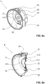
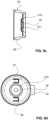
- the Figures 9a to 9d show the valve body 3.
- the valve body 3 is made of a flexible material, preferably silicone. It is preferably formed in one piece. It has a hollow cylindrical base body 30 with a rear wall 31.
- a through opening 32 is located centrally in the rear wall.
- the rear wall 31 has a ring-shaped groove 312 on the side facing away from the chest, which groove forms a sealing surface 310 on the opposite side, near the chest.
- the peripheral edge of the through opening 32 is provided with a peripheral sealing lip 311 on the side facing away from the chest (see Figures 9b and 9c ).
- the area of the rear wall 31 within the circumferential sealing surface 310 thus forms a valve which, as explained below, serves as a basic vacuum valve.
- the base body 30 has a radially protruding positioning lug 33 on the side facing the chest.
- a first nub 34 and a ventilation nub 35 are present on the casing of the base body 3.
- a second nub 36 is located diametrically opposite. The three nubs protrude radially outwards.
- the first nub 34 and the second nub 36 are solid, i.e. not hollow.
- the ventilation nub 35 has a through-opening from the interior of the base body 30 to the outside.
- valve flaps In the ring area of the rear wall 31 between the sealing surface 310 and the casing of the base body 30, there are also diametrically opposed valve flaps.
- a first of these valve flaps is provided with the reference number 37, a second of these valve flaps with the reference number 38. They are preferably located on the same diagonal as the first and second knobs 34, 36.
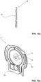
- the Figures 10a and 10b show the adjusting ring 5. It is preferably stiff and preferably made of plastic.
- the adjusting ring 5 preferably consists of two parts.
- a first part 50 has the shape of a half ring and is provided with a first plug part 51 at both free ends.
- the second part 52 also has the shape of a half ring and is provided with a second plug part 53 at each of its free ends.
- the first and two parts 50, 52 form a common ring and the two plug part pairs 51, 53 are provided with locking elements 54 in order to connect to one another preferably in a non-detachable manner.
- a first and a second pressure element 56, 57 are formed on the inner wall of the adjusting ring. These are preferably radially inwardly projecting elevations which merge via an inclined surface, also called a ramp, into a surface running parallel to the inner surface of the ring.
- An outwardly projecting actuating lever 58 is formed on the first part 50.
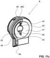
- the Figures 11a to 11c show the adapter part 4. It is preferably made of a rigid material, preferably plastic. It has a hollow cylindrical base body 40 with a substantially closed, flange-like pump-side wall 41.
- the base body 40 has a first window 400 and a diametrically opposite second window 401 in its casing.
- the pump-side wall 40 extends in a direction which is referred to here as below into a channel wall 410.
- the pump-side wall also has a raised central wall part 42 which projects into the area near the breast shield.
- a concave surface is thus formed which forms the already mentioned rigid first shell and is part of the pump chamber 47.
- a first through-opening 43 and a second through-opening 44 are present on the pump-side wall 41.
- the two through-openings 43, 44 are diametrically opposite one another. In this example, they are circular.
- a first backwash opening 45 and a second backwash opening 46 are preferably elongated. These openings all lead into the pump chamber 47.
- the concave, rigid first shell of the pump chamber 47 is surrounded by a circumferential, flat edge, which serves as a sealing surface.
- a channel 48 runs in this edge, which preferably begins at an uppermost point of the pump chamber 47 and is in fluid communication with it via an outlet opening 480.
- the channel 48 runs along the circumference of the pump chamber 47, here in a partially circular shape, downwards to an outlet 49.
- the outlet 49 is located in the channel wall 410.
- the media separation membrane 6 is shown. It is flexible, is preferably in one piece and is preferably made of silicone. It has a membrane surface 60, which is preferably provided in a known manner with at least one annular groove. A central region 61 of the membrane surface is preferably raised and faces the adapter part 4. The edge of the membrane surface 60 is designed as a sealing surface 62 and lies sealingly against the edge of the adapter part 4, whereby the pump chamber 47 is formed. A groove 63 runs within the sealing surface 62 along the circumference of the media separation membrane 6 and forms the sealing closure of the groove 48 of the adapter part 4. A recess 64 in the lower region of the media separation membrane 6 facing the pump housing serves as a free space for a pressure sensor, which is described below.
- the media separation membrane 6 preferably has, as shown in the figures, stiffeners in the form of ribs, which ensure the functioning of the media separation membrane. This means that the ribs ensure that the membrane moves in the desired manner and nevertheless always lies tightly against its adjacent parts.
- the pump membrane 7 is shown. It also has a membrane surface 70 and a central area 71. In contrast to the full-surface media separation membrane 6, the central area 71 of the pump membrane 7 is provided with a through-opening 72, the edge area of which preferably has a reinforcement 73, here in the form of ribs. There is again a circumferential sealing surface 74 which, when the device is assembled, seals against the corresponding surface of the carrier module 8'. Outside the sealing surface 74 there are side wings 77. The side wings 77 form together with the circumferential flat sealing surface 74 ( Figure 13b ) when assembled, form a tight barrier against external liquids and thus protect the electronics.
- the lower area of the pump membrane 7, which is still located within the closed circumferential sealing surface 74, is designed as a pressure sensor.
- the pressure sensor comprises a sensor surface 75 in the form of a membrane, which is connected to the membrane surface 70 via a connecting web, and a flag 76, which protrudes perpendicularly from the sensor surface in the direction of the pump housing. This type of pressure sensor is in WO 2013/049944 A1 described.
- the media separation membrane 6 and the pump membrane 7 have similar shapes, in particular with regard to their regions that can be moved to generate the negative pressure.
- the carrier module includes
- the carrier module 8' is in Figure 14 It is held in an outer casing of the pump housing.
- the outer casing is in Figure 1 visible.
- the carrier module 8' is screwed into this outer housing.
- the corresponding fastening holes are provided with the reference number 84.
- the carrier module can be made in one piece from plastic. However, it can also be made in several parts and/or from another material.
- the carrier module 8' has two protruding side arms 10 with a bayonet lock for holding the breast shield 2.
- the side arms are arranged laterally on a spindle holder 82.
- the spindle holder 82 has a Through-opening and a peripheral edge 85, which forms the counterpart to the sealing surface 74 of the pump membrane 7.
- a motor holder 81 in the form of a shell is formed on the spindle holder 82.
- the motor holder 81 serves to hold an electric motor, which is connected to a spindle 83 (see Figure 4 ) is connected.
- the valve body 3 can be inserted into the hollow cylindrical base body 40 of the adapter part 4 in a rotationally positioned manner.
- the adjusting ring 5 is already permanently connected to the adapter part 4, with the first pressing element 56 protruding inwards through the first window 400 and the second pressing element 57 protruding inwards through the second window 401.
- the first knob 34 of the valve body 3 is located below the first window 400 and the second knob 36 above the first window 401.
- the valve flaps 37, 38 of the valve body 3 are each located above the first and second through-openings 43, 44 of the adapter part.
- the sealing lip 311 rests sealingly on the raised wall part 42, with the first and second backwash openings being arranged in a sealed ring area between the groove 312 and the sealing lip 311.
- the first knob 34 is located over the first outlet opening 24 and the ventilation knob 35 is located over the first ventilation opening 26.
- the second knob 36 is located over the second outlet opening 27.
- the second ventilation opening 29 is covered by the casing of the valve body 4 and is thus closed.
- the spindle 83 can be seen, which drives the pump membrane 7.
- the media separation membrane 6 has a shape which fits snugly against the pump membrane 7, so that both membranes 6, 7 move together and no losses occur here either.
- the pump housing 8, more precisely the carrier module 8' has a rear wall 85, against which the pump membrane 7 rests in a sealing manner when the hygiene module is attached to the carrier module 8'. This is shown in the Figures 4 and 5 clearly visible.
- the adjusting ring 5 is arranged so that it can pivot within the side arms 80, whereby the actuating lever 58 also serves as a display element. It moves along a display 87 which is attached to the pump housing 8 and which thus provides the user with information about the position of individual valves and thus the operating status of the pump. This means that it shows whether the pump is ready for pumping or is in the emptying state. This is explained below.
- the first ventilation opening 26 is opened and closed together with the second outlet opening 27 and the second flow opening 28.
- the second ventilation opening 29 always remains closed due to its position within the valve body 3.
- the breast shield 2 is positioned relative to the valve body 3 such that the second openings are at the position of the first openings, the second ventilation opening will of course be opened and closed instead of the first.
- the second knob 36 of the valve body 3 is pressed downwards by the second pressing element 57 of the adjusting ring and rests on the recess and thus the second outlet opening 27 and the second flow opening 28 of the breast shield 2.
- the ventilation knob 35 is pressed by the first pressing element 56 onto the first ventilation opening 26 and closes it.
- the first knob 34 of the valve body 3 is released so that the first outlet opening 24 and the first Flow opening 25 forms a fluid-communicating channel from the interior 200 of the breast shield into the base body 30 of the valve body 3. This is best done in the Figures 2 , 3 and 6 recognizable.
- the adjusting ring 5 In a second position, the adjusting ring 5 is rotated.
- the first pressing element 56 releases the ventilation knob 35 and thus the first ventilation opening 26, but presses the first knob 34 onto the recess and thus closes the first outlet opening 24 and the first flow opening 25.
- the second pressing element 57 also releases the second knob 36, so that the second outlet opening 27 and the second flow opening 28 now form an open, continuous channel from the interior 200 of the breast shield 2 into the valve body 3.
- the second outlet opening 27 and the second flow opening 28 form an emptying channel, which is described in more detail below.
- the mutual opening and closing preferably takes place simultaneously.
- the actuating lever 58 and thus the adjusting ring 5 are brought into the first position mentioned.
- the pump membrane 7 is moved together with the media separation membrane 6 back and forth to the adapter part 4, so that a negative pressure is created in the pump chamber 47 and in the interior 200 of the breast shield 2.
- the vacuum line from the pump chamber 47 into the interior 200 of the breast shield 2 is formed by the first through-opening 43 in the adapter part 4, the opening in the valve body 3 covered by the first valve flap 37 and the channel formed by the first flow opening 25 and the first outlet opening 24 in the breast shield.
- the basic vacuum valve formed among other things by the sealing lip 311 of the valve body 3, enables a basic negative pressure to be maintained in the interior 200 of the breast shield 2 when the pump stroke is directed towards atmospheric pressure.
- the basic vacuum valve opens during the pump stroke towards atmospheric pressure and only closes when a predetermined minimum pressure is reached in the interior 200. The mode of operation is explained in more detail below using a diagram.
- the air flows back into the breast shield 2 via the first and second backwash openings 45, 46 of the adapter part 4, the through opening 32 of the valve body 3 and the through opening 21 of the breast shield 2.
- the breast shield 2 is preferably held such that this first outlet opening 24 is located in an upper region of the breast shield 2.
- the pumped milk then flows through the channel formed by the first outlet opening 24 and the first passage opening 25, and through the opening covered by the first valve flap 37 into the adapter part 4, where it passes through the first passage opening 43 into the pump chamber 47.
- the pump chamber 47 also fills with milk until the outlet opening 480 arranged at the top is reached.
- the milk then flows through the channel formed by the groove 48 of the adapter part 4 and the groove 63 or the cover of the media separation membrane 6 through the outlet 49 out of the hygiene module and through the container valve 94 into the milk collection container 9.
- the base vacuum valve opens first and allows a partial backflow of the air or milk into the interior 200. This partial backflow occurs through the first and second backwash openings 45, 46, the open base vacuum valve, the through opening 32 and the through opening 21.
- the valve closes at a certain vacuum value in the interior so that the pressure cannot rise further towards atmospheric pressure.
- the milk that has already been pumped out of the mother's breast and is still in the interior 200 of the breast shield 2 is pumped through the second release opening 27, the second passage opening 28, the opening in the valve body 3 covered by the second valve flap 37 and the second passage opening 44 in the adapter part 4 into the pump chamber 47. From there it is displaced from the pump chamber 47 in the direction of the outlet opening 480 by the movement of the pump membrane 7 and the media separation membrane 6. It therefore also flows through the channel 48 and the outlet 49 into the milk collection container 9. In this way, both the interior 200 of the breast shield 2 and the pump chamber 47 can be almost completely emptied.
- the device can also be placed in an inclined position in order to empty all the milk from the system into the milk collection container 9.
- the breast pump is preferably held in such a way that the first outlet opening 24 of the breast shield and the outlet opening 480 of the pumping chamber 47 are located in an upper area of the respective hollow space.
- This allows air to escape from the system and the two hollow chambers are filled with milk relatively quickly.
- This enables the system to switch as quickly as possible from a purely pneumatic pumping system with air as the working fluid to a purely or predominantly hydraulic pumping system in which milk forms the working fluid or at least forms a large proportion of the working fluid.
- the breast pump can be placed in any position. This applies not only to the breast shield 2 and the pump chamber 47, but in particular also for the milk collection container 9. Thanks to the container valve 94 designed as a non-return valve and thanks to the liquid-tight cover 92, the milk collection container 9 can even be turned upside down without affecting the operation of the breast pump.
- the breast shield and the adjusting ring are illuminated so that the mother can carry out a visual check even at night while pumping.
- the breast shield 2 is shown schematically with the interior 200.
- the breast shield 2 is placed sealingly on a mother's breast, the nipple W protrudes into the interior 200.
- the interior 200 is connected to a pump chamber 47 via an outlet opening 16.
- An additional emptying opening 19 also leads from the interior 200 to the pump chamber 47.
- the outlet opening 16 is provided with a pump valve 12, the emptying opening with an emptying valve 14.
- a basic vacuum valve 13 closes a third opening 17 between the pump chamber 47 and the interior 200 of the breast shield 2.
- the volume of the pump chamber 47 can be changed by means of a pumping means 10, for example a pumping membrane or a piston.
- the pumping means 10 is driven, for example by means of a spindle 100.
- An outlet opening 480 leads from the pump chamber 47 into a milk collecting container 9.
- the inlet into the milk collecting container 9 is preferably provided with a check valve, here called container valve 94.
- the milk collecting container 9 is ventilated, Preferably, an inlet 95 with an inlet valve 96 is provided for this purpose.
- the outlet opening 16 and the base vacuum valve 12 of the schematic representation correspond to the first outlet opening 24, the first flow opening 25, the first nub 34, the first pressure element 56 and the first valve flap 37 of the concrete embodiment.
- the drain opening 19 and the drain valve 14 of the schematic representation correspond to the second outlet opening 27, the second flow opening 28, the second knob 36, the second pressure element 57 and the second valve flap 38 of the concrete embodiment.
- the base vacuum valve 13 and the third opening 17 of the schematic representation correspond to the sealing lip 311, the first and second backwash openings 45, 46 and the through opening 32 in the valve body 3 of the concrete embodiment.
- the container valve 94 of the schematic representation corresponds to the container valve of the concrete embodiment.
- the inlet 95 and the inlet valve 96 of the schematic representation are formed by the air-permeable and liquid-impermeable cover, i.e. by an appropriately selected cover film.
- valves can also be implemented in other ways.
- the valve openings can also be accommodated in an additional module part which is detachably connected to the breast shield.
- the outlet opening 16 and/or the emptying opening 19 can be designed as a channel which runs in a line, in particular a flexible line.
- the The pump chamber can be arranged at a distance from the breast shield and, depending on the design, also at a distance from a valve module.
- the valves can preferably be accommodated in a hygiene module which is arranged between the pump chamber and the breast shield funnel. If the pump chamber is arranged at a distance from the breast shield, the valve module can be arranged adjacent to the pump chamber or adjacent to the breast shield or can be a component of the breast shield.
- the pumping process begins and the mother's breast is stimulated by the applied negative pressure.
- the pump valve 12 can open and close.
- the first outlet opening 24 and the first flow opening 25 are exposed for this purpose and the first valve flap 37 opens and closes the valve.
- the drain valve 14 is firmly closed. In the specific embodiment, this is done by the adjusting ring 5 being brought into the appropriate position and the second outlet opening 27 and the second flow opening 28 being firmly closed.
- the ventilation valve 11 also remains firmly closed. In the specific embodiment, this is achieved by the first knob 34 closing the first ventilation opening 26 by means of the adjusting ring 5.
- the pumping means 10 preferably a pumping membrane or a piston, is pulled outwards to create a negative pressure in the pumping chamber 47 (here, for example, -150 mmHg).
- the pumping valve 12 opens and the negative pressure is transferred to the interior 200 of the breast shield 2, or air flows from this interior into the pumping chamber 47.
- a negative pressure also prevails in the interior, ideally the same pressure of, for example, -150 mmHg.
- the pressure curve in the interior 200 is in Figure 19c
- the pressure according to reference symbol a) corresponds to the pressure in the interior 200 according to Figure 19a .
- the container valve 94 remains closed.
- FIGs 20a to 20c the flow of milk from the mother's breast has begun.
- the milk is marked with the reference symbol M in the figures.
- the interior 200 of the breast shield 2 fills with pumped milk.
- a lake of milk is created below the pump valve 12. Thanks to the milk now available, the pumping power increases with the drive power remaining the same, for example to -170 mmHg in the pump chamber 47 and the interior 200.
- the pump valve 12 and the basic vacuum valve 13 open and close with each pump stroke, while the emptying valve 14 and the ventilation valve 11 remain closed.
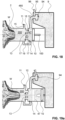
- Figure 20a shows the situation at maximum negative pressure (absolute value), which is also indicated with a) in Figure 20c is marked.
- Figure 20b shows the situation when maintaining the base negative pressure in the interior 200 and atmospheric pressure in the pump chamber 47, which in Figure 20c marked with b).
- milk M flows through the pump valve 12 into the pump chamber 47.
- the pumped milk M now also fills the pump chamber 47 until its fill level reaches the outlet opening 480 to the milk collection container 9.
- the container valve 94 now opens, preferably due to the pressure of the accumulated milk M, and milk M flows into the milk collection container 9.
- FIGS. 21a to 21c show the situation in which there is optimally no air left in the system and the original pneumatic system is completely switched to a hydraulic system.
- a mixed system is often present, with the pumped milk preferably filling a significant part of the volumes and thus forming the main working fluid.
- the pump valve 12 and the base vacuum valve 13 open and close according to the pump stroke, so that a negative pressure is generated in the interior 200 and a base negative pressure can be maintained.
- the pressure in the pump chamber 47 changes, for example, between -250 mmHg and 0 mmHg, the pressure in the interior between -250 mmHg and -20 mmHg.
- the pressure in the milk collection container 9 remains at atmospheric pressure, i.e. at 0 mmHg.
- the pump valve 12 is now firmly closed and the emptying channel and the emptying valve 14 are opened.
- the pump means 10 continues to move and generates a pressure in the pump chamber 47 that changes from a maximum negative pressure to atmospheric pressure.
- the emptying valve 14 opens and closes, as did the pump valve 12 before, and thus pumps the milk M from the interior 200 into the pump chamber 47. From there it is conveyed into the milk collection container 9, preferably first by means of negative pressure and then by displacement by the pump means 10.
- the emptying valve 14 is preferably located at a low point on the breast shield, preferably relatively far down.
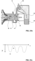
- the sinking lake of milk in the interior is in the Figures 23a and 23b clearly visible.
- the Figures 23a and 23b show the two extreme situations of a pumping stroke.
- the pressure curve is in Figure 23c
- the pressure curve in the interior 200 is relatively unspecific.
- the pump is therefore still activated during emptying. If there is still milk in the pump chamber 47 at the end, it can be easily directed into the milk collection container 9 by tilting or "turning upside down” the pump.
- the breast pump according to the invention thus enables the use of pumped milk in a hydraulic pumping system, which can minimize the drive of the pump.
- REFERENCE SYMBOL LIST 32 passage opening 10 pumping agent 33 positioning mass 100 spindle 34 first pimple 11 ventilation valve 35 ventilation nub 12 pump valve 36 second pimple 13 base vacuum valve 37 first valve flap 14 drain valve 38 second valve flap 15 ventilation opening 16 outlet opening 4 adapter part 17 third opening 40 base body 19 drain opening 400 first window 401 second window 2 breast shield 402 positioning aid 20 funnel 41 pump-side wall 200 interior 410 canal wall 21 passage opening 42 raised wall section 22 flange 43 first passage opening 23 Support 44 second passage opening 24 first outlet opening 45 first backwash opening 25 first flow opening 46 second backwash opening 26 first ventilation opening 47 pump chamber 27 second outlet opening 48 gutter 28 second flow opening 480 outlet opening 29 second ventilation opening 49 outlet 3 valve body 5 adjusting ring 30 base body 50 first part 31 back wall 51 first connector part 310 sealing surface 52 second part 311 sealing lip 53 second connector part 312 groove 54 locking element 55 stop 83 spindle 56 first
Landscapes
- Health & Medical Sciences (AREA)
- Heart & Thoracic Surgery (AREA)
- Life Sciences & Earth Sciences (AREA)
- Animal Behavior & Ethology (AREA)
- Engineering & Computer Science (AREA)
- Anesthesiology (AREA)
- Biomedical Technology (AREA)
- Hematology (AREA)
- Veterinary Medicine (AREA)
- Public Health (AREA)
- General Health & Medical Sciences (AREA)
- Vascular Medicine (AREA)
- Pediatric Medicine (AREA)
- Pulmonology (AREA)
- External Artificial Organs (AREA)
- Medical Preparation Storing Or Oral Administration Devices (AREA)
- Prostheses (AREA)
Claims (30)
- Tire-lait pour extraire le lait maternel humain, le tire-lait présentant un boîtier de pompe (8) avec une unité d'entraînement, une chambre de pompage (47) avec une membrane de pompage (7) flexible pouvant être entraînée par l'unité d'entraînement pour produire un vide et une téterelle (2) avec un espace intérieur (200) pour recevoir un sein maternel,l'espace intérieur (200) pouvant être alimenté au moyen de la chambre de pompage (47) avec une dépression variant de manière cyclique,dans lequel un canal à lait mène de l'espace intérieur (200) vers la chambre de pompage (47) à travers une première ouverture d'entrée en tant que première ouverture de passage (43), dans lequel du lait tiré (M) s'écoule de l'espace intérieur (200) de la téterelle (2) à travers le canal à lait dans la chambre de pompage (47), et dans lequel la chambre de pompage (47) présente une ouverture de sortie (480),à travers laquelle le lait tiré (M) s'écoule de la chambre de pompage (47) dans un récipient de collecte de lait (9),un module d'hygiène en plusieurs parties étant présent, le module d'hygiène présentant une première partie (23) avec une ouverture d'écoulement (25, 28) pour la liaison avec l'espace intérieur (200), un corps de valve (3) avec au moins une valve et une deuxième partie en tant que partie d'adaptation (4) avec une première coque rigide pour former la chambre de pompage (47), le corps de valve (3) étant disposé entre la première et la deuxième partie, le module d'hygiène en tant qu'ensemble pouvant être relié de manière étanche et détachable au boîtier de pompe (8) du tire-lait,caractérisé en ceque la téterelle(2) présente une bride (22) pour la liaison amovible avec le boîtier de pompe (8).
- Tire-lait selon la revendication 1, dans lequel la première coque rigide comprend un trajet de lait qui mène de la chambre de pompage (47) à un récipient de collecte de lait (9) et qui s'étend au moins sur une zone partielle perpendiculairement à un axe d'entraînement de la membrane de pompage (7).
- Tire-lait selon l'une des revendications 1 ou 2, dans lequel le corps de valve (3) comprend au moins une valve de débit et une valve d'aération (11).
- Tire-lait selon l'une des revendications 1 à 3, dans lequel le corps de valve (3) est formé d'une seule pièce en un matériau flexible.
- Tire-lait selon l'une des revendications 1 à 4, dans lequel la première partie (23) fait partie intégrante de la téterelle (2).
- Tire-lait selon l'une quelconque des revendications 1 à 5, dans lequel l'assemblage est réalisé par complémentarité de formes et de forces.
- Tire-lait selon la revendication 6, dans lequel le raccord est un raccord à baïonnette.
- Tire-lait selon la revendication 1, dans lequel l'ouverture de sortie (480) est disposée, en position d'utilisation verticale du tire-lait, au moins au début d'un processus d'extraction de lait, dans une zone supérieure de la chambre de pompage (47) et/ou au-dessus de la première ouverture de passage (43).
- Tire-lait selon la revendication 1, dans lequel le canal à lait forme un canal à vide pour alimenter l'espace intérieur (200) de la téterelle (2) avec la dépression qui varie de manière cyclique.
- Tire-lait selon l'une des revendications 8 ou 9, dans lequel la chambre de pompage (47) comprend la première coque rigide et la membrane de pompage flexible (7), dans lequel la membrane de pompage (7) s'applique de manière étanche contre la première coque rigide et dans lequel la membrane de pompage (7) peut être entraînée au moyen de l'unité d'entraînement et une dépression peut être produite dans la chambre de pompage (47) par son déplacement par rapport à la première coque rigide.
- Tire-lait selon la revendication 10, dans lequel une membrane de séparation de milieu flexible (6) est disposée entre la première coque rigide et la membrane de pompage flexible (7), de sorte que la membrane de pompage (7) est protégée d'un contact avec le lait tiré (M).
- Tire-lait selon l'une des revendications 10 ou 11, dans lequel la première coque rigide comprend une goulotte de sortie (48) s'étendant depuis l'orifice de sortie (480) de la chambre de pompage (47) jusqu'à une sortie (49), la goulotte de sortie s'étendant sur au moins une partie de celle-ci dans une direction perpendiculaire à la direction de déplacement de la membrane de pompage (7) .
- Tire-lait selon la revendication 12, dans lequel la membrane de pompage (7), ou, si elle est présente, la membrane de séparation des fluides (6), ferme la goulotte de sortie (48) de la première coque rigide pour former un canal fermé à l'exception de l'ouverture de sortie (480) et de la sortie (49).
- Tire-lait selon l'une des revendications 1 à 13, dans lequel la téterelle (2) présente l'ouverture d'écoulement (25) comme première ouverture d'écoulement (25), qui forme une partie du canal à lait, la première ouverture d'écoulement (25) étant disposée, en position d'utilisation de la téterelle (2), au moins au début du processus d'extraction, dans une zone supérieure de l'espace intérieur (200), de sorte que l'espace intérieur (200) peut être rempli de lait tiré (M) en dessous de la première ouverture d'écoulement (25).
- Tire-lait selon l'une quelconque des revendications 1 à 14, dans lequel le canal à lait peut être fermé au moyen d'une première valve afin d'évacuer le lait tiré (M) de la chambre de pompage (47) à la fin de l'opération de tirage.
- Tire-lait selon l'une quelconque des revendications 1 à 15, dans lequel un canal d'évacuation est présent entre l'espace intérieur (200) de la téterelle (2) et la chambre de pompage (47), lequel s'étend séparément du canal à lait, et dans lequel le canal d'évacuation peut être fermé au moyen d'une deuxième valve, le canal d'évacuation étant fermé pendant l'opération de tirage et ouvert à la fin de l'opération de tirage.
- Tire-lait selon l'une quelconque des revendications 1 à 16, dans lequel une ou la valve d'aération (11) est présente pour aérer l'intérieur (200) de la téterelle (2).
- Tire-lait selon les revendications 16 et 17, dans lequel la valve d'aération (11) peut être fermée conjointement à la deuxième valve et peut être ouverte conjointement à celle-ci.
- Tire-lait selon l'une quelconque des revendications 1 à 18, dans lequel il existe une troisième valve qui maintient une dépression de base dans l'espace intérieur (200) de la téterelle (2) en cas d'augmentation de pression de la dépression qui varie de manière cyclique.
- Tire-lait selon l'une quelconque des revendications 1 à 19, dans lequel une quatrième valve est présente dans le canal à lait, qui s'ouvre et se ferme en fonction de la dépression appliquée.
- Tire-lait selon l'une quelconque des revendications 1 à 20 et la revendication 16, dans lequel une cinquième valve est présente dans le canal d'évacuation, laquelle s'ouvre et se ferme en fonction de la dépression appliquée.
- Tire-lait selon l'une quelconque des revendications 1 à 21, dans lequel au moins une partie, de préférence la totalité, desdites valves sont disposées dans le corps de valve (3).
- Tire-lait selon la revendication 22, dans lequel le corps de valve (3) est formé d'une seule pièce et est flexible.
- Tire-lait selon l'une quelconque des revendications 10 à 23, si l'on se réfère à la revendication 10, dans lequel le tire-lait comprend le boîtier de pompe (8) avec l'unité d'entraînement pour la membrane de pompage (7) et dans lequel la première coque rigide est reliée de manière amovible au boîtier de pompe (8) .
- Tire-lait selon la revendication 24, dans lequel la première coque rigide fait partie du module d'hygiène, qui peut être relié conjointement au boîtier de pompe (8), le module d'hygiène présentant en outre au moins les valves mentionnées.
- Tire-lait selon les revendications 23 et 25, dans lequel la première coque rigide fait partie de la pièce d'adaptation (4) et dans lequel le corps de valve (3) est maintenu dans un logement de la pièce d'adaptation (4).
- Tire-lait selon la revendication 26, dans lequel le module d'hygiène comprend en outre un moyen d'actionnement manuel pour actionner simultanément la première et la deuxième valve.
- Tire-lait selon la revendication 27, dans lequel la pièce d'adaptation (4) et le moyen d'actionnement ne peuvent pas être détachés l'un de l'autre sans être détruits.
- Tire-lait selon l'une des revendications 1 à 28, dans lequel le tire-lait présente le boîtier de pompe (8), dans lequel la téterelle (2) peut être fixée de manière amovible au boîtier de pompe (8) et dans lequel, par la fixation de la téterelle (2) au boîtier de pompe (8), des parties qui se trouvent entre la téterelle (2) et le boîtier de pompe (8) sont reliées entre elles de manière étanche, de sorte qu'il se forme une liaison étanche entre la chambre de pompage (47) et l'espace intérieur (200) de la téterelle (2).
- Tire-lait selon les revendications 25 et 29, dans lequel la téterelle (2) et le corps de valve (3) font partie du module d'hygiène.
Priority Applications (1)
| Application Number | Priority Date | Filing Date | Title |
|---|---|---|---|
| EP24158388.9A EP4344712A3 (fr) | 2017-10-24 | 2017-10-24 | Pompe tire-lait |
Applications Claiming Priority (1)
| Application Number | Priority Date | Filing Date | Title |
|---|---|---|---|
| PCT/EP2017/077141 WO2019080995A1 (fr) | 2017-10-24 | 2017-10-24 | Pompe tire-lait |
Related Child Applications (2)
| Application Number | Title | Priority Date | Filing Date |
|---|---|---|---|
| EP24158388.9A Division EP4344712A3 (fr) | 2017-10-24 | 2017-10-24 | Pompe tire-lait |
| EP24158388.9A Division-Into EP4344712A3 (fr) | 2017-10-24 | 2017-10-24 | Pompe tire-lait |
Publications (2)
| Publication Number | Publication Date |
|---|---|
| EP3700603A1 EP3700603A1 (fr) | 2020-09-02 |
| EP3700603B1 true EP3700603B1 (fr) | 2024-12-04 |
Family
ID=60153330
Family Applications (2)
| Application Number | Title | Priority Date | Filing Date |
|---|---|---|---|
| EP24158388.9A Pending EP4344712A3 (fr) | 2017-10-24 | 2017-10-24 | Pompe tire-lait |
| EP17787438.5A Active EP3700603B1 (fr) | 2017-10-24 | 2017-10-24 | Pompe tire-lait |
Family Applications Before (1)
| Application Number | Title | Priority Date | Filing Date |
|---|---|---|---|
| EP24158388.9A Pending EP4344712A3 (fr) | 2017-10-24 | 2017-10-24 | Pompe tire-lait |
Country Status (12)
| Country | Link |
|---|---|
| US (2) | US11904077B2 (fr) |
| EP (2) | EP4344712A3 (fr) |
| JP (2) | JP7029530B2 (fr) |
| KR (1) | KR102516565B1 (fr) |
| CN (2) | CN115804879A (fr) |
| AU (2) | AU2017437176B2 (fr) |
| BR (1) | BR112020007991A2 (fr) |
| CA (1) | CA3080259A1 (fr) |
| IL (1) | IL273944B2 (fr) |
| RU (1) | RU2754384C1 (fr) |
| TW (1) | TWI798273B (fr) |
| WO (1) | WO2019080995A1 (fr) |
Families Citing this family (29)
| Publication number | Priority date | Publication date | Assignee | Title |
|---|---|---|---|---|
| DE202018006777U1 (de) | 2017-06-15 | 2022-12-14 | Chiaro Technology Limited | Brustpumpensystem |
| KR102516565B1 (ko) * | 2017-10-24 | 2023-03-30 | 메델라 홀딩 아게 | 착유기 |
| KR20210011992A (ko) * | 2018-05-21 | 2021-02-02 | 윌로우 이노베이션즈, 인크. | 유축기용 용기 어셈블리 |
| WO2021165892A1 (fr) * | 2020-02-21 | 2021-08-26 | Medela Holding Ag | Ensemble tire-lait et procédé de fonctionnement |
| GB202004395D0 (en) | 2020-03-26 | 2020-05-13 | Chiaro Technology Ltd | Lima |
| CN111701098B (zh) * | 2020-07-08 | 2024-08-06 | 方国峰 | 奶碗及其吸奶器 |
| EP4015010A1 (fr) * | 2020-12-16 | 2022-06-22 | Koninklijke Philips N.V. | Système de tire-lait |
| CN217548652U (zh) * | 2020-12-16 | 2022-10-11 | 皇家飞利浦有限公司 | 吸乳泵 |
| CN112717219B (zh) * | 2020-12-24 | 2024-01-23 | 大悦创新(苏州)医疗科技股份有限公司 | 负压泵组件和负压吸乳装置 |
| US11779688B2 (en) * | 2021-01-21 | 2023-10-10 | Wayne D Turner | Breast shield |
| EP4059535A1 (fr) * | 2021-03-16 | 2022-09-21 | Koninklijke Philips N.V. | Tire-lait ou ensemble de collecte de lait |
| TW202243696A (zh) * | 2021-05-10 | 2022-11-16 | 瑞士商美德拉控股股份有限公司 | 乳房泵 |
| EP4112092B1 (fr) * | 2021-06-24 | 2024-03-13 | Medela Holding AG | Tire-lait |
| EP4197567A1 (fr) * | 2021-12-20 | 2023-06-21 | Koninklijke Philips N.V. | Tire-lait |
| EP4452354B1 (fr) | 2021-12-20 | 2025-09-03 | Koninklijke Philips N.V. | Tire-lait |
| JP2025514045A (ja) * | 2022-04-28 | 2025-05-02 | ケアフュージョン 303、インコーポレイテッド | 注入ラインからガスを除去するための装置及び方法 |
| GB2620364A (en) * | 2022-06-20 | 2024-01-10 | Mayborn Uk Ltd | Breast pump and breast pump valve assembly |
| US12521472B2 (en) * | 2022-08-17 | 2026-01-13 | Wayne D. Turner | Breast shield with suckling motion one way valve |
| GB2622570B (en) | 2022-08-31 | 2024-12-11 | Chiaro Technology Ltd | Breast pump |
| GB2622196A (en) | 2022-08-31 | 2024-03-13 | Chiaro Technology Ltd | Measurement system |
| USD1034953S1 (en) * | 2022-09-15 | 2024-07-09 | JinZhong Yan | Breast pump part |
| EP4454676A1 (fr) | 2023-04-28 | 2024-10-30 | Medela Holding AG | Tire-lait |
| EP4454675A1 (fr) | 2023-04-28 | 2024-10-30 | Medela Holding AG | Tire-lait |
| EP4454674A1 (fr) | 2023-04-28 | 2024-10-30 | Medela Holding AG | Tire-lait |
| CN117323479A (zh) * | 2023-11-13 | 2024-01-02 | 东莞市嵘懋医疗科技有限公司 | 吸奶器 |
| WO2025102975A1 (fr) * | 2023-11-14 | 2025-05-22 | 宁波小悟品牌管理有限公司 | Appareil de tirage de lait à aspiration automatique et tire-lait |
| WO2025199804A1 (fr) * | 2024-03-27 | 2025-10-02 | 深圳市路特佳成供应链管理有限公司 | Tire-lait |
| WO2025214256A1 (fr) * | 2024-04-07 | 2025-10-16 | 深圳市路特佳成供应链管理有限公司 | Tire-lait |
| CN120132099A (zh) * | 2025-03-13 | 2025-06-13 | 深圳市森姆泵业科技有限公司 | 一种驱动装置及用于运行该驱动装置的方法 |
Citations (2)
| Publication number | Priority date | Publication date | Assignee | Title |
|---|---|---|---|---|
| WO2016014494A1 (fr) * | 2014-07-22 | 2016-01-28 | Exploramed Nc7, Llc | Système de pompe tire-lait et procédés associés |
| WO2016014469A1 (fr) * | 2014-07-22 | 2016-01-28 | Exploramed Nc7, Llc | Système de tire-lait et procédés |
Family Cites Families (27)
| Publication number | Priority date | Publication date | Assignee | Title |
|---|---|---|---|---|
| US7066918B2 (en) * | 2001-10-15 | 2006-06-27 | Charles Herbert N | Closed coupled urine collection chamber |
| US6749582B2 (en) * | 2002-04-30 | 2004-06-15 | The First Years Inc. | Pumping breast milk |
| US8152754B2 (en) | 2004-04-01 | 2012-04-10 | Medela Holding Ag | Soft breastshield |
| DE102004030692B3 (de) | 2004-06-24 | 2005-12-22 | Kaweco Gmbh | Milchabsaugvorrichtung |
| WO2007017968A1 (fr) * | 2005-08-09 | 2007-02-15 | Pigeon Corporation | Dispositif de traite |
| US8187227B2 (en) * | 2006-11-01 | 2012-05-29 | Medela Holding Ag | Self returning contamination barrier |
| US8070715B2 (en) * | 2007-04-11 | 2011-12-06 | Medela Holding Ag | Method and apparatus for minimum negative pressure control, particularly for breastpump with breastshield pressure control system |
| JP5204533B2 (ja) | 2008-04-04 | 2013-06-05 | ピジョン株式会社 | 搾乳器 |
| CN102271726B (zh) * | 2008-11-07 | 2014-10-08 | 辛普里斯公司 | 吸奶器 |
| PL2480265T3 (pl) | 2009-09-22 | 2015-11-30 | Medela Holding Ag | Kapturek laktacyjny do odciągania pokarmu kobiecego |
| DE102010019041A1 (de) * | 2010-05-03 | 2011-11-03 | Mapa Gmbh | Elektrische Muttermilchpumpe |
| CH703813A1 (de) | 2010-09-17 | 2012-03-30 | Medela Holding Ag | Membranvakuumpumpe. |
| SG11201400736UA (en) | 2011-10-04 | 2014-09-26 | Medela Holding Ag | Vacuum pump |
| CH707363A1 (de) * | 2012-12-18 | 2014-06-30 | Medela Holding Ag | Brusthaubeneinheit mit Medientrennung. |
| EP2968713B1 (fr) * | 2013-03-14 | 2019-10-02 | Medela Holding AG | Collecte de petit volume pour un système de tire-lait |
| US20160000980A1 (en) * | 2014-03-20 | 2016-01-07 | Naya Health, Inc. | Pump apparatus and methods for expression of human breast milk |
| RU2691003C2 (ru) * | 2014-06-05 | 2019-06-07 | Конинклейке Филипс Н.В. | Молокоотсос |
| WO2016014488A1 (fr) * | 2014-07-22 | 2016-01-28 | Exploramed Nc7, Llc | Procédés et système de tire-lait |
| WO2016014483A1 (fr) * | 2014-07-22 | 2016-01-28 | Exploramed Nc7, Llc | Système de tire-lait et procédés |
| US10434230B2 (en) * | 2015-02-20 | 2019-10-08 | Medela Holding Ag | Adapter with media separating diaphragm for a breast shield |
| EP3258983B1 (fr) * | 2015-02-20 | 2019-03-20 | Medela Holding AG | Tire-lait et couvercle correspondant |
| EP3058967A1 (fr) * | 2015-02-20 | 2016-08-24 | Medela Holding AG | unité de tire-lait et connecteur pour un tire-lait |
| KR102715129B1 (ko) * | 2016-02-10 | 2024-10-11 | 윌로우 이노베이션즈, 인크. | 유축 시스템 |
| CN108697834B (zh) | 2016-02-24 | 2022-01-14 | 皇家飞利浦有限公司 | 吸奶器及其操作方法 |
| CN108883213B (zh) | 2016-03-15 | 2022-04-08 | 皇家飞利浦有限公司 | 挤出套件 |
| US20180093024A1 (en) * | 2016-10-05 | 2018-04-05 | Moxxly, Inc. | Breast pump milk capture and collection system |
| KR102516565B1 (ko) * | 2017-10-24 | 2023-03-30 | 메델라 홀딩 아게 | 착유기 |
-
2017
- 2017-10-24 KR KR1020207013813A patent/KR102516565B1/ko active Active
- 2017-10-24 AU AU2017437176A patent/AU2017437176B2/en active Active
- 2017-10-24 CN CN202211260717.0A patent/CN115804879A/zh active Pending
- 2017-10-24 US US16/756,092 patent/US11904077B2/en active Active
- 2017-10-24 EP EP24158388.9A patent/EP4344712A3/fr active Pending
- 2017-10-24 CN CN201780096228.7A patent/CN111263648B/zh active Active
- 2017-10-24 EP EP17787438.5A patent/EP3700603B1/fr active Active
- 2017-10-24 BR BR112020007991-0A patent/BR112020007991A2/pt not_active IP Right Cessation
- 2017-10-24 JP JP2020522874A patent/JP7029530B2/ja active Active
- 2017-10-24 IL IL273944A patent/IL273944B2/en unknown
- 2017-10-24 WO PCT/EP2017/077141 patent/WO2019080995A1/fr not_active Ceased
- 2017-10-24 RU RU2020115691A patent/RU2754384C1/ru active
- 2017-10-24 CA CA3080259A patent/CA3080259A1/fr active Pending
-
2018
- 2018-10-17 TW TW107136555A patent/TWI798273B/zh active
-
2022
- 2022-02-18 JP JP2022023396A patent/JP2022068293A/ja active Pending
-
2024
- 2024-01-09 US US18/408,188 patent/US20240139388A1/en active Pending
- 2024-02-06 AU AU2024200706A patent/AU2024200706B2/en active Active
Patent Citations (2)
| Publication number | Priority date | Publication date | Assignee | Title |
|---|---|---|---|---|
| WO2016014494A1 (fr) * | 2014-07-22 | 2016-01-28 | Exploramed Nc7, Llc | Système de pompe tire-lait et procédés associés |
| WO2016014469A1 (fr) * | 2014-07-22 | 2016-01-28 | Exploramed Nc7, Llc | Système de tire-lait et procédés |
Also Published As
| Publication number | Publication date |
|---|---|
| US11904077B2 (en) | 2024-02-20 |
| EP4344712A2 (fr) | 2024-04-03 |
| AU2024200706A1 (en) | 2024-02-22 |
| CA3080259A1 (fr) | 2019-05-02 |
| EP4344712A3 (fr) | 2024-06-26 |
| IL273944B1 (en) | 2025-06-01 |
| US20210121614A1 (en) | 2021-04-29 |
| CN111263648B (zh) | 2023-05-09 |
| CN111263648A (zh) | 2020-06-09 |
| WO2019080995A1 (fr) | 2019-05-02 |
| JP7029530B2 (ja) | 2022-03-03 |
| BR112020007991A2 (pt) | 2020-10-20 |
| EP3700603A1 (fr) | 2020-09-02 |
| JP2022068293A (ja) | 2022-05-09 |
| TWI798273B (zh) | 2023-04-11 |
| US20240139388A1 (en) | 2024-05-02 |
| JP2021500154A (ja) | 2021-01-07 |
| RU2754384C1 (ru) | 2021-09-01 |
| AU2017437176A1 (en) | 2020-04-23 |
| IL273944A (en) | 2020-05-31 |
| KR102516565B1 (ko) | 2023-03-30 |
| IL273944B2 (en) | 2025-10-01 |
| TW201922302A (zh) | 2019-06-16 |
| CN115804879A (zh) | 2023-03-17 |
| AU2024200706B2 (en) | 2025-10-09 |
| KR20200076699A (ko) | 2020-06-29 |
| AU2017437176B2 (en) | 2024-08-01 |
Similar Documents
| Publication | Publication Date | Title |
|---|---|---|
| EP3700603B1 (fr) | Pompe tire-lait | |
| EP2734250B1 (fr) | Ensemble téterelle de tire-lait | |
| EP2480264B1 (fr) | Dispositif et procédé destinés à pomper le lait maternel humain | |
| EP2934615B1 (fr) | Unité téterelle pourvue d'une séparation de milieux | |
| EP3258983B1 (fr) | Tire-lait et couvercle correspondant | |
| EP1527791B1 (fr) | Dispositif de succion de fluides | |
| EP2616116B1 (fr) | Pompe à vide à membrane | |
| EP2105151B1 (fr) | Pompe à membrane comportant une soupape de ventilation | |
| EP2606918B1 (fr) | Tire-lait maternel électrique | |
| DE2723197A1 (de) | Verfahren und vorrichtung zum pumpen einer intravenoesen fluessigkeit | |
| WO2016131677A1 (fr) | Adapteur à membrane de séparation de milieux pour téterelle | |
| CH707364A1 (de) | Brusthaubeneinheit. | |
| DE2750350C2 (fr) | ||
| WO2014063261A1 (fr) | Téterelle à séparation des milieux | |
| EP2490753B1 (fr) | Robinet à plusieurs voies présentant des surfaces à action antiseptique ou antimicrobienne | |
| WO2014177544A1 (fr) | Récipient récepteur de liquide pour un dispositif de production de vide destiné à des applications médicales, et dispositif | |
| DE102011008056B4 (de) | Umgedrehte Schaumspenderpumpe und Verfahren zum Nachrüsten einer Schaumspenderpumpe für umgedrehten Betrieb | |
| DE102015215165A1 (de) | Modular aufgebaute Vorrichtung zum Absaugen eines Absaugguts | |
| WO2006000292A1 (fr) | Dispositif d'aspiration de lait | |
| DE19747842A1 (de) | Muttermilchpumpe und Überlaufschutz für Absaugvorrichtungen zum Absaugen von Körperflüssigkeiten | |
| DE60202791T2 (de) | Behälter zur konservierung von produkten unter vakuum | |
| DE68907576T2 (de) | Verdrängerpumpe. | |
| EP2885035B1 (fr) | Système de valve unidirectionnelle | |
| HK40029779A (en) | Breast pump | |
| DE102009047521A1 (de) | Zweistufige Membranpumpe mit wirtschaftlicher Ausführung der Einlassöffnung |
Legal Events
| Date | Code | Title | Description |
|---|---|---|---|
| STAA | Information on the status of an ep patent application or granted ep patent |
Free format text: STATUS: UNKNOWN |
|
| STAA | Information on the status of an ep patent application or granted ep patent |
Free format text: STATUS: THE INTERNATIONAL PUBLICATION HAS BEEN MADE |
|
| PUAI | Public reference made under article 153(3) epc to a published international application that has entered the european phase |
Free format text: ORIGINAL CODE: 0009012 |
|
| STAA | Information on the status of an ep patent application or granted ep patent |
Free format text: STATUS: REQUEST FOR EXAMINATION WAS MADE |
|
| 17P | Request for examination filed |
Effective date: 20200504 |
|
| AK | Designated contracting states |
Kind code of ref document: A1 Designated state(s): AL AT BE BG CH CY CZ DE DK EE ES FI FR GB GR HR HU IE IS IT LI LT LU LV MC MK MT NL NO PL PT RO RS SE SI SK SM TR |
|
| AX | Request for extension of the european patent |
Extension state: BA ME |
|
| DAV | Request for validation of the european patent (deleted) | ||
| DAX | Request for extension of the european patent (deleted) | ||
| REG | Reference to a national code |
Ref country code: HK Ref legal event code: DE Ref document number: 40029779 Country of ref document: HK |
|
| STAA | Information on the status of an ep patent application or granted ep patent |
Free format text: STATUS: EXAMINATION IS IN PROGRESS |
|
| 17Q | First examination report despatched |
Effective date: 20210824 |
|
| P01 | Opt-out of the competence of the unified patent court (upc) registered |
Effective date: 20230524 |
|
| GRAP | Despatch of communication of intention to grant a patent |
Free format text: ORIGINAL CODE: EPIDOSNIGR1 |
|
| STAA | Information on the status of an ep patent application or granted ep patent |
Free format text: STATUS: GRANT OF PATENT IS INTENDED |
|
| RIN1 | Information on inventor provided before grant (corrected) |
Inventor name: STEINER, MARCO Inventor name: FELBER, ARMIN Inventor name: RIGERT, MARIO Inventor name: HOENER, SEBASTIAN Inventor name: SCHLIENGER, ANDRE |
|
| INTG | Intention to grant announced |
Effective date: 20240403 |
|
| GRAJ | Information related to disapproval of communication of intention to grant by the applicant or resumption of examination proceedings by the epo deleted |
Free format text: ORIGINAL CODE: EPIDOSDIGR1 |
|
| STAA | Information on the status of an ep patent application or granted ep patent |
Free format text: STATUS: EXAMINATION IS IN PROGRESS |
|
| GRAP | Despatch of communication of intention to grant a patent |
Free format text: ORIGINAL CODE: EPIDOSNIGR1 |
|
| STAA | Information on the status of an ep patent application or granted ep patent |
Free format text: STATUS: GRANT OF PATENT IS INTENDED |
|
| INTC | Intention to grant announced (deleted) | ||
| INTG | Intention to grant announced |
Effective date: 20240628 |
|
| GRAS | Grant fee paid |
Free format text: ORIGINAL CODE: EPIDOSNIGR3 |
|
| GRAA | (expected) grant |
Free format text: ORIGINAL CODE: 0009210 |
|
| STAA | Information on the status of an ep patent application or granted ep patent |
Free format text: STATUS: THE PATENT HAS BEEN GRANTED |
|
| AK | Designated contracting states |
Kind code of ref document: B1 Designated state(s): AL AT BE BG CH CY CZ DE DK EE ES FI FR GB GR HR HU IE IS IT LI LT LU LV MC MK MT NL NO PL PT RO RS SE SI SK SM TR |
|
| REG | Reference to a national code |
Ref country code: GB Ref legal event code: FG4D Free format text: NOT ENGLISH |
|
| REG | Reference to a national code |
Ref country code: CH Ref legal event code: EP |
|
| REG | Reference to a national code |
Ref country code: DE Ref legal event code: R096 Ref document number: 502017016589 Country of ref document: DE |
|
| REG | Reference to a national code |
Ref country code: IE Ref legal event code: FG4D Free format text: LANGUAGE OF EP DOCUMENT: GERMAN |
|
| REG | Reference to a national code |
Ref country code: NL Ref legal event code: FP |
|
| REG | Reference to a national code |
Ref country code: LT Ref legal event code: MG9D |
|
| PG25 | Lapsed in a contracting state [announced via postgrant information from national office to epo] |
Ref country code: HR Free format text: LAPSE BECAUSE OF FAILURE TO SUBMIT A TRANSLATION OF THE DESCRIPTION OR TO PAY THE FEE WITHIN THE PRESCRIBED TIME-LIMIT Effective date: 20241204 |
|
| PG25 | Lapsed in a contracting state [announced via postgrant information from national office to epo] |
Ref country code: FI Free format text: LAPSE BECAUSE OF FAILURE TO SUBMIT A TRANSLATION OF THE DESCRIPTION OR TO PAY THE FEE WITHIN THE PRESCRIBED TIME-LIMIT Effective date: 20241204 |
|
| PG25 | Lapsed in a contracting state [announced via postgrant information from national office to epo] |
Ref country code: BG Free format text: LAPSE BECAUSE OF FAILURE TO SUBMIT A TRANSLATION OF THE DESCRIPTION OR TO PAY THE FEE WITHIN THE PRESCRIBED TIME-LIMIT Effective date: 20241204 |
|
| PG25 | Lapsed in a contracting state [announced via postgrant information from national office to epo] |
Ref country code: ES Free format text: LAPSE BECAUSE OF FAILURE TO SUBMIT A TRANSLATION OF THE DESCRIPTION OR TO PAY THE FEE WITHIN THE PRESCRIBED TIME-LIMIT Effective date: 20241204 |
|
| PG25 | Lapsed in a contracting state [announced via postgrant information from national office to epo] |
Ref country code: NO Free format text: LAPSE BECAUSE OF FAILURE TO SUBMIT A TRANSLATION OF THE DESCRIPTION OR TO PAY THE FEE WITHIN THE PRESCRIBED TIME-LIMIT Effective date: 20250304 |
|
| PG25 | Lapsed in a contracting state [announced via postgrant information from national office to epo] |
Ref country code: LV Free format text: LAPSE BECAUSE OF FAILURE TO SUBMIT A TRANSLATION OF THE DESCRIPTION OR TO PAY THE FEE WITHIN THE PRESCRIBED TIME-LIMIT Effective date: 20241204 Ref country code: GR Free format text: LAPSE BECAUSE OF FAILURE TO SUBMIT A TRANSLATION OF THE DESCRIPTION OR TO PAY THE FEE WITHIN THE PRESCRIBED TIME-LIMIT Effective date: 20250305 |
|
| PG25 | Lapsed in a contracting state [announced via postgrant information from national office to epo] |
Ref country code: RS Free format text: LAPSE BECAUSE OF FAILURE TO SUBMIT A TRANSLATION OF THE DESCRIPTION OR TO PAY THE FEE WITHIN THE PRESCRIBED TIME-LIMIT Effective date: 20250304 |
|
| PG25 | Lapsed in a contracting state [announced via postgrant information from national office to epo] |
Ref country code: SM Free format text: LAPSE BECAUSE OF FAILURE TO SUBMIT A TRANSLATION OF THE DESCRIPTION OR TO PAY THE FEE WITHIN THE PRESCRIBED TIME-LIMIT Effective date: 20241204 |
|
| PG25 | Lapsed in a contracting state [announced via postgrant information from national office to epo] |
Ref country code: PL Free format text: LAPSE BECAUSE OF FAILURE TO SUBMIT A TRANSLATION OF THE DESCRIPTION OR TO PAY THE FEE WITHIN THE PRESCRIBED TIME-LIMIT Effective date: 20241204 |
|
| PG25 | Lapsed in a contracting state [announced via postgrant information from national office to epo] |
Ref country code: IS Free format text: LAPSE BECAUSE OF FAILURE TO SUBMIT A TRANSLATION OF THE DESCRIPTION OR TO PAY THE FEE WITHIN THE PRESCRIBED TIME-LIMIT Effective date: 20250404 |
|
| PG25 | Lapsed in a contracting state [announced via postgrant information from national office to epo] |
Ref country code: PT Free format text: LAPSE BECAUSE OF FAILURE TO SUBMIT A TRANSLATION OF THE DESCRIPTION OR TO PAY THE FEE WITHIN THE PRESCRIBED TIME-LIMIT Effective date: 20250404 |
|
| PG25 | Lapsed in a contracting state [announced via postgrant information from national office to epo] |
Ref country code: EE Free format text: LAPSE BECAUSE OF FAILURE TO SUBMIT A TRANSLATION OF THE DESCRIPTION OR TO PAY THE FEE WITHIN THE PRESCRIBED TIME-LIMIT Effective date: 20241204 |
|
| PG25 | Lapsed in a contracting state [announced via postgrant information from national office to epo] |
Ref country code: RO Free format text: LAPSE BECAUSE OF FAILURE TO SUBMIT A TRANSLATION OF THE DESCRIPTION OR TO PAY THE FEE WITHIN THE PRESCRIBED TIME-LIMIT Effective date: 20241204 |
|
| PG25 | Lapsed in a contracting state [announced via postgrant information from national office to epo] |
Ref country code: SK Free format text: LAPSE BECAUSE OF FAILURE TO SUBMIT A TRANSLATION OF THE DESCRIPTION OR TO PAY THE FEE WITHIN THE PRESCRIBED TIME-LIMIT Effective date: 20241204 |
|
| PG25 | Lapsed in a contracting state [announced via postgrant information from national office to epo] |
Ref country code: CZ Free format text: LAPSE BECAUSE OF FAILURE TO SUBMIT A TRANSLATION OF THE DESCRIPTION OR TO PAY THE FEE WITHIN THE PRESCRIBED TIME-LIMIT Effective date: 20241204 |
|
| REG | Reference to a national code |
Ref country code: DE Ref legal event code: R097 Ref document number: 502017016589 Country of ref document: DE |
|
| PG25 | Lapsed in a contracting state [announced via postgrant information from national office to epo] |
Ref country code: SE Free format text: LAPSE BECAUSE OF FAILURE TO SUBMIT A TRANSLATION OF THE DESCRIPTION OR TO PAY THE FEE WITHIN THE PRESCRIBED TIME-LIMIT Effective date: 20241204 |
|
| PG25 | Lapsed in a contracting state [announced via postgrant information from national office to epo] |
Ref country code: DK Free format text: LAPSE BECAUSE OF FAILURE TO SUBMIT A TRANSLATION OF THE DESCRIPTION OR TO PAY THE FEE WITHIN THE PRESCRIBED TIME-LIMIT Effective date: 20241204 |
|
| PLBE | No opposition filed within time limit |
Free format text: ORIGINAL CODE: 0009261 |
|
| STAA | Information on the status of an ep patent application or granted ep patent |
Free format text: STATUS: NO OPPOSITION FILED WITHIN TIME LIMIT |
|
| 26N | No opposition filed |
Effective date: 20250905 |
|
| PGFP | Annual fee paid to national office [announced via postgrant information from national office to epo] |
Ref country code: NL Payment date: 20251021 Year of fee payment: 9 |
|
| PGFP | Annual fee paid to national office [announced via postgrant information from national office to epo] |
Ref country code: DE Payment date: 20251021 Year of fee payment: 9 |
|
| PGFP | Annual fee paid to national office [announced via postgrant information from national office to epo] |
Ref country code: GB Payment date: 20251022 Year of fee payment: 9 |
|
| PGFP | Annual fee paid to national office [announced via postgrant information from national office to epo] |
Ref country code: IT Payment date: 20251024 Year of fee payment: 9 |
|
| PGFP | Annual fee paid to national office [announced via postgrant information from national office to epo] |
Ref country code: FR Payment date: 20251030 Year of fee payment: 9 |