EP3701093B1 - Véhicule à poser les tuyaux avec système de mise à niveau de plate-forme de rotateur - Google Patents
Véhicule à poser les tuyaux avec système de mise à niveau de plate-forme de rotateur Download PDFInfo
- Publication number
- EP3701093B1 EP3701093B1 EP18870439.9A EP18870439A EP3701093B1 EP 3701093 B1 EP3701093 B1 EP 3701093B1 EP 18870439 A EP18870439 A EP 18870439A EP 3701093 B1 EP3701093 B1 EP 3701093B1
- Authority
- EP
- European Patent Office
- Prior art keywords
- vehicle
- boom
- pipe sections
- individual
- angle
- Prior art date
- Legal status (The legal status is an assumption and is not a legal conclusion. Google has not performed a legal analysis and makes no representation as to the accuracy of the status listed.)
- Active
Links
Images





Classifications
-
- B—PERFORMING OPERATIONS; TRANSPORTING
- B66—HOISTING; LIFTING; HAULING
- B66C—CRANES; LOAD-ENGAGING ELEMENTS OR DEVICES FOR CRANES, CAPSTANS, WINCHES, OR TACKLES
- B66C23/00—Cranes comprising essentially a beam, boom, or triangular structure acting as a cantilever and mounted for translatory of swinging movements in vertical or horizontal planes or a combination of such movements, e.g. jib-cranes, derricks, tower cranes
- B66C23/18—Cranes comprising essentially a beam, boom, or triangular structure acting as a cantilever and mounted for translatory of swinging movements in vertical or horizontal planes or a combination of such movements, e.g. jib-cranes, derricks, tower cranes specially adapted for use in particular purposes
- B66C23/36—Cranes comprising essentially a beam, boom, or triangular structure acting as a cantilever and mounted for translatory of swinging movements in vertical or horizontal planes or a combination of such movements, e.g. jib-cranes, derricks, tower cranes specially adapted for use in particular purposes mounted on road or rail vehicles; Manually-movable jib-cranes for use in workshops; Floating cranes
- B66C23/44—Jib-cranes adapted for attachment to standard vehicles, e.g. agricultural tractors
-
- B—PERFORMING OPERATIONS; TRANSPORTING
- B63—SHIPS OR OTHER WATERBORNE VESSELS; RELATED EQUIPMENT
- B63B—SHIPS OR OTHER WATERBORNE VESSELS; EQUIPMENT FOR SHIPPING
- B63B35/00—Vessels or similar floating structures specially adapted for specific purposes and not otherwise provided for
- B63B35/03—Pipe-laying vessels
-
- B—PERFORMING OPERATIONS; TRANSPORTING
- B60—VEHICLES IN GENERAL
- B60P—VEHICLES ADAPTED FOR LOAD TRANSPORTATION OR TO TRANSPORT, TO CARRY, OR TO COMPRISE SPECIAL LOADS OR OBJECTS
- B60P1/00—Vehicles predominantly for transporting loads and modified to facilitate loading, consolidating the load, or unloading
- B60P1/54—Vehicles predominantly for transporting loads and modified to facilitate loading, consolidating the load, or unloading using cranes for self-loading or self-unloading
- B60P1/5404—Vehicles predominantly for transporting loads and modified to facilitate loading, consolidating the load, or unloading using cranes for self-loading or self-unloading with a fixed base
- B60P1/5423—Vehicles predominantly for transporting loads and modified to facilitate loading, consolidating the load, or unloading using cranes for self-loading or self-unloading with a fixed base attached to the loading platform or similar
- B60P1/5428—Vehicles predominantly for transporting loads and modified to facilitate loading, consolidating the load, or unloading using cranes for self-loading or self-unloading with a fixed base attached to the loading platform or similar and having the first pivot on a horizontal axis
-
- B—PERFORMING OPERATIONS; TRANSPORTING
- B63—SHIPS OR OTHER WATERBORNE VESSELS; RELATED EQUIPMENT
- B63B—SHIPS OR OTHER WATERBORNE VESSELS; EQUIPMENT FOR SHIPPING
- B63B27/00—Arrangement of ship-based loading or unloading equipment for cargo or passengers
- B63B27/10—Arrangement of ship-based loading or unloading equipment for cargo or passengers of cranes
-
- B—PERFORMING OPERATIONS; TRANSPORTING
- B66—HOISTING; LIFTING; HAULING
- B66C—CRANES; LOAD-ENGAGING ELEMENTS OR DEVICES FOR CRANES, CAPSTANS, WINCHES, OR TACKLES
- B66C1/00—Load-engaging elements or devices attached to lifting or lowering gear of cranes or adapted for connection therewith for transmitting lifting forces to articles or groups of articles
- B66C1/10—Load-engaging elements or devices attached to lifting or lowering gear of cranes or adapted for connection therewith for transmitting lifting forces to articles or groups of articles by mechanical means
- B66C1/12—Slings comprising chains, wires, ropes, or bands; Nets
- B66C1/14—Slings with hooks
-
- B—PERFORMING OPERATIONS; TRANSPORTING
- B66—HOISTING; LIFTING; HAULING
- B66C—CRANES; LOAD-ENGAGING ELEMENTS OR DEVICES FOR CRANES, CAPSTANS, WINCHES, OR TACKLES
- B66C13/00—Other constructional features or details
- B66C13/04—Auxiliary devices for controlling movements of suspended loads, or preventing cable slack
- B66C13/08—Auxiliary devices for controlling movements of suspended loads, or preventing cable slack for depositing loads in desired attitudes or positions
-
- B—PERFORMING OPERATIONS; TRANSPORTING
- B66—HOISTING; LIFTING; HAULING
- B66C—CRANES; LOAD-ENGAGING ELEMENTS OR DEVICES FOR CRANES, CAPSTANS, WINCHES, OR TACKLES
- B66C23/00—Cranes comprising essentially a beam, boom, or triangular structure acting as a cantilever and mounted for translatory of swinging movements in vertical or horizontal planes or a combination of such movements, e.g. jib-cranes, derricks, tower cranes
- B66C23/18—Cranes comprising essentially a beam, boom, or triangular structure acting as a cantilever and mounted for translatory of swinging movements in vertical or horizontal planes or a combination of such movements, e.g. jib-cranes, derricks, tower cranes specially adapted for use in particular purposes
- B66C23/36—Cranes comprising essentially a beam, boom, or triangular structure acting as a cantilever and mounted for translatory of swinging movements in vertical or horizontal planes or a combination of such movements, e.g. jib-cranes, derricks, tower cranes specially adapted for use in particular purposes mounted on road or rail vehicles; Manually-movable jib-cranes for use in workshops; Floating cranes
- B66C23/42—Cranes comprising essentially a beam, boom, or triangular structure acting as a cantilever and mounted for translatory of swinging movements in vertical or horizontal planes or a combination of such movements, e.g. jib-cranes, derricks, tower cranes specially adapted for use in particular purposes mounted on road or rail vehicles; Manually-movable jib-cranes for use in workshops; Floating cranes with jibs of adjustable configuration, e.g. foldable
-
- B—PERFORMING OPERATIONS; TRANSPORTING
- B66—HOISTING; LIFTING; HAULING
- B66C—CRANES; LOAD-ENGAGING ELEMENTS OR DEVICES FOR CRANES, CAPSTANS, WINCHES, OR TACKLES
- B66C23/00—Cranes comprising essentially a beam, boom, or triangular structure acting as a cantilever and mounted for translatory of swinging movements in vertical or horizontal planes or a combination of such movements, e.g. jib-cranes, derricks, tower cranes
- B66C23/62—Constructional features or details
-
- B—PERFORMING OPERATIONS; TRANSPORTING
- B66—HOISTING; LIFTING; HAULING
- B66C—CRANES; LOAD-ENGAGING ELEMENTS OR DEVICES FOR CRANES, CAPSTANS, WINCHES, OR TACKLES
- B66C23/00—Cranes comprising essentially a beam, boom, or triangular structure acting as a cantilever and mounted for translatory of swinging movements in vertical or horizontal planes or a combination of such movements, e.g. jib-cranes, derricks, tower cranes
- B66C23/62—Constructional features or details
- B66C23/64—Jibs
- B66C23/66—Outer or upper end constructions
-
- B—PERFORMING OPERATIONS; TRANSPORTING
- B66—HOISTING; LIFTING; HAULING
- B66C—CRANES; LOAD-ENGAGING ELEMENTS OR DEVICES FOR CRANES, CAPSTANS, WINCHES, OR TACKLES
- B66C23/00—Cranes comprising essentially a beam, boom, or triangular structure acting as a cantilever and mounted for translatory of swinging movements in vertical or horizontal planes or a combination of such movements, e.g. jib-cranes, derricks, tower cranes
- B66C23/62—Constructional features or details
- B66C23/64—Jibs
- B66C23/70—Jibs constructed of sections adapted to be assembled to form jibs or various lengths
- B66C23/701—Jibs constructed of sections adapted to be assembled to form jibs or various lengths telescopic
- B66C23/705—Jibs constructed of sections adapted to be assembled to form jibs or various lengths telescopic telescoped by hydraulic jacks
-
- F—MECHANICAL ENGINEERING; LIGHTING; HEATING; WEAPONS; BLASTING
- F16—ENGINEERING ELEMENTS AND UNITS; GENERAL MEASURES FOR PRODUCING AND MAINTAINING EFFECTIVE FUNCTIONING OF MACHINES OR INSTALLATIONS; THERMAL INSULATION IN GENERAL
- F16L—PIPES; JOINTS OR FITTINGS FOR PIPES; SUPPORTS FOR PIPES, CABLES OR PROTECTIVE TUBING; MEANS FOR THERMAL INSULATION IN GENERAL
- F16L1/00—Laying or reclaiming pipes; Repairing or joining pipes on or under water
- F16L1/024—Laying or reclaiming pipes on land, e.g. above the ground
- F16L1/028—Laying or reclaiming pipes on land, e.g. above the ground in the ground
-
- B—PERFORMING OPERATIONS; TRANSPORTING
- B66—HOISTING; LIFTING; HAULING
- B66C—CRANES; LOAD-ENGAGING ELEMENTS OR DEVICES FOR CRANES, CAPSTANS, WINCHES, OR TACKLES
- B66C13/00—Other constructional features or details
- B66C13/04—Auxiliary devices for controlling movements of suspended loads, or preventing cable slack
- B66C13/06—Auxiliary devices for controlling movements of suspended loads, or preventing cable slack for minimising or preventing longitudinal or transverse swinging of loads
-
- B—PERFORMING OPERATIONS; TRANSPORTING
- B66—HOISTING; LIFTING; HAULING
- B66C—CRANES; LOAD-ENGAGING ELEMENTS OR DEVICES FOR CRANES, CAPSTANS, WINCHES, OR TACKLES
- B66C2700/00—Cranes
- B66C2700/03—Cranes with arms or jibs; Multiple cranes
- B66C2700/0321—Travelling cranes
- B66C2700/0328—Cranes on rails or on rail vehicles
- B66C2700/035—Construction details related to the travelling, to the supporting of the crane or to the blocking of the axles; Outriggers; Coupling of the travelling mechanism to the crane mechanism
-
- E—FIXED CONSTRUCTIONS
- E02—HYDRAULIC ENGINEERING; FOUNDATIONS; SOIL SHIFTING
- E02F—DREDGING; SOIL-SHIFTING
- E02F5/00—Dredgers or soil-shifting machines for special purposes
- E02F5/02—Dredgers or soil-shifting machines for special purposes for digging trenches or ditches
- E02F5/10—Dredgers or soil-shifting machines for special purposes for digging trenches or ditches with arrangements for reinforcing trenches or ditches; with arrangements for making or assembling conduits or for laying conduits or cables
-
- F—MECHANICAL ENGINEERING; LIGHTING; HEATING; WEAPONS; BLASTING
- F16—ENGINEERING ELEMENTS AND UNITS; GENERAL MEASURES FOR PRODUCING AND MAINTAINING EFFECTIVE FUNCTIONING OF MACHINES OR INSTALLATIONS; THERMAL INSULATION IN GENERAL
- F16L—PIPES; JOINTS OR FITTINGS FOR PIPES; SUPPORTS FOR PIPES, CABLES OR PROTECTIVE TUBING; MEANS FOR THERMAL INSULATION IN GENERAL
- F16L1/00—Laying or reclaiming pipes; Repairing or joining pipes on or under water
- F16L1/024—Laying or reclaiming pipes on land, e.g. above the ground
- F16L1/06—Accessories therefor, e.g. anchors
Definitions
- the present invention generally relates to vehicles for laying pipe on uneven or sloped terrain.
- a conventional pipeline construction method used in steep mountain terrain is as follows. First, a route is chosen with environmental impact considerations and land acquisitions. The land is cleared and profiled. When the routing of pipeline is up or down a substantial grade such as mountains, the pipeline will run as near perpendicular to grade as possible. This minimizes the possibility of the pipeline being damaged if there is any movement in the ground.
- An excavator anchored to a bulldozer is used to dig trenches up the steep slopes. The bulldozer winch cable connected to the excavator holds the excavator in position for digging. When the excavator needs repositioning, the bulldozer winch is used to help the excavator climb the grade.
- a self-propelled vehicle according to the preamble of claim 1 is known from US 2009/297275 A1 (Davis D.E.) 3 December 2009 , which discloses a crawler or tractor-type pipelayer utilizing a rotating platform carrying a sideboom for the construction of underground pipelines.
- the sideboom terminates in a pulley block 135; hung from the pulley block 135 by cable 132 is a load block 140.
- Each of blocks 135, 140 include a plurality of pulleys or sheaves. Block 140 may carry attachments such as hooks for grappling with pipes.
- Another known prior art method is to employ tree-harvesting vehicles with a platform leveling system.
- a number of manufacturers e.g., Komatsu, Cat, John Deere, Tiger Cat, and Timber Pro
- Feller Bunchers build equipment known as Feller Bunchers, with leveling systems, used for harvesting trees. Study of this equipment shows that the maximum tilt angle from front-to-back for these systems is about 20°-28° (TimberPro) forward, and less than 10° to the back.
- This equipment can also tilt side-to-side up from 11° up to 20° (TimberPro). Maintaining a level platform when rotating the load is important, because otherwise the vehicle can tip in a dangerous manner This is especially true when attempting to lay pipe on terrain sloped more than 25° and up to 45°-50°.
- a pipe-laying vehicle having a leveling system and providing a front-to-back tilt angle, preferably substantially greater than 20-28° forward, such as up to about 45°-50° forward, and up to 5° to the back, and up to 15° to either side.
- An angled boom head i.e., the ability to angle or tilt a boom head having lift cables running through it, would be advantageous for the reasons now provided.
- Pipe-laying experience in the field shows that it is desirable to use two cables to lift and position the pipe, and to be able to position two different pipe lengths from one location.
- Using two cables eliminates the need to manually force the pipe to match the grade of the trench.
- the load will position itself perpendicular to the centerline of the boom.
- a pipe-laying vehicle is provided with: (1) a rotator platform leveling system, capable of providing side-to-side and/or front-to-back platform leveling; and (2) an angled boom head, which allows two winch cables to support a pipe on each end, such that by rotating the boom head, the pipe section can be angled to match the offset angle of the trench.
- a self-propelled vehicle is used to lay pipe sections within trenches located on sloped terrain.
- the pipe-laying vehicle includes: an undercarriage, which may but need not be tracked, supporting a vehicle chassis and capable of climbing the sloped terrain; a rotating platform mounted on the vehicle chassis; and a boom carried by the rotating platform, with an angled boom head capable of using two independent winch cables to lift and position individual pipe sections having differing lengths.
- the vehicle is useable to sequentially lift two or more pipe sections, one at a time, and to swing and position the pipe sections in a trench, end-to-end.
- the rotating platform has a leveling function enabling the platform to be maintained in a level, horizontal plane relative to the sloped terrain, during the work function of the vehicle.
- the vehicle may be used to lift and swing two or more pipe sections, one at a time, into position in a trench, end-to-end, without any need to relocate the vehicle.
- a pivot of the angled boom, and a pivot of the two winch cables share a common center point, thereby enabling an insubstantial change in hook height when the tilt angle of the boom head is changed to align a pipe section with the trench.
- the angled boom head is capable of a tilt angle of between about 50°-59°.
- the platform is capable of continuous 360° rotation. In less preferred embodiment, the platform may not be capable of such continuous rotation.
- the vehicle is capable of moving along grades, with a substantially level platform, of substantially greater than 20°-28°, up to 45°-50°, front-to-back (although assistance may be required on steeper grades), up to 5° to the back, and up to 15° side-to-side.
- An engine may be, but need not be, mounted to the platform.
- all principal functions of the vehicles are capable of being controlled remotely.
- the boom may have an extended capacity of at least 20,000 pounds at a 30° boom angle.
- the boom may be capable of a maximum boom angle of 60°.
- the vehicle may be designed, for example, to trench-lay pipe sections up to 42-inches OD and up to 40-feet long.
- the platform may, but need not, incorporate an extendible counterweight.
- Dual 35,000-pound winches may be used. Stabilizer winches may be mounted to the front and rear of the undercarriage. An uphill winch may be used to facilitate the vehicle climbing up steep grades. A downhill winch may be used to pull a pipe cart up-grade, and to deliver additional pipe sections.
- a method for using a self-propelled vehicle to lay pipe sections within trenches located on sloped terrain also forms a part of the claimed invention.
- the vehicle has an undercarriage capable of climbing the sloped terrain, a vehicle chassis supporting a rotating platform, and a boom with an angled boom head, carried by the rotating platform. While maintaining the rotating platform in a substantially level, horizontal plane relative to the sloped terrain, the boom and the angled boom head may be used to manipulate two independent winch cables in order to lift and position individual pipe sections having differing lengths, such that the vehicle is useable to sequentially lift two or more pipe sections, one at a time, and to swing and position the pipe sections in a trench, end-to-end.
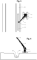
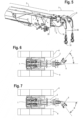
- tilt angle of boom head means the angle of offset between the boom head and the centerline of the boom, as illustrated by angle ⁇ in FIGURE 6 and 7 .
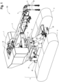
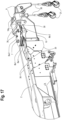
- Pipe-laying vehicle 100 may include an upper rotator frame assembly 1 carrying an extendible boom assembly 2, a tilt frame assembly 3 supporting upper rotator frame assembly 1, and a crawler frame assembly 4 to support and propel vehicle 100.
- extendable boom assembly 2 may include boom winches 22, winch cables 30, extendable boom outer stage 36, extendable boom second stage 37 and extendable boom third stage 20.
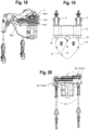
- Angle boom assembly 5 may be attached to extendable boom third stage 20, and may include the parts assembled as shown in FIGURES 1 , 13-16 and 21 , including angle boom cylinder 6, angle boom pivot shaft 7, redirection sheave 8 and sheave head assembly 9 (standard wrecker sheave head assemblies, currently available from Miller Industries Towing Equipment Inc., for example, which allow the winch cables to align with the load).
- Angle boom 10 is the weldment of the angle boom, and includes angle boom pivot bushings 11, angle boom cylinder rod shaft 12 (the pivot shaft that attaches angle boom cylinders 6 to angle boom 10), and angle boom cylinder base shaft 13 (the pivot shaft that attaches angle boom cylinders 6 to extendable boom third stage 20).
- Angle boom cylindrical portions 10a are part of angle boom 10 (see, e.g., FIGURES 13, 15 and 19 ).
- angle boom assembly 5 includes redirection sheave bottom mounting plate 14, redirection sheave center mounting plate 15 and redirection sheave top mounting plate 16, which together hold redirection sheaves 8 in place.
- the two lower redirection sheaves 8a redirect one winch cable to right sheave head assembly 9.
- the two upper redirection sheaves 8b redirect the other winch cable to left sheave head assembly 9.
- the second set of redirection sheaves 8a-2, 8b-2 turn the winch cables running through sheave head pivot tubes 35 (carried by angle boom cylinder portions 10a) to sheave head assembly 9.
- extendable boom third stage 20 is the innermost boom stage of extendable boom assembly 2, and is the stage that angle boom pivot shaft 7 and angle boom assembly 5 mount to.
- Dual boom winches 22 may be carried on a top portion of extendable boom assembly 2, to spool winch cables 30 along angle boom assembly 5, terminating in dual winch hooks 31.
- Boom lift cylinder 23 provides the motive force to lift extendable boom assembly 2.
- extendable boom outer stage 36 is the weldment that boom winches 22 mount to.
- angle boom pivot shaft retainer plate 18 connects angle boom pivot shaft 7 to extendable boom third stage 20.
- Retainer nut 19 holds redirection sheaves 8 and redirection plates 14, 15, 16 in place.
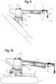
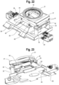
- tilt frame assembly 3 includes leveling frame 26 and rotator platform 27, supported by crawler frame 38. As shown in FIGURES 8-12 , tilt frame assembly 3 may be selectively tilted by rotator platform leveling cylinders 24 and rotator platform side leveling cylinders 25.
- Rotator platform leveling cylinder shaft 39 attaches the rotator platform leveling cylinders 24 between the crawler frame 38 and the leveling frame 26.
- Rotator platform leveling pivot shaft 40 attaches the leveling frame 26 to the crawler frame 38 (the shaft the leveling frame 26 pivots on).
- Rotator platform side leveling cylinder shaft 41 attaches the rotator platform side leveling cylinders 25 to the rotator platform 27.
- Rotator platform side leveling pivot shaft 42 attaches the rotator platform 27 to the leveling frame 26 (the shaft the rotator platform pivots on).
- Rotator platform side leveling cylinder pivot plate 43 attaches the rotator platform side leveling cylinders 25 to the leveling frame 26.
- Rotation bearing 21 allows upper rotator frame assembly 1 to rotate relative to tilt frame assembly 3.
- front stabilizer winch 29 may be used to secure vehicle 100 to support vehicles or fixed objects located above vehicle 100 on a steep hill, to secure vehicle 100.
- Rear stabilizer winch 28 (see FIGURES 1 and 11 ) may be used to pull a pipe cart up-grade, for example, to deliver additional pipe sections.
- pipe-laying vehicle 100 which forms a preferred embodiment of the present invention, can be provided with one or more of the following capabilities, as desired:
Landscapes
- Engineering & Computer Science (AREA)
- Mechanical Engineering (AREA)
- General Engineering & Computer Science (AREA)
- Combustion & Propulsion (AREA)
- Chemical & Material Sciences (AREA)
- Ocean & Marine Engineering (AREA)
- Transportation (AREA)
- Agronomy & Crop Science (AREA)
- Life Sciences & Earth Sciences (AREA)
- Forklifts And Lifting Vehicles (AREA)
- Soil Working Implements (AREA)
- Refuge Islands, Traffic Blockers, Or Guard Fence (AREA)
- Jib Cranes (AREA)
Claims (15)
- Véhicule autopropulsé (100) pour la pose de deux sections de tuyau individuelles (33) ou plus à l'intérieur d'une ou de plusieurs tranchées (34) situées sur un terrain en pente, le véhicule comprenant :un atterrisseur (4) supportant un châssis de véhicule (3), dans lequel l'atterrisseur (4) est capable de remonter le terrain en pente ;une plate-forme rotative (1) portée par le châssis de véhicule (4) ;et une flèche (2) portée par la plate-forme rotative (1) ;caractérisé pardeux câbles de treuil indépendants (30) configurés pour soulever et positionner les deux sections de tuyau individuelles (33) ou plus ;la flèche (2) ayant une tête de flèche (5) pouvant être positionnée selon un angle d'inclinaison (β) décalé par rapport à un axe longitudinal formant une ligne centrale de la flèche (2), dans lequel la tête de flèche inclinée (5) utilise les deux câbles de treuil indépendants (30) pour soulever et positionner les deux sections de tuyau individuelles (33) ou plus ;moyennant quoi le véhicule (100) peut être utilisé pour soulever séquentiellement les deux sections de tuyau ou plus, une à la fois, et pour faire pivoter et positionner les sections de tuyau (33) dans une tranchée (34), de bout en bout, sans avoir besoin de déplacer le véhicule (100).
- Véhicule (100) selon la revendication 1, dans lequel l'angle d'inclinaison (β) de la tête de flèche inclinée (5) est un angle compris entre 50° et 59° environ.
- Véhicule (100) selon la revendication 1, dans lequel le véhicule (100) est capable de poser des sections de tuyau individuelles (33) qui ont des longueurs différentes et des diamètres différents.
- Véhicule (100) selon la revendication 1, dans lequel la plate-forme rotative (1) est capable d'être maintenue dans un plan horizontal de niveau par rapport au terrain en pente, tandis que le véhicule (100) est utilisé pour poser les deux sections de tuyau individuels (33) ou plus dans les tranchées (34).
- Véhicule (100) selon la revendication 1, dans lequel un pivot de la tête de flèche inclinée (5), et un pivot des deux câbles de treuil (30), partagent un point central commun, permettant ainsi un changement non substantiel de hauteur de crochet lorsqu'un angle d'inclinaison (β) de la tête de flèche inclinée est modifié pour aligner l'une des sections de tuyau individuelles (33) avec la tranchée (34).
- Véhicule (100) selon la revendication 1, dans lequel la plate-forme rotative (1) est capable d'effectuer une rotation continue de 360°, l'atterrisseur (4) comprend un atterrisseur à chenilles (4) et un moteur est monté sur la plate-forme rotative (1).
- Véhicule (100) selon la revendication 1, dans lequel le véhicule est capable de se déplacer le long de pentes allant jusqu'à environ 45° à 50° d'avant en arrière et jusqu'à 15° d'un côté à l'autre.
- Véhicule (100) selon la revendication 1, dans lequel le déplacement du véhicule est commandé à distance.
- Véhicule (100) selon la revendication 1, dans lequel la flèche a une capacité étendue d'au moins 9 071,85 kilogrammes (20 000 livres) selon un angle de flèche de 30°, et le véhicule peut creuser des sections de tuyau (33) jusqu'à 106,68 cm (42 pouces) de diamètre extérieur et jusqu'à 12,18 mètres (40 pieds) de longueur.
- Véhicule (100) selon la revendication 1, comprenant également deux treuils (22) de 15 875,73 kilogrammes (35 000 livres) et dans lequel la flèche (2) est capable d'un angle de flèche maximal de 60°.
- Véhicule (100) selon la revendication 1, comprenant également des treuils de stabilisation montés à l'avant et à l'arrière de l'atterrisseur (4), et un treuil ascendant (28) pour faciliter la montée du véhicule sur des pentes raides.
- Véhicule (100) selon la revendication 1, comprenant également un treuil descendant (29) pouvant être utilisé pour tirer un chariot de transport de tuyaux, améliorer et délivrer des sections de tuyau supplémentaires (33).
- Véhicule (100) selon la revendication 1, dans lequel la plate-forme rotative (1) incorpore un contrepoids extensible.
- Procédé d'utilisation d'un véhicule autopropulsé (100) pour poser deux sections de tuyau individuelles (33) ou plus à l'intérieur d'une ou de plusieurs tranchées (34) situées sur un terrain en pente, le véhicule (100) ayant un atterrisseur (4) capable de remonter le terrain en pente, un châssis de véhicule (3) supportant une plate-forme rotative (1) et une flèche (2) portée par la plate-forme rotative (1), comprenant les étapes de caractérisation suivantes :
tout en maintenant la plate-forme rotative (1) dans un plan sensiblement horizontal de niveau par rapport au terrain en pente, l'utilisation de la flèche (2) et d'une tête de flèche inclinée associée (5) pouvant être positionnée selon un angle d'inclinaison (β) décalé par rapport à un axe longitudinal formant une ligne centrale de la flèche (2), pour manipuler deux câbles de treuil indépendants (30) afin de soulever et de positionner les deux sections de tuyau individuelles (33) ou plus, moyennant quoi le véhicule (100) peut être utilisé pour soulever séquentiellement les sections de tuyau individuelles (33), une à la fois, et pour faire pivoter et positionner les sections de tuyau individuelles (33) dans une tranchée (34), de bout en bout, sans avoir besoin de déplacer le véhicule (100) . - Procédé selon la revendication 14, dans lequel un pivot de la tête de flèche inclinée (5), et un pivot des deux câbles de treuil (30), partagent un point central commun, permettant ainsi un changement non substantiel de hauteur de crochet lorsque l'angle d'inclinaison de la tête de flèche inclinée (5) est modifié pour aligner une section de tuyau (33) avec la tranchée (34).
Applications Claiming Priority (2)
| Application Number | Priority Date | Filing Date | Title |
|---|---|---|---|
| US15/794,446 US10220921B1 (en) | 2017-10-26 | 2017-10-26 | Pipe-laying vehicle with rotator platform leveling system |
| PCT/US2018/050557 WO2019083630A1 (fr) | 2017-10-26 | 2018-09-12 | Véhicule à poser les tuyaux avec système de mise à niveau de plate-forme de rotateur |
Publications (4)
| Publication Number | Publication Date |
|---|---|
| EP3701093A1 EP3701093A1 (fr) | 2020-09-02 |
| EP3701093A4 EP3701093A4 (fr) | 2021-01-27 |
| EP3701093B1 true EP3701093B1 (fr) | 2024-03-13 |
| EP3701093C0 EP3701093C0 (fr) | 2024-03-13 |
Family
ID=65496038
Family Applications (1)
| Application Number | Title | Priority Date | Filing Date |
|---|---|---|---|
| EP18870439.9A Active EP3701093B1 (fr) | 2017-10-26 | 2018-09-12 | Véhicule à poser les tuyaux avec système de mise à niveau de plate-forme de rotateur |
Country Status (6)
| Country | Link |
|---|---|
| US (2) | US10220921B1 (fr) |
| EP (1) | EP3701093B1 (fr) |
| CN (1) | CN111315934B (fr) |
| AU (1) | AU2018355064B2 (fr) |
| MX (1) | MX2020004096A (fr) |
| WO (1) | WO2019083630A1 (fr) |
Families Citing this family (17)
| Publication number | Priority date | Publication date | Assignee | Title |
|---|---|---|---|---|
| US9261220B2 (en) * | 2012-08-02 | 2016-02-16 | Tt Technologies, Inc. | Winch boom and method for trench less replacement |
| CA2974274A1 (fr) | 2017-07-21 | 2019-01-21 | Brandt Equipment Solutions Ltd. | Machine pose-tubes dotee de treuils symetriques |
| US10220921B1 (en) * | 2017-10-26 | 2019-03-05 | Miller Towing Equipment, Inc. | Pipe-laying vehicle with rotator platform leveling system |
| US11584456B2 (en) * | 2019-07-26 | 2023-02-21 | Caterpillar Global Mining Equipment Llc | Undercarriage assembly for a machine |
| CN111056438A (zh) * | 2019-11-25 | 2020-04-24 | 安徽春华智能科技有限公司 | 一种起重机防摇摆装置及其工作方法 |
| CN110863525A (zh) * | 2019-11-29 | 2020-03-06 | 江苏旭正信息科技有限公司 | 适用于钢管起出的设备 |
| WO2021204938A1 (fr) * | 2020-04-08 | 2021-10-14 | Itrec B.V. | Grue marine à flèche articulée |
| CN111847274B (zh) * | 2020-07-27 | 2022-05-27 | 湖北武铁山桥轨道装备有限公司 | 一种道岔换轨作业车及换轨方法 |
| CN113682984B (zh) * | 2021-08-31 | 2024-10-29 | 南京市物联网与集成电路设计产业创新中心有限公司 | 一种山地平衡起吊车 |
| CN113682981B (zh) * | 2021-09-09 | 2023-03-10 | 大洋泊车股份有限公司 | 一种登高平台消防车伸缩臂 |
| CN116142999B (zh) * | 2023-03-10 | 2026-04-17 | 徐工集团工程机械股份有限公司建设机械分公司 | 吊管机 |
| CN116281670B (zh) * | 2023-03-10 | 2026-04-17 | 徐工集团工程机械股份有限公司建设机械分公司 | 吊管机 |
| CN116573548B (zh) * | 2023-03-10 | 2026-03-17 | 徐工集团工程机械股份有限公司建设机械分公司 | 吊管机 |
| CN116199138B (zh) * | 2023-03-10 | 2026-02-13 | 徐工集团工程机械股份有限公司建设机械分公司 | 吊管机 |
| IT202300005121A1 (it) * | 2023-03-17 | 2024-09-17 | Scaip S P A | Macchina per la posa di tubazioni con stabilita’ migliorata |
| CN116497918B (zh) * | 2023-04-14 | 2023-10-13 | 广东金秋建设工程有限公司 | 一种高架桥路面给排水施工作业方法 |
| CN116425040B (zh) * | 2023-05-08 | 2025-11-11 | 徐工集团工程机械股份有限公司建设机械分公司 | 运管机的控制系统 |
Family Cites Families (51)
| Publication number | Priority date | Publication date | Assignee | Title |
|---|---|---|---|---|
| US2789716A (en) | 1954-10-15 | 1957-04-23 | Lloyd J Wolf | Mobile pipe handling mechanism |
| DE1246200B (de) | 1964-04-23 | 1967-08-03 | Beteiligungs & Patentverw Gmbh | Einrichtung zum Verhueten von Pendelungen einer mittels Seilen an einem seitwaerts schwenkbaren Kranausleger haengenden Last |
| US3325029A (en) | 1965-03-26 | 1967-06-13 | Lonnie D Rigsby | Bale unloading clamp device |
| US3657786A (en) | 1970-03-11 | 1972-04-25 | George C Wiswell Jr | Laying of subaqueous pipe |
| GB1376327A (en) | 1971-12-22 | 1974-12-04 | Jarvis Geochemical Ltd | Crane assemblies |
| US3989150A (en) * | 1975-01-10 | 1976-11-02 | Stephenson James M | Pipe carrying attachment for construction equipment |
| IT1071441B (it) | 1976-09-07 | 1985-04-10 | Fiat Allis Macch Movi | Macchina posatubi per oleodotti..condotte e simili |
| US4130204A (en) * | 1977-08-26 | 1978-12-19 | Pickard Kenneth L | Side boom pipe laying crane with pipe section alignment feature |
| FR2445291A1 (fr) | 1978-12-28 | 1980-07-25 | Casteran Jean | Systeme de suspension d'un fardeau, notamment pour grue |
| US4362435A (en) * | 1979-07-10 | 1982-12-07 | Henry John T | Apparatus for laying pipe |
| EP0048307A1 (fr) * | 1980-09-23 | 1982-03-31 | Ballast-Nedam Groep N.V. | Procédé et dispositif de pose d'un conduit de tuyaux et conduit de tuyau posé à l'aide de ce procédé |
| JPS6173289A (ja) | 1984-09-17 | 1986-04-15 | Citizen Watch Co Ltd | マイクロフロツピデイスクドライブ用テストデイスク |
| US5765965A (en) * | 1991-06-24 | 1998-06-16 | Halliburton Nus Corporation | Apparatus for in situ installation of underground containment barriers under contaminated lands |
| JPH0778348B2 (ja) | 1992-06-16 | 1995-08-23 | 日本ビソー株式会社 | 作業ケージ用吊下げ装置 |
| JP3168083B2 (ja) * | 1992-12-03 | 2001-05-21 | 岡本 俊仁 | 法面等の加工機械 |
| US5480201A (en) * | 1995-02-13 | 1996-01-02 | Mercer; George L. | Safety pipe handler |
| JPH09256626A (ja) | 1996-03-25 | 1997-09-30 | Nihon Bisoh Co Ltd | 建築物の外壁作業機の吊り下げ支持装置 |
| JPH10297868A (ja) | 1997-04-24 | 1998-11-10 | Niichi:Kk | 吊り治具 |
| US6105699A (en) * | 1998-06-15 | 2000-08-22 | Cameco Industries, Inc. | Heavy equipment apparatus that includes undercarriage with mobile tilting upper |
| WO1999066244A2 (fr) | 1998-06-19 | 1999-12-23 | Ryan Incorporated Eastern | Dispositif et procedes de mise en place et de presentation de pieces de forme allongee |
| US6173973B1 (en) * | 1998-07-09 | 2001-01-16 | Timberjack Inc. | Forestry machine swing-house leveling mechanism |
| DE50109335D1 (de) | 2000-01-25 | 2006-05-18 | Macmoter Spa | Rohrverleger |
| EP1265017B1 (fr) | 2001-06-07 | 2007-09-12 | Sea of Solutions B.V. | Navire de pose de conduites à grandes profondeur |
| JP4390468B2 (ja) | 2003-03-24 | 2009-12-24 | 株式会社小松製作所 | パイプレイヤ |
| US20050117973A1 (en) * | 2003-09-23 | 2005-06-02 | Nelson Jimmie P. | Method and system for preparing a trench and laying pipe in a trench |
| US7261493B2 (en) * | 2003-12-08 | 2007-08-28 | Trenchcraft, Inc. | Device and method for laying and joining pipe |
| CN2723413Y (zh) * | 2004-08-08 | 2005-09-07 | 鲍建 | 新型多功能吊管机 |
| KR100956995B1 (ko) | 2007-11-07 | 2010-05-11 | 볼보 컨스트럭션 이키프먼트 홀딩 스웨덴 에이비 | 산림장비 및 굴삭기용 레벨링 장치 |
| CA2631480A1 (fr) * | 2008-05-08 | 2009-11-08 | M. Patrick Mcnamara | Ensemble de bras articule approprie pour la pose de canalisations |
| CN102046450B (zh) * | 2008-05-29 | 2013-12-18 | 沃尔沃建筑设备公司 | 具有驾驶室升降机的管道铺设机 |
| GB0811437D0 (en) * | 2008-06-20 | 2008-07-30 | Saipem Spa | Pipe-laying vessel and method of laying a pipeline |
| CN201317619Y (zh) * | 2008-12-24 | 2009-09-30 | 石建忠 | 管道下沟用吊篮 |
| US8069592B2 (en) | 2009-01-20 | 2011-12-06 | Ellett William Anthony | Heavy equipment vehicle for laying pipe |
| AU2009230812A1 (en) * | 2009-07-24 | 2011-02-10 | Ekebol Pty Ltd | A recovery vehicle |
| CN201496651U (zh) * | 2009-09-09 | 2010-06-02 | 四川石油天然气建设工程有限责任公司 | 一种具有回转功能的山地布管机 |
| ITMI20091639A1 (it) * | 2009-09-25 | 2011-03-26 | Saipem Spa | Metodo e gruppo di sollevamento per abbandonare e/o recuperare una tubazione subacquea tramite un natante di posa e natante di posa equipaggiato con tale gruppo di sollevamento |
| US20110221215A1 (en) | 2010-03-12 | 2011-09-15 | Vestas Wind Systems A/S | Methods and apparatus for handling a tower section of a wind turbine with a crane |
| GB2482178B (en) | 2010-07-23 | 2013-07-03 | Pearse Gately | Device for placing articles in a trench |
| WO2012054961A1 (fr) * | 2010-10-26 | 2012-05-03 | John Eugene Hough | Dispositif de levage mobile avec équipement de levage auxiliaire |
| CA2836479C (fr) * | 2011-05-26 | 2016-05-24 | Lavalley Industries, Llc | Fixation permettant de monter ou de demonter un tuyau |
| WO2013113377A1 (fr) * | 2012-02-01 | 2013-08-08 | Vsl International Ag | Appareil et procédé de levage lourd |
| US9028196B2 (en) * | 2012-08-02 | 2015-05-12 | Miller Industries Towing Equipment, Inc. | Traveler roller |
| CN102976200B (zh) * | 2012-12-13 | 2014-12-03 | 中联重科股份有限公司 | 吊装控制方法、装置、系统及吊具和起重机械 |
| WO2014133400A1 (fr) * | 2013-03-01 | 2014-09-04 | Kelly Logging Company Ltd | Véhicule à utiliser sur des pentes raides |
| US20140252285A1 (en) | 2013-03-05 | 2014-09-11 | Kelly D. Genoe | Side Recovery Boom Apparatus for Tow Truck |
| KR102025327B1 (ko) * | 2013-05-27 | 2019-09-25 | 볼보 컨스트럭션 이큅먼트 에이비 | 붐 길이 조절되는 파이프 레이어 |
| ITMO20130168A1 (it) * | 2013-06-10 | 2014-12-11 | C M C S R L Societa Unipersonal E | Organo di presa equipaggiante veicoli per la movimentazione di carichi |
| US9746103B2 (en) * | 2014-01-29 | 2017-08-29 | Laurini Officine Meccaniche S.R.L. | Pipe laying machine and pipe laying method |
| US9346498B2 (en) | 2014-02-27 | 2016-05-24 | Towhaul Corporation | Gooseneck towing module and method of use |
| JP6173289B2 (ja) | 2014-11-01 | 2017-08-02 | 株式会社東京Bk足場 | 取付金具とそれを備えた仮設足場の構成部材 |
| US10220921B1 (en) * | 2017-10-26 | 2019-03-05 | Miller Towing Equipment, Inc. | Pipe-laying vehicle with rotator platform leveling system |
-
2017
- 2017-10-26 US US15/794,446 patent/US10220921B1/en active Active
-
2018
- 2018-09-12 AU AU2018355064A patent/AU2018355064B2/en active Active
- 2018-09-12 CN CN201880069129.4A patent/CN111315934B/zh active Active
- 2018-09-12 WO PCT/US2018/050557 patent/WO2019083630A1/fr not_active Ceased
- 2018-09-12 EP EP18870439.9A patent/EP3701093B1/fr active Active
- 2018-09-12 MX MX2020004096A patent/MX2020004096A/es unknown
-
2019
- 2019-02-05 US US16/267,839 patent/US10526054B2/en active Active
Also Published As
| Publication number | Publication date |
|---|---|
| WO2019083630A1 (fr) | 2019-05-02 |
| US20190168846A1 (en) | 2019-06-06 |
| EP3701093A4 (fr) | 2021-01-27 |
| US10526054B2 (en) | 2020-01-07 |
| CN111315934A (zh) | 2020-06-19 |
| US10220921B1 (en) | 2019-03-05 |
| AU2018355064A1 (en) | 2020-04-23 |
| EP3701093C0 (fr) | 2024-03-13 |
| BR112020006691A2 (pt) | 2020-10-06 |
| AU2018355064B2 (en) | 2023-09-21 |
| CN111315934B (zh) | 2022-04-19 |
| MX2020004096A (es) | 2020-09-25 |
| EP3701093A1 (fr) | 2020-09-02 |
Similar Documents
| Publication | Publication Date | Title |
|---|---|---|
| US10526054B2 (en) | Pipe-laying vehicle with rotator platform leveling system | |
| KR101305867B1 (ko) | 캡 라이저를 구비한 파이프 부설기 | |
| US8783477B2 (en) | Lightweight high-performance pipelayer | |
| US9746103B2 (en) | Pipe laying machine and pipe laying method | |
| KR20040086493A (ko) | 파이프레이어 | |
| US20090260265A1 (en) | Accessory For Converting Excavators | |
| US4877091A (en) | Augering apparatus and drilling rig | |
| US4336889A (en) | Ring supported truck crane and method of setting up | |
| JPS5926600B2 (ja) | リフト | |
| US20120241402A1 (en) | Formulations for c-met kinase inhibitors | |
| US20250314332A1 (en) | Apparatus and Method for Transporting and Laying Pipe for a Pipeline | |
| US4218045A (en) | Mobile heavy lift mechanism | |
| US11149876B2 (en) | Pipeline laying apparatus and method for crossing steep terrain | |
| US20190357422A1 (en) | Pipe layer attachment for an excavator | |
| US10065841B2 (en) | Compact stowable luffing jib for a crane | |
| US6969215B2 (en) | Method and apparatus for laying pipe on an incline | |
| US4491450A (en) | Pick-up and laydown machine | |
| US20050199316A1 (en) | Method of winching cut timber in a forest and a machine designed to accomplish this | |
| CN213569257U (zh) | 履带式吊装运管车 | |
| BR112020006691B1 (pt) | Veículo de autopropulsão para colocar uma tubulação com um sistema de nivelamento de plataforma rotativa e método para usar um veículo de autopropulsão | |
| US20240375916A1 (en) | Pipe laying machine with improved stability | |
| US9834125B2 (en) | Telescoping pole rack | |
| RU1074U1 (ru) | Землеройно-крановый агрегат | |
| US3015471A (en) | Spar tree | |
| EP2546560A1 (fr) | Procédé de pose d'un pipeline et réservoir de récupération pour son utilisation |
Legal Events
| Date | Code | Title | Description |
|---|---|---|---|
| STAA | Information on the status of an ep patent application or granted ep patent |
Free format text: STATUS: THE INTERNATIONAL PUBLICATION HAS BEEN MADE |
|
| PUAI | Public reference made under article 153(3) epc to a published international application that has entered the european phase |
Free format text: ORIGINAL CODE: 0009012 |
|
| STAA | Information on the status of an ep patent application or granted ep patent |
Free format text: STATUS: REQUEST FOR EXAMINATION WAS MADE |
|
| 17P | Request for examination filed |
Effective date: 20200324 |
|
| AK | Designated contracting states |
Kind code of ref document: A1 Designated state(s): AL AT BE BG CH CY CZ DE DK EE ES FI FR GB GR HR HU IE IS IT LI LT LU LV MC MK MT NL NO PL PT RO RS SE SI SK SM TR |
|
| AX | Request for extension of the european patent |
Extension state: BA ME |
|
| A4 | Supplementary search report drawn up and despatched |
Effective date: 20210114 |
|
| RIC1 | Information provided on ipc code assigned before grant |
Ipc: B66C 23/44 20060101ALI20201223BHEP Ipc: F16L 1/06 20060101ALI20201223BHEP Ipc: B66C 13/08 20060101ALI20201223BHEP Ipc: F16L 1/028 20060101AFI20201223BHEP Ipc: B66C 23/62 20060101ALI20201223BHEP |
|
| DAV | Request for validation of the european patent (deleted) | ||
| DAX | Request for extension of the european patent (deleted) | ||
| REG | Reference to a national code |
Ref country code: DE Ref legal event code: R079 Free format text: PREVIOUS MAIN CLASS: E02F0005100000 Ipc: F16L0001028000 Ref country code: DE Ref legal event code: R079 Ref document number: 602018066686 Country of ref document: DE Free format text: PREVIOUS MAIN CLASS: E02F0005100000 Ipc: F16L0001028000 |
|
| RIC1 | Information provided on ipc code assigned before grant |
Ipc: F16L 1/06 20060101ALI20231017BHEP Ipc: B66C 23/62 20060101ALI20231017BHEP Ipc: B66C 13/08 20060101ALI20231017BHEP Ipc: B66C 23/44 20060101ALI20231017BHEP Ipc: F16L 1/028 20060101AFI20231017BHEP |
|
| GRAP | Despatch of communication of intention to grant a patent |
Free format text: ORIGINAL CODE: EPIDOSNIGR1 |
|
| STAA | Information on the status of an ep patent application or granted ep patent |
Free format text: STATUS: GRANT OF PATENT IS INTENDED |
|
| INTG | Intention to grant announced |
Effective date: 20231130 |
|
| GRAS | Grant fee paid |
Free format text: ORIGINAL CODE: EPIDOSNIGR3 |
|
| GRAA | (expected) grant |
Free format text: ORIGINAL CODE: 0009210 |
|
| STAA | Information on the status of an ep patent application or granted ep patent |
Free format text: STATUS: THE PATENT HAS BEEN GRANTED |
|
| AK | Designated contracting states |
Kind code of ref document: B1 Designated state(s): AL AT BE BG CH CY CZ DE DK EE ES FI FR GB GR HR HU IE IS IT LI LT LU LV MC MK MT NL NO PL PT RO RS SE SI SK SM TR |
|
| REG | Reference to a national code |
Ref country code: GB Ref legal event code: FG4D |
|
| REG | Reference to a national code |
Ref country code: CH Ref legal event code: EP |
|
| REG | Reference to a national code |
Ref country code: DE Ref legal event code: R096 Ref document number: 602018066686 Country of ref document: DE |
|
| REG | Reference to a national code |
Ref country code: IE Ref legal event code: FG4D |
|
| U01 | Request for unitary effect filed |
Effective date: 20240327 |
|
| U07 | Unitary effect registered |
Designated state(s): AT BE BG DE DK EE FI FR IT LT LU LV MT NL PT SE SI Effective date: 20240410 |
|
| PG25 | Lapsed in a contracting state [announced via postgrant information from national office to epo] |
Ref country code: GR Free format text: LAPSE BECAUSE OF FAILURE TO SUBMIT A TRANSLATION OF THE DESCRIPTION OR TO PAY THE FEE WITHIN THE PRESCRIBED TIME-LIMIT Effective date: 20240614 |
|
| PG25 | Lapsed in a contracting state [announced via postgrant information from national office to epo] |
Ref country code: HR Free format text: LAPSE BECAUSE OF FAILURE TO SUBMIT A TRANSLATION OF THE DESCRIPTION OR TO PAY THE FEE WITHIN THE PRESCRIBED TIME-LIMIT Effective date: 20240313 Ref country code: RS Free format text: LAPSE BECAUSE OF FAILURE TO SUBMIT A TRANSLATION OF THE DESCRIPTION OR TO PAY THE FEE WITHIN THE PRESCRIBED TIME-LIMIT Effective date: 20240613 |
|
| PG25 | Lapsed in a contracting state [announced via postgrant information from national office to epo] |
Ref country code: ES Free format text: LAPSE BECAUSE OF FAILURE TO SUBMIT A TRANSLATION OF THE DESCRIPTION OR TO PAY THE FEE WITHIN THE PRESCRIBED TIME-LIMIT Effective date: 20240313 |
|
| PG25 | Lapsed in a contracting state [announced via postgrant information from national office to epo] |
Ref country code: RS Free format text: LAPSE BECAUSE OF FAILURE TO SUBMIT A TRANSLATION OF THE DESCRIPTION OR TO PAY THE FEE WITHIN THE PRESCRIBED TIME-LIMIT Effective date: 20240613 Ref country code: NO Free format text: LAPSE BECAUSE OF FAILURE TO SUBMIT A TRANSLATION OF THE DESCRIPTION OR TO PAY THE FEE WITHIN THE PRESCRIBED TIME-LIMIT Effective date: 20240613 Ref country code: HR Free format text: LAPSE BECAUSE OF FAILURE TO SUBMIT A TRANSLATION OF THE DESCRIPTION OR TO PAY THE FEE WITHIN THE PRESCRIBED TIME-LIMIT Effective date: 20240313 Ref country code: GR Free format text: LAPSE BECAUSE OF FAILURE TO SUBMIT A TRANSLATION OF THE DESCRIPTION OR TO PAY THE FEE WITHIN THE PRESCRIBED TIME-LIMIT Effective date: 20240614 Ref country code: ES Free format text: LAPSE BECAUSE OF FAILURE TO SUBMIT A TRANSLATION OF THE DESCRIPTION OR TO PAY THE FEE WITHIN THE PRESCRIBED TIME-LIMIT Effective date: 20240313 |
|
| U20 | Renewal fee for the european patent with unitary effect paid |
Year of fee payment: 7 Effective date: 20240823 |
|
| PG25 | Lapsed in a contracting state [announced via postgrant information from national office to epo] |
Ref country code: IS Free format text: LAPSE BECAUSE OF FAILURE TO SUBMIT A TRANSLATION OF THE DESCRIPTION OR TO PAY THE FEE WITHIN THE PRESCRIBED TIME-LIMIT Effective date: 20240713 |
|
| PG25 | Lapsed in a contracting state [announced via postgrant information from national office to epo] |
Ref country code: SM Free format text: LAPSE BECAUSE OF FAILURE TO SUBMIT A TRANSLATION OF THE DESCRIPTION OR TO PAY THE FEE WITHIN THE PRESCRIBED TIME-LIMIT Effective date: 20240313 |
|
| PG25 | Lapsed in a contracting state [announced via postgrant information from national office to epo] |
Ref country code: CZ Free format text: LAPSE BECAUSE OF FAILURE TO SUBMIT A TRANSLATION OF THE DESCRIPTION OR TO PAY THE FEE WITHIN THE PRESCRIBED TIME-LIMIT Effective date: 20240313 |
|
| PG25 | Lapsed in a contracting state [announced via postgrant information from national office to epo] |
Ref country code: PL Free format text: LAPSE BECAUSE OF FAILURE TO SUBMIT A TRANSLATION OF THE DESCRIPTION OR TO PAY THE FEE WITHIN THE PRESCRIBED TIME-LIMIT Effective date: 20240313 |
|
| PG25 | Lapsed in a contracting state [announced via postgrant information from national office to epo] |
Ref country code: SK Free format text: LAPSE BECAUSE OF FAILURE TO SUBMIT A TRANSLATION OF THE DESCRIPTION OR TO PAY THE FEE WITHIN THE PRESCRIBED TIME-LIMIT Effective date: 20240313 |
|
| PG25 | Lapsed in a contracting state [announced via postgrant information from national office to epo] |
Ref country code: SM Free format text: LAPSE BECAUSE OF FAILURE TO SUBMIT A TRANSLATION OF THE DESCRIPTION OR TO PAY THE FEE WITHIN THE PRESCRIBED TIME-LIMIT Effective date: 20240313 Ref country code: SK Free format text: LAPSE BECAUSE OF FAILURE TO SUBMIT A TRANSLATION OF THE DESCRIPTION OR TO PAY THE FEE WITHIN THE PRESCRIBED TIME-LIMIT Effective date: 20240313 Ref country code: RO Free format text: LAPSE BECAUSE OF FAILURE TO SUBMIT A TRANSLATION OF THE DESCRIPTION OR TO PAY THE FEE WITHIN THE PRESCRIBED TIME-LIMIT Effective date: 20240313 Ref country code: PL Free format text: LAPSE BECAUSE OF FAILURE TO SUBMIT A TRANSLATION OF THE DESCRIPTION OR TO PAY THE FEE WITHIN THE PRESCRIBED TIME-LIMIT Effective date: 20240313 Ref country code: IS Free format text: LAPSE BECAUSE OF FAILURE TO SUBMIT A TRANSLATION OF THE DESCRIPTION OR TO PAY THE FEE WITHIN THE PRESCRIBED TIME-LIMIT Effective date: 20240713 Ref country code: CZ Free format text: LAPSE BECAUSE OF FAILURE TO SUBMIT A TRANSLATION OF THE DESCRIPTION OR TO PAY THE FEE WITHIN THE PRESCRIBED TIME-LIMIT Effective date: 20240313 |
|
| REG | Reference to a national code |
Ref country code: DE Ref legal event code: R097 Ref document number: 602018066686 Country of ref document: DE |
|
| PLBE | No opposition filed within time limit |
Free format text: ORIGINAL CODE: 0009261 |
|
| STAA | Information on the status of an ep patent application or granted ep patent |
Free format text: STATUS: NO OPPOSITION FILED WITHIN TIME LIMIT |
|
| 26N | No opposition filed |
Effective date: 20241216 |
|
| PG25 | Lapsed in a contracting state [announced via postgrant information from national office to epo] |
Ref country code: MC Free format text: LAPSE BECAUSE OF FAILURE TO SUBMIT A TRANSLATION OF THE DESCRIPTION OR TO PAY THE FEE WITHIN THE PRESCRIBED TIME-LIMIT Effective date: 20240313 |
|
| REG | Reference to a national code |
Ref country code: CH Ref legal event code: PL |
|
| GBPC | Gb: european patent ceased through non-payment of renewal fee |
Effective date: 20240912 |
|
| PG25 | Lapsed in a contracting state [announced via postgrant information from national office to epo] |
Ref country code: GB Free format text: LAPSE BECAUSE OF NON-PAYMENT OF DUE FEES Effective date: 20240912 |
|
| PG25 | Lapsed in a contracting state [announced via postgrant information from national office to epo] |
Ref country code: CH Free format text: LAPSE BECAUSE OF NON-PAYMENT OF DUE FEES Effective date: 20240930 |
|
| PG25 | Lapsed in a contracting state [announced via postgrant information from national office to epo] |
Ref country code: IE Free format text: LAPSE BECAUSE OF NON-PAYMENT OF DUE FEES Effective date: 20240912 |
|
| U20 | Renewal fee for the european patent with unitary effect paid |
Year of fee payment: 8 Effective date: 20250707 |
|
| PG25 | Lapsed in a contracting state [announced via postgrant information from national office to epo] |
Ref country code: CY Free format text: LAPSE BECAUSE OF FAILURE TO SUBMIT A TRANSLATION OF THE DESCRIPTION OR TO PAY THE FEE WITHIN THE PRESCRIBED TIME-LIMIT; INVALID AB INITIO Effective date: 20180912 |
|
| PG25 | Lapsed in a contracting state [announced via postgrant information from national office to epo] |
Ref country code: HU Free format text: LAPSE BECAUSE OF FAILURE TO SUBMIT A TRANSLATION OF THE DESCRIPTION OR TO PAY THE FEE WITHIN THE PRESCRIBED TIME-LIMIT; INVALID AB INITIO Effective date: 20180912 |