EP3701257B1 - Apparatus and method for improved corrosion thinning detection - Google Patents
Apparatus and method for improved corrosion thinning detection Download PDFInfo
- Publication number
- EP3701257B1 EP3701257B1 EP18870759.0A EP18870759A EP3701257B1 EP 3701257 B1 EP3701257 B1 EP 3701257B1 EP 18870759 A EP18870759 A EP 18870759A EP 3701257 B1 EP3701257 B1 EP 3701257B1
- Authority
- EP
- European Patent Office
- Prior art keywords
- frame
- pipe
- phased array
- array probe
- curved surface
- Prior art date
- Legal status (The legal status is an assumption and is not a legal conclusion. Google has not performed a legal analysis and makes no representation as to the accuracy of the status listed.)
- Active
Links
Images



Classifications
-
- G—PHYSICS
- G01—MEASURING; TESTING
- G01N—INVESTIGATING OR ANALYSING MATERIALS BY DETERMINING THEIR CHEMICAL OR PHYSICAL PROPERTIES
- G01N29/00—Investigating or analysing materials by the use of ultrasonic, sonic or infrasonic waves; Visualisation of the interior of objects by transmitting ultrasonic or sonic waves through the object
- G01N29/22—Details, e.g. general constructional or apparatus details
- G01N29/225—Supports, positioning or alignment in moving situation
- G01N29/226—Handheld or portable devices
-
- G—PHYSICS
- G01—MEASURING; TESTING
- G01N—INVESTIGATING OR ANALYSING MATERIALS BY DETERMINING THEIR CHEMICAL OR PHYSICAL PROPERTIES
- G01N29/00—Investigating or analysing materials by the use of ultrasonic, sonic or infrasonic waves; Visualisation of the interior of objects by transmitting ultrasonic or sonic waves through the object
- G01N29/22—Details, e.g. general constructional or apparatus details
- G01N29/26—Arrangements for orientation or scanning by relative movement of the head and the sensor
- G01N29/265—Arrangements for orientation or scanning by relative movement of the head and the sensor by moving the sensor relative to a stationary material
-
- G—PHYSICS
- G01—MEASURING; TESTING
- G01N—INVESTIGATING OR ANALYSING MATERIALS BY DETERMINING THEIR CHEMICAL OR PHYSICAL PROPERTIES
- G01N29/00—Investigating or analysing materials by the use of ultrasonic, sonic or infrasonic waves; Visualisation of the interior of objects by transmitting ultrasonic or sonic waves through the object
- G01N29/04—Analysing solids
- G01N29/043—Analysing solids in the interior, e.g. by shear waves
-
- G—PHYSICS
- G01—MEASURING; TESTING
- G01B—MEASURING LENGTH, THICKNESS OR SIMILAR LINEAR DIMENSIONS; MEASURING ANGLES; MEASURING AREAS; MEASURING IRREGULARITIES OF SURFACES OR CONTOURS
- G01B17/00—Measuring arrangements characterised by the use of infrasonic, sonic or ultrasonic vibrations
- G01B17/02—Measuring arrangements characterised by the use of infrasonic, sonic or ultrasonic vibrations for measuring thickness
-
- G—PHYSICS
- G01—MEASURING; TESTING
- G01N—INVESTIGATING OR ANALYSING MATERIALS BY DETERMINING THEIR CHEMICAL OR PHYSICAL PROPERTIES
- G01N17/00—Investigating resistance of materials to the weather, to corrosion, or to light
-
- G—PHYSICS
- G01—MEASURING; TESTING
- G01N—INVESTIGATING OR ANALYSING MATERIALS BY DETERMINING THEIR CHEMICAL OR PHYSICAL PROPERTIES
- G01N29/00—Investigating or analysing materials by the use of ultrasonic, sonic or infrasonic waves; Visualisation of the interior of objects by transmitting ultrasonic or sonic waves through the object
- G01N29/04—Analysing solids
-
- G—PHYSICS
- G01—MEASURING; TESTING
- G01N—INVESTIGATING OR ANALYSING MATERIALS BY DETERMINING THEIR CHEMICAL OR PHYSICAL PROPERTIES
- G01N29/00—Investigating or analysing materials by the use of ultrasonic, sonic or infrasonic waves; Visualisation of the interior of objects by transmitting ultrasonic or sonic waves through the object
- G01N29/04—Analysing solids
- G01N29/041—Analysing solids on the surface of the material, e.g. using Lamb, Rayleigh or shear waves
-
- G—PHYSICS
- G01—MEASURING; TESTING
- G01N—INVESTIGATING OR ANALYSING MATERIALS BY DETERMINING THEIR CHEMICAL OR PHYSICAL PROPERTIES
- G01N29/00—Investigating or analysing materials by the use of ultrasonic, sonic or infrasonic waves; Visualisation of the interior of objects by transmitting ultrasonic or sonic waves through the object
- G01N29/22—Details, e.g. general constructional or apparatus details
- G01N29/26—Arrangements for orientation or scanning by relative movement of the head and the sensor
- G01N29/262—Arrangements for orientation or scanning by relative movement of the head and the sensor by electronic orientation or focusing, e.g. with phased arrays
-
- G—PHYSICS
- G01—MEASURING; TESTING
- G01N—INVESTIGATING OR ANALYSING MATERIALS BY DETERMINING THEIR CHEMICAL OR PHYSICAL PROPERTIES
- G01N29/00—Investigating or analysing materials by the use of ultrasonic, sonic or infrasonic waves; Visualisation of the interior of objects by transmitting ultrasonic or sonic waves through the object
- G01N29/22—Details, e.g. general constructional or apparatus details
- G01N29/28—Details, e.g. general constructional or apparatus details providing acoustic coupling, e.g. water
-
- G—PHYSICS
- G01—MEASURING; TESTING
- G01N—INVESTIGATING OR ANALYSING MATERIALS BY DETERMINING THEIR CHEMICAL OR PHYSICAL PROPERTIES
- G01N2291/00—Indexing codes associated with group G01N29/00
- G01N2291/02—Indexing codes associated with the analysed material
- G01N2291/025—Change of phase or condition
- G01N2291/0258—Structural degradation, e.g. fatigue of composites, ageing of oils
-
- G—PHYSICS
- G01—MEASURING; TESTING
- G01N—INVESTIGATING OR ANALYSING MATERIALS BY DETERMINING THEIR CHEMICAL OR PHYSICAL PROPERTIES
- G01N2291/00—Indexing codes associated with group G01N29/00
- G01N2291/02—Indexing codes associated with the analysed material
- G01N2291/028—Material parameters
- G01N2291/0289—Internal structure, e.g. defects, grain size, texture
-
- G—PHYSICS
- G01—MEASURING; TESTING
- G01N—INVESTIGATING OR ANALYSING MATERIALS BY DETERMINING THEIR CHEMICAL OR PHYSICAL PROPERTIES
- G01N2291/00—Indexing codes associated with group G01N29/00
- G01N2291/26—Scanned objects
- G01N2291/263—Surfaces
- G01N2291/2634—Surfaces cylindrical from outside
Definitions
- the present invention is directed to apparatus for performing non-destructive evaluations of portions of pipes.
- the present invention is further directed to frame assemblies for use in apparatus for performing non-destructive evaluations of portions of pipes.
- Pipelines such as those used for the transmission of gases and liquids, are vulnerable to attack by internal and external corrosion, cracking, third party damage and manufacturing flaws. If a pipeline carrying water springs a leak or bursts, it can be a problem but it usually does not harm the environment. However, if a petroleum or chemical pipeline leaks or bursts, it can be an environmental disaster. If a pipeline related to a critical system fails, such as a coolant system in a nuclear reactor, an even more extreme disaster may occur. In an attempt to keep pipelines operating safely, periodic inspections are performed to find flaws and damage before they become cause for concern. Such periodic inspections may be carried out in a variety of ways.
- inspection personnel may use visual, X-ray, magnetic particle, ultrasonic and other inspection methods to evaluate the welds and ensure that they are of high quality. Similar methods are also commonly employed to inspect exposed pipelines at pre-determined intervals after such pipelines have been in service.
- Such ultrasonic inspections of piping are typically carried out using an ultrasonic sensor of circular shape about 0,635 cm (0.250 inches) in diameter which covers an area of about 0,316 cm 2 (.049 in 2 ).
- Such sensor is typically placed at various points on a grid of predetermined spacing which is laid out by the technician prior to taking readings with the sensor.
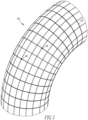
- Figure 1 shows an example of an arrangement for ultrasonic inspection of a 90° elbow 10 according to such prior art approach.
- a grid 12 (only a portion of which is shown in Figure 1 ) was laid out (e.g., via a paint marker) on the entire surface of elbow 10 prior to taking readings at the various points 14 (only two points are labeled in Figure 1 ) of grid 12 thereon.
- grid 12 would typically take at least two man hours to lay out on the surface of elbow 10 and placing the aforementioned sensor at all of the points on the grid and recording readings took would take at least an additional 45 minutes to record.
- nearly three hours or more time would be required to inspect a limited percentage of the wall of such a single 90° elbow. While such method may be effective for detecting rather large thinned areas, such method may not detect localized corrosion. Additionally, the frequency of such inspections may be limited due to the time/cost required.
- Embodiments of the present invention provide apparatuses and methods for performing non-destructive evaluation of piping which not only evaluate much percentages of the piping with greater resolution but can accomplish such evaluations in a much shorter time than conventional approaches.
- a system having a flexible phased array probe and a plurality of frame assemblies for use in an apparatus for performing ultrasonic evaluation of a portion of a pipe is provided.
- This first aspect is defined in claim 1.
- Each frame assembly comprises: a frame which is structured to cooperatively engage an outer surface of the pipe, the frame having a curved surface which is curved about an axis which, when the frame is engaged with the pipe generally coincides with the central longitudinal axis of the pipe, the curved surface is generally defined by a radius which is generally equal to an outer radius of the pipe, wherein the frame is structured to house the flexible phased array probe therein a fixed distance from the curved surface.
- the frame may include a main passage defined therein such that when the flexible phased array probe is housed in the frame the main passage is disposed between the flexible phased array probe and the curved surface.
- the frame assembly may further comprise a skirt formed from a flexible material extending outward from the curved surface which is disposed around and encircles an opening of the main passage defined in the curved surface, wherein, the main passage and the skirt are positioned such that when the frame assembly is disposed on an outer surface of the pipe a reservoir is formed which is generally defined on a first side by the flexible phased array probe, on a second side opposite the first side by the outer surface of the pipe, and by the main passage and the skirt which extend between the first side and the second side.
- the skirt may completely encircle the opening.
- the skirt may be disposed partially in a groove defined in the curved surface.
- the frame may further include a fluid supply conduit extending from a fluid supply inlet positioned on an outer surface of the frame to a fluid outlet positioned at the reservoir, and the fluid supply conduit may be structured to convey a supply of an ultrasonic conductive fluid to the reservoir.
- the skirt may include a coating disposed on a surface thereof opposite the frame.
- the frame may further comprise an air removal conduit which extends from an inlet in the reservoir to an outlet defined in an exterior surface of the frame.
- the frame may further comprise a valve arrangement provided in the air removal conduit.
- the frame assembly may further comprise an encoder device disposed within a cavity defined in the frame which is structured to track the position of the frame assembly along the pipe.
- the encoder device may include an encoder wheel which is rotatable about an encoder axis, and the encoder wheel may include an outer surface which is structured to protrude from the frame through an opening defined in the frame and engage an outer surface of the pipe.
- the encoder device may be pivotally mounted to the frame, and the frame may include a biasing mechanism which is engaged with the encoder device in a manner such that the outer surface of the encoder wheel is biased outward from the frame.
- the biasing mechanism may be adjustably coupled to the frame such that a biasing force provided by the biasing mechanism on the encoder device may be selectively adjusted by a user of the frame assembly.
- the frame may include a number of magnetic elements positioned at or about the curved surface which are structured to magnetically interact with the pipe.
- Each magnetic element may be adjustably coupled to the frame via an adjustment mechanism which provides for the strength of the magnetic interaction between each magnetic element and the pipe to be adjusted by providing for the relative positioning with regard to the frame of each magnetic element to be adjusted.
- the frame may comprise a number of indicia provided on an exterior surface thereof.
- the indicia may comprise raised bars which are positioned to indicate the positioning of the ultrasonic sensors of the flexible phased array probe.
- the frame may include a number of chamfered sections provided adjacent the curved surface.
- the frame may include a number of index buttons positioned thereon.
- the flexible phased array probe may comprise a flexible 64 element phased array probe.
- a system for performing non-destructive evaluation of a portion of a pipe comprises: a processing unit; an output device in communication with the processing unit; and a system as previously described, wherein the flexible phased array probe is in communication with the processing unit.
- the system may further comprise an input device in communication with the processing unit for inputting of information to the processing unit.
- the input device and the output device may be provided as a single touchscreen mechanism.
- a system for use in performing ultrasonic evaluations of portions of different pipes of different diameters comprising a plurality of frame assemblies.
- the plurality may comprise at least five frame assemblies.
- a method of performing ultrasonic evaluation of a portion of a pipe using a system as previously described comprises: positioning the apparatus onto an outer surface of a pipe; providing a flow of ultrasonic conducting fluid to a main fluid supply inlet; and sliding the apparatus along the outer surface of the pipe in a direction parallel to the longitudinal axis of the pipe.
- the method may further comprise, prior to positioning the apparatus onto the outer surface, marking the outer surface of the pipe with indicia to indicate a left and a right bound of an area which is to be scanned.
- the frame may include a number of index buttons positioned thereon in communication with the processing unit, and the method may further comprise: after sliding the apparatus, repositioning the apparatus on the outer surface of the pipe in a position adjacent to where the apparatus was slid; and activating one of the index buttons.
- number shall mean one or an integer greater than one (i.e., a plurality).
- the phrase "selectively disposed” means that the element which is “selectively disposed” may be readily removed and/or placed into the other element in which it is selectively disposed.
- embodiments of the present invention provide apparatuses and methods for performing non-destructive evaluation of piping which not only evaluate much larger percentages of a given section of the piping but can accomplish such evaluations in a much shorter time than conventional approaches.
- Such improvements are accomplished through the use of a plurality of sensors used in conjunction with a novel, low-profile frame design which is employed in moving the sensors along the pipe in a predictable and reliable manner.
- Such combination allows for rapid scanning of large sections of piping as compared to conventional approaches.
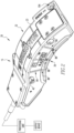
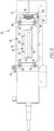
- FIG. 2 is a partially schematic view of an example system 15 for performing non-destructive evaluation of a portion of a pipe in accordance with an example embodiment of the present invention.
- System 15 includes a processing unit 16 in communication with an output device 18 and an apparatus 20 for interacting with a pipe that is being inspected.
- System 15 may also include an input device (not shown) in communication with processing unit 16 for inputting of information to processing unit 16.
- output device 18 may be in the form of a combination input/output device (e.g., without limitation, a touchscreen) for both inputting information to, and receiving information from, processing unit 16.
- Processing unit 16 includes a processing portion which may be, for example, a microprocessor, a microcontroller or some other suitable processing device, and a memory portion that may be internal to the processing portion or operatively coupled to the processing portion and that provides a storage medium for data and software executable by the processing portion for controlling the operation of system 15.
- the memory portion can be any of one or more of a variety of types of internal and/or external storage media such as, without limitation, RAM, ROM, EPROM(s), EEPROM(s), FLASH, and the like that provide a storage register, i.e., a machine readable medium, for data storage such as in the fashion of an internal storage area of a computer, and can be volatile memory or nonvolatile memory.
- Output device 18 may be any suitable device for viewing output from system 15.
- output device 18 may be one or more of: an electronic display screen, a device producing a tangible output (e.g., a printer), or a device which communicates information received from processing unit 16 to one or more other devices (either local or remote) via any suitable communications means.
- Apparatus 20 includes a plurality of ultrasonic sensors 21 ( Figure 5 ), in communication (e.g., via suitable cabling, not numbered) with processing unit 16, which are selectively disposed in a frame assembly 22.
- Frame assembly 22 is utilized to hold ultrasonic sensors 21 a fixed distance from a pipe being inspected while providing for such sensors 21 to be moved along such pipe in a quick, predictable, repeatable fashion, while carrying out a non-destructive evaluation of such pipe.
- the plurality of ultrasonic sensors 21 are in the form of a flexible 64 element (i.e., 64 sensors) phased array probe, such as manufactured by Olympus NDT Division, however, it is to be appreciated that other suitable sensor arrangements may be employed without varying from the scope of the present invention.
- Figure 8 shows a comparison of the scanning area B of such phased array probe versus the scanning area A of a point sensor such as previously described in the Background section.
- Frame assembly 22 includes a frame 23, which is structured to have a number of components disposed therein or thereon, in addition to sensors 21, as will be discussed further below.
- frame 23 was constructed utilizing an additive manufacturing process from an ABS material. Is to be appreciated, however, that frame 23 may be formed via other suitable process and/or material or materials without varying from the scope of the present invention.
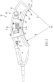
- frame 23 is structured to generally cooperatively engage an outer surface 24 of a pipe P (only a portion of which is shown) which is being evaluated/inspected, and then be slid along (i.e., in a direction parallel to the longitudinal axis A of pipe P) outer surface 24 of pipe P, such as shown by block arrows D 1 and D 2 in Figure 4 , as will be discussed in further detail below.
- apparatus 20 has a generally low profile which generally allows for use in tight spaces.
- frame 23 includes a curved surface 26 which is curved about a longitudinal axis A' which, when frame 23 is generally engaged with pipe P, generally coincides with the central longitudinal axis A of pipe P.
- Curved surface 26 is generally defined by a radius R' which is generally equal to an outer radius R of pipe P.
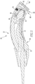
- a main passage 30 is defined in frame 23 between ultrasonic sensors 21 and curved surface 26.
- a skirt 32 formed from a flexible material (e.g., silicone sponge rubber, flexible foam, or other suitable material), extends outward from curved surface 26 and is disposed around and completely encircling the opening (not numbered) of main passage 30 in curved surface 26.
- skirt 32 is disposed partially in a groove 34 ( Figure 7 ) formed in curved surface 26, however, it is to be appreciated that other arrangements of skirt 32 may be employed without varying from the scope of the present invention.
- Main passage 30 and skirt 32 are positioned such that when apparatus 20 is disposed on outer surface 24 of pipe P, such as shown in Figures 3 and 4 , a reservoir 36 is formed which is generally defined on a first side (not numbered) by ultrasonic sensors 21, on a second side (not numbered) opposite the first side by outer surface 24 of pipe P, and by main passage 30 and skirt 32 which extend between such first and second sides.
- reservoir 36 is provided with a supply of a suitable ultrasonic conductive fluid (not shown, e.g., without limitation water) via a number of fluid supply conduits 40 (a portion of one is shown in Figure 7 ) which extend from a main fluid supply inlet 42 positioned on an outer surface (not numbered) of frame 23 to a number of outlets 44 which open into reservoir 36.
- a suitable ultrasonic conductive fluid not shown, e.g., without limitation water
- fluid supply conduits 40 a portion of one is shown in Figure 7
- three outlets 44 defined generally in curved surface 26 within an area bounded by skirt 32 are employed (e.g., see Figure 6 ), however, is to be appreciated that other quantities and/or positioning of the number of outlets 44 may be varied without varying from the scope of the present invention.
- a coating (not numbered) may be provided on a pipe contacting surface 46 of skirt 32.
- a layer of polyethylene tape was employed, however, it is to be appreciated that other suitable material may be employed without varying from the scope of the present invention.
- a number of air removal conduits 50 which extend from one or more inlets 52 in reservoir 36 to one or more outlets 54 defined in an exterior surface of frame 23.
- Such conduits 50 may also be provided with a suitable check valve arrangement which allows for such pathways to selectively be opened or closed as desired by a user of apparatus 20.
- frame assembly 22 further includes an encoder device 58 disposed within a cavity 60 defined in frame 23.
- Encoder device 58 is electrically connected to processing unit 16 via suitable cabling (not numbered).
- encoder device 58 includes an encoder wheel 62 which is rotatable about an encoder axis 64.
- Encoder wheel 62 includes an outer surface 66 which, as shown in Figure 3 , is structured to slightly protrude from frame 23 through an opening or slot 68 defined in frame 23 and engage outer surface 24 of pipe P.
- encoder device 58 may be pivotally mounted to frame 23 and a biasing mechanism, such as a spring 70, or other suitable mechanism, may be provided on or in frame 23 which biases outer surface 66 of encoder wheel 62 generally toward outer surface 24 of pipe P.
- a biasing mechanism such as a spring 70, or other suitable mechanism
- Such biasing mechanism may be adjustably coupled to frame 23 such that the biasing force provided by such mechanism on encoder device 58, and thus to outer surface 66 of encoder wheel 62 thereof, may be selectively adjusted by a user of apparatus 20.
- encoder device 58 may be positioned in other locations with respect to frame 23.
- encoder device 58 may utilize any suitable arrangement for tracking the positioning of frame 23 without varying from the scope of the present invention.
- frame 23 may include a number (four are included in the illustrated example embodiment) of magnetic elements 80 positioned at or about curved surface 26 (e.g., provided on or in recesses formed in curved surface 26).
- magnetic elements 80 e.g., axial ring magnets with poles on the flats ends thereof were employed as magnetic elements 80, however, it is to be appreciated that other suitable magnets or magnetic structures may be employed without varying from the scope of the present invention.
- Each magnetic element 80 may be adjustably coupled to frame 23 via a suitable adjustment mechanism, e.g., without limitation and Alan head screw 82, which allows for the relative positioning of each magnetic element 80 in regard to pipe P to be adjusted and thus the strength of the magnetic attraction between each element 80 and pipe P to be selectively adjusted. It is to be appreciated that the inclusion of such magnetic elements 80 not only ensures consistent engagement between apparatus 20 and outer surface 24 of pipe P but can also provide for apparatus 20 two remain magnetically attached to pipe P thus allowing a technician the use of both hands when needed without losing track of the location of where apparatus 20 was on pipe P.
- a suitable adjustment mechanism e.g., without limitation and Alan head screw 82
- frame 23 may be provided with a number of indicia formed as an integral portion thereof or as an element added thereto.
- frame 23 includes indicia in the form of raised bars 84 which indicate the opposing ends of ultrasonic array 21, as well as a shorter central bar 86 which indicates the center of ultrasonic array 21.
- indicia may also be in the form of alphanumeric characters, such as the numerals 88 which provide indicators of the positioning as well as identifying number of some of the plurality of ultrasonic sensors 21.
- outer surface 24 of pipe P is preferably marked with indicia 100 to indicate the left and right bounds of the area which is to be scanned.
- the positioning of such indicia 100 is determined by dividing the circumference of pipe P into a plurality of spacings equal to the width of the area covered by the plurality of ultrasonic sensors 21.
- apparatus 20 is placed onto outer surface 24 of pipe P, a flow of ultrasonic conducting fluid is provided to main fluid supply inlet 42 (e.g., such as via a suitable pump providing liquid from a reservoir or other supply), and apparatus 20 is then slid on outer surface 24 of pipe P in a direction parallel to the longitudinal axis A of pipe P (such as shown by either of block arrows D 1 or D 2 of Figure 4 ) until a desired length of pipe P has been scanned.
- main fluid supply inlet 42 e.g., such as via a suitable pump providing liquid from a reservoir or other supply
- Part B of Figure 9 shows an partially schematic example of the graphical output 200 (such as provided on output unit 18 of Figure 2 ) of the data (approximately 8000 data points) obtained in one of such passes made by apparatus 20 in a matter of a few seconds.
- each of the different hashes represent different colors (e.g., red, orange, yellow, green, blue, etc.) which correspond to different thicknesses, such as shown in the scale 202.
- a continuous blend of colors (similar to a rainbow, e.g., red transitions to orange which transitions yellow then to green, etc., as opposed to sharp cut-offs) is utilized to better show transitions in thicknesses.
- output 200 thus generally resembles a weather radar map but instead of showing different storm intensities with differing colors different thicknesses are shown.
- Part A of Figure 9 shows data 210 (39 data points) obtained by a method such as described in the Background section of this application for a similar section of pipe which required approximately 45 minutes to obtain. From such comparison, it is to be readily appreciated that the present invention provides quicker results which are of much greater resolution and provide a readily readable result of variations in wall thickness thickness of pipe P.
- frame assembly 22 may include one or more index buttons electrically connected to processing unit 16 which allow for user of apparatus 20 readily indicate the positioning of a subsequent pass after completing a given pass.
- frame assembly 22 includes a left index button 102 and a right index button 104, each being positioned generally near an end of apparatus 20 so as to be readily activated by either a left-hand or a right-hand, respectively, of the user.
- a user upon completing a scanning pass with apparatus 20, a user would activate the appropriate index button to indicate that the next scanning pass they are making is either to the right of the just completed pass (and thus would activate button 104) or to the left of the just completed pass (and thus would activate button 102).
- each of buttons 102 and 104 provide a signal to processing unit 16 which is recognized by processing unit 16 is an indication of the respective column in which data from the scan about to be received is to be placed in the output relative to the data from the previous scan.
- embodiments of the present invention provide for a section of piping to be ultrasonically scanned faster, in greater detail, and with more readily readable results than prior solutions. It is also to be readily appreciated that embodiments of the present invention may be readily utilized in inspecting both straight portions of pipe as well as curved sections. In order to accommodate the intrados of a curved section, the thickness T, such as shown in Figure 4 , may be minimized so as to ensure that skirt 32 does not become disengaged from outer surface 24 of pipe P during a scanning pass. Additionally or alternatively depending on the application, frame 23 may be provided with one or more chamfered sections, such as chamfered sections 110 shown in Figure 7 , which provide for better fitment of frame 23 on the intrados portion of a curved section of pipe.
- the plurality of ultrasonic sensors 21 may readily be removed from a first apparatus 20 having a frame assembly 22 with a frame 23 sized to fit a pipe having a first diameter, and placed into a second apparatus 20 having a frame assembly 22 with a frame 23 which is sized to fit another pipe having a second diameter which is different than the first diameter.
- kit which includes a single sensor array having the plurality of ultrasonic sensors 21 along with a plurality (e.g., without limitation, five) of frame assemblies 22, each having a frame 23 which is sized to fit a different diameter pipe.
- the user of such kit could selectively place the single sensor array in the frame assembly 22 having the frame 23 which is sized to fit the pipe which is to be inspected.
- any reference signs placed between parentheses shall not be construed as limiting the claim.
- the word “comprising” or “including” does not exclude the presence of elements or steps other than those listed in a claim.
- several of these means may be embodied by one and the same item of hardware.
- the word “a” or “an” preceding an element does not exclude the presence of a plurality of such elements.
- any device claim enumerating several means several of these means may be embodied by one and the same item of hardware.
- the mere fact that certain elements are recited in mutually different dependent claims does not indicate that these elements cannot be used in combination.
Landscapes
- Physics & Mathematics (AREA)
- General Physics & Mathematics (AREA)
- Life Sciences & Earth Sciences (AREA)
- Chemical & Material Sciences (AREA)
- Health & Medical Sciences (AREA)
- Analytical Chemistry (AREA)
- Biochemistry (AREA)
- General Health & Medical Sciences (AREA)
- Immunology (AREA)
- Pathology (AREA)
- Acoustics & Sound (AREA)
- Biodiversity & Conservation Biology (AREA)
- Ecology (AREA)
- Environmental & Geological Engineering (AREA)
- Environmental Sciences (AREA)
- Investigating Or Analyzing Materials By The Use Of Ultrasonic Waves (AREA)
Applications Claiming Priority (2)
| Application Number | Priority Date | Filing Date | Title |
|---|---|---|---|
| US201762577834P | 2017-10-27 | 2017-10-27 | |
| PCT/US2018/046602 WO2019083592A1 (en) | 2017-10-27 | 2018-08-14 | APPARATUS AND METHOD FOR ENHANCING DETECTION OF CORROSION SLIMMING |
Publications (3)
| Publication Number | Publication Date |
|---|---|
| EP3701257A1 EP3701257A1 (en) | 2020-09-02 |
| EP3701257A4 EP3701257A4 (en) | 2021-08-11 |
| EP3701257B1 true EP3701257B1 (en) | 2024-03-20 |
Family
ID=66243665
Family Applications (1)
| Application Number | Title | Priority Date | Filing Date |
|---|---|---|---|
| EP18870759.0A Active EP3701257B1 (en) | 2017-10-27 | 2018-08-14 | Apparatus and method for improved corrosion thinning detection |
Country Status (6)
| Country | Link |
|---|---|
| US (1) | US11549916B2 (ko) |
| EP (1) | EP3701257B1 (ko) |
| JP (1) | JP7194182B2 (ko) |
| KR (1) | KR102707495B1 (ko) |
| CN (1) | CN111465847B (ko) |
| WO (1) | WO2019083592A1 (ko) |
Families Citing this family (8)
| Publication number | Priority date | Publication date | Assignee | Title |
|---|---|---|---|---|
| CN111465847B (zh) | 2017-10-27 | 2023-11-24 | 西屋电气有限责任公司 | 用于改善腐蚀减薄检测的装置和方法 |
| US11327052B2 (en) * | 2019-08-28 | 2022-05-10 | The Boeing Company | Ultrasonic inspection probe, system, and method |
| EP4034869A1 (en) * | 2019-09-24 | 2022-08-03 | Quest Integrity Group, LLC | Ultrasound scanner apparatus |
| CA3155955A1 (en) * | 2019-10-25 | 2021-04-29 | Ke Wang | Ultrasonic patch transducer for monitoring the condition of a structural asset |
| EP3816621A1 (de) | 2019-10-30 | 2021-05-05 | Georg Fischer Rohrleitungssysteme AG | Prüfung einer muffenschweissung |
| US11686710B2 (en) | 2020-03-31 | 2023-06-27 | Evident Canada, Inc. | Longitudinal and circumferential ultrasound scanner |
| USD1103806S1 (en) | 2020-10-22 | 2025-12-02 | Evident Canada, Inc. | Scanner frame |
| CN114594161B (zh) * | 2022-03-05 | 2026-02-24 | 浙江永立钢业有限公司 | 一种用于不锈钢钢管的超声波裂纹检测设备 |
Family Cites Families (57)
| Publication number | Priority date | Publication date | Assignee | Title |
|---|---|---|---|---|
| JPS493029Y1 (ko) * | 1968-01-30 | 1974-01-25 | ||
| JPS53102686U (ko) * | 1977-01-24 | 1978-08-18 | ||
| US4543528A (en) * | 1982-09-30 | 1985-09-24 | Republic Steel Corporation | Flexible probe assembly for use in nondestructive testing of a convex workpiece surface |
| JPS61159153A (ja) * | 1984-12-29 | 1986-07-18 | Jgc Corp | 超音波探傷用探触子ホルダ |
| JPS6338157A (ja) * | 1986-08-04 | 1988-02-18 | Power Reactor & Nuclear Fuel Dev Corp | 超音波探触子 |
| US4955235A (en) | 1987-07-30 | 1990-09-11 | Westinghouse Electric Corp. | Apparatus and method for providing a combined ultrasonic and eddy current inspection of a metallic body |
| JPH0375557A (ja) * | 1989-08-18 | 1991-03-29 | Mitsubishi Electric Corp | 超音波探触子 |
| JPH04161848A (ja) * | 1990-10-25 | 1992-06-05 | Mitsubishi Electric Corp | 超音波自動探傷装置 |
| US5313837A (en) * | 1991-09-26 | 1994-05-24 | Ico, Inc. | Ultrasonic thickness gage for pipe |
| US5770800A (en) | 1994-09-27 | 1998-06-23 | The United States Of America As Represented By The United States Department Of Energy | Flexible ultrasonic pipe inspection apparatus |
| WO1996022527A1 (en) * | 1995-01-17 | 1996-07-25 | The Penn State Research Foundation | Bore probe for tube inspection with guided waves and method therefor |
| JP3200026B2 (ja) * | 1997-04-04 | 2001-08-20 | 日本碍子株式会社 | 周設センサ |
| US5915277A (en) * | 1997-06-23 | 1999-06-22 | General Electric Co. | Probe and method for inspecting an object |
| JP2001349845A (ja) * | 2000-06-07 | 2001-12-21 | Tokyo Gas Co Ltd | 管内検査装置 |
| US6578424B1 (en) * | 2000-09-27 | 2003-06-17 | Digital Wave Corporation | Hand-held variable angle membrane (VAM) ultrasonic scanning head for the noninvasive detection of corrosion, MIC and foreign objects in pipes |
| US6813950B2 (en) * | 2002-07-25 | 2004-11-09 | R/D Tech Inc. | Phased array ultrasonic NDT system for tubes and pipes |
| WO2007024001A1 (ja) * | 2005-08-26 | 2007-03-01 | Sumitomo Metal Industries, Ltd. | 超音波探傷方法及び継目無管の製造方法 |
| JPWO2007113907A1 (ja) * | 2006-04-05 | 2009-08-13 | 住友金属工業株式会社 | 超音波探触子、超音波探傷方法及び超音波探傷装置 |
| CA2554906C (en) * | 2006-05-10 | 2008-09-02 | Robert Allan Simmons | Method and apparatus for conveying an ultrasonic sensor about an outer peripheral surface of a tube |
| US7673525B2 (en) * | 2007-01-09 | 2010-03-09 | Schlumberger Technology Corporation | Sensor system for pipe and flow condition monitoring of a pipeline configured for flowing hydrocarbon mixtures |
| US7852073B2 (en) * | 2007-06-25 | 2010-12-14 | Southwest Research Institute | Method and device for long-range torsional guided-wave inspection of piping with a partial excitation and detection around the pipe circumference |
| US20090178465A1 (en) * | 2008-01-14 | 2009-07-16 | Ethridge Roger E | Acoustic transducer support frame and method |
| JP5083821B2 (ja) * | 2008-02-07 | 2012-11-28 | 株式会社竹中工務店 | 超音波センサ付きの検査装置を用いた導管の腐食状態の検査方法及び腐食状態の検査方法の適用に適した導管の構造 |
| JP2009276085A (ja) | 2008-05-12 | 2009-11-26 | Nikko Kensa Service Kk | 曲面に追随する超音波探傷装置 |
| US8590383B2 (en) * | 2008-06-24 | 2013-11-26 | Alstom Technology Ltd | Ultrasonic inspection probe carrier system for performing non-destructive testing |
| US7913562B2 (en) | 2008-08-29 | 2011-03-29 | Southwest Research Institute | Flexible plate magnetostrictive sensor probe for guided-wave inspection of structures |
| KR20100067539A (ko) * | 2008-12-11 | 2010-06-21 | 엘아이지에이디피 주식회사 | 기판 검사장치 제어방법 |
| US8087298B1 (en) * | 2009-03-10 | 2012-01-03 | Sandia Corporation | Ultrasonic probe deployment device for increased wave transmission and rapid area scan inspections |
| US8166823B2 (en) * | 2009-09-29 | 2012-05-01 | National Oilwell Varco, L.P. | Membrane-coupled ultrasonic probe system for detecting flaws in a tubular |
| US8196472B2 (en) * | 2009-09-29 | 2012-06-12 | National Oilwell Varco, L.P. | Ultrasonic probe apparatus, system, and method for detecting flaws in a tubular |
| GB201018259D0 (en) | 2010-10-29 | 2010-12-15 | Airbus Operations Ltd | Ultrasonic inspection tool |
| JP5737992B2 (ja) * | 2011-02-18 | 2015-06-17 | 三菱重工業株式会社 | 超音波探傷装置 |
| US9063059B2 (en) | 2011-05-10 | 2015-06-23 | Edison Welding Institute, Inc. | Three-dimensional matrix phased array spot weld inspection system |
| JP5406881B2 (ja) | 2011-05-19 | 2014-02-05 | 日立Geニュークリア・エナジー株式会社 | 耐熱超音波センサ及びその設置方法 |
| CN105549016B (zh) | 2011-09-26 | 2018-11-02 | 安大略发电有限公司 | 超声矩阵检验 |
| JP5649599B2 (ja) | 2012-02-27 | 2015-01-07 | 三菱重工業株式会社 | 超音波検査装置及びその検査方法 |
| GB201214273D0 (en) | 2012-08-09 | 2012-09-26 | Airbus Uk Ltd | .Improvements to radius inspection tools |
| US9995716B2 (en) * | 2012-10-12 | 2018-06-12 | General Electric Technology Gmbh | Method for determining boiler tube cold side cracking and article for accomplishing the same |
| US9404896B2 (en) * | 2012-11-19 | 2016-08-02 | General Electric Company | Two-dimensional TR probe array |
| US9335302B2 (en) | 2012-12-06 | 2016-05-10 | General Electric Company | Probe approach for DGS sizing |
| WO2014098068A1 (ja) | 2012-12-18 | 2014-06-26 | 株式会社移動ロボット研究所 | 配管検査ロボット、及び配管の検査方法 |
| US20140352438A1 (en) | 2013-05-28 | 2014-12-04 | General Electric Company | Device for ultrasonic inspection |
| WO2015081135A1 (en) * | 2013-11-30 | 2015-06-04 | Saudi Arabian Oil Company | Modular mobile inspection vehicle |
| WO2015089667A1 (en) | 2013-12-17 | 2015-06-25 | Ontario Power Generation Inc. | Improved ultrasound inspection |
| US10557828B2 (en) | 2014-02-17 | 2020-02-11 | Westinghouse Electric Company Llc | Ultrasonic phased array transducer for the NDE inspection of the jet pump riser welds and welded attachments |
| US10732131B2 (en) * | 2014-03-13 | 2020-08-04 | General Electric Company | Curved digital X-ray detector for weld inspection |
| WO2016053048A1 (ko) | 2014-10-02 | 2016-04-07 | 삼성전자 주식회사 | 초음파 탐촉자용 어태치먼트, 초음파 탐촉자, 초음파 검사 장치 및 초음파 검사 방법 |
| DE102014119684A1 (de) * | 2014-12-29 | 2016-06-30 | Areva Gmbh | Vorrichtung und ein Verfahren zur zerstörungsfreien Prüfung eines Bauteils mit Ultraschall |
| US10119942B2 (en) * | 2015-02-13 | 2018-11-06 | Fbs, Inc. | Medium-range magnetostrictive ultrasonic guided wave scanner systems and methods |
| CN104792871A (zh) | 2015-04-15 | 2015-07-22 | 烟台富润实业有限公司 | 便携式管道螺旋焊缝柔性相控阵超声波无损检测设备 |
| WO2016203486A1 (en) | 2015-06-17 | 2016-12-22 | Acousticeye Ltd | Adjustable wide bandwidth guidedwave (gw) probe for tube and pipe inspection system |
| CN105548370B (zh) * | 2016-01-29 | 2018-07-06 | 安徽理工大学 | 一种可探测曲面工件的超声相控阵探头 |
| US10241083B2 (en) | 2016-03-11 | 2019-03-26 | General Electric Company | Ultrasonic inspection probe assembly |
| EP3236255A1 (en) * | 2016-04-21 | 2017-10-25 | NEM Energy B.V. | Apparatus and method for observing a butt-welded portion of a tube |
| US10564131B2 (en) | 2016-05-23 | 2020-02-18 | Olympus Scientific Solutions Americas Inc. | Water wedge for flexible probe |
| US11225961B2 (en) * | 2017-02-21 | 2022-01-18 | Sensus Spectrum, Llc | Multi-element bending transducers and related methods and devices |
| CN111465847B (zh) | 2017-10-27 | 2023-11-24 | 西屋电气有限责任公司 | 用于改善腐蚀减薄检测的装置和方法 |
-
2018
- 2018-08-14 CN CN201880079624.3A patent/CN111465847B/zh active Active
- 2018-08-14 US US16/102,928 patent/US11549916B2/en active Active
- 2018-08-14 JP JP2020523754A patent/JP7194182B2/ja active Active
- 2018-08-14 WO PCT/US2018/046602 patent/WO2019083592A1/en not_active Ceased
- 2018-08-14 EP EP18870759.0A patent/EP3701257B1/en active Active
- 2018-08-14 KR KR1020207014524A patent/KR102707495B1/ko active Active
Also Published As
| Publication number | Publication date |
|---|---|
| BR112020008355A2 (pt) | 2020-11-03 |
| US20190128850A1 (en) | 2019-05-02 |
| CN111465847B (zh) | 2023-11-24 |
| EP3701257A1 (en) | 2020-09-02 |
| US11549916B2 (en) | 2023-01-10 |
| JP2021501320A (ja) | 2021-01-14 |
| EP3701257A4 (en) | 2021-08-11 |
| JP7194182B2 (ja) | 2022-12-21 |
| CN111465847A (zh) | 2020-07-28 |
| KR102707495B1 (ko) | 2024-09-19 |
| WO2019083592A1 (en) | 2019-05-02 |
| KR20200089265A (ko) | 2020-07-24 |
Similar Documents
| Publication | Publication Date | Title |
|---|---|---|
| EP3701257B1 (en) | Apparatus and method for improved corrosion thinning detection | |
| CN105467000B (zh) | 埋地管道管体缺陷非开挖检测方法及装置 | |
| JP6114778B2 (ja) | ボイラー管の低温側クラッキングを決定する方法およびその方法を達成するための装置 | |
| CN101680592B (zh) | 内部检测组件和在待检测管内定中检测探测器的方法 | |
| US5767410A (en) | Lamb wave ultrasonic probe for crack detection and measurement in thin-walled tubing | |
| US20190383784A1 (en) | Pipeline inspection assembly using synthetic weld flaws | |
| US10048225B2 (en) | Apparatus and method for inspection of tubes in a boiler | |
| GB2494170A (en) | Acoustic pipeline inspection | |
| US11162919B2 (en) | Ultrasonic based internal inspection of tubes | |
| US20240209975A1 (en) | Method And Tool For Inspecting The Condition Of The Internal Surface Of Pipes | |
| US12399155B2 (en) | Device for inspecting a pipe, in particular with regard to clandestine tapping | |
| NO772624L (no) | Anordning for kontrollering av korrosjon av en beholders innervegg | |
| BR112020008355B1 (pt) | Sistema e método para realizar avaliação ultrassônica | |
| Oliveira et al. | Making available high resolution UT technology for subsea wall thickness scans | |
| Zhang et al. | Advanced Inspection Techniques for Submarine Pipeline Integrity | |
| Hennig et al. | EVO series 1.0-latest generation of UT crack and corrosion tools for high speed pipeline inspection | |
| OA21295A (en) | Device for inspecting a pipe, in particular with regard to clandestine tapping. | |
| Syuhada et al. | Sound Signal Potential for Visualization of Corrosion in Pipelines | |
| BR102023005233A2 (pt) | Método rotativo para inspeção de alta resolução de dutos | |
| BR102022026427A2 (pt) | Método e ferramenta de inspeção da condição da superfície interna de dutos | |
| Lu et al. | Pipeline Inspection and Health Monitoring Technology | |
| Methods et al. | CORROSION TESTING AND MEASUREMENT: A LOOK AT SOME NEW INSTRUMENTS AND EQUIPMENT | |
| Nirmale et al. | A Review on Underwater Inspection of steel liner welds in hazardous environment | |
| Schmidt et al. | Development of Microwave Interferometry Nondestructive Testing Solution for Complex Materials |
Legal Events
| Date | Code | Title | Description |
|---|---|---|---|
| STAA | Information on the status of an ep patent application or granted ep patent |
Free format text: STATUS: THE INTERNATIONAL PUBLICATION HAS BEEN MADE |
|
| PUAI | Public reference made under article 153(3) epc to a published international application that has entered the european phase |
Free format text: ORIGINAL CODE: 0009012 |
|
| STAA | Information on the status of an ep patent application or granted ep patent |
Free format text: STATUS: REQUEST FOR EXAMINATION WAS MADE |
|
| 17P | Request for examination filed |
Effective date: 20200513 |
|
| AK | Designated contracting states |
Kind code of ref document: A1 Designated state(s): AL AT BE BG CH CY CZ DE DK EE ES FI FR GB GR HR HU IE IS IT LI LT LU LV MC MK MT NL NO PL PT RO RS SE SI SK SM TR |
|
| AX | Request for extension of the european patent |
Extension state: BA ME |
|
| DAV | Request for validation of the european patent (deleted) | ||
| DAX | Request for extension of the european patent (deleted) | ||
| A4 | Supplementary search report drawn up and despatched |
Effective date: 20210709 |
|
| RIC1 | Information provided on ipc code assigned before grant |
Ipc: G01N 29/265 20060101AFI20210705BHEP Ipc: G01N 29/04 20060101ALI20210705BHEP Ipc: G01B 17/02 20060101ALI20210705BHEP Ipc: G01N 29/26 20060101ALI20210705BHEP |
|
| GRAP | Despatch of communication of intention to grant a patent |
Free format text: ORIGINAL CODE: EPIDOSNIGR1 |
|
| STAA | Information on the status of an ep patent application or granted ep patent |
Free format text: STATUS: GRANT OF PATENT IS INTENDED |
|
| INTG | Intention to grant announced |
Effective date: 20231023 |
|
| P01 | Opt-out of the competence of the unified patent court (upc) registered |
Effective date: 20231113 |
|
| GRAS | Grant fee paid |
Free format text: ORIGINAL CODE: EPIDOSNIGR3 |
|
| GRAA | (expected) grant |
Free format text: ORIGINAL CODE: 0009210 |
|
| STAA | Information on the status of an ep patent application or granted ep patent |
Free format text: STATUS: THE PATENT HAS BEEN GRANTED |
|
| AK | Designated contracting states |
Kind code of ref document: B1 Designated state(s): AL AT BE BG CH CY CZ DE DK EE ES FI FR GB GR HR HU IE IS IT LI LT LU LV MC MK MT NL NO PL PT RO RS SE SI SK SM TR |
|
| REG | Reference to a national code |
Ref country code: GB Ref legal event code: FG4D |
|
| REG | Reference to a national code |
Ref country code: CH Ref legal event code: EP |
|
| REG | Reference to a national code |
Ref country code: IE Ref legal event code: FG4D |
|
| REG | Reference to a national code |
Ref country code: DE Ref legal event code: R096 Ref document number: 602018066990 Country of ref document: DE |
|
| REG | Reference to a national code |
Ref country code: SE Ref legal event code: TRGR |
|
| PG25 | Lapsed in a contracting state [announced via postgrant information from national office to epo] |
Ref country code: LT Free format text: LAPSE BECAUSE OF FAILURE TO SUBMIT A TRANSLATION OF THE DESCRIPTION OR TO PAY THE FEE WITHIN THE PRESCRIBED TIME-LIMIT Effective date: 20240320 |
|
| REG | Reference to a national code |
Ref country code: LT Ref legal event code: MG9D |
|
| PG25 | Lapsed in a contracting state [announced via postgrant information from national office to epo] |
Ref country code: GR Free format text: LAPSE BECAUSE OF FAILURE TO SUBMIT A TRANSLATION OF THE DESCRIPTION OR TO PAY THE FEE WITHIN THE PRESCRIBED TIME-LIMIT Effective date: 20240621 |
|
| PG25 | Lapsed in a contracting state [announced via postgrant information from national office to epo] |
Ref country code: HR Free format text: LAPSE BECAUSE OF FAILURE TO SUBMIT A TRANSLATION OF THE DESCRIPTION OR TO PAY THE FEE WITHIN THE PRESCRIBED TIME-LIMIT Effective date: 20240320 Ref country code: RS Free format text: LAPSE BECAUSE OF FAILURE TO SUBMIT A TRANSLATION OF THE DESCRIPTION OR TO PAY THE FEE WITHIN THE PRESCRIBED TIME-LIMIT Effective date: 20240620 |
|
| REG | Reference to a national code |
Ref country code: NL Ref legal event code: MP Effective date: 20240320 |
|
| PG25 | Lapsed in a contracting state [announced via postgrant information from national office to epo] |
Ref country code: RS Free format text: LAPSE BECAUSE OF FAILURE TO SUBMIT A TRANSLATION OF THE DESCRIPTION OR TO PAY THE FEE WITHIN THE PRESCRIBED TIME-LIMIT Effective date: 20240620 Ref country code: NO Free format text: LAPSE BECAUSE OF FAILURE TO SUBMIT A TRANSLATION OF THE DESCRIPTION OR TO PAY THE FEE WITHIN THE PRESCRIBED TIME-LIMIT Effective date: 20240620 Ref country code: LT Free format text: LAPSE BECAUSE OF FAILURE TO SUBMIT A TRANSLATION OF THE DESCRIPTION OR TO PAY THE FEE WITHIN THE PRESCRIBED TIME-LIMIT Effective date: 20240320 Ref country code: HR Free format text: LAPSE BECAUSE OF FAILURE TO SUBMIT A TRANSLATION OF THE DESCRIPTION OR TO PAY THE FEE WITHIN THE PRESCRIBED TIME-LIMIT Effective date: 20240320 Ref country code: GR Free format text: LAPSE BECAUSE OF FAILURE TO SUBMIT A TRANSLATION OF THE DESCRIPTION OR TO PAY THE FEE WITHIN THE PRESCRIBED TIME-LIMIT Effective date: 20240621 Ref country code: FI Free format text: LAPSE BECAUSE OF FAILURE TO SUBMIT A TRANSLATION OF THE DESCRIPTION OR TO PAY THE FEE WITHIN THE PRESCRIBED TIME-LIMIT Effective date: 20240320 Ref country code: BG Free format text: LAPSE BECAUSE OF FAILURE TO SUBMIT A TRANSLATION OF THE DESCRIPTION OR TO PAY THE FEE WITHIN THE PRESCRIBED TIME-LIMIT Effective date: 20240320 |
|
| REG | Reference to a national code |
Ref country code: AT Ref legal event code: MK05 Ref document number: 1668249 Country of ref document: AT Kind code of ref document: T Effective date: 20240320 |
|
| PG25 | Lapsed in a contracting state [announced via postgrant information from national office to epo] |
Ref country code: LV Free format text: LAPSE BECAUSE OF FAILURE TO SUBMIT A TRANSLATION OF THE DESCRIPTION OR TO PAY THE FEE WITHIN THE PRESCRIBED TIME-LIMIT Effective date: 20240320 |
|
| PG25 | Lapsed in a contracting state [announced via postgrant information from national office to epo] |
Ref country code: NL Free format text: LAPSE BECAUSE OF FAILURE TO SUBMIT A TRANSLATION OF THE DESCRIPTION OR TO PAY THE FEE WITHIN THE PRESCRIBED TIME-LIMIT Effective date: 20240320 |
|
| PG25 | Lapsed in a contracting state [announced via postgrant information from national office to epo] |
Ref country code: NL Free format text: LAPSE BECAUSE OF FAILURE TO SUBMIT A TRANSLATION OF THE DESCRIPTION OR TO PAY THE FEE WITHIN THE PRESCRIBED TIME-LIMIT Effective date: 20240320 |
|
| PG25 | Lapsed in a contracting state [announced via postgrant information from national office to epo] |
Ref country code: IS Free format text: LAPSE BECAUSE OF FAILURE TO SUBMIT A TRANSLATION OF THE DESCRIPTION OR TO PAY THE FEE WITHIN THE PRESCRIBED TIME-LIMIT Effective date: 20240720 |
|
| PG25 | Lapsed in a contracting state [announced via postgrant information from national office to epo] |
Ref country code: SM Free format text: LAPSE BECAUSE OF FAILURE TO SUBMIT A TRANSLATION OF THE DESCRIPTION OR TO PAY THE FEE WITHIN THE PRESCRIBED TIME-LIMIT Effective date: 20240320 Ref country code: PT Free format text: LAPSE BECAUSE OF FAILURE TO SUBMIT A TRANSLATION OF THE DESCRIPTION OR TO PAY THE FEE WITHIN THE PRESCRIBED TIME-LIMIT Effective date: 20240722 |
|
| PG25 | Lapsed in a contracting state [announced via postgrant information from national office to epo] |
Ref country code: ES Free format text: LAPSE BECAUSE OF FAILURE TO SUBMIT A TRANSLATION OF THE DESCRIPTION OR TO PAY THE FEE WITHIN THE PRESCRIBED TIME-LIMIT Effective date: 20240320 |
|
| PG25 | Lapsed in a contracting state [announced via postgrant information from national office to epo] |
Ref country code: EE Free format text: LAPSE BECAUSE OF FAILURE TO SUBMIT A TRANSLATION OF THE DESCRIPTION OR TO PAY THE FEE WITHIN THE PRESCRIBED TIME-LIMIT Effective date: 20240320 |
|
| PG25 | Lapsed in a contracting state [announced via postgrant information from national office to epo] |
Ref country code: AT Free format text: LAPSE BECAUSE OF FAILURE TO SUBMIT A TRANSLATION OF THE DESCRIPTION OR TO PAY THE FEE WITHIN THE PRESCRIBED TIME-LIMIT Effective date: 20240320 |
|
| PG25 | Lapsed in a contracting state [announced via postgrant information from national office to epo] |
Ref country code: PL Free format text: LAPSE BECAUSE OF FAILURE TO SUBMIT A TRANSLATION OF THE DESCRIPTION OR TO PAY THE FEE WITHIN THE PRESCRIBED TIME-LIMIT Effective date: 20240320 |
|
| PG25 | Lapsed in a contracting state [announced via postgrant information from national office to epo] |
Ref country code: SK Free format text: LAPSE BECAUSE OF FAILURE TO SUBMIT A TRANSLATION OF THE DESCRIPTION OR TO PAY THE FEE WITHIN THE PRESCRIBED TIME-LIMIT Effective date: 20240320 |
|
| PG25 | Lapsed in a contracting state [announced via postgrant information from national office to epo] |
Ref country code: SM Free format text: LAPSE BECAUSE OF FAILURE TO SUBMIT A TRANSLATION OF THE DESCRIPTION OR TO PAY THE FEE WITHIN THE PRESCRIBED TIME-LIMIT Effective date: 20240320 Ref country code: SK Free format text: LAPSE BECAUSE OF FAILURE TO SUBMIT A TRANSLATION OF THE DESCRIPTION OR TO PAY THE FEE WITHIN THE PRESCRIBED TIME-LIMIT Effective date: 20240320 Ref country code: RO Free format text: LAPSE BECAUSE OF FAILURE TO SUBMIT A TRANSLATION OF THE DESCRIPTION OR TO PAY THE FEE WITHIN THE PRESCRIBED TIME-LIMIT Effective date: 20240320 Ref country code: PT Free format text: LAPSE BECAUSE OF FAILURE TO SUBMIT A TRANSLATION OF THE DESCRIPTION OR TO PAY THE FEE WITHIN THE PRESCRIBED TIME-LIMIT Effective date: 20240722 Ref country code: PL Free format text: LAPSE BECAUSE OF FAILURE TO SUBMIT A TRANSLATION OF THE DESCRIPTION OR TO PAY THE FEE WITHIN THE PRESCRIBED TIME-LIMIT Effective date: 20240320 Ref country code: IS Free format text: LAPSE BECAUSE OF FAILURE TO SUBMIT A TRANSLATION OF THE DESCRIPTION OR TO PAY THE FEE WITHIN THE PRESCRIBED TIME-LIMIT Effective date: 20240720 Ref country code: ES Free format text: LAPSE BECAUSE OF FAILURE TO SUBMIT A TRANSLATION OF THE DESCRIPTION OR TO PAY THE FEE WITHIN THE PRESCRIBED TIME-LIMIT Effective date: 20240320 Ref country code: EE Free format text: LAPSE BECAUSE OF FAILURE TO SUBMIT A TRANSLATION OF THE DESCRIPTION OR TO PAY THE FEE WITHIN THE PRESCRIBED TIME-LIMIT Effective date: 20240320 Ref country code: AT Free format text: LAPSE BECAUSE OF FAILURE TO SUBMIT A TRANSLATION OF THE DESCRIPTION OR TO PAY THE FEE WITHIN THE PRESCRIBED TIME-LIMIT Effective date: 20240320 |
|
| PG25 | Lapsed in a contracting state [announced via postgrant information from national office to epo] |
Ref country code: IT Free format text: LAPSE BECAUSE OF FAILURE TO SUBMIT A TRANSLATION OF THE DESCRIPTION OR TO PAY THE FEE WITHIN THE PRESCRIBED TIME-LIMIT Effective date: 20240320 |
|
| REG | Reference to a national code |
Ref country code: DE Ref legal event code: R097 Ref document number: 602018066990 Country of ref document: DE |
|
| PG25 | Lapsed in a contracting state [announced via postgrant information from national office to epo] |
Ref country code: IT Free format text: LAPSE BECAUSE OF FAILURE TO SUBMIT A TRANSLATION OF THE DESCRIPTION OR TO PAY THE FEE WITHIN THE PRESCRIBED TIME-LIMIT Effective date: 20240320 |
|
| PG25 | Lapsed in a contracting state [announced via postgrant information from national office to epo] |
Ref country code: DK Free format text: LAPSE BECAUSE OF FAILURE TO SUBMIT A TRANSLATION OF THE DESCRIPTION OR TO PAY THE FEE WITHIN THE PRESCRIBED TIME-LIMIT Effective date: 20240320 |
|
| PLBE | No opposition filed within time limit |
Free format text: ORIGINAL CODE: 0009261 |
|
| STAA | Information on the status of an ep patent application or granted ep patent |
Free format text: STATUS: NO OPPOSITION FILED WITHIN TIME LIMIT |
|
| PG25 | Lapsed in a contracting state [announced via postgrant information from national office to epo] |
Ref country code: DK Free format text: LAPSE BECAUSE OF FAILURE TO SUBMIT A TRANSLATION OF THE DESCRIPTION OR TO PAY THE FEE WITHIN THE PRESCRIBED TIME-LIMIT Effective date: 20240320 |
|
| 26N | No opposition filed |
Effective date: 20241223 |
|
| REG | Reference to a national code |
Ref country code: DE Ref legal event code: R119 Ref document number: 602018066990 Country of ref document: DE |
|
| PG25 | Lapsed in a contracting state [announced via postgrant information from national office to epo] |
Ref country code: LU Free format text: LAPSE BECAUSE OF NON-PAYMENT OF DUE FEES Effective date: 20240814 |
|
| PG25 | Lapsed in a contracting state [announced via postgrant information from national office to epo] |
Ref country code: SI Free format text: LAPSE BECAUSE OF FAILURE TO SUBMIT A TRANSLATION OF THE DESCRIPTION OR TO PAY THE FEE WITHIN THE PRESCRIBED TIME-LIMIT Effective date: 20240320 Ref country code: MC Free format text: LAPSE BECAUSE OF FAILURE TO SUBMIT A TRANSLATION OF THE DESCRIPTION OR TO PAY THE FEE WITHIN THE PRESCRIBED TIME-LIMIT Effective date: 20240320 |
|
| PG25 | Lapsed in a contracting state [announced via postgrant information from national office to epo] |
Ref country code: DE Free format text: LAPSE BECAUSE OF NON-PAYMENT OF DUE FEES Effective date: 20250301 |
|
| PG25 | Lapsed in a contracting state [announced via postgrant information from national office to epo] |
Ref country code: IE Free format text: LAPSE BECAUSE OF NON-PAYMENT OF DUE FEES Effective date: 20240814 |
|
| PGFP | Annual fee paid to national office [announced via postgrant information from national office to epo] |
Ref country code: BE Payment date: 20250819 Year of fee payment: 8 Ref country code: GB Payment date: 20250821 Year of fee payment: 8 |
|
| PGFP | Annual fee paid to national office [announced via postgrant information from national office to epo] |
Ref country code: FR Payment date: 20250818 Year of fee payment: 8 |
|
| PGFP | Annual fee paid to national office [announced via postgrant information from national office to epo] |
Ref country code: CH Payment date: 20250901 Year of fee payment: 8 Ref country code: SE Payment date: 20250812 Year of fee payment: 8 |
|
| PGFP | Annual fee paid to national office [announced via postgrant information from national office to epo] |
Ref country code: CZ Payment date: 20250725 Year of fee payment: 8 |
|
| PG25 | Lapsed in a contracting state [announced via postgrant information from national office to epo] |
Ref country code: CY Free format text: LAPSE BECAUSE OF FAILURE TO SUBMIT A TRANSLATION OF THE DESCRIPTION OR TO PAY THE FEE WITHIN THE PRESCRIBED TIME-LIMIT; INVALID AB INITIO Effective date: 20180814 |
|
| PG25 | Lapsed in a contracting state [announced via postgrant information from national office to epo] |
Ref country code: HU Free format text: LAPSE BECAUSE OF FAILURE TO SUBMIT A TRANSLATION OF THE DESCRIPTION OR TO PAY THE FEE WITHIN THE PRESCRIBED TIME-LIMIT; INVALID AB INITIO Effective date: 20180814 |