EP3701407B1 - Procédé d'authentification biométrique utilisant une pluralité de caméras avec différents champs de vision et appareil électronique associé - Google Patents
Procédé d'authentification biométrique utilisant une pluralité de caméras avec différents champs de vision et appareil électronique associé Download PDFInfo
- Publication number
- EP3701407B1 EP3701407B1 EP19756969.2A EP19756969A EP3701407B1 EP 3701407 B1 EP3701407 B1 EP 3701407B1 EP 19756969 A EP19756969 A EP 19756969A EP 3701407 B1 EP3701407 B1 EP 3701407B1
- Authority
- EP
- European Patent Office
- Prior art keywords
- electronic apparatus
- image
- authentication
- external object
- camera
- Prior art date
- Legal status (The legal status is an assumption and is not a legal conclusion. Google has not performed a legal analysis and makes no representation as to the accuracy of the status listed.)
- Active
Links
Images







Classifications
-
- G—PHYSICS
- G06—COMPUTING OR CALCULATING; COUNTING
- G06F—ELECTRIC DIGITAL DATA PROCESSING
- G06F21/00—Security arrangements for protecting computers, components thereof, programs or data against unauthorised activity
- G06F21/30—Authentication, i.e. establishing the identity or authorisation of security principals
- G06F21/31—User authentication
- G06F21/32—User authentication using biometric data, e.g. fingerprints, iris scans or voiceprints
-
- G—PHYSICS
- G06—COMPUTING OR CALCULATING; COUNTING
- G06F—ELECTRIC DIGITAL DATA PROCESSING
- G06F21/00—Security arrangements for protecting computers, components thereof, programs or data against unauthorised activity
- G06F21/30—Authentication, i.e. establishing the identity or authorisation of security principals
- G06F21/45—Structures or tools for the administration of authentication
-
- G—PHYSICS
- G06—COMPUTING OR CALCULATING; COUNTING
- G06V—IMAGE OR VIDEO RECOGNITION OR UNDERSTANDING
- G06V10/00—Arrangements for image or video recognition or understanding
- G06V10/10—Image acquisition
- G06V10/12—Details of acquisition arrangements; Constructional details thereof
- G06V10/14—Optical characteristics of the device performing the acquisition or on the illumination arrangements
- G06V10/147—Details of sensors, e.g. sensor lenses
-
- G—PHYSICS
- G06—COMPUTING OR CALCULATING; COUNTING
- G06V—IMAGE OR VIDEO RECOGNITION OR UNDERSTANDING
- G06V40/00—Recognition of biometric, human-related or animal-related patterns in image or video data
- G06V40/10—Human or animal bodies, e.g. vehicle occupants or pedestrians; Body parts, e.g. hands
- G06V40/16—Human faces, e.g. facial parts, sketches or expressions
- G06V40/161—Detection; Localisation; Normalisation
- G06V40/165—Detection; Localisation; Normalisation using facial parts and geometric relationships
-
- G—PHYSICS
- G06—COMPUTING OR CALCULATING; COUNTING
- G06V—IMAGE OR VIDEO RECOGNITION OR UNDERSTANDING
- G06V40/00—Recognition of biometric, human-related or animal-related patterns in image or video data
- G06V40/10—Human or animal bodies, e.g. vehicle occupants or pedestrians; Body parts, e.g. hands
- G06V40/16—Human faces, e.g. facial parts, sketches or expressions
- G06V40/161—Detection; Localisation; Normalisation
- G06V40/166—Detection; Localisation; Normalisation using acquisition arrangements
-
- G—PHYSICS
- G06—COMPUTING OR CALCULATING; COUNTING
- G06V—IMAGE OR VIDEO RECOGNITION OR UNDERSTANDING
- G06V40/00—Recognition of biometric, human-related or animal-related patterns in image or video data
- G06V40/10—Human or animal bodies, e.g. vehicle occupants or pedestrians; Body parts, e.g. hands
- G06V40/18—Eye characteristics, e.g. of the iris
- G06V40/19—Sensors therefor
-
- G—PHYSICS
- G06—COMPUTING OR CALCULATING; COUNTING
- G06V—IMAGE OR VIDEO RECOGNITION OR UNDERSTANDING
- G06V40/00—Recognition of biometric, human-related or animal-related patterns in image or video data
- G06V40/60—Static or dynamic means for assisting the user to position a body part for biometric acquisition
- G06V40/67—Static or dynamic means for assisting the user to position a body part for biometric acquisition by interactive indications to the user
-
- G—PHYSICS
- G06—COMPUTING OR CALCULATING; COUNTING
- G06V—IMAGE OR VIDEO RECOGNITION OR UNDERSTANDING
- G06V40/00—Recognition of biometric, human-related or animal-related patterns in image or video data
- G06V40/70—Multimodal biometrics, e.g. combining information from different biometric modalities
-
- H—ELECTRICITY
- H04—ELECTRIC COMMUNICATION TECHNIQUE
- H04N—PICTORIAL COMMUNICATION, e.g. TELEVISION
- H04N23/00—Cameras or camera modules comprising electronic image sensors; Control thereof
- H04N23/45—Cameras or camera modules comprising electronic image sensors; Control thereof for generating image signals from two or more image sensors being of different type or operating in different modes, e.g. with a CMOS sensor for moving images in combination with a charge-coupled device [CCD] for still images
-
- H—ELECTRICITY
- H04—ELECTRIC COMMUNICATION TECHNIQUE
- H04N—PICTORIAL COMMUNICATION, e.g. TELEVISION
- H04N23/00—Cameras or camera modules comprising electronic image sensors; Control thereof
- H04N23/60—Control of cameras or camera modules
- H04N23/61—Control of cameras or camera modules based on recognised objects
- H04N23/611—Control of cameras or camera modules based on recognised objects where the recognised objects include parts of the human body
-
- H—ELECTRICITY
- H04—ELECTRIC COMMUNICATION TECHNIQUE
- H04N—PICTORIAL COMMUNICATION, e.g. TELEVISION
- H04N23/00—Cameras or camera modules comprising electronic image sensors; Control thereof
- H04N23/60—Control of cameras or camera modules
- H04N23/64—Computer-aided capture of images, e.g. transfer from script file into camera, check of taken image quality, advice or proposal for image composition or decision on when to take image
-
- H—ELECTRICITY
- H04—ELECTRIC COMMUNICATION TECHNIQUE
- H04N—PICTORIAL COMMUNICATION, e.g. TELEVISION
- H04N23/00—Cameras or camera modules comprising electronic image sensors; Control thereof
- H04N23/90—Arrangement of cameras or camera modules, e.g. multiple cameras in TV studios or sports stadiums
Definitions
- the present disclosure relates to an authentication technology using biometric information.
- biometric authentication is an authentication method that extracts biometric information, which is specified to a person, such as fingerprints, an iris, a sweat gland structure, a face, blood vessels, or the like to use the extracted biometric information.
- the biometric authentication is being used for various purposes in electronic apparatuses.
- the biometric authentication is applied to various fields such as unlocking of a home screen for the use of an electronic apparatus and user authentication upon making an electronic commerce payment.
- US2017061210A1 discloses an infrared lamp control for use with iris recognition authentication.
- US2018008161A1 discloses a method for recognizing an iris based on user intention and an electronic device for the same.
- US2016364561A1 discloses a mobile terminal and a method for controlling the same.
- the electronic apparatus may recognize an object associated with biometric authentication to obtain biometric information.
- recognition of the object which is the target of authentication, may be performed before the authentication.
- the biometric authentication may be influenced by an external environment (e.g., user movement, or the like) while capturing an object, and thus the research for recognizing the appropriate object is actively underway.
- various functions described below can be implemented or supported by one or more computer programs, each of which is formed from computer readable program code and embodied in a computer readable medium.
- application and “program” refer to one or more computer programs, software components, sets of instructions, procedures, functions, objects, classes, instances, related data, or a portion thereof adapted for implementation in a suitable computer readable program code.
- computer readable program code includes any type of computer code, including source code, object code, and executable code.
- computer readable medium includes any type of medium capable of being accessed by a computer, such as read only memory (ROM), random access memory (RAM), a hard disk drive, a compact disc (CD), a digital video disc (DVD), or any other type of memory.
- ROM read only memory
- RAM random access memory
- CD compact disc
- DVD digital video disc
- a "non-transitory” computer readable medium excludes wired, wireless, optical, or other communication links that transport transitory electrical or other signals.
- a non-transitory computer readable medium includes media where data can be permanently stored and media where data can be stored and later overwritten, such as a rewritable optical disc or an erasable memory device.
- an electronic apparatus may improve user convenience by providing the feedback associated with the state of a specified object.
- an electronic apparatus may efficiently perform biometric authentication by adaptively using a plurality of authentication methods.
- FIGS. 1 through 21 discussed below, and the various embodiments used to describe the principles of the present disclosure in this patent document are by way of illustration only and should not be construed in any way to limit the scope of the disclosure. Those skilled in the art will understand that the principles of the present disclosure may be implemented in any suitably arranged system or device.
- FIG. 1 illustrates an operating environment of an electronic apparatus, according to an embodiment.
- an electronic apparatus 100 performs biometric authentication.
- the electronic apparatus 100 obtains a request associated with biometric authentication, obtains an image including at least one external object in response to the request, recognizes or obtains an external object associated with the biometric authentication among at least one external object, and perform the biometric authentication by using biometric information corresponding to the external object.
- the external object associated with the biometric authentication is the object predetermined depending on the authentication method.
- the external object associated with the biometric authentication is referred to as a specified object.
- the at least one external object may include, for example, various external objects surrounding the user of the electronic apparatus 100 (or a body part of the user) or the user.
- the specified object may be set in advance.
- the specified object may be an iris and/or a face depending on user settings. While the authentication method of the electronic apparatus is set to iris authentication, the specified object may be an iris.
- the authentication method may be an adaptive authentication method.
- the adaptive authentication method may be an authentication method that makes it possible to selectively apply the authentication mode depending on the state of the electronic apparatus 100 or the external object.
- the electronic apparatus 100 includes a plurality of cameras 120 and 122 to obtain an external object.
- the plurality of cameras 120 and 122 obtain images corresponding to field of views different each other.
- the first camera 120 has a first field of view (hereinafter referred to as "FOV") (or angle of view) and the second camera 122 has a second FOV.
- the first FOV includes the second FOV.
- the first FOV includes a range wider than the second FOV.
- the plurality of cameras 120 and 122 are disposed on one surface 111 of the electronic apparatus.
- a display 140 may be disposed on the one surface 111.
- FIG. 2 illustrates a block diagram a configuration of an electronic apparatus, according to an embodiment.
- the electronic apparatus 100 (e.g., the electronic apparatus 100 of FIG. 1 ) includes a processor 110, the first camera 120, and the second camera 122.
- the configuration of the electronic apparatus 100 may be variously changed or modified according to various embodiments of the present disclosure.
- the electronic apparatus 100 may further include a component such as a memory (e.g., the memory 2132 of FIG. 21 ), a display (e.g., the display device 2160 of FIG. 21 ), or a communication device (e.g., the communication module 2190 of FIG. 21 ).
- the processor 110 performs an operation according to various embodiments of the present disclosure or controls the operation of another component.
- the processor 110 commands an operation of another component or receives a command from another component.
- the processor 110 obtains at least one image through the first camera 120 or the second camera 122 and processes the obtained image.
- the processor 110 obtains the specified object from the obtained image.
- the processor 110 performs user authentication using the specified object.
- the user authentication includes biometric authentication.
- the biometric authentication includes iris authentication or face authentication.
- the processor 110 allows the first camera 120 or the second camera 122 to capture an external object, to display the obtained image on a display, and/or to store information in a memory or to read out the stored information.
- the processor 110 may include at least one of an image processing processor, an application processor, or a camera driving device.
- the operation of the electronic apparatus according to the embodiments disclosed below may be performed by at least one processor.
- the first camera 120 captures an external object of the electronic apparatus 100.
- the processor 110 allows the first camera 120 to capture the external object.
- the processor 110 obtains a first image corresponding to a first FOV through the first camera 120 and including at least one external object.
- the first camera 120 is disposed on the front surface or the rear surface of the electronic apparatus 100.
- the first camera 120 is exposed through the front housing or the rear housing of the electronic apparatus 100.
- the second camera 122 captures an external object of the electronic apparatus 100.
- the processor 110 allows the second camera 122 to capture the external object.
- the processor 110 obtains a second image corresponding to a second FOV through the second camera 122 and including at least one external object.
- the second camera 122 is disposed on the front surface or the rear surface of the electronic apparatus 100.
- the second camera 122 is exposed through the front housing or the rear housing of the electronic apparatus 100.
- the first camera 120 may be a device configured to obtain an image using visible light.
- the first camera 120 includes an image sensor such as a complementary metal oxide semiconductor (CMOS) or charge-couple device sensor (CCD).
- CMOS complementary metal oxide semiconductor
- CCD charge-couple device sensor
- the first image may mean an image obtained through the first camera 120.
- the first image is a raw image and may include information about the intensity of light sensed by the imaging medium.
- the first image may be a full resolution image sensed by the first camera 120.
- the second camera 122 may be a device configured to obtain an image using an infrared ray (IR).
- the second camera 122 may include at least one of an IR image sensor or a band pass filter.
- the IR image sensor may sense the image being captured and may convert the image into an electrical signal.
- the second camera 122 may obtain an image corresponding to the biometric authentication based on the IR image sensor.
- the second image may mean an image obtained through the second camera 122.
- the image is a raw image and may have information about the intensity of light sensed by the imaging medium.
- the image may be a full resolution image sensed by the IR image sensor.
- the second camera 122 may be referred to as an "IR camera", and the image captured by the second camera 122 may be referred to as an "IR image”.
- the electronic apparatus 100 may include a memory (not illustrated).
- the memory may store various pieces of information described in the present disclosure.
- the memory may store settings associated with the authentication of the electronic apparatus 100.
- the electronic apparatus 100 may be configured to perform iris authentication and/or face authentication in response to a request associated with the authentication.
- the memory may store images obtained through the first camera 120 and/or the second camera 122.
- the image may be stored in the form of an image file or a video file.
- the memory may store information associated with the authentication.
- the memory may digitalize and/or encrypt the biometric information biometric information associated with a user of the electronic apparatus 100 to store the encrypted biometric information in advance.
- the stored biometric information may be referred to as "biometric data" for performing user authentication.
- the memory may store biometric feature information authenticated for biometric recognition.
- the biometric data or biometric feature information may be stored in the secure area of the memory.
- the memory may be the memory included in a secure element.
- the secure element may include a secure digital (SD) card.
- the memory may store instructions that direct the various operations described herein.
- the processor 110 may execute the instructions.
- the display (not illustrated) of the electronic apparatus 100 may display various pieces of information (e.g., multimedia data or text data) to a user.
- the display may display a screen according to the control of the processor 110.
- the display may be a touchscreen display for obtaining a user input.
- the processor 110 may display a screen including a preview image on the display, or a screen including a graphic image.
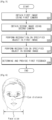
- FIG. 3 illustrates a view for conceptually describing an operation in which an electronic apparatus recognizes a specified object by using two or more cameras.
- an electronic apparatus may primarily identify specified objects 321, 322, and 323 within a first image 301 obtained through a first camera (e.g., the first camera 120 of FIG. 2 ) and may secondarily identify specified objects 321, 322, and 323 within a second image 302.
- At least one first external object in the first FOV of the first camera may be included in the first image 301
- at least one second external object in the second FOV of the second camera may be included in the second image 302.
- the first image 301 corresponds to the first FOV.
- the second image 302 corresponds to the second FOV.
- the electronic apparatus 100 obtains the at least one first image 301 through the first camera and obtains the at least one second image 302 through the second camera.
- the electronic apparatus may identify whether the specified objects 321, 322, and 323 are present in the second image 302.
- the electronic apparatus may identify whether the specified object 323 is present in the second image 302 or may try to recognize the specified object 323. Referring to FIG. 3 , since the specified object 323 is not positioned in the second image 302, the electronic apparatus may fail to recognize the specified object 323.
- the electronic apparatus may identify whether the specified object 322 is present in the second image 302 or may try to recognize the specified object 322. Referring to FIG. 3 , since the specified object 322 is included in the second image 302, the electronic apparatus may successfully recognize the specified object 322.
- the electronic apparatus may identify whether the specified objects 321, 322, and 323 obtained using the first image 301 and the second image 302 are appropriate. When the specified objects 321, 322, and 323 satisfy the conditions for biometric authentication, the electronic apparatus may determine that the specified objects 321, 322, and 323 are appropriate. For example, the electronic apparatus may identify whether the specified objects 321, 322, and 323 are appropriate, based on the distance between the specified objects 321, 322, and 323 and the electronic apparatus and/or the locations of the specified objects 321, 322, and 323. For example, when the distance from the electronic apparatus to each of the specified objects 321, 322, and 323 is too far or too close, the electronic apparatus may determine that the specified objects 321, 322, and 323 are not appropriate.
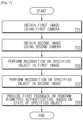
- FIG. 4 illustrates a flowchart of an operation in which an electronic apparatus recognizes a specified object by using two or more cameras, according to an example that provides context to the present invention.
- an electronic apparatus may perform first recognition using the first image 301 and may perform second recognition using the second image 302.
- the electronic apparatus may provide a feedback to a user based on at least the result of performing the second recognition.
- the operation of the electronic apparatus described below may be performed by a processor (e.g., the processor 110 of FIG. 2 ) of the electronic apparatus.
- the following operations may be stored in the memory of the electronic apparatus in the form of instructions.
- the electronic apparatus may perform second recognition, using the second image obtained through the second camera.
- the electronic apparatus may obtain the second image corresponding to the second FOV through the second camera.
- the second image may include at least one second external object.
- the electronic apparatus may perform the second recognition operation using the second image.
- the electronic apparatus may try to recognize the specified object in the second image.
- the electronic apparatus may provide a feedback based on at least content from performing the second recognition.
- the electronic apparatus may provide a feedback based on the first recognition content and the second recognition content.
- FIG. 5 illustrates an operational flowchart of an electronic apparatus providing a first feedback, according to an example that provides context to the present invention.
- an electronic apparatus may recognize the specified object in a first image; when the electronic apparatus fails to recognize the specified object in the second image, the electronic apparatus may provide a user with the first feedback.
- the first feedback may include notification information that allows an electronic apparatus to obtain at least one second image including the specified object.
- the notification information may include information associated with a location.
- the notification information may be associated with an external object. For example, the notification information may be associated with the external object obtained in the first image.
- the operation of the electronic apparatus described below may be performed by a processor (e.g., the processor 110 of FIG. 2 ) of the electronic apparatus (e.g., the electronic apparatus 100 of FIG. 1 ).
- the following operations may be stored in the memory of the electronic apparatus in the form of instructions.
- the electronic apparatus may obtain the first image using the first camera.
- the first image may include at least one first external object.
- the at least one first external object may be positioned in the first FOV of the first camera.
- the specified object may be included in at least part of at least one first external object.
- the electronic apparatus may obtain the second image by using the second camera.
- the second image may include at least one second external object.
- the second external object may be positioned in the second FOV of the second camera. According to the example provided in FIG. 5 , the at least one second external object may not include the specified object.
- the electronic apparatus may perform recognition on the specified object in the first image.
- the electronic apparatus may identify the specified object while obtaining the first image. Since it is assumed that the specified object is included in the first image in operation 501, the electronic apparatus may recognize or detect the specified object in the first image.
- the electronic apparatus may perform recognition on the specified object in the second image.
- the electronic apparatus may identify the specified object while obtaining the second image. Since it is assumed that the specified object is not included in the second image in operation 503, the electronic apparatus may fail to recognize (or detect) the specified object in the second image.
- the specified object in operation 507 may be different from the specified object in operation 505. For example, in operation 507, the specified object may be a part of the specified object according to operation 505.
- the electronic apparatus may determine the first feedback and may provide the first feedback.
- the electronic apparatus may determine the first feedback based on the distance to the specified object and/or location of the specified object, in response to an operation of identifying the specified object in the second image.
- the electronic apparatus may provide the determined first feedback.
- the electronic apparatus may provide the first feedback to a user through various methods. For example, the electronic apparatus may display the first feedback via a display, or may provide the first feedback to the user via voice and/or vibration.
- the first feedback may include notification information that allows the electronic apparatus to obtain at least one second image including the specified object. Even though the specified object is not included in the second image, the notification information may be provided to the user by identifying the specified object through the first camera.
- the notification information may include notification information associated with a location.
- the electronic apparatus may identify that the external object is not located at the specified location (e.g., within the second FOV range) and may provide the first feedback including notification information associated with the location.
- FIG. 6 illustrates a view for conceptually describing a method of providing a first feedback, according to an example that provides context to the present invention.
- an electronic apparatus may provide the first feedback to obtain at least one second image including the external object.
- the first feedback may include notification information associated with a distance and/or a location.
- the notification information associated with the distance and/or location may be information for notifying a user that the external object is located within the specified distance range from the electronic apparatus.
- the electronic apparatus may obtain the distance from an external object or a specified object to the electronic apparatus.
- the specified object is an iris (or eye)
- the electronic apparatus may obtain the distance from the external object or specified object to the electronic apparatus based on the eye distance or the detected face size.
- the electronic apparatus may provide the first feedback to the user.
- the electronic apparatus may provide the user with a first feedback including notification information associated with the distance and/or location based on at least second recognition content.
- the first feedback may be provided to the user based on the first recognition content and the second recognition content.
- the electronic apparatus may provide the first feedback.
- the specified object is not appropriate, for example, when the electronic apparatus does not satisfy the condition associated with the distance, the electronic apparatus may determine that the specified object is not appropriate. For example, when the distance between the specified object and the electronic apparatus is out of the specified distance range, the electronic apparatus may determine that the specified object is not appropriate.
- FIG. 7 illustrates an operational flowchart of an electronic apparatus providing a first feedback not forming part of the claimed invention and is included for background only.
- the electronic apparatus may provide a user with a first feedback including notification information associated with a distance and/or location, if necessary.
- the electronic apparatus may provide the first feedback to the user.
- the first feedback may include notification information associated with the distance.
- the operation of the electronic apparatus described below may be performed by a processor (e.g., the processor 110 of FIG. 2 ) of the electronic apparatus. The following operations may be stored in the memory of the electronic apparatus in the form of instructions.
- the electronic apparatus may obtain the first image using the first camera.
- the first image may include at least one first external object.
- the at least one first external object may be positioned in the first FOV of the first camera.
- a specified object may be included in at least part of at least one first external object or may not be included in at least part of at least one first external object.
- the electronic apparatus may obtain the second image including the specified object by using the second camera.
- the second image may include at least one second external object.
- the second external object may be positioned in the second FOV of the second camera.
- the electronic apparatus may perform recognition on the specified object in the first image.
- the electronic apparatus may identify the specified object while obtaining the first image.
- the electronic apparatus may recognize (or detect) the specified object in the first image; when the specified object is not included in the first image, the electronic apparatus may fail to recognize (or detect) the specified object in the first image.
- the electronic apparatus may perform recognition on the specified object in the second image.
- the electronic apparatus may identify the specified object while obtaining the second image. Since it is assumed that the specified object is included in the second image in operation 703, the electronic apparatus may recognize (or detect) the specified object in the second image.
- the specified object in operation 707 may be different from the specified object in operation 705.
- the specified object may be a part of the specified object according to operation 705.
- the electronic apparatus may provide the first feedback or perform biometric authentication, based on the state of the specified object.
- the electronic apparatus may determine the state of the specified object, in response to an operation of identifying the specified object in the second image. For example, the electronic apparatus may determine the distance between the specified object and the electronic apparatus.
- the electronic apparatus may perform the measurement associated with the specified object.
- the electronic apparatus may identify whether the measurement result satisfies the specified distance range.
- the electronic apparatus may identify whether the measurement result is too far away (or longer than or equal to a specified first distance) from the specified object or is too close or equal (or closer than a specified second distance) to the specified object.
- the first feedback may include notification information associated with the distance and/or location of the external object.
- the electronic apparatus may provide the first feedback.
- the electronic apparatus may perform biometric authentication.
- the electronic apparatus may determine that the specified object is appropriate.
- the electronic apparatus may provide the first feedback.
- the electronic apparatus may perform biometric authentication.
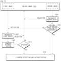
- FIG. 8 illustrates a flowchart of an operation in which an electronic apparatus provides various feedbacks, according to an embodiment.
- an electronic apparatus provides various feedbacks based on the first recognition result and the second recognition result.
- the operations of the electronic apparatus described below are performed by a processor (e.g., the processor 110 of FIG. 2 ) of the electronic apparatus (e.g., the electronic apparatus 100 of FIG. 1 ).
- the following operations may be stored in the memory of the electronic apparatus in the form of instructions.
- the electronic apparatus obtains a request associated with biometric authentication.
- the request associated with the biometric authentication corresponds to the user's selection, a request associated with authentication from the external device, or an operation associated with authentication of the electronic apparatus or is generated in response to the corresponding operation.
- the electronic apparatus obtains a first image and a second image.
- the first image is an image, which is obtained by the electronic apparatus using the first camera.
- the second image is an image, which is obtained by the electronic apparatus using the second camera.
- the electronic apparatus tries to recognize a specified object in the first image.
- the electronic apparatus identifies (or searches for) whether the specified object is present in the first image and tries to recognize the specified object in the second image in operation 807 and operation 817.
- the electronic apparatus may recognize the specified object from the first image in operation 805; when the electronic apparatus does not recognize the specified object from the second image in operation 807, the electronic apparatus performs operation 809; when the electronic apparatus recognizes the specified object from the second image in operation 807 and operation 817, the electronic apparatus performs operation 811.
- operation 805 and operation 817 when the electronic apparatus fails to recognize the specified object from the first image but recognizes the specified object from the second image, the electronic apparatus performs operation 819.
- the specified object to be recognized within the first image is different from the specified object to be recognized within the second image.
- the electronic apparatus tries to recognize the first specified object within the first image and tries to recognize the second specified object within the second image.
- the second specified object includes at least part of the first specified object.
- the electronic apparatus tries to recognize a face including an eyeball within the first image and may tries to recognize the eyeball within the second image.
- the electronic apparatus provides a first feedback.
- the electronic apparatus provides the first feedback including notification information that makes it possible to obtain at least one second image including the specified object, in response to recognition failure of the specified object from the second image.
- the first feedback may be displayed via the display of the electronic apparatus.
- the electronic apparatus determines the first feedback based on the at least second image to provide the first feedback. For example, electronic apparatus identifies whether the specified object satisfies the specified condition, using the first image and the second image. When the specified object does not satisfy the specified condition, the electronic apparatus provides information associated with the distance and/or location based on the distance and/or location of the specified object.
- the electronic apparatus When the specified object associated with the first image is different, the electronic apparatus provides information associated with the distance and/or location based on the distance from at least one specified object and/or the location of at least one specified object among the first specified object or the second specified object.
- the first feedback includes information associated with the distance and/or the location.
- the electronic apparatus provides a first feedback that allows the specified object to be located within the second image, such as movement upward/movement downward/movement to the left/movement to the right.
- the electronic apparatus identifies whether the specified object satisfies a specified condition.
- the specified condition is associated with the distance between the specified object and the electronic apparatus.
- the specified condition includes whether the distance between the specified object and the electronic apparatus satisfies a specified distance range. For example, when the specified object satisfies the specified condition, the electronic apparatus performs the operation 813; when the specified object does not satisfy the specified condition, the electronic apparatus performs operation 809.
- the electronic apparatus may determine whether a specified object (or a specified object to be recognized within a second image) satisfies a specified condition.
- the electronic apparatus provides a first feedback.
- the electronic apparatus provides the first feedback including notification information associated with the distance and/or location, in response to the result of identifying the specified condition.
- the electronic apparatus performs biometric authentication using biometric information corresponding to at least part of the specified object. For example, when the specified object is an eye or a face, the electronic apparatus performs biometric authentication using biometric information corresponding to an iris. The electronic apparatus obtains biometric information from the specified object; and the electronic apparatus performs biometric authentication by comparing the biometric information with biometric data.
- the electronic apparatus may provide a second feedback.
- the second feedback may include the biometric authentication result.
- the electronic apparatus may provide the second feedback indicating an authentication failure; when the biometric information coincides with the biometric data, the electronic apparatus may provide the second feedback indicating an authentication success.
- the authentication success may be indirectly recognized by the user, as an operation of disabling security. For example, when authentication is successful, the electronic apparatus may unlock the home screen lock or may unlock the application lock.
- the electronic apparatus may provide a third feedback.
- the third feedback may include the notification information that allows the specified object to be located within the FOV range.
- the electronic apparatus may perform operation 821.
- the electronic apparatus may determine whether the predetermined time has expired.
- the predetermined time may be the time set for authentication.
- the electronic apparatus may perform operation 803 and then may obtain the next image.
- the electronic apparatus may terminate biometric authentication.
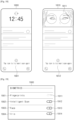
- FIG. 9 illustrates a feedback displayed by the electronic apparatus through a display, according to an example that provides context to the present invention.
- (1) and (2) of FIG. 9 illustrates that an electronic apparatus (e.g., the electronic apparatus 100 of FIG. 1 ) displays a feedback through a display (e.g., the display 140 of FIG. 2 ), and ( 3 ) of FIG. 9 illustrates a screen including the feedback.
- an electronic apparatus e.g., the electronic apparatus 100 of FIG. 1
- displays a feedback through a display e.g., the display 140 of FIG. 2
- ( 3 ) of FIG. 9 illustrates a screen including the feedback.
- the feedback provided by the electronic apparatus may be provided in an image or text format.
- the information included in the feedback may be stored in advance in the memory of the electronic apparatus.
- FIG. 9 illustrates the first feedback including notification information associated with an external object.
- the electronic apparatus may display a screen 900, which includes a first feedback 901 of image form and/or a first feedback 902 of text form, on a display.
- the screen 900 is a home screen, but the electronic apparatus may provide the feedback in an application execution screen.
- the screen 900 may display an item 903 for performing various functions in addition to the feedback described in the present disclosure.
- the item 903 may be an item associated with an application capable of being executed without authentication.
- FIG. 10 illustrates a screen including various feedbacks provided by an electronic apparatus, according to an example that provides context to the present invention.
- a first screen 1000 is illustrated as including a second feedback 1001; a second screen 1010 is illustrated as including a first feedback 1011; and a third screen 1020 is illustrated as including a third feedback 1021.
- the first feedback 1011 is illustrated as including notification information associated with the position of an external object.
- each of the first to third screens 1000 to 1020 is an application execution screen, but the first to third feedbacks 1011, 1001, and 1021 may be displayed on various screens.
- the first to third feedbacks 1001 to 1021 may be displayed on a home screen.
- the first to third feedbacks 1011, 1001, and 1021 may be displayed in a pop-up form on the first to third screens 1000 to 1020.
- the first to third feedbacks 1011, 1001, and 1021 may be included in a separate screen displayed on the first to third screens 1000 to 1020, respectively.
- An electronic apparatus may obtain different specified objects from an image obtained by using a first camera (e.g., the first camera 120 of FIG. 2 ) and a second camera (e.g., the second camera 122 of FIG. 2 ) and may perform two or more pieces of biometric authentication by using the specified objects.
- a first camera e.g., the first camera 120 of FIG. 2
- a second camera e.g., the second camera 122 of FIG. 2
- Various authentication modes for performing two or more pieces of biometric authentication may be defined in the electronic apparatus.
- the electronic apparatus may adaptively select the authentication mode depending on the extent to which security is required.
- FIG. 11 illustrates a flowchart of an operation in which an electronic apparatus adaptively selects an authentication mode, the operation not forming part of the claimed invention and is included for illustration purposes only.
- an electronic apparatus may obtain a security level (or a running operation), may obtain an authentication mode based on the security level (or a running operation), and may perform biometric authentication by using the obtained authentication mode
- the operation of the electronic apparatus described below may be performed by a processor (e.g., the processor 110 of FIG. 2 ) of the electronic apparatus (e.g., the electronic apparatus 100 of FIG. 1 ).
- the following operations may be stored in the memory of the electronic apparatus in the form of instructions.
- the electronic apparatus may obtain a request associated with biometric authentication.
- Operation 1101 may refer to the description of operation 801 in FIG. 8 .
- the electronic apparatus may obtain the security level.
- the security level may be associated with the running operation or the running application in the electronic apparatus.
- the security level according to the operation being executed may be specified.
- the information associated with the security level may be stored in the electronic apparatus in advance. For example, the relationship between the security level and the application may be stored in the electronic apparatus.
- the security level When the electronic apparatus is executing an application associated with a payment, the security level may be the first security level; and when the electronic apparatus is executing the home screen, the security level may be the second security level.
- the second security level may be lower than the first security level.
- the electronic apparatus may obtain the authentication mode based on the security level.
- the electronic apparatus may obtain the first authentication mode for the first security level and may obtain the second authentication mode for the second security level.
- the electronic apparatus may determine the first authentication mode; when the operation being executed is the second operation, the electronic apparatus may determine the second authentication mode. For example, when the electronic apparatus is executing a home screen, the electronic apparatus may determine the first authentication mode; when the electronic apparatus is executing an application associated with a payment, the electronic apparatus may determine the second authentication mode.
- the electronic apparatus may perform an authentication method according to an authentication mode.
- the authentication method may be different depending on the authentication mode. For example, the authentication method of the low security is applied to the first security level requiring relatively low security; a strict authentication method is applied to the second security level requiring relatively high security.
- FIG. 12 conceptually illustrates an authentication method executed by an electronic apparatus, the authentication method not forming part of the claimed invention and is included for illustration purposes only.
- an electronic apparatus may perform two or more pieces of authentication having external objects associated with different biometric authentication methods.
- the operation of the electronic apparatus described below may be performed by a processor (e.g., the processor 110 of FIG. 2 ) of the electronic apparatus (e.g., the electronic apparatus 100 of FIG. 1 ).
- the following operations may be stored in the memory of the electronic apparatus in the form of instructions.
- the electronic apparatus may perform primary authentication based on the external object associated with the first biometric authentication method.
- the first biometric authentication method may be iris authentication.
- the electronic apparatus may perform secondary authentication based on the external object associated with the second biometric authentication method.
- the second biometric authentication method may be face authentication.
- the operation 1203 may be performed based on the first authentication result.
- operation 1203 may be performed when the primary authentication fails.
- the electronic apparatus may perform complex authentication (or tertiary authentication).
- the electronic apparatus may perform complex authentication based on both the first specified object and the second specified object.
- FIG. 13 illustrates a flowchart of an authentication operation of an electronic apparatus, the authentication operation not forming part of the claimed invention and is included for illustration purposes only.
- the primary authentication or the secondary authentication of FIG. 12 may include an operation of performing object recognition and performing object authentication by using the recognized object.
- the operation of the electronic apparatus described below may be performed by a processor (e.g., the processor 110 of FIG. 2 ) of the electronic apparatus (e.g., the electronic apparatus 100 of FIG. 1 ).
- the following operations may be stored in the memory of the electronic apparatus in the form of instructions.
- the electronic apparatus may obtain an image.
- the image may include a first image obtained using a first camera and/or a second image obtained using a second camera.
- the electronic apparatus may perform object recognition.
- the electronic apparatus may search for a specified object within the obtained image.
- the specified object may be an iris in the case of iris authentication and a face in the case of face authentication.
- the electronic apparatus may perform object authentication.
- the electronic apparatus may obtain biometric information corresponding to the specified object and may perform biometric authentication by using the biometric information.
- first object recognition and first object authentication may correspond to an authentication method (e.g., face authentication) requiring a relatively low security
- second object recognition and second object authentication may correspond to an authentication method (e.g., iris authentication) requiring a relatively high security
- the target of the first object recognition and the first object authentication may be the first specified object
- the target of the second object recognition and the second object authentication may be the second specified object.
- the electronic apparatus may set an authentication mode depending on the security level and may execute at least one of the first to third pieces of authentication depending on the corresponding authentication mode.
- the operation of an electronic apparatus for each authentication mode will be described.
- the objects of the primary authentication and the secondary authentication may be different depending on the authentication mode.
- the primary authentication may secure the convenience of a user but may use a face authentication method of low security, and the secondary authentication may use the an iris authentication method of high security.
- the secondary authentication may use the face authentication method.
- FIG. 14 illustrates an operation of an electronic apparatus in a first authentication mode not forming part of the claimed invention and is included for illustration purposes only.
- an electronic apparatus may perform primary to tertiary pieces of authentication depending on the first authentication mode.
- the first authentication mode may be an authentication mode applied when relatively low security is required.
- the first authentication mode may be an authentication mode applied while a home screen is executed.
- the electronic apparatus when the electronic apparatus fails in the primary authentication after performing the primary authentication using a first image obtained by using a first camera (e.g., the first camera 120 of FIG. 2 ), the electronic apparatus may perform the secondary authentication by using a second image obtained by using a second camera (e.g., the second camera 122 of FIG. 2 ).
- the first specified object that is a target of the primary authentication may be a face.
- the second specified object that is a target of the secondary authentication may be an iris.
- the electronic apparatus may perform complex authentication, using the first specified object and the second specified object.
- the electronic apparatus may obtain an image including a first image and a second image.
- Each of the first image and the second image may include at least one external object.
- the first image may be an image obtained by using a first camera
- the second image may be an image obtained by using a second camera.
- the electronic apparatus may perform first object recognition, using the first image.
- the electronic apparatus may search for the first specified object in operation 1403.
- the electronic apparatus may activate secondary authentication.
- the electronic apparatus may determine that the first object recognition fails.
- the electronic apparatus may perform operation 1405.
- the electronic apparatus may perform first object authentication and may identify whether the first object authentication is successful. When the first object authentication fails, the electronic apparatus may activate secondary authentication. When the first object authentication is successful, the electronic apparatus may perform operation 1415.
- the electronic apparatus may activate the secondary authentication.
- the case where the primary authentication fails may include the case where first object recognition fails or the case where first object authentication fails.
- the electronic apparatus may perform second object recognition.
- the electronic apparatus may identify whether the second image includes the second specified object.
- the electronic apparatus may perform operation 1401.
- the electronic apparatus may obtain the following image.
- the electronic apparatus may perform operation 1409.
- the electronic apparatus may determine whether the second object authentication is successful.
- the electronic apparatus may perform the second object authentication in response to the second object recognition.
- the electronic apparatus may identify whether the second specified object coincides with the previously stored biometric data.
- the electronic apparatus may perform operation 1415; when the second object authentication fails, the electronic apparatus may perform operation 1411.
- the electronic apparatus may perform complex authentication.
- the electronic apparatus may perform authentication, using the first specified object and the second specified object.
- the electronic apparatus may identify whether the complex authentication is successful. When the complex authentication fails, the electronic apparatus may perform operation 1401; when complex authentication is successful, the electronic apparatus may perform operation 1415.
- the electronic apparatus may perform liveness detection and authentication.
- the electronic apparatus may perform authentication based on the result of liveness detection.
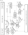
- FIG. 15 illustrates a flowchart of an operation of an electronic apparatus in a second authentication mode not forming a part of the claimed invention and is included for illustration purposes only.
- an electronic apparatus may perform primary to tertiary pieces of authentication depending on the second authentication mode.
- the second authentication mode may be an authentication mode applied when relatively high security is required.
- the electronic apparatus may perform the secondary authentication by using a first image obtained by using a first camera (e.g., the first camera 120 of FIG. 2 ).
- the first specified object that is a target of the primary authentication may be an iris.
- the second specified object that is a target of the secondary authentication may be a face.
- the electronic apparatus may perform complex authentication, using the first specified object and the second specified object.
- the electronic apparatus may obtain an image.
- the electronic apparatus may obtain a first image and a second image from the image.
- the electronic apparatus may perform second object recognition. Operation 1503 may be the same as or similar to operation 1407 of FIG. 14 .
- the electronic apparatus may determine whether the second object authentication is successful. Operation 1505 may be the same as or similar to operation 1409 of FIG. 14 . When the second object authentication is successful, the electronic apparatus may perform operation 1513. When the second object authentication fails, the electronic apparatus may activate secondary authentication.
- the electronic apparatus may perform first object recognition. Operation 1507 may be the same as or similar to operation 1403 of FIG. 14 .
- the electronic apparatus may obtain operation 1501 and then may obtain the next image.
- the electronic apparatus may perform operation 1509.
- the electronic apparatus may perform complex authentication.
- the electronic apparatus may perform authentication, using the first specified object and the second specified object.
- the electronic apparatus may determine whether the complex authentication is successful. When the complex authentication is successful, the electronic apparatus may perform operation 1513. When the complex authentication fails, the electronic apparatus may obtain the next image in operation 1501 and then, may retry authentication.
- the electronic apparatus may perform liveness detection and authentication.
- FIG. 16 illustrates a flowchart of an operation of an electronic apparatus in a first authentication mode not forming a part of the claimed invention and is included for illustration purposes only.
- an electronic apparatus may determine the authentication criteria when performing complex authentication.
- authentication may be flexibility performed on the first authentication mode requiring a lower security level and the second authentication mode requiring a higher security level.
- the operation of the electronic apparatus described below may be performed by a processor of the electronic apparatus.
- the following operations may be stored in the memory of the electronic apparatus in the form of instructions.
- the electronic apparatus may obtain an image and may preferentially perform primary authentication using a first image.
- the electronic apparatus may perform the primary authentication; when the primary authentication fails, the electronic apparatus may perform operation 1619 and operation 1621.
- Operation 1603 may be the same as or similar to operation 1403 of FIG. 14 ;
- operation 1607 may be the same as or similar to operation 1405 of FIG. 14 ;
- operation 1619 may be the same as or similar to operation 1407 of FIG. 14 ;
- operation 1621 may be the same as or similar to operation 1409 of FIG. 14 .
- the detailed description will be omitted.
- the electronic apparatus may identify the state (or the state of a specified object) of the electronic apparatus.
- the electronic apparatus may obtain the next image; when the state of the electronic apparatus is not the specified state, the electronic apparatus may activate the secondary authentication and may perform operation 1607.
- FIG. 16 for better understanding, the case of determining whether the state of the electronic apparatus is a low illumination (LI) state is illustrated.
- LI state the electronic apparatus may activate the secondary authentication and may perform operation 1619.
- the electronic apparatus may perform operation 1601 and may obtain the next image.
- the electronic apparatus may perform secondary authentication as auxiliary authentication.
- the electronic apparatus may perform operation 1623; when the first object authentication fails, the electronic apparatus may perform operation 1609.
- the electronic apparatus may identify whether the first image includes the second specified object.
- the electronic apparatus may identify whether the first image includes the object associated with the secondary authentication.
- the electronic apparatus may perform operation 1611; when the first image includes the second specified object, the electronic apparatus may activate secondary authentication and may perform operation 1613.
- the electronic apparatus may prevent the secondary authentication from being performed unnecessarily.
- the electronic apparatus may transmit a message to the user.
- the message may be a message indicating that authentication fails.
- the electronic apparatus may determine the authentication criteria.
- the authentication criteria may be authentication criteria associated with complex authentication.
- the authentication criteria may be associated with a false accept rate (FAR).
- the electronic apparatus may determine the FAR associated with the first object recognition (e.g., face recognition) as authentication criteria in the first authentication mode; the electronic apparatus may determine the FAR associated with second object recognition (e.g., iris recognition) as the authentication criteria in the second authentication mode.
- first object recognition e.g., face recognition
- second object recognition e.g., iris recognition
- the electronic apparatus may perform complex authentication in operation 1615; the electronic apparatus may apply the authentication criteria determined in operation 1613.
- the electronic apparatus may perform complex authentication, using the first specified object and the second specified object.
- the electronic apparatus may apply the FAR associated with the first object recognition depending on the operation 1613 while performing complex authentication.
- the electronic apparatus may determine whether the complex authentication is successful; when the complex authentication is successful, the electronic apparatus may perform liveness detection and authentication in operation 1623. When complex authentication fails in operation 1617, the electronic apparatus may perform operation 1601 and then may obtain the next image.
- the electronic apparatus may perform face authentication in primary authentication, may determine whether to perform secondary authentication depending on an external environment when applying a relatively low security mode for performing iris authentication in secondary authentication, and may perform user authentication using secondary authentication and/or complex authentication when primary authentication is not successful due to the bad external environment.
- the electronic apparatus may authenticate the user by using iris authentication.
- the electronic apparatus when the electronic apparatus is in the LI environment, the obtained face image may be too dark or too noisy. In this case, when the reliability of authentication is not enough because there is not enough face features capable of being obtained within the first image, the electronic apparatus may authenticate the user via iris authentication.
- efficient authentication may be performed by supplementing the disadvantages of first authentication with second authentication and considering the state of the electronic apparatus.
- FIG. 17 illustrates a flowchart of an operation of an electronic apparatus in a second authentication mode not forming a part of the claimed invention and is included for illustration purposes only.
- the electronic apparatus may determine whether to perform the secondary authentication, based on the state (or, situation) of an external object. For example, the electronic apparatus may determine whether to perform the secondary authentication, in consideration of a situation where the user is wearing glasses or is placed outdoors.
- the operation of the electronic apparatus e.g., the electronic apparatus 100 of FIG. 1
- the operation of the electronic apparatus may be performed by a processor (e.g., the processor 110 of FIG. 2 ) of the electronic apparatus.
- the following operations may be stored in the memory of the electronic apparatus in the form of instructions.
- the electronic apparatus may obtain an image.
- the electronic apparatus may preferentially perform primary authentication using a second image.
- the electronic apparatus may identify the state of the external object (or the electronic apparatus) and may perform secondary authentication using a first image in operation 1709 based on the state of the external object.
- Operation 1703 may be the same as or similar to operation 1503 of FIG. 15 ;
- operation 1705 may be the same as or similar to operation 1505 of FIG. 15 ;
- operation 1709 may be the same as or similar to operation 1507 of FIG. 15 .
- the detailed description will be omitted.
- the electronic apparatus may identify the state (or the state of a specified object) of the electronic apparatus.
- the electronic apparatus may obtain the next image; when the electronic apparatus is not in the specified state, the electronic apparatus may activate the secondary authentication and may perform operation 1707.
- the specified state is exemplified in FIG. 17 as an outdoor state, but the embodiments are not limited thereto.
- the specified state may include a state in which the electronic apparatus cannot accurately recognize a user.
- the electronic apparatus may additionally determine whether the user coincides with the user of the electronic apparatus, through the secondary authentication.
- the secondary authentication may be a complex authentication using a plurality of specified objects.
- the electronic apparatus may try to perform first object recognition in operation 1709; when the second object recognition is successful, the electronic apparatus may perform complex authentication using the first specified object and the second specified object in operation 1711.
- the electronic apparatus may determine whether the complex authentication is successful; when the complex authentication is successful, the electronic apparatus may perform liveness detection and authentication in operation 1715. When complex authentication fails in operation 1711, the electronic apparatus may perform operation 1701 and then may obtain the next image.
- the electronic apparatus may perform iris authentication in primary authentication, may determine whether to perform secondary authentication depending on an external environment when applying a relatively high security mode for performing face authentication in secondary authentication, and may perform user authentication using secondary authentication and/or complex authentication when primary authentication is not successful due to the bad external environment.
- flexible authentication according to security and user convenience may be performed by determining the authentication criteria of complex authentication depending on the FAR in the primary authentication.
- the electronic apparatus may provide the optimized security and convenience for each service. Anti-spoofing using heterogeneous sensors may be enhanced.
- FIG. 18 illustrates an authentication screen of an electronic apparatus, according to an example that provides context to the present invention.
- an electronic apparatus may provide a first screen 1800 including a graphic image while obtaining an image for authentication or may provide a second screen 1810 including an image 1811 obtained through at least one camera (e.g., the second camera 122 of FIG. 1 ), via a display.
- the first screen 1800 and/or the second screen 1810 may provide guides 1801 and 1812 that allow a user to try authentication again.
- FIG. 19 illustrates an authentication setting screen not forming a part of the claimed invention and is included for illustration purposes only.
- An electronic apparatus may display an authentication setting screen 1900 including at least one icon 1911, 1912, 1913, or 1914 that allows a user to select an authentication method that the user desires.
- the authentication setting screen 1900 may include icons 1911, 1912, 1913, and 1914 for setting various authentication methods, and icons 1901, 1902, 1903, and 1904 indicating corresponding authentication methods.
- the icon 1901 indicating fingerprint recognition (fingerprints), the icon 1902 indicating intelligent scan, the icon 1903 indicating face recognition (face), the icon 1904 indicating iris recognition (iris), and icons 1911, 1912, 1913, and 1914 for respectively selecting the authentication methods, in the authentication setting screen 1900 are exemplified.
- various modifications may be possible, such as including icons indicating various authentication methods, including some of the icons, or the like.
- the authentication setting screen 1900 may include icons 1902 and 1912 associated with an intelligent scan method for setting an adaptive authentication method (hereinafter referred to as "intelligent scan") according to the present disclosure. As illustrated in FIG. 20 , when the intelligent scan is set, the electronic apparatus may perform authentication according to various embodiments disclosed in the present disclosure, in response to a request associated with the authentication.
- the electronic apparatus may perform the adaptive authentication method disclosed in the present disclosure while a plurality of authentication methods are set together. For example, while both the face authentication and the iris authentication are set together through the icon 1913 for setting face authentication and the icon 1914 for setting iris authentication, the electronic apparatus may perform an adaptive authentication method using the face authentication and the iris authentication, in response to a request associated with authentication.
- the icons 1911, 1912, 1913, and 1914 capable of setting the authentication method, which a user desires, are exemplified in a swipe format.
- the icons 1911, 1912, 1913, and 1914 may be implemented in various methods.
- FIG. 20 illustrates a screen for displaying a set authentication method not forming a part of the claimed invention and is included for illustration purposes only.
- an electronic apparatus may display a screen 2001 including a state display icon 2010 for notifying a user of an authentication method, through a display.
- the state display icon 2010 may be an icon associated with the authentication method currently being executed.
- the electronic apparatus may display an icon indicating the authentication method associated with a secondary authentication in a screen, after displaying an icon indicating the authentication method associated with the primary authentication.
- FIG. 20 illustrates the case where an intelligent scan using iris authentication and face authentication is applied.
- FIG. 20 illustrates that the authentication method associated with the primary authentication is iris authentication and the authentication method associated with the secondary authentication is face authentication.
- the electronic apparatus may display an icon 2011 associated with iris authentication on the screen 2001; while the primary authentication fails and the secondary authentication is performed, the electronic apparatus may display an icon 2012 associated with the face authentication on the screen 2001.
- the electronic apparatus may display an icon 2013 associated with iris authentication again on the screen 2001; when the primary authentication fails, the electronic apparatus may display an icon 2014 associated with the face authentication on the screen 2001.
- FIG. 20 illustrates the home screen 2001 of the electronic apparatus. However, the icons may be displayed on an application execution screen.
- the user may take a location or posture suitable for the authentication method, by identifying the state display icon 2010 and intuitively recognizing the currently executing authentication method.
- the electronic apparatus may notify the user that the iris authentication is more suitable, by displaying the icon 2012 associated with the iris authentication, and thus may implicitly request the user to take a posture suitable for iris authentication.
- the electronic apparatus may implicitly request the user to take a posture suitable for face authentication by displaying the icon 2013 associated with face authentication on the screen.
- the state display icon 2010 may be an icon indicating the authentication method set by the user. In this case, the authentication method currently performed by the electronic apparatus may not coincide with the authentication method indicated by the icon.
- An electronic apparatus may include a first camera having a first field of view (FOV) and disposed on one surface of the electronic apparatus, a second camera having a second FOV included in the first FOV and disposed on the one surface, and a processor.
- the processor may be configured to obtain a request associated with biometric authentication, to obtain at least one first image corresponding to the first FOV by using the first camera, based at least on the request, to obtain at least one second image corresponding to the second FOV by using the second camera, based at least on the request, to identify a first external object associated with the biometric authentication among one or more external objects included in the at least one first image, while obtaining the at least one first image, and to provide notification information for obtaining the at least one second image including the second external object while obtaining the at least one second image, when a second external object, which is at least part of the first external object and which is associated with the biometric authentication, is not included in the at least one second image.
- the processor may be configured to perform authentication using at least part of the at least one second image when the second external object is included in the at least one second image and satisfies a condition associated with a distance, and to provide notification information associated with the distance when the second external object associated with the biometric authentication, which is at least part of the first external object, is included in the at least one second image and does not satisfy the condition associated with the distance.
- FIG. 21 is a block diagram illustrating an electronic device 2101 in a network environment 2100 according to an example that provides context to the present invention.
- the electronic device 2101 in the network environment 2100 may communicate with an electronic device 2102 via a first network 2198 (e.g., a short-range wireless communication network), or an electronic device 2104 or a server 2108 via a second network 2199 (e.g., a long-range wireless communication network).
- the electronic device 2101 may communicate with the electronic device 2104 via the server 2108.
- the electronic device 2101 may include a processor 2120, memory 2130, an input device 2150, a sound output device 2155, a display device 2160, an audio module 2170, a sensor module 2176, an interface 2177, a haptic module 2179, a camera module 2180, a power management module 2188, a battery 2189, a communication module 2190, a subscriber identification module (SIM) 2196, or an antenna module 2197.
- At least one (e.g., the display device 2160 or the camera module 2180) of the components may be omitted from the electronic device 2101, or one or more other components may be added in the electronic device 2101.
- the sensor module 2176 e.g., a fingerprint sensor, an iris sensor, or an illuminance sensor
- the display device 2160 e.g., a display
- an haptic module 2179 e.g., a camera module 2180
- a power management module 2188 e.g., a battery 2189
- the processor 2120 may execute, for example, software (e.g., a program 2140) to control at least one other component (e.g., a hardware or software component) of the electronic device 2101 coupled with the processor 2120, and may perform various data processing or computation. As at least part of the data processing or computation, the processor 2120 may load a command or data received from another component (e.g., the sensor module 2176 or the communication module 2190) in volatile memory 2132, process the command or the data stored in the volatile memory 2132, and store resulting data in non-volatile memory 2134.
- software e.g., a program 2140
- the processor 2120 may load a command or data received from another component (e.g., the sensor module 2176 or the communication module 2190) in volatile memory 2132, process the command or the data stored in the volatile memory 2132, and store resulting data in non-volatile memory 2134.
- the processor 2120 may include a main processor 2121 (e.g., a central processing unit (CPU) or an application processor (AP)), and an auxiliary processor 2123 (e.g., a graphics processing unit (GPU), an image signal processor (ISP), a sensor hub processor, or a communication processor (CP)) that is operable independently from, or in conjunction with, the main processor 2121. Additionally or alternatively, the auxiliary processor 2123 may be adapted to consume less power than the main processor 2121, or to be specific to a specified function. The auxiliary processor 2123 may be implemented as separate from, or as part of the main processor 2121.
- auxiliary processor 2123 e.g., a graphics processing unit (GPU), an image signal processor (ISP), a sensor hub processor, or a communication processor (CP)
- the auxiliary processor 2123 may be adapted to consume less power than the main processor 2121, or to be specific to a specified function.
- the auxiliary processor 2123 may be implemented as separate from, or as part of the
- the auxiliary processor 2123 may control at least some of functions or states related to at least one component (e.g., the display device 2160, the sensor module 2176, or the communication module 2190) among the components of the electronic device 2101, instead of the main processor 2121 while the main processor 2121 is in an inactive (e.g., sleep) state, or together with the main processor 2121 while the main processor 2121 is in an active state (e.g., executing an application).
- the auxiliary processor 2123 e.g., an image signal processor or a communication processor
- the memory 2130 may store various data used by at least one component (e.g., the processor 2120 or the sensor module 2176) of the electronic device 2101.
- the various data may include, for example, software (e.g., the program 2140) and input data or output data for a command related thererto.
- the memory 2130 may include the volatile memory 2132 or the non-volatile memory 2134.
- the program 2140 may be stored in the memory 2130 as software, and may include, for example, an operating system (OS) 2142, middleware 2144, or an application 2146.
- OS operating system
- middleware 2144 middleware 2144
- application 2146 application 2146.
- the input device 2150 may receive a command or data to be used by other component (e.g., the processor 2120) of the electronic device 2101, from the outside (e.g., a user) of the electronic device 2101.
- the input device 2150 may include, for example, a microphone, a mouse, or a keyboard.
- the sound output device 2155 may output sound signals to the outside of the electronic device 2101.
- the sound output device 2155 may include, for example, a speaker or a receiver.
- the speaker may be used for general purposes, such as playing multimedia or playing record, and the receiver may be used for an incoming calls.
- the receiver may be implemented as separate from, or as part of the speaker.
- the display device 2160 may visually provide information to the outside (e.g., a user) of the electronic device 2101.
- the display device 2160 may include, for example, a display, a hologram device, or a projector and control circuitry to control a corresponding one of the display, hologram device, and projector.
- the display device 2160 may include touch circuitry adapted to detect a touch, or sensor circuitry (e.g., a pressure sensor) adapted to measure the intensity of force incurred by the touch.
- the audio module 2170 may convert a sound into an electrical signal and vice versa.
- the audio module 2170 may obtain the sound via the input device 2150, or output the sound via the sound output device 2155 or a headphone of an external electronic device (e.g., an electronic device 2102) directly (e.g., wiredly) or wirelessly coupled with the electronic device 2101.
- an external electronic device e.g., an electronic device 2102
- directly e.g., wiredly
- wirelessly e.g., wirelessly
- the sensor module 2176 may detect an operational state (e.g., power or temperature) of the electronic device 2101 or an environmental state (e.g., a state of a user) external to the electronic device 2101, and then generate an electrical signal or data value corresponding to the detected state.
- the sensor module 2176 may include, for example, a gesture sensor, a gyro sensor, an atmospheric pressure sensor, a magnetic sensor, an acceleration sensor, a grip sensor, a proximity sensor, a color sensor, an infrared (IR) sensor, a biometric sensor, a temperature sensor, a humidity sensor, or an illuminance sensor.
- the interface 2177 may support one or more specified protocols to be used for the electronic device 2101 to be coupled with the external electronic device (e.g., the electronic device 2102) directly (e.g., wiredly) or wirelessly.
- the interface 2177 may include, for example, a high definition multimedia interface (HDMI), a universal serial bus (USB) interface, a secure digital (SD) card interface, or an audio interface.
- HDMI high definition multimedia interface
- USB universal serial bus
- SD secure digital
- a connecting terminal 2178 may include a connector via which the electronic device 2101 may be physically connected with the external electronic device (e.g., the electronic device 2102).
- the connecting terminal 2178 may include, for example, a HDMI connector, a USB connector, a SD card connector, or an audio connector (e.g., a headphone connector),
- the haptic module 2179 may convert an electrical signal into a mechanical stimulus (e.g., a vibration or a movement) or electrical stimulus which may be recognized by a user via his tactile sensation or kinesthetic sensation.
- the haptic module 2179 may include, for example, a motor, a piezoelectric element, or an electric stimulator.
- the camera module 2180 may capture a still image or moving images.
- the camera module 2180 may include one or more lenses, image sensors, image signal processors, or flashes.
- the power management module 2188 may manage power supplied to the electronic device 2101.
- the power management module 2188 may be implemented as at least part of, for example, a power management integrated circuit (PMIC).
- PMIC power management integrated circuit
- the battery 2189 may supply power to at least one component of the electronic device 2101.
- the battery 2189 may include, for example, a primary cell which is not rechargeable, a secondary cell which is rechargeable, or a fuel cell.
- the communication module 2190 may support establishing a direct (e.g., wired) communication channel or a wireless communication channel between the electronic device 2101 and the external electronic device (e.g., the electronic device 2102, the electronic device 2104, or the server 2108) and performing communication via the established communication channel.
- the communication module 2190 may include one or more communication processors that are operable independently from the processor 2120 (e.g., the application processor (AP)) and supports a direct (e.g., wired) communication or a wireless communication.
- AP application processor
- the communication module 2190 may include a wireless communication module 2192 (e.g., a cellular communication module, a short-range wireless communication module, or a global navigation satellite system (GNSS) communication module) or a wired communication module 2194 (e.g., a local area network (LAN) communication module or a power line communication (PLC) module).
- a wireless communication module 2192 e.g., a cellular communication module, a short-range wireless communication module, or a global navigation satellite system (GNSS) communication module
- GNSS global navigation satellite system
- wired communication module 2194 e.g., a local area network (LAN) communication module or a power line communication (PLC) module.
- LAN local area network
- PLC power line communication
- a corresponding one of these communication modules may communicate with the external electronic device via the first network 2198 (e.g., a short-range communication network, such as Bluetooth TM , wireless-fidelity (Wi-Fi) direct, or infrared data association (IrDA)) or the second network 2199 (e.g., a long-range communication network, such as a cellular network, the Internet, or a computer network (e.g., LAN or wide area network (WAN)).
- the first network 2198 e.g., a short-range communication network, such as Bluetooth TM , wireless-fidelity (Wi-Fi) direct, or infrared data association (IrDA)
- the second network 2199 e.g., a long-range communication network, such as a cellular network, the Internet, or a computer network (e.g., LAN or wide area network (WAN)
- These various types of communication modules may be implemented as a single component (e.g., a single chip), or may be implemented as multi
- the wireless communication module 2192 may identify and authenticate the electronic device 2101 in a communication network, such as the first network 2198 or the second network 2199, using subscriber information (e.g., international mobile subscriber identity (IMSI)) stored in the subscriber identification module 2196.
- subscriber information e.g., international mobile subscriber identity (IMSI)
- the antenna module 2197 may transmit or receive a signal or power to or from the outside (e.g., the external electronic device) of the electronic device 2101.
- the antenna module 2197 may include one or more antennas, and, therefrom, at least one antenna appropriate for a communication scheme used in the communication network, such as the first network 2198 or the second network 2199, may be selected, for example, by the communication module 2190 (e.g., the wireless communication module 2192).
- the signal or the power may then be transmitted or received between the communication module 2190 and the external electronic device via the selected at least one antenna.
- At least some of the above-described components may be coupled mutually and communicate signals (e.g., commands or data) therebetween via an inter-peripheral communication scheme (e.g., a bus, general purpose input and output (GPIO), serial peripheral interface (SPI), or mobile industry processor interface (MIPI)).
- an inter-peripheral communication scheme e.g., a bus, general purpose input and output (GPIO), serial peripheral interface (SPI), or mobile industry processor interface (MIPI)
- Commands or data may be transmitted or received between the electronic device 2101 and the external electronic device 2104 via the server 2108 coupled with the second network 2199.
- Each of the electronic devices 2102 and 2104 may be a device of a same type as, or a different type, from the electronic device 2101. All or some of operations to be executed at the electronic device 2101 may be executed at one or more of the external electronic devices 2102, 2104, or 2108. For example, if the electronic device 2101 should perform a function or a service automatically, or in response to a request from a user or another device, the electronic device 2101, instead of, or in addition to, executing the function or the service, may request the one or more external electronic devices to perform at least part of the function or the service.
- an electronic apparatus may efficiently perform biometric authentication by adaptively using a plurality of authentication methods.
- the electronic device may be one of various types of electronic devices.
- the electronic devices may include, for example, a portable communication device (e.g., a smart phone), a computer device, a portable multimedia device, a portable medical device, a camera, a wearable device, or a home appliance. According to an embodiment of the disclosure, the electronic devices are not limited to those described above.
- each of such phrases as “A or B”, “at least one of A and B”, “at least one of A or B”, “A, B, or C”, “at least one of A, B, and C”, and “at least one of A, B, or C” may include all possible combinations of the items enumerated together in a corresponding one of the phrases.
- such terms as “1 st “ and “2 nd “ or “first” and “second” may be used to simply distinguish a corresponding component from another, and does not limit the components in other aspect (e.g., importance or order).
- an element e.g., a first element
- the element may be coupled with the other element directly (e.g., wiredly), wirelessly, or via a third element.
- module may include a unit implemented in hardware, software, or firmware, and may interchangeably be used with other terms, for example, “logic”, “logic block”, “part”, or “circuitry”.
- a module may be a single integral component, or a minimum unit or part thereof, adapted to perform one or more functions.
- the module may be implemented in a form of an application-specific integrated circuit (ASIC).
- ASIC application-specific integrated circuit
- Various embodiments as set forth herein may be implemented as software (e.g., the program 2140) including one or more instructions that are stored in a storage medium (e.g., internal memory 2136 or external memory 2138) that is readable by a machine (e.g., the electronic device 2101).
- a processor e.g., the processor 2120 of the machine (e.g., the electronic device 2101) may invoke at least one of the one or more instructions stored in the storage medium, and execute it, with or without using one or more other components under the control of the processor. This allows the machine to be operated to perform at least one function according to the at least one instruction invoked.
- the one or more instructions may include a code generated by a complier or a code executable by an interpreter.
- the machine-readable storage medium may be provided in the form of a non-transitory storage medium.
- non-transitory simply means that the storage medium is a tangible device, and does not include a signal (e.g., an electromagnetic wave), but this term does not differentiate between where data is semi-permanently stored in the storage medium and where the data is temporarily stored in the storage medium.
- a method according to appended claims of the disclosure may be included and provided in a computer program product.
- the computer program product may be traded as a product between a seller and a buyer.
- the computer program product may be distributed in the form of a machine-readable storage medium (e.g., compact disc read only memory (CD-ROM)), or be distributed (e.g., downloaded or uploaded) online via an application store (e.g., Play Store TM ), or between two user devices (e.g., smart phones) directly. If distributed online, at least part of the computer program product may be temporarily generated or at least temporarily stored in the machine-readable storage medium, such as memory of the manufacturer's server, a server of the application store, or a relay server.
- CD-ROM compact disc read only memory
- an application store e.g., Play Store TM
- two user devices e.g., smart phones
- Each component (e.g., a module or a program) of the above-described components may include a single entity or multiple entities. One or more of the above-described components may be omitted, or one or more other components may be added. Alternatively or additionally, a plurality of components (e.g., modules or programs) may be integrated into a single component. In such a case, the integrated component may still perform one or more functions of each of the plurality of components in the same or similar manner as they are performed by a corresponding one of the plurality of components before the integration. Operations performed by the module, the program, or another component may be carried out sequentially, in parallel, repeatedly, or heuristically, or one or more of the operations may be executed in a different order or omitted, or one or more other operations may be added.
Landscapes
- Engineering & Computer Science (AREA)
- Theoretical Computer Science (AREA)
- Multimedia (AREA)
- Physics & Mathematics (AREA)
- General Physics & Mathematics (AREA)
- Human Computer Interaction (AREA)
- Health & Medical Sciences (AREA)
- General Health & Medical Sciences (AREA)
- Computer Security & Cryptography (AREA)
- Oral & Maxillofacial Surgery (AREA)
- Signal Processing (AREA)
- Computer Hardware Design (AREA)
- Software Systems (AREA)
- General Engineering & Computer Science (AREA)
- Ophthalmology & Optometry (AREA)
- Geometry (AREA)
- Vascular Medicine (AREA)
- Image Input (AREA)
- Measurement Of The Respiration, Hearing Ability, Form, And Blood Characteristics Of Living Organisms (AREA)
- Collating Specific Patterns (AREA)
- Studio Devices (AREA)
Claims (13)
- Appareil électronique (100) comprenant :une première caméra (120) disposée sur une surface de l'appareil électronique (100) ;une seconde caméra (122) disposée sur la surface (111) ; etun processeur (110), connecté à la première caméra (120) et à la seconde caméra (122), configuré pour :obtenir une demande associée à une authentification biométrique ;obtenir, sur la base de la demande, au moins une première image (301) à l'aide de la première caméra (120) comportant un premier champ de vision, FOV ;obtenir, sur la base de la demande, au moins une seconde image (302) à l'aide de la seconde caméra (122) comportant un second FOV correspondant à une partie du premier FOV ;identifier un premier objet externe associé à l'authentification biométrique à partir de l'au moins une première image ;identifier un second objet externe associé à l'authentification biométrique et correspondant à une partie du premier objet externe, à partir de l'au moins une seconde image ;fournir une première notification indiquant que le premier objet externe n'est pas identifié à partir de l'au moins une première image et que le second objet externe n'est pas identifié à partir de l'au moins une seconde image, lorsque le premier objet externe n'est pas identifié à partir de l'au moins une première image et que le second objet externe n'est pas identifié à partir de l'au moins une seconde image ;fournir une seconde notification pour positionner le second objet externe dans le second champ de vision, lorsque le premier objet externe est identifié à partir de l'au moins une première image et que le second objet externe n'est pas identifié à partir de l'au moins une seconde image ; etréaliser une authentification à l'aide d'informations biométriques correspondant à au moins une partie du second objet externe, lorsque le second objet externe est identifié à partir de l'au moins une seconde image,ladite seconde notification comprenant des informations guidant au moins l'un d'un mouvement vers le haut, d'un mouvement vers le bas, d'un mouvement vers la gauche ou d'un mouvement vers la droite et lesdites informations étant déterminées sur la base de l'emplacement du premier objet externe identifié à partir de l'au moins une première image.
- Appareil électronique de la revendication 1, pendant l'obtention de l'au moins une seconde image, ledit processeur (110) étant en outre configuré pour :lorsque le second objet externe est compris dans l'au moins une seconde image et satisfait à une condition associée à une distance, réaliser une authentification à l'aide de l'au moins une seconde image ; etlorsque le second objet externe est compris dans l'au moins une seconde image et ne satisfait pas à la condition associée à la distance, fournir des informations de notification associées à la distance.
- Appareil électronique (100) de la revendication 1,ladite première caméra (120) comprenant un capteur à semi conducteur complémentaire à l'oxyde de métal, CMOS, ou un capteur à dispositif à couplage de charge, CCD, etladite seconde caméra (122) comprenant un capteur d'image à rayons infrarouges.
- Appareil électronique (100) de la revendication 2, ledit processeur (110) étant en outre configuré pour :identifier la distance entre l'appareil électronique (100) et au moins un objet du premier objet externe ou du second objet externe ; etpendant que l'au moins un objet est positionné en dehors d'une plage de distance spécifiée à partir de l'appareil électronique (100), fournir la notification associée à la distance demandant audit au moins un objet d'être positionné à l'intérieur de la plage de distance spécifiée à partir de l'appareil électronique (100).
- Appareil électronique (100) de la revendication 4, pour identifier la distance, ledit processeur (110) étant en outre configuré pour :
déterminer la distance sur la base au moins d'une largeur entre un œil gauche et un œil droit correspondant à l'au moins un objet. - Appareil électronique (100) de la revendication 4, pour identifier la distance, ledit processeur (110) étant en outre configuré pour :
déterminer la distance sur la base au moins d'une taille de l'au moins un objet. - Appareil électronique (100) de la revendication 1,ledit premier objet externe étant au moins l'un d'un iris, d'un globe oculaire ou d'un visage, etledit second objet externe étant au moins l'un de l'iris, du globe oculaire ou du visage.
- Appareil électronique(100) de la revendication 2, comprenant en outre :un dispositif d'affichage (140),ledit processeur (110) étant en outre configuré pour afficher les informations de notification sous la forme d'un texte ou d'une image, sur le dispositif d'affichage (140).
- Procédé, par un appareil électronique (100), comprenant :l'obtention d'une demande associée à une authentification biométrique ;l'obtention d'au moins une première image (301) correspondant à un premier FOV à l'aide d'une première caméra (120) de l'appareil électronique (100), sur la base au moins de la demande ;l'obtention d'au moins une seconde image (302) correspondant à un second FOV à l'aide d'une seconde caméra (122) de l'appareil électronique (100), sur la base au moins de la demande, le second FOV étant plus étroit que le premier FOV ;l'identification d'un premier objet externe associé à l'authentification biométrique à partir de l'au moins une première image ;l'identification d'un second objet externe associé à l'authentification biométrique et correspondant à une partie du premier objet externe, à partir de l'au moins une seconde image ;la fourniture d'une première notification indiquant que le premier objet externe n'est pas identifié à partir de l'au moins une première image et que le second objet externe n'est pas identifié à partir de l'au moins une seconde image, lorsque le premier objet externe n'est pas identifié à partir de l'au moins une première image et que le second objet externe n'est pas identifié à partir de l'au moins une seconde image ;la fourniture d'une seconde notification pour positionner le second objet externe dans le second champ de vision, lorsque le premier objet externe est identifié à partir de l'au moins une première image et que le second objet externe n'est pas identifié à partir de l'au moins une seconde image ; etla réalisation d'une authentification à l'aide d'informations biométriques correspondant à au moins une partie du second objet externe, lorsque le second objet externe est identifié à partir de l'au moins une seconde image,ladite seconde notification comprenant des informations guidant au moins l'un d'un mouvement vers le haut, d'un mouvement vers le bas, d'un mouvement vers la gauche ou d'un mouvement vers la droite et lesdites informations de guidage étant déterminées sur la base de l'emplacement du premier objet externe identifié à partir de l'au moins une première image.
- Procédé de la revendication 9, ladite réalisation de l'authentification comprenant :lorsque le second objet externe est compris dans l'au moins une seconde image et satisfait à une condition associée à une distance, la réalisation d'une authentification à l'aide de l'au moins une seconde image ; etlorsque le second objet externe est compris dans l'au moins une seconde image et ne satisfait pas à la condition associée à la distance, la fourniture des informations de notification associées à la distance.
- Procédé de la revendication 9,ladite première caméra (120) comprenant un capteur CMOS ou un capteur CCD, etladite seconde caméra (122) comprenant un capteur d'image à rayons infrarouges.
- Procédé de la revendication 10, comprenant en outre :l'identification de la distance entre l'appareil électronique (100) et au moins un objet du premier objet externe ou du second objet externe ; etpendant que l'au moins un objet est positionné en dehors d'une plage de distance spécifiée à partir de l'appareil électronique (100), la fourniture d'une notification associée à la distance demandant que l'au moins un objet soit positionné à l'intérieur de la plage de distance spécifiée à partir de l'appareil électronique (100).
- Procédé de la revendication 12, ladite identification de la distance comprenant :
la détermination de la distance sur la base au moins d'une largeur entre un œil gauche et un œil droit correspondant à l'au moins un objet.
Applications Claiming Priority (2)
| Application Number | Priority Date | Filing Date | Title |
|---|---|---|---|
| KR1020180022275A KR102495796B1 (ko) | 2018-02-23 | 2018-02-23 | 시계(field of view)가 다른 복수의 카메라를 이용하여 생체 인증을 수행하는 방법 및 이를 위한 전자 장치 |
| PCT/KR2019/002113 WO2019164290A1 (fr) | 2018-02-23 | 2019-02-21 | Procédé d'authentification biométrique utilisant une pluralité de caméras avec différents champs de vision et appareil électronique associé |
Publications (3)
| Publication Number | Publication Date |
|---|---|
| EP3701407A1 EP3701407A1 (fr) | 2020-09-02 |
| EP3701407A4 EP3701407A4 (fr) | 2020-12-30 |
| EP3701407B1 true EP3701407B1 (fr) | 2025-04-02 |
Family
ID=67685955
Family Applications (1)
| Application Number | Title | Priority Date | Filing Date |
|---|---|---|---|
| EP19756969.2A Active EP3701407B1 (fr) | 2018-02-23 | 2019-02-21 | Procédé d'authentification biométrique utilisant une pluralité de caméras avec différents champs de vision et appareil électronique associé |
Country Status (4)
| Country | Link |
|---|---|
| US (1) | US10867202B2 (fr) |
| EP (1) | EP3701407B1 (fr) |
| KR (1) | KR102495796B1 (fr) |
| WO (1) | WO2019164290A1 (fr) |
Families Citing this family (11)
| Publication number | Priority date | Publication date | Assignee | Title |
|---|---|---|---|---|
| US10614204B2 (en) | 2014-08-28 | 2020-04-07 | Facetec, Inc. | Facial recognition authentication system including path parameters |
| US11256792B2 (en) | 2014-08-28 | 2022-02-22 | Facetec, Inc. | Method and apparatus for creation and use of digital identification |
| USD987653S1 (en) | 2016-04-26 | 2023-05-30 | Facetec, Inc. | Display screen or portion thereof with graphical user interface |
| CN109658572B (zh) * | 2018-12-21 | 2020-09-15 | 上海商汤智能科技有限公司 | 图像处理方法及装置、电子设备和存储介质 |
| US11558197B2 (en) | 2019-04-10 | 2023-01-17 | Korea Institute Of Science And Technology | Method for unlocking mobile device using authentication based on ear recognition and mobile device performing the same |
| JP2020205560A (ja) * | 2019-06-18 | 2020-12-24 | キヤノン株式会社 | 撮像装置およびその制御方法 |
| JP7494899B2 (ja) * | 2020-03-10 | 2024-06-04 | 日本電気株式会社 | 撮影制御装置、システム、方法及びプログラム |
| US20210398141A1 (en) * | 2020-06-17 | 2021-12-23 | Capital One Services, Llc | Systems and methods for preempting customer acceptance of predatory loan offers and fraudulent transactions |
| EP4399626A4 (fr) * | 2021-09-07 | 2025-07-16 | Facetec Inc | Système de reconnaissance et/ou d'authentification faciales à vitesse de prise de vues surveillée et/ou commandée |
| CN114417294B (zh) * | 2022-01-13 | 2025-02-25 | 中国银联股份有限公司 | 特征向量数据库的更新方法、装置、设备及介质 |
| EP4699022A1 (fr) * | 2023-12-28 | 2026-02-25 | Veridas Digital Authentication Solutions, S.L. | Authentification biométrique d'une personne |
Family Cites Families (11)
| Publication number | Priority date | Publication date | Assignee | Title |
|---|---|---|---|---|
| JP4339762B2 (ja) * | 2003-09-02 | 2009-10-07 | 富士フイルム株式会社 | 認証システム、及びプログラム |
| KR101044079B1 (ko) | 2008-04-07 | 2011-06-27 | (주)아이리스아이디 | 광각 카메라를 사용한 타인 인증용 홍채 인식 장치 및 방법 |
| EP2654018B1 (fr) * | 2010-12-17 | 2021-04-28 | Fujitsu Limited | Dispositif d'authentification biométrique, procédé d'authentification biométrique, et programme d'ordinateur d'authentification biométrique |
| KR101300166B1 (ko) | 2011-12-30 | 2013-08-26 | 한국기초과학지원연구원 | 홍채 검출 장치 및 방법 |
| KR101469238B1 (ko) | 2013-04-25 | 2014-12-10 | 전자부품연구원 | 적외선 광원 장치 및 이를 포함하는 가스 측정 광학계 |
| KR102182605B1 (ko) | 2013-12-31 | 2020-11-24 | 아이플루언스, 인크. | 시선-기반 미디어 선택 및 편집을 위한 시스템들 및 방법들 |
| WO2015137645A1 (fr) * | 2014-03-13 | 2015-09-17 | 엘지전자 주식회사 | Terminal mobile et son procédé de commande |
| EP3140779A4 (fr) * | 2014-05-09 | 2017-11-29 | Google LLC | Systèmes et procédés pour l'utilisation de signaux oculaires avec des communications mobiles sécurisées |
| KR20170004706A (ko) * | 2015-07-03 | 2017-01-11 | 엘지전자 주식회사 | 이동 단말기의 홍채 인식 장치 및 그 제어 방법 |
| US20170061210A1 (en) * | 2015-08-26 | 2017-03-02 | Intel Corporation | Infrared lamp control for use with iris recognition authentication |
| KR20180006087A (ko) * | 2016-07-08 | 2018-01-17 | 삼성전자주식회사 | 사용자의 의도에 기반한 홍채 인식 방법 및 이를 구현한 전자 장치 |
-
2018
- 2018-02-23 KR KR1020180022275A patent/KR102495796B1/ko active Active
-
2019
- 2019-02-21 WO PCT/KR2019/002113 patent/WO2019164290A1/fr not_active Ceased
- 2019-02-21 EP EP19756969.2A patent/EP3701407B1/fr active Active
- 2019-02-25 US US16/284,968 patent/US10867202B2/en active Active
Also Published As
| Publication number | Publication date |
|---|---|
| US10867202B2 (en) | 2020-12-15 |
| KR20190101841A (ko) | 2019-09-02 |
| EP3701407A4 (fr) | 2020-12-30 |
| KR102495796B1 (ko) | 2023-02-06 |
| EP3701407A1 (fr) | 2020-09-02 |
| US20190266427A1 (en) | 2019-08-29 |
| WO2019164290A1 (fr) | 2019-08-29 |
Similar Documents
| Publication | Publication Date | Title |
|---|---|---|
| EP3701407B1 (fr) | Procédé d'authentification biométrique utilisant une pluralité de caméras avec différents champs de vision et appareil électronique associé | |
| US11222477B2 (en) | Electronic device for providing augmented reality service and operating method thereof | |
| US10686971B1 (en) | Electronic device including a camera capable of being a front camera and a rear camera and an operating method thereof | |
| CN112215598A (zh) | 一种语音支付方法和电子设备 | |
| EP4068043B1 (fr) | Dispositif électronique pliable comprenant une caméra | |
| EP3696695B1 (fr) | Procédé pour effectuer une authentification biométrique en fonction de l'affichage d'un objet lié à une authentification biométrique et dispositif électronique associé | |
| US11275458B2 (en) | Method, electronic device, and storage medium for fingerprint recognition | |
| JP2019114246A (ja) | 生体情報に関するイメージを処理して認証する電子装置 | |
| US11556914B2 (en) | Electronic device and method for making payment by using audio module | |
| US20240126857A1 (en) | Method and electronic device for performing user authentication function by using udc | |
| US20220058251A1 (en) | Method for authenticating user and electronic device assisting same | |
| US11244081B2 (en) | Electronic device and method for controlling connection of external device using the same | |
| KR102832191B1 (ko) | 외부 전자 장치의 어플리케이션을 제어하는 방법 및 이를 지원하는 전자 장치 | |
| US11889181B2 (en) | Electronic device having plurality of lenses where the device changes a visual object corresponding to a recommended lens | |
| US12015844B2 (en) | Apparatus and method for providing fingerprint recognition and photographing based on under display camera in electronic device | |
| US11599262B2 (en) | Electronic device for recognizing fingerprint of user and method thereof | |
| EP4116850A1 (fr) | Système d'authentification biométrique et dispositif électronique associé | |
| KR102620077B1 (ko) | 전자 장치 및 전자 장치의 지문 인식 방법 | |
| US10805518B2 (en) | Electronic device for obtaining security image using security processing module | |
| EP4362481A1 (fr) | Procédé d'affichage de guide pour la position d'une caméra, et dispositif électronique | |
| US20190265991A1 (en) | Method for interworking between host application and assistant application and electronic device supporting the same | |
| KR20200101222A (ko) | 사용자 지문 인증 방법 및 이를 지원하는 전자 장치 |
Legal Events
| Date | Code | Title | Description |
|---|---|---|---|
| STAA | Information on the status of an ep patent application or granted ep patent |
Free format text: STATUS: THE INTERNATIONAL PUBLICATION HAS BEEN MADE |
|
| PUAI | Public reference made under article 153(3) epc to a published international application that has entered the european phase |
Free format text: ORIGINAL CODE: 0009012 |
|
| STAA | Information on the status of an ep patent application or granted ep patent |
Free format text: STATUS: REQUEST FOR EXAMINATION WAS MADE |
|
| 17P | Request for examination filed |
Effective date: 20200529 |
|
| AK | Designated contracting states |
Kind code of ref document: A1 Designated state(s): AL AT BE BG CH CY CZ DE DK EE ES FI FR GB GR HR HU IE IS IT LI LT LU LV MC MK MT NL NO PL PT RO RS SE SI SK SM TR |
|
| AX | Request for extension of the european patent |
Extension state: BA ME |
|
| A4 | Supplementary search report drawn up and despatched |
Effective date: 20201202 |
|
| RIC1 | Information provided on ipc code assigned before grant |
Ipc: G06K 9/00 20060101ALI20201126BHEP Ipc: G06F 21/32 20130101AFI20201126BHEP Ipc: H04N 5/247 20060101ALI20201126BHEP Ipc: H04N 5/225 20060101ALI20201126BHEP Ipc: G06F 21/45 20130101ALI20201126BHEP |
|
| DAV | Request for validation of the european patent (deleted) | ||
| DAX | Request for extension of the european patent (deleted) | ||
| STAA | Information on the status of an ep patent application or granted ep patent |
Free format text: STATUS: EXAMINATION IS IN PROGRESS |
|
| 17Q | First examination report despatched |
Effective date: 20210608 |
|
| REG | Reference to a national code |
Ref country code: DE Ref legal event code: R079 Free format text: PREVIOUS MAIN CLASS: G06F0021320000 Ipc: G06V0010147000 Ref country code: DE Ref legal event code: R079 Ref document number: 602019068110 Country of ref document: DE Free format text: PREVIOUS MAIN CLASS: G06F0021320000 Ipc: G06V0010147000 |
|
| RIC1 | Information provided on ipc code assigned before grant |
Ipc: G06V 40/70 20220101ALI20241014BHEP Ipc: G06V 40/60 20220101ALI20241014BHEP Ipc: G06V 40/19 20220101ALI20241014BHEP Ipc: G06V 40/16 20220101ALI20241014BHEP Ipc: G06V 10/147 20220101AFI20241014BHEP |
|
| GRAP | Despatch of communication of intention to grant a patent |
Free format text: ORIGINAL CODE: EPIDOSNIGR1 |
|
| STAA | Information on the status of an ep patent application or granted ep patent |
Free format text: STATUS: GRANT OF PATENT IS INTENDED |
|
| INTG | Intention to grant announced |
Effective date: 20241122 |
|
| GRAS | Grant fee paid |
Free format text: ORIGINAL CODE: EPIDOSNIGR3 |
|
| GRAA | (expected) grant |
Free format text: ORIGINAL CODE: 0009210 |
|
| STAA | Information on the status of an ep patent application or granted ep patent |
Free format text: STATUS: THE PATENT HAS BEEN GRANTED |
|
| AK | Designated contracting states |
Kind code of ref document: B1 Designated state(s): AL AT BE BG CH CY CZ DE DK EE ES FI FR GB GR HR HU IE IS IT LI LT LU LV MC MK MT NL NO PL PT RO RS SE SI SK SM TR |
|
| REG | Reference to a national code |
Ref country code: GB Ref legal event code: FG4D |
|
| REG | Reference to a national code |
Ref country code: CH Ref legal event code: EP |
|
| REG | Reference to a national code |
Ref country code: IE Ref legal event code: FG4D |
|
| REG | Reference to a national code |
Ref country code: DE Ref legal event code: R096 Ref document number: 602019068110 Country of ref document: DE |
|
| REG | Reference to a national code |
Ref country code: NL Ref legal event code: MP Effective date: 20250402 |
|
| PG25 | Lapsed in a contracting state [announced via postgrant information from national office to epo] |
Ref country code: NL Free format text: LAPSE BECAUSE OF FAILURE TO SUBMIT A TRANSLATION OF THE DESCRIPTION OR TO PAY THE FEE WITHIN THE PRESCRIBED TIME-LIMIT Effective date: 20250402 |
|
| REG | Reference to a national code |
Ref country code: AT Ref legal event code: MK05 Ref document number: 1782051 Country of ref document: AT Kind code of ref document: T Effective date: 20250402 |
|
| PG25 | Lapsed in a contracting state [announced via postgrant information from national office to epo] |
Ref country code: PT Free format text: LAPSE BECAUSE OF FAILURE TO SUBMIT A TRANSLATION OF THE DESCRIPTION OR TO PAY THE FEE WITHIN THE PRESCRIBED TIME-LIMIT Effective date: 20250804 Ref country code: ES Free format text: LAPSE BECAUSE OF FAILURE TO SUBMIT A TRANSLATION OF THE DESCRIPTION OR TO PAY THE FEE WITHIN THE PRESCRIBED TIME-LIMIT Effective date: 20250402 Ref country code: FI Free format text: LAPSE BECAUSE OF FAILURE TO SUBMIT A TRANSLATION OF THE DESCRIPTION OR TO PAY THE FEE WITHIN THE PRESCRIBED TIME-LIMIT Effective date: 20250402 |
|
| REG | Reference to a national code |
Ref country code: LT Ref legal event code: MG9D |
|
| PG25 | Lapsed in a contracting state [announced via postgrant information from national office to epo] |
Ref country code: NO Free format text: LAPSE BECAUSE OF FAILURE TO SUBMIT A TRANSLATION OF THE DESCRIPTION OR TO PAY THE FEE WITHIN THE PRESCRIBED TIME-LIMIT Effective date: 20250702 Ref country code: GR Free format text: LAPSE BECAUSE OF FAILURE TO SUBMIT A TRANSLATION OF THE DESCRIPTION OR TO PAY THE FEE WITHIN THE PRESCRIBED TIME-LIMIT Effective date: 20250703 |
|
| PG25 | Lapsed in a contracting state [announced via postgrant information from national office to epo] |
Ref country code: PL Free format text: LAPSE BECAUSE OF FAILURE TO SUBMIT A TRANSLATION OF THE DESCRIPTION OR TO PAY THE FEE WITHIN THE PRESCRIBED TIME-LIMIT Effective date: 20250402 |
|
| PG25 | Lapsed in a contracting state [announced via postgrant information from national office to epo] |
Ref country code: BG Free format text: LAPSE BECAUSE OF FAILURE TO SUBMIT A TRANSLATION OF THE DESCRIPTION OR TO PAY THE FEE WITHIN THE PRESCRIBED TIME-LIMIT Effective date: 20250402 |
|
| PG25 | Lapsed in a contracting state [announced via postgrant information from national office to epo] |
Ref country code: HR Free format text: LAPSE BECAUSE OF FAILURE TO SUBMIT A TRANSLATION OF THE DESCRIPTION OR TO PAY THE FEE WITHIN THE PRESCRIBED TIME-LIMIT Effective date: 20250402 |
|
| PG25 | Lapsed in a contracting state [announced via postgrant information from national office to epo] |
Ref country code: AT Free format text: LAPSE BECAUSE OF FAILURE TO SUBMIT A TRANSLATION OF THE DESCRIPTION OR TO PAY THE FEE WITHIN THE PRESCRIBED TIME-LIMIT Effective date: 20250402 |
|
| PG25 | Lapsed in a contracting state [announced via postgrant information from national office to epo] |
Ref country code: RS Free format text: LAPSE BECAUSE OF FAILURE TO SUBMIT A TRANSLATION OF THE DESCRIPTION OR TO PAY THE FEE WITHIN THE PRESCRIBED TIME-LIMIT Effective date: 20250702 |
|
| PG25 | Lapsed in a contracting state [announced via postgrant information from national office to epo] |
Ref country code: IS Free format text: LAPSE BECAUSE OF FAILURE TO SUBMIT A TRANSLATION OF THE DESCRIPTION OR TO PAY THE FEE WITHIN THE PRESCRIBED TIME-LIMIT Effective date: 20250802 |
|
| PG25 | Lapsed in a contracting state [announced via postgrant information from national office to epo] |
Ref country code: LV Free format text: LAPSE BECAUSE OF FAILURE TO SUBMIT A TRANSLATION OF THE DESCRIPTION OR TO PAY THE FEE WITHIN THE PRESCRIBED TIME-LIMIT Effective date: 20250402 |
|
| REG | Reference to a national code |
Ref country code: DE Ref legal event code: R097 Ref document number: 602019068110 Country of ref document: DE |
|
| PG25 | Lapsed in a contracting state [announced via postgrant information from national office to epo] |
Ref country code: DK Free format text: LAPSE BECAUSE OF FAILURE TO SUBMIT A TRANSLATION OF THE DESCRIPTION OR TO PAY THE FEE WITHIN THE PRESCRIBED TIME-LIMIT Effective date: 20250402 Ref country code: SM Free format text: LAPSE BECAUSE OF FAILURE TO SUBMIT A TRANSLATION OF THE DESCRIPTION OR TO PAY THE FEE WITHIN THE PRESCRIBED TIME-LIMIT Effective date: 20250402 |
|
| PG25 | Lapsed in a contracting state [announced via postgrant information from national office to epo] |
Ref country code: CZ Free format text: LAPSE BECAUSE OF FAILURE TO SUBMIT A TRANSLATION OF THE DESCRIPTION OR TO PAY THE FEE WITHIN THE PRESCRIBED TIME-LIMIT Effective date: 20250402 |
|
| PG25 | Lapsed in a contracting state [announced via postgrant information from national office to epo] |
Ref country code: EE Free format text: LAPSE BECAUSE OF FAILURE TO SUBMIT A TRANSLATION OF THE DESCRIPTION OR TO PAY THE FEE WITHIN THE PRESCRIBED TIME-LIMIT Effective date: 20250402 |
|
| PG25 | Lapsed in a contracting state [announced via postgrant information from national office to epo] |
Ref country code: SK Free format text: LAPSE BECAUSE OF FAILURE TO SUBMIT A TRANSLATION OF THE DESCRIPTION OR TO PAY THE FEE WITHIN THE PRESCRIBED TIME-LIMIT Effective date: 20250402 Ref country code: RO Free format text: LAPSE BECAUSE OF FAILURE TO SUBMIT A TRANSLATION OF THE DESCRIPTION OR TO PAY THE FEE WITHIN THE PRESCRIBED TIME-LIMIT Effective date: 20250402 |
|
| PG25 | Lapsed in a contracting state [announced via postgrant information from national office to epo] |
Ref country code: IT Free format text: LAPSE BECAUSE OF FAILURE TO SUBMIT A TRANSLATION OF THE DESCRIPTION OR TO PAY THE FEE WITHIN THE PRESCRIBED TIME-LIMIT Effective date: 20250402 |
|
| PLBE | No opposition filed within time limit |
Free format text: ORIGINAL CODE: 0009261 |
|
| STAA | Information on the status of an ep patent application or granted ep patent |
Free format text: STATUS: NO OPPOSITION FILED WITHIN TIME LIMIT |
|
| REG | Reference to a national code |
Ref country code: CH Ref legal event code: L10 Free format text: ST27 STATUS EVENT CODE: U-0-0-L10-L00 (AS PROVIDED BY THE NATIONAL OFFICE) Effective date: 20260211 |
|
| 26N | No opposition filed |
Effective date: 20260105 |
|
| PGFP | Annual fee paid to national office [announced via postgrant information from national office to epo] |
Ref country code: DE Payment date: 20260120 Year of fee payment: 8 |