EP3702003A1 - Tête d'arroseur comportant une ampoule dotée d'un circuit rfid intégré - Google Patents
Tête d'arroseur comportant une ampoule dotée d'un circuit rfid intégré Download PDFInfo
- Publication number
- EP3702003A1 EP3702003A1 EP19397506.7A EP19397506A EP3702003A1 EP 3702003 A1 EP3702003 A1 EP 3702003A1 EP 19397506 A EP19397506 A EP 19397506A EP 3702003 A1 EP3702003 A1 EP 3702003A1
- Authority
- EP
- European Patent Office
- Prior art keywords
- sprinkler head
- cylindrical wall
- rfid circuit
- sprinkler
- antenna
- Prior art date
- Legal status (The legal status is an assumption and is not a legal conclusion. Google has not performed a legal analysis and makes no representation as to the accuracy of the status listed.)
- Granted
Links
Images
Classifications
-
- A—HUMAN NECESSITIES
- A62—LIFE-SAVING; FIRE-FIGHTING
- A62C—FIRE-FIGHTING
- A62C37/00—Control of fire-fighting equipment
- A62C37/08—Control of fire-fighting equipment comprising an outlet device containing a sensor, or itself being the sensor, i.e. self-contained sprinklers
- A62C37/10—Releasing means, e.g. electrically released
- A62C37/11—Releasing means, e.g. electrically released heat-sensitive
- A62C37/14—Releasing means, e.g. electrically released heat-sensitive with frangible vessels
-
- A—HUMAN NECESSITIES
- A62—LIFE-SAVING; FIRE-FIGHTING
- A62C—FIRE-FIGHTING
- A62C37/00—Control of fire-fighting equipment
- A62C37/50—Testing or indicating devices for determining the state of readiness of the equipment
-
- G—PHYSICS
- G08—SIGNALLING
- G08B—SIGNALLING SYSTEMS, e.g. PERSONAL CALLING SYSTEMS; ORDER TELEGRAPHS; ALARM SYSTEMS
- G08B17/00—Fire alarms; Alarms responsive to explosion
- G08B17/06—Electric actuation of the alarm, e.g. using a thermally-operated switch
-
- G—PHYSICS
- G08—SIGNALLING
- G08B—SIGNALLING SYSTEMS, e.g. PERSONAL CALLING SYSTEMS; ORDER TELEGRAPHS; ALARM SYSTEMS
- G08B25/00—Alarm systems in which the location of the alarm condition is signalled to a central station, e.g. fire or police telegraphic systems
Definitions
- the present disclosure relates to fire sprinkler heads and more specifically to a fire sprinkler head with a bulb having an embedded RFID circuit.
- Fire sprinklers may be equipped with bulbs that are frangible and which fragment when exposed to heat induced from a fire.
- Fire sprinklers may be equipped with tags having radio frequency identification (RFID) circuits that include RFID antennas.
- RFID radio frequency identification
- a monitoring system may communicate with the tags to identify and locate the fire sprinkler. Such monitoring may assist with identifying a location of a fire condition. Connections between the tags and the fire sprinkler may result in the tag detaching and falling way upon fragmentation of the bulb in the presence of a fire condition. Detaching of the tags may compromise an ability of the monitoring system to track a location of a fire.
- a sprinkler head comprising: a sprinkler body; a frangible sprinkler bulb connected to the body, the frangible sprinkler bulb including: a cylindrical wall; and an RFID circuit embedded in the cylindrical wall.
- the RFID circuit includes an antenna and a microchip operationally connected to the antenna; the antenna extending between opposing axial ends of the cylindrical wall; and the microchip disposed axially mid-span of the opposing axial ends of the cylindrical wall.
- the opposing axial ends of the cylindrical wall include a first end and a second end; the antenna includes a first portion and a second portion; the first portion extending between the microchip and the first end of the cylindrical wall; and the second portion extending between the microchip and the second end of the cylindrical wall.
- first portion of the antenna and the second portion of the antenna each comprise a periodic waveform pattern, each periodic waveform pattern propagating toward respective axial ends of the sprinkler bulb.
- each periodic waveform pattern is a square waveform.
- cylindrical wall includes an inner surface and an outer surface, and the RFID circuit is embedded in one of the inner surface and the outer surface.
- the sprinkler head includes a mounting adaptor for connecting with a supply conduit.
- the sprinkler head includes a seal for fluidly isolating the bulb from the supply conduit.
- system comprising: the sprinkler head of In addition to one or more of the above disclosed features and a system controller, wherein the controller is configured for: communicating with the RFID circuit in the sprinkler head to obtain a status of the sprinkler head; and determining that a fire condition exists by identifying a communication break with the RFID circuit.
- controller is configured for periodically communicating with the RFID circuit in the sprinkler head to obtain the status of the sprinkler head.
- the controller is configured for identifying a location of the RFID circuit, thereby identifying a location of the fire condition.
- a method comprising of detecting a fire with a controller, comprising: communicating with an RFID circuit in a sprinkler head to obtain a status of the sprinkler head; and determining that a fire condition exists by identifying a communication break with the RFID circuit; wherein the sprinkler head comprises: a sprinkler body; a frangible sprinkler bulb connected to the body, the frangible sprinkler bulb including: a cylindrical wall; and the RFID circuit embedded in the cylindrical wall.
- controller is configured for periodically communicating with the RFID circuit in the sprinkler head to obtain the status of the sprinkler head.
- the controller is configured for identifying a location of the RFID circuit, thereby identifying a location of the fire condition.
- the RFID circuit includes an antenna and a microchip operationally connected to the antenna; the antenna extending between opposing axial ends of the cylindrical wall; and the microchip disposed axially mid-span of the opposing axial ends of the cylindrical wall.
- the opposing axial ends of the cylindrical wall include a first end and a second end; the antenna includes a first portion and a second portion; the first portion extending between the microchip and the first end of the cylindrical wall; and the second portion extending between the microchip and the second end of the cylindrical wall.
- first portion of the antenna and the second portion of the antenna each comprise a periodic waveform pattern, each periodic waveform pattern propagating toward respective axial ends of the sprinkler bulb.
- each periodic waveform pattern is a square waveform.
- cylindrical wall includes an inner surface and an outer surface, and the RFID circuit is embedded in one of the inner surface and the outer surface.
- a mounting adaptor is provided for connecting with a supply conduit and a seal for fluidly isolating the bulb from the supply conduit.
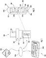
- the sprinkler head 200 may comprise a sprinkler body 210 and a frangible sprinkler bulb 220 that may be connected to the body 210.
- the frangible sprinkler bulb 220 may include a cylindrical wall 235 and an RFID (radio frequency identification) circuit 230.
- the RFID circuit 230 may be embedded in the cylindrical wall 235.
- the RFID circuit 230 may include an antenna 240 and a microchip 250 operationally connected to the antenna 240.
- the antenna 240 may extend between opposing axial ends generally referred to as 260 of the cylindrical wall 235.
- the microchip 250 may be disposed axially mid-span of the opposing axial ends 260 of the cylindrical wall 235.
- the opposing axial ends 260 of the cylindrical wall 235 may include a first end 260a and a second end 260b.
- the antenna 240 may include a plurality of axially extending portions generally referenced as 270 including first portion 270a and a second portion 270b.
- the first portion 27a may extend between the microchip 250 and the first end 260a of the cylindrical wall 235.
- the second portion 270b may extend between the microchip 250 and the second end 260 of the cylindrical wall 235.
- the first portion 270a of the antenna 240 and the second portion 270b of the antenna 240 may each comprise a periodic waveform pattern generally referenced as 280.
- the periodic waveform pattern 280 may propagate toward respective axial ends 260 of the sprinkler bulb 220.
- the periodic waveform pattern 280 may be a square waveform.
- the cylindrical wall 235 may include a plurality of surfaces generally referenced as 290, including an inner surface 290a (illustrated schematically) and an outer surface 290b.
- the RFID circuit 230 may be embedded in one of the plurality of surfaces 290 so as to render the RFID circuit 230 tamper-proof, for example, relative to an RFID tag.
- a mounting adaptor 300 may be provided for connecting the sprinkler head 200 with a supply conduit 310.
- a seal 320 may be provided for fluidly isolating the bulb 220 from the supply conduit 310.
- the sprinkler head 200 may be part of a fire detection system generally referenced as 350, which may include a system controller 350a that may be configured to electronically communicate with the RFID circuit 230 over a network 350b.
- a system controller 350a may be configured to electronically communicate with the RFID circuit 230 over a network 350b.
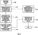
- the controller 350a may be configured for performing step S100 of monitoring for system alerts.
- Step S100 may include step S110 of communicating with the RFID circuit 230 in the sprinkler head 200 to obtain a status of the sprinkler head 200.
- the controller may perform the step of determining that a fire condition exists by identifying a communication break with the RFID circuit 230.
- step S110 of communicating with the RFID circuit 230 may include step S130 of the controller 350a periodically communicating with the RFID circuit 230 in the sprinkler head 200 to obtain the status of the sprinkler head 200. For example, the controller may communicate every second with the RFID circuit so that a fire situation is not missed.
- the controller 350a may identify a location of the RFID circuit 230 based on information stored in the RFID circuit 230, thereby identifying a location of the fire condition.
- the controller 350a may at step S150 provide one or more alerts for example to a fire station 350c over the same network 350b or a different network. The alerts may include identifying a fire at a location of the sprinkler head 200.
- the process that began at step S100 may end with respect to the sprinkler head 200.
- the above disclosed embodiments further provide a method for detecting a fire.
- the method may include a monitoring system detecting a brake in the RFID antenna, which results from fragmentation of the bulb during a fire condition.
- the monitoring system may render a determination that a fire condition exists when it is unable to communicate with the RFID chip.
- One benefit of the disclosed embodiments may include reducing manufacturing time and efforts for fire sprinklers that otherwise include frangible bulbs and RFID tags. Another benefit may include increasing a reliability of identifying a location of a fire. A reliability of a fire detection system may be unaffected by implementing the disclosed embodiments because modifications to the frangible bulb as provided herein are isolated from utilized water distribution implements. The bulbs disclosed herein may be tracked as soon as the bulbs are manufactured rather than having to be later equipped with a separate RFID tag. Additionally, the antenna may be embedded within a bulb surface utilizing low cost manufacturing processes.
- Disclosed embodiments identify one or more controllers and circuits that may utilize processor-implemented processes and devices for practicing those processes, such as a processor.
- Embodiments can also be in the form of computer program code containing instructions embodied in tangible media, such as network cloud storage, SD cards, flash drives, floppy diskettes, CD ROMs, hard drives, or any other computer-readable storage medium, wherein, when the computer program code is loaded into and executed by a computer, the computer becomes a device for practicing the embodiments.
- Embodiments can also be in the form of computer program code, for example, whether stored in a storage medium, loaded into and/or executed by a computer, or transmitted over some transmission medium, loaded into and/or executed by a computer, or transmitted over some transmission medium, such as over electrical wiring or cabling, through fiber optics, or via electromagnetic radiation, wherein, when the computer program code is loaded into an executed by a computer, the computer becomes an device for practicing the embodiments.
- the computer program code segments configure the microprocessor to create specific logic circuits.
Landscapes
- Health & Medical Sciences (AREA)
- Public Health (AREA)
- Business, Economics & Management (AREA)
- Emergency Management (AREA)
- Fire-Extinguishing By Fire Departments, And Fire-Extinguishing Equipment And Control Thereof (AREA)
Priority Applications (6)
| Application Number | Priority Date | Filing Date | Title |
|---|---|---|---|
| ES19397506T ES2879852T3 (es) | 2019-03-01 | 2019-03-01 | Cabezal de rociador con un bulbo que tiene un circuito de RFID integrado |
| EP19397506.7A EP3702003B1 (fr) | 2019-03-01 | 2019-03-01 | Tête d'arroseur comportant une ampoule dotée d'un circuit rfid intégré |
| DK19397506.7T DK3702003T3 (da) | 2019-03-01 | 2019-03-01 | Sprinklerdyse med en kolbe med et indlejret rfid-kredsløb |
| US16/800,324 US11364400B2 (en) | 2019-03-01 | 2020-02-25 | Sprinkler head with a bulb having an embedded RFID circuit |
| CA3074224A CA3074224A1 (fr) | 2019-03-01 | 2020-02-27 | Tete d`extincteur avec sonde ayant un circuit frid integre |
| RU2020108785A RU2020108785A (ru) | 2019-03-01 | 2020-02-28 | Спринклерная головка с термоколбой, содержащей встроенную схему рчи |
Applications Claiming Priority (1)
| Application Number | Priority Date | Filing Date | Title |
|---|---|---|---|
| EP19397506.7A EP3702003B1 (fr) | 2019-03-01 | 2019-03-01 | Tête d'arroseur comportant une ampoule dotée d'un circuit rfid intégré |
Publications (2)
| Publication Number | Publication Date |
|---|---|
| EP3702003A1 true EP3702003A1 (fr) | 2020-09-02 |
| EP3702003B1 EP3702003B1 (fr) | 2021-04-28 |
Family
ID=65817952
Family Applications (1)
| Application Number | Title | Priority Date | Filing Date |
|---|---|---|---|
| EP19397506.7A Active EP3702003B1 (fr) | 2019-03-01 | 2019-03-01 | Tête d'arroseur comportant une ampoule dotée d'un circuit rfid intégré |
Country Status (6)
| Country | Link |
|---|---|
| US (1) | US11364400B2 (fr) |
| EP (1) | EP3702003B1 (fr) |
| CA (1) | CA3074224A1 (fr) |
| DK (1) | DK3702003T3 (fr) |
| ES (1) | ES2879852T3 (fr) |
| RU (1) | RU2020108785A (fr) |
Cited By (2)
| Publication number | Priority date | Publication date | Assignee | Title |
|---|---|---|---|---|
| JP2021049338A (ja) * | 2019-09-20 | 2021-04-01 | マリオフ コーポレイション オイ | スプリンクラ装置、消火システム、スプリンクラバルブ、およびスプリンクラバルブの完全性を試験する方法 |
| EP4035746A1 (fr) * | 2021-02-02 | 2022-08-03 | Carrier Corporation | Dispositif d'arroseur |
Families Citing this family (5)
| Publication number | Priority date | Publication date | Assignee | Title |
|---|---|---|---|---|
| US11465004B2 (en) | 2018-02-12 | 2022-10-11 | Tyco Fire Products Lp | Microwave fire protection systems and methods |
| FI3597274T3 (fi) | 2018-07-16 | 2023-03-25 | Marioff Corp Oy | Sprinklerijärjestelmä sisältäen sprinklerin ja identifiointilaitteen |
| EP3702003B1 (fr) * | 2019-03-01 | 2021-04-28 | Marioff Corporation OY | Tête d'arroseur comportant une ampoule dotée d'un circuit rfid intégré |
| EP3753607B1 (fr) * | 2019-06-17 | 2025-02-26 | Marioff Corporation OY | Ampoule d'arroseur |
| ES3063067T3 (en) * | 2021-05-07 | 2026-04-15 | Marioff Corp Oy | Bulb device |
Citations (3)
| Publication number | Priority date | Publication date | Assignee | Title |
|---|---|---|---|---|
| WO2002040101A1 (fr) * | 2000-11-16 | 2002-05-23 | Axel Kretzschmar | Installation de lutte contre l'incendie equipee de detecteurs a recipients en verre |
| WO2005119585A1 (fr) * | 2004-06-02 | 2005-12-15 | Matsushita Electric Industrial Co., Ltd. | Balise de reconnaissance d’état |
| CN205391507U (zh) * | 2016-03-01 | 2016-07-27 | 浙江利高消防科技有限公司 | 一种贮压式厨房自动灭火设备 |
Family Cites Families (29)
| Publication number | Priority date | Publication date | Assignee | Title |
|---|---|---|---|---|
| GB8723226D0 (en) | 1987-10-02 | 1987-11-04 | Bolton & Johnson Ltd Thomas | Fire sprinklers |
| ATE166170T1 (de) | 1991-07-10 | 1998-05-15 | Samsung Electronics Co Ltd | Bewegliche überwachungsvorrichtung |
| US7143834B2 (en) | 2001-11-01 | 2006-12-05 | Kevin Michael Dolan | Sprinkler assembly |
| JP2006115725A (ja) | 2004-10-20 | 2006-05-11 | Ckd Corp | 散水システム |
| EP1888254B1 (fr) | 2005-06-03 | 2019-08-07 | Tyco Fire Products LP | Unite de commande de liberation pour systeme de protection contre l'incendie domestique |
| US7633393B2 (en) * | 2006-04-17 | 2009-12-15 | Honeywell International Inc. | Sprinkler status indicator |
| US9153107B2 (en) | 2008-09-10 | 2015-10-06 | Kathleen A. Austin | Multi-sensory alarming device |
| US8002046B2 (en) | 2008-10-10 | 2011-08-23 | Neeb Daniel A | Apparatus for reducing the incidence of tampering with automatic fire sprinkler assemblies |
| BRPI0923661A2 (pt) | 2008-12-31 | 2020-08-11 | Sang-Sun Lee | asperor com válvula integrada e sistema de extinção de incêncio utilizando o mesmo |
| US8307906B2 (en) | 2009-02-03 | 2012-11-13 | Victaulic Company | Apparatus and method for automatic conversion of sprinkler system |
| US9700746B2 (en) | 2009-04-16 | 2017-07-11 | South-Tek Systems, LLC | Gas purging valve for fire protection system |
| CN201489564U (zh) | 2009-09-10 | 2010-05-26 | 中山达华智能科技股份有限公司 | 一种微型rfid玻璃管电子标签 |
| KR101167145B1 (ko) | 2009-09-16 | 2012-07-24 | 이우성 | 물의 위치에너지를 이용한 소방 방재 시스템 |
| EP2586496A1 (fr) | 2010-06-24 | 2013-05-01 | Hochiki Corporation | Dispositif anti-incendie |
| DE202012100623U1 (de) | 2012-02-24 | 2012-03-22 | Job Lizenz Gmbh & Co. Kg | Brandschutzeinrichtung für elektrische Kleingeräte |
| US20160354626A1 (en) | 2013-07-19 | 2016-12-08 | Firestrike Industries Llc | Automatic fire targeting and extinguishing apparatus and method |
| GB2521857B (en) | 2014-01-06 | 2016-04-13 | Bernard Mapleston David | Long Range UHF RFID Tag for bottles stored on wine racks |
| DE202014101880U1 (de) | 2014-04-22 | 2014-05-13 | Job Lizenz Gmbh & Co Kg | Kompakte Miniatur-Feuerlösch- bzw. Brandschutzeinrichtung |
| US9530090B2 (en) | 2014-05-20 | 2016-12-27 | Dirac Solutions Inc. | Secure RFID tag or sensor with self-destruction mechanism upon tampering |
| WO2015191619A1 (fr) | 2014-06-09 | 2015-12-17 | Tyco Fire Products Lp | Système commandé et procédés pour la protection de marchandises contre l'incendie |
| US9403046B2 (en) | 2014-11-05 | 2016-08-02 | WWTemplar LLC | Remote control of fire suppression systems |
| US9993675B2 (en) | 2014-11-14 | 2018-06-12 | R&D Fire Solutions Inc. | Pre-action sprinkler head |
| US9542637B2 (en) | 2014-12-31 | 2017-01-10 | Intermec, Inc. | RFID tag with anti-tamper assembly |
| RU2652587C2 (ru) | 2015-11-18 | 2018-04-26 | Общество С Ограниченной Ответственностью "Форносовский Литейно-Механический Завод" | Спринклер с контролем срабатывания |
| US9672712B1 (en) | 2016-05-06 | 2017-06-06 | William E. Akers | Retrofit self-annunciating sprinkler |
| WO2017200390A1 (fr) | 2016-05-16 | 2017-11-23 | David John Picton | Soupape d'alarme incendie |
| US20180200552A1 (en) | 2017-01-16 | 2018-07-19 | Shalom Wertsberger | Fire containment system, devices and methods for same and for firefighting systems |
| US20180286218A1 (en) | 2017-04-03 | 2018-10-04 | Cease Fire, Llc | Wireless fire-protection system |
| EP3702003B1 (fr) * | 2019-03-01 | 2021-04-28 | Marioff Corporation OY | Tête d'arroseur comportant une ampoule dotée d'un circuit rfid intégré |
-
2019
- 2019-03-01 EP EP19397506.7A patent/EP3702003B1/fr active Active
- 2019-03-01 DK DK19397506.7T patent/DK3702003T3/da active
- 2019-03-01 ES ES19397506T patent/ES2879852T3/es active Active
-
2020
- 2020-02-25 US US16/800,324 patent/US11364400B2/en active Active
- 2020-02-27 CA CA3074224A patent/CA3074224A1/fr active Pending
- 2020-02-28 RU RU2020108785A patent/RU2020108785A/ru unknown
Patent Citations (3)
| Publication number | Priority date | Publication date | Assignee | Title |
|---|---|---|---|---|
| WO2002040101A1 (fr) * | 2000-11-16 | 2002-05-23 | Axel Kretzschmar | Installation de lutte contre l'incendie equipee de detecteurs a recipients en verre |
| WO2005119585A1 (fr) * | 2004-06-02 | 2005-12-15 | Matsushita Electric Industrial Co., Ltd. | Balise de reconnaissance d’état |
| CN205391507U (zh) * | 2016-03-01 | 2016-07-27 | 浙江利高消防科技有限公司 | 一种贮压式厨房自动灭火设备 |
Cited By (4)
| Publication number | Priority date | Publication date | Assignee | Title |
|---|---|---|---|---|
| JP2021049338A (ja) * | 2019-09-20 | 2021-04-01 | マリオフ コーポレイション オイ | スプリンクラ装置、消火システム、スプリンクラバルブ、およびスプリンクラバルブの完全性を試験する方法 |
| JP7460493B2 (ja) | 2019-09-20 | 2024-04-02 | マリオフ コーポレイション オイ | スプリンクラ装置、消火システム、スプリンクラバルブ、およびスプリンクラバルブの完全性を試験する方法 |
| EP4035746A1 (fr) * | 2021-02-02 | 2022-08-03 | Carrier Corporation | Dispositif d'arroseur |
| US12330005B2 (en) | 2021-02-02 | 2025-06-17 | Carrier Corporation | Sprinkler device |
Also Published As
| Publication number | Publication date |
|---|---|
| CA3074224A1 (fr) | 2020-09-01 |
| US20200276464A1 (en) | 2020-09-03 |
| RU2020108785A (ru) | 2021-08-30 |
| ES2879852T3 (es) | 2021-11-23 |
| US11364400B2 (en) | 2022-06-21 |
| DK3702003T3 (da) | 2021-06-21 |
| EP3702003B1 (fr) | 2021-04-28 |
Similar Documents
| Publication | Publication Date | Title |
|---|---|---|
| EP3702003B1 (fr) | Tête d'arroseur comportant une ampoule dotée d'un circuit rfid intégré | |
| EP2784015B1 (fr) | Système et procédé pour empêcher l'utilisation de produits pirate dans une commande d'ascenseur | |
| CN106656683B (zh) | 一种无人机通信链路故障检测装置及方法 | |
| JP2017078709A (ja) | 少なくとも一つの第1の車両の少なくとも一つの第1のセンサの少なくとも一つのセンサ機能不全を識別するための方法及び装置 | |
| RU2018142253A (ru) | Способы и устройство для соединения с возможностью передачи данных полевых устройств с удаленным терминальным блоком | |
| EP3690842A1 (fr) | Détecteur de fumée avec vaporisateur intégré pour exécuter des autotests | |
| US20130335197A1 (en) | Electronic system comprising of a plurality of electronic equipment units, electronic equipment for such a system and method for management and maintenance of such a system | |
| US10601843B2 (en) | Communication method, non-transitory computer-readable recording medium and communication device using same | |
| EP3199205B1 (fr) | Harnais antichute avec indicateur de lésions | |
| EP2921988A1 (fr) | Système de synchronisation de sport | |
| CN104007456A (zh) | 能自动读取电子车牌的北斗车载终端及其使用方法 | |
| CN109240971A (zh) | 通信方法、装置及系统 | |
| CN104125218A (zh) | 一种设备识别方法、装置以及系统 | |
| CN104539007A (zh) | 给电池监控单元分配标识信息的方法和装置 | |
| CN112666921A (zh) | 车载控制模块的故障处理方法、装置和车载控制模块 | |
| US20130265865A1 (en) | Communication device, and wiring state detection method and non-transitory computer-readable medium storing program using communication device | |
| US10055679B2 (en) | RFID transponder and methods for associating with a vehicle fuel tank | |
| CN104199438B (zh) | 车辆远程诊断方法及设备 | |
| US20090106749A1 (en) | System, method, and computer software code for determining whether a change in a subsystem is compatible with a system | |
| WO2019089597A1 (fr) | Système d'enregistreur d'aéronef distribué | |
| JP7185564B2 (ja) | 亀裂検知用ラベル | |
| US9030348B2 (en) | Systems and methods for providing diversity-distance-measuring equipment | |
| CN104953195A (zh) | 基于电阻评估车辆组件完整性的方法和系统 | |
| CN105573941A (zh) | 一种多源数据综合处理方法 | |
| WO2020238853A1 (fr) | Identification d'un équipement de sécurité dans un véhicule |
Legal Events
| Date | Code | Title | Description |
|---|---|---|---|
| PUAI | Public reference made under article 153(3) epc to a published international application that has entered the european phase |
Free format text: ORIGINAL CODE: 0009012 |
|
| STAA | Information on the status of an ep patent application or granted ep patent |
Free format text: STATUS: REQUEST FOR EXAMINATION WAS MADE |
|
| 17P | Request for examination filed |
Effective date: 20200507 |
|
| AK | Designated contracting states |
Kind code of ref document: A1 Designated state(s): AL AT BE BG CH CY CZ DE DK EE ES FI FR GB GR HR HU IE IS IT LI LT LU LV MC MK MT NL NO PL PT RO RS SE SI SK SM TR |
|
| AX | Request for extension of the european patent |
Extension state: BA ME |
|
| GRAJ | Information related to disapproval of communication of intention to grant by the applicant or resumption of examination proceedings by the epo deleted |
Free format text: ORIGINAL CODE: EPIDOSDIGR1 |
|
| STAA | Information on the status of an ep patent application or granted ep patent |
Free format text: STATUS: GRANT OF PATENT IS INTENDED |
|
| GRAP | Despatch of communication of intention to grant a patent |
Free format text: ORIGINAL CODE: EPIDOSNIGR1 |
|
| INTG | Intention to grant announced |
Effective date: 20201203 |
|
| GRAS | Grant fee paid |
Free format text: ORIGINAL CODE: EPIDOSNIGR3 |
|
| GRAA | (expected) grant |
Free format text: ORIGINAL CODE: 0009210 |
|
| STAA | Information on the status of an ep patent application or granted ep patent |
Free format text: STATUS: THE PATENT HAS BEEN GRANTED |
|
| AK | Designated contracting states |
Kind code of ref document: B1 Designated state(s): AL AT BE BG CH CY CZ DE DK EE ES FI FR GB GR HR HU IE IS IT LI LT LU LV MC MK MT NL NO PL PT RO RS SE SI SK SM TR |
|
| REG | Reference to a national code |
Ref country code: GB Ref legal event code: FG4D |
|
| REG | Reference to a national code |
Ref country code: CH Ref legal event code: EP |
|
| REG | Reference to a national code |
Ref country code: AT Ref legal event code: REF Ref document number: 1386448 Country of ref document: AT Kind code of ref document: T Effective date: 20210515 |
|
| REG | Reference to a national code |
Ref country code: DE Ref legal event code: R096 Ref document number: 602019004289 Country of ref document: DE |
|
| REG | Reference to a national code |
Ref country code: IE Ref legal event code: FG4D |
|
| REG | Reference to a national code |
Ref country code: DK Ref legal event code: T3 Effective date: 20210617 |
|
| REG | Reference to a national code |
Ref country code: SE Ref legal event code: TRGR |
|
| REG | Reference to a national code |
Ref country code: FI Ref legal event code: FGE |
|
| REG | Reference to a national code |
Ref country code: LT Ref legal event code: MG9D |
|
| REG | Reference to a national code |
Ref country code: NO Ref legal event code: T2 Effective date: 20210428 |
|
| REG | Reference to a national code |
Ref country code: AT Ref legal event code: MK05 Ref document number: 1386448 Country of ref document: AT Kind code of ref document: T Effective date: 20210428 |
|
| PG25 | Lapsed in a contracting state [announced via postgrant information from national office to epo] |
Ref country code: LT Free format text: LAPSE BECAUSE OF FAILURE TO SUBMIT A TRANSLATION OF THE DESCRIPTION OR TO PAY THE FEE WITHIN THE PRESCRIBED TIME-LIMIT Effective date: 20210428 Ref country code: HR Free format text: LAPSE BECAUSE OF FAILURE TO SUBMIT A TRANSLATION OF THE DESCRIPTION OR TO PAY THE FEE WITHIN THE PRESCRIBED TIME-LIMIT Effective date: 20210428 Ref country code: NL Free format text: LAPSE BECAUSE OF FAILURE TO SUBMIT A TRANSLATION OF THE DESCRIPTION OR TO PAY THE FEE WITHIN THE PRESCRIBED TIME-LIMIT Effective date: 20210428 Ref country code: AT Free format text: LAPSE BECAUSE OF FAILURE TO SUBMIT A TRANSLATION OF THE DESCRIPTION OR TO PAY THE FEE WITHIN THE PRESCRIBED TIME-LIMIT Effective date: 20210428 Ref country code: BG Free format text: LAPSE BECAUSE OF FAILURE TO SUBMIT A TRANSLATION OF THE DESCRIPTION OR TO PAY THE FEE WITHIN THE PRESCRIBED TIME-LIMIT Effective date: 20210728 |
|
| REG | Reference to a national code |
Ref country code: ES Ref legal event code: FG2A Ref document number: 2879852 Country of ref document: ES Kind code of ref document: T3 Effective date: 20211123 |
|
| PG25 | Lapsed in a contracting state [announced via postgrant information from national office to epo] |
Ref country code: LV Free format text: LAPSE BECAUSE OF FAILURE TO SUBMIT A TRANSLATION OF THE DESCRIPTION OR TO PAY THE FEE WITHIN THE PRESCRIBED TIME-LIMIT Effective date: 20210428 Ref country code: PL Free format text: LAPSE BECAUSE OF FAILURE TO SUBMIT A TRANSLATION OF THE DESCRIPTION OR TO PAY THE FEE WITHIN THE PRESCRIBED TIME-LIMIT Effective date: 20210428 Ref country code: RS Free format text: LAPSE BECAUSE OF FAILURE TO SUBMIT A TRANSLATION OF THE DESCRIPTION OR TO PAY THE FEE WITHIN THE PRESCRIBED TIME-LIMIT Effective date: 20210428 Ref country code: PT Free format text: LAPSE BECAUSE OF FAILURE TO SUBMIT A TRANSLATION OF THE DESCRIPTION OR TO PAY THE FEE WITHIN THE PRESCRIBED TIME-LIMIT Effective date: 20210830 Ref country code: GR Free format text: LAPSE BECAUSE OF FAILURE TO SUBMIT A TRANSLATION OF THE DESCRIPTION OR TO PAY THE FEE WITHIN THE PRESCRIBED TIME-LIMIT Effective date: 20210729 Ref country code: IS Free format text: LAPSE BECAUSE OF FAILURE TO SUBMIT A TRANSLATION OF THE DESCRIPTION OR TO PAY THE FEE WITHIN THE PRESCRIBED TIME-LIMIT Effective date: 20210828 |
|
| REG | Reference to a national code |
Ref country code: NL Ref legal event code: MP Effective date: 20210428 |
|
| PG25 | Lapsed in a contracting state [announced via postgrant information from national office to epo] |
Ref country code: SK Free format text: LAPSE BECAUSE OF FAILURE TO SUBMIT A TRANSLATION OF THE DESCRIPTION OR TO PAY THE FEE WITHIN THE PRESCRIBED TIME-LIMIT Effective date: 20210428 Ref country code: EE Free format text: LAPSE BECAUSE OF FAILURE TO SUBMIT A TRANSLATION OF THE DESCRIPTION OR TO PAY THE FEE WITHIN THE PRESCRIBED TIME-LIMIT Effective date: 20210428 Ref country code: SM Free format text: LAPSE BECAUSE OF FAILURE TO SUBMIT A TRANSLATION OF THE DESCRIPTION OR TO PAY THE FEE WITHIN THE PRESCRIBED TIME-LIMIT Effective date: 20210428 Ref country code: RO Free format text: LAPSE BECAUSE OF FAILURE TO SUBMIT A TRANSLATION OF THE DESCRIPTION OR TO PAY THE FEE WITHIN THE PRESCRIBED TIME-LIMIT Effective date: 20210428 Ref country code: CZ Free format text: LAPSE BECAUSE OF FAILURE TO SUBMIT A TRANSLATION OF THE DESCRIPTION OR TO PAY THE FEE WITHIN THE PRESCRIBED TIME-LIMIT Effective date: 20210428 |
|
| REG | Reference to a national code |
Ref country code: DE Ref legal event code: R097 Ref document number: 602019004289 Country of ref document: DE |
|
| PLBE | No opposition filed within time limit |
Free format text: ORIGINAL CODE: 0009261 |
|
| STAA | Information on the status of an ep patent application or granted ep patent |
Free format text: STATUS: NO OPPOSITION FILED WITHIN TIME LIMIT |
|
| 26N | No opposition filed |
Effective date: 20220131 |
|
| PG25 | Lapsed in a contracting state [announced via postgrant information from national office to epo] |
Ref country code: IS Free format text: LAPSE BECAUSE OF FAILURE TO SUBMIT A TRANSLATION OF THE DESCRIPTION OR TO PAY THE FEE WITHIN THE PRESCRIBED TIME-LIMIT Effective date: 20210828 Ref country code: AL Free format text: LAPSE BECAUSE OF FAILURE TO SUBMIT A TRANSLATION OF THE DESCRIPTION OR TO PAY THE FEE WITHIN THE PRESCRIBED TIME-LIMIT Effective date: 20210428 |
|
| PG25 | Lapsed in a contracting state [announced via postgrant information from national office to epo] |
Ref country code: MC Free format text: LAPSE BECAUSE OF FAILURE TO SUBMIT A TRANSLATION OF THE DESCRIPTION OR TO PAY THE FEE WITHIN THE PRESCRIBED TIME-LIMIT Effective date: 20210428 |
|
| REG | Reference to a national code |
Ref country code: CH Ref legal event code: PL |
|
| REG | Reference to a national code |
Ref country code: BE Ref legal event code: MM Effective date: 20220331 |
|
| PG25 | Lapsed in a contracting state [announced via postgrant information from national office to epo] |
Ref country code: LU Free format text: LAPSE BECAUSE OF NON-PAYMENT OF DUE FEES Effective date: 20220301 Ref country code: LI Free format text: LAPSE BECAUSE OF NON-PAYMENT OF DUE FEES Effective date: 20220331 Ref country code: IE Free format text: LAPSE BECAUSE OF NON-PAYMENT OF DUE FEES Effective date: 20220301 Ref country code: CH Free format text: LAPSE BECAUSE OF NON-PAYMENT OF DUE FEES Effective date: 20220331 |
|
| PG25 | Lapsed in a contracting state [announced via postgrant information from national office to epo] |
Ref country code: BE Free format text: LAPSE BECAUSE OF NON-PAYMENT OF DUE FEES Effective date: 20220331 |
|
| PG25 | Lapsed in a contracting state [announced via postgrant information from national office to epo] |
Ref country code: MK Free format text: LAPSE BECAUSE OF FAILURE TO SUBMIT A TRANSLATION OF THE DESCRIPTION OR TO PAY THE FEE WITHIN THE PRESCRIBED TIME-LIMIT Effective date: 20210428 Ref country code: CY Free format text: LAPSE BECAUSE OF FAILURE TO SUBMIT A TRANSLATION OF THE DESCRIPTION OR TO PAY THE FEE WITHIN THE PRESCRIBED TIME-LIMIT Effective date: 20210428 |
|
| PG25 | Lapsed in a contracting state [announced via postgrant information from national office to epo] |
Ref country code: HU Free format text: LAPSE BECAUSE OF FAILURE TO SUBMIT A TRANSLATION OF THE DESCRIPTION OR TO PAY THE FEE WITHIN THE PRESCRIBED TIME-LIMIT; INVALID AB INITIO Effective date: 20190301 |
|
| PG25 | Lapsed in a contracting state [announced via postgrant information from national office to epo] |
Ref country code: MT Free format text: LAPSE BECAUSE OF FAILURE TO SUBMIT A TRANSLATION OF THE DESCRIPTION OR TO PAY THE FEE WITHIN THE PRESCRIBED TIME-LIMIT Effective date: 20210428 |
|
| PGFP | Annual fee paid to national office [announced via postgrant information from national office to epo] |
Ref country code: ES Payment date: 20250401 Year of fee payment: 7 |
|
| PG25 | Lapsed in a contracting state [announced via postgrant information from national office to epo] |
Ref country code: TR Free format text: LAPSE BECAUSE OF FAILURE TO SUBMIT A TRANSLATION OF THE DESCRIPTION OR TO PAY THE FEE WITHIN THE PRESCRIBED TIME-LIMIT Effective date: 20210428 |
|
| PGFP | Annual fee paid to national office [announced via postgrant information from national office to epo] |
Ref country code: SE Payment date: 20260219 Year of fee payment: 8 |
|
| PGFP | Annual fee paid to national office [announced via postgrant information from national office to epo] |
Ref country code: GB Payment date: 20260220 Year of fee payment: 8 |
|
| PGFP | Annual fee paid to national office [announced via postgrant information from national office to epo] |
Ref country code: NO Payment date: 20260223 Year of fee payment: 8 Ref country code: DK Payment date: 20260219 Year of fee payment: 8 Ref country code: DE Payment date: 20260219 Year of fee payment: 8 |
|
| PGFP | Annual fee paid to national office [announced via postgrant information from national office to epo] |
Ref country code: FI Payment date: 20260219 Year of fee payment: 8 Ref country code: IT Payment date: 20260219 Year of fee payment: 8 |
|
| PGFP | Annual fee paid to national office [announced via postgrant information from national office to epo] |
Ref country code: FR Payment date: 20260219 Year of fee payment: 8 |