EP3703501B1 - Appareil de cuisson avec un dispositif d'éclairage pour émettre des faisceaux lumineux - Google Patents
Appareil de cuisson avec un dispositif d'éclairage pour émettre des faisceaux lumineux Download PDFInfo
- Publication number
- EP3703501B1 EP3703501B1 EP18795360.9A EP18795360A EP3703501B1 EP 3703501 B1 EP3703501 B1 EP 3703501B1 EP 18795360 A EP18795360 A EP 18795360A EP 3703501 B1 EP3703501 B1 EP 3703501B1
- Authority
- EP
- European Patent Office
- Prior art keywords
- light
- door
- cooking appliance
- housing
- rays
- Prior art date
- Legal status (The legal status is an assumption and is not a legal conclusion. Google has not performed a legal analysis and makes no representation as to the accuracy of the status listed.)
- Active
Links
Images


Classifications
-
- A—HUMAN NECESSITIES
- A21—BAKING; EDIBLE DOUGHS
- A21B—BAKERS' OVENS; MACHINES OR EQUIPMENT FOR BAKING
- A21B3/00—Parts or accessories of ovens
- A21B3/10—Means for illuminating ovens
-
- F—MECHANICAL ENGINEERING; LIGHTING; HEATING; WEAPONS; BLASTING
- F24—HEATING; RANGES; VENTILATING
- F24C—DOMESTIC STOVES OR RANGES ; DETAILS OF DOMESTIC STOVES OR RANGES, OF GENERAL APPLICATION
- F24C15/00—Details
- F24C15/008—Illumination for oven cavities
-
- F—MECHANICAL ENGINEERING; LIGHTING; HEATING; WEAPONS; BLASTING
- F24—HEATING; RANGES; VENTILATING
- F24C—DOMESTIC STOVES OR RANGES ; DETAILS OF DOMESTIC STOVES OR RANGES, OF GENERAL APPLICATION
- F24C15/00—Details
- F24C15/02—Doors specially adapted for stoves or ranges
Definitions
- the invention relates to a cooking appliance comprising a housing in which a cooking chamber is formed.
- the cooking appliance further comprises a door that is movably arranged on the housing and is designed to close the cooking chamber.
- the cooking appliance further comprises a lighting device that has at least one light source. The lighting device is arranged on the housing with at least partial components.
- Cooking appliances such as ovens, steam cookers, or microwave ovens are known to have lighting devices. These can be used, for example, to illuminate the interior of the cooking chamber. This is known, for example, from the WO 2011/117037 A1 There, light sources are arranged externally to the door, and additional optical elements, such as reflectors, allow the light to be directed into the cooking chamber. Furthermore, it is also possible for a space in front of the cooking chamber to be illuminated by the light sources of the lighting device, for example, to illuminate an extended food tray from above.
- a household appliance for preparing food is known there. It provides for a lighting device to have a light source arranged in the front region of a housing and external to a door.
- a light guide is also arranged external to the door.
- a further light guide is arranged on the door, which, when the door is closed, couples with the light source external to the door, so that the light from the light source can be introduced into the door via the two light guides.
- the door-side light guide is arranged on the door so that it can move relative to the door.
- the FR 2 936 859 A1 an oven with a lighting device integrated into a control panel.
- One aspect of the invention relates to a cooking appliance with a housing in which a cooking chamber is formed.
- the cooking appliance furthermore has a door which is movably arranged on the housing and is designed to close the cooking chamber.
- the cooking appliance furthermore has a lighting device which has a light source.
- the lighting device is arranged at least with partial components on the housing.
- the lighting device has a first operating mode in which the light rays are emitted with a first luminous flux at a light exit area from the housing into the closed door and has at least a second operating mode in which the light rays are emitted with a second luminous flux, different from the first luminous flux, at the light exit area from the housing into an anteroom formed in front of the cooking chamber when the door is open.
- the light beams can be generated with individual light intensity in the different operating states.
- the feature of variable light intensity at at least one aperture is advantageous in this regard.
- the luminous flux is different from a state when a pulled-out food carrier in the anteroom of the cooking chamber is to be illuminated from above by at least one light source.
- the luminous intensity can then also be individually adjusted by this design of the individual luminous fluxes, which represents the quotient of the luminous flux divided by the solid angle.
- the two different luminous fluxes in the at least two different operating states differ by at least the value of 50 lumens.
- the difference in luminous flux in different operating states can also depend on the number of light sources in the lighting device, which are then used to individually illuminate, for example, an anteroom in front of the cooking chamber. The same can also depend on how many light sources are present in a lighting device and are used to couple light beams into the door when the door is closed.
- the lighting device has an optical device designed to specifically influence the light rays of the light source such that the light rays are focused at a focal point outside the housing.
- Such a design then makes it possible to focus the light rays emerging from the housing such that they are prepared for further use, for example, for coupling into a coupling area outside the housing. This makes it possible This makes it possible, for example, to design this coupling area to be relatively small and compact, while still coupling a high proportion of the light rays emerging from the housing and guided in a defined manner into the coupling area.
- this design also makes it possible to distribute the light rays further if coupling into a coupling area outside the housing is not intended, so that they can also directly illuminate an area outside the housing more effectively.
- this defined choice of external focal point allows the light rays to fan out again after the focal point to form a widened light cone in a defined manner, thus enabling large-area illumination at the desired distance.
- the optical device has at least one optically active focusing element, such as a converging lens or a parabolic mirror or the like, which is arranged in the housing.
- This housing-side optical focusing element is such that light rays emitted by the light source are bundled by this focusing element in such a way that a defined focal point is created in a defined manner outside the housing and thus when the light rays exit the housing.
- this at least one focus or this at least one focal point is formed or created at a defined distance from an outer wall of the housing.
- the distance is between 0 cm and 5 cm, in particular between 0 cm and 4 cm, in particular between 0 cm and 3 cm, in particular between 0 cm and 2 cm, for example between 0.5 cm and 1.5 cm.
- the focal point is thus placed relatively close to the housing, so that the fanning out of the light rays to form an expanded light cone after the focal point is advantageously achieved in that, for example, in the case of an extended food carrier, which thus forms in an anteroom to the cooking appliance (viewed in the depth direction of the cooking appliance), the largest possible area can be illuminated.
- This design therefore then such a fanning out enables that the food support is illuminated from above with this one light source over at least 50 percent of its surface, preferably over at least 70 percent of its surface.
- this defined distance also makes it particularly advantageous to enable the most comprehensive and area-compact coupling of these light rays emerging from the housing into a door of the cooking appliance when the door is closed. Since the door then usually rests against the housing or the coupling area of the door-side optical element is arranged in particular close to an outer wall of the housing from which the light rays of the light source emerge, such a close relocation of the focal point to the outer wall of the housing is advantageous in order to then enable the best possible and comprehensive coupling of the light rays into the door.
- the door has at least one optical element of the lighting device, into which light rays from the light source can preferably be coupled when the door is closed.
- the focal point is at a coupling end of the optical element or within a distance interval of preferably +/- 3 cm, in particular +/- 2 cm, in particular +/- 1 cm, viewed in the direction of light propagation.
- this coupling end has a surface area that is larger than the surface area of the focal point.
- This is another very advantageous embodiment, as it allows the light or light beams bundled at the focal point to be coupled into the door with a particularly large area.
- the lighting device comprises a light guide device arranged in the door.
- the light guide device when the door is closed, Light rays emitted by the light source can be emitted forwards out of the door and/or backwards out of the door when viewed in the depth direction of the cooking appliance.
- specific areas in front of the door and thus outside the cooking appliance can be individually illuminated when the door is closed.
- the lighting device is designed to illuminate an anteroom located in front of a loading opening of the cooking chamber in the depth direction of the cooking appliance when the door is open.
- the vestibule is positioned at a distance from the focal point such that the vestibule is illuminated with a light cone that widens again in the direction of propagation of the light rays after the focal point.
- this food carrier can be illuminated from above over a large area by this widened light cone, and in particular, very homogenously.
- the lighting device has a first operating mode in which the light rays are emitted from the housing at a light exit area with a first luminous flux.
- the lighting device has at least one second operating mode in which the light rays are emitted from the housing at the light exit area with a second luminous flux that is different from the first luminous flux.
- areas that are partially concealed, located in niches, or at the rear of the cooking chamber can also be improved in lighting and thus illuminated with individual brightness.
- Other effects such as unwanted glare or over-illumination of elements and/or areas can also be avoided in this way. This not only always achieves improved optical lighting with regard to the desired and adjusted brightness, but also enables a user-friendly perception of this lighting.
- the implementation of the first operating mode is coupled to a first position of the door and/or the implementation of the second operating mode is coupled to a second position of the door.
- the individual luminous flux of the lighting device is automatically adjusted depending on the respective position of the door. This can be done, for example, via a control unit.
- the first position of the door is a completely closed position and/or the second position of the door is a position in which an anteroom is formed in front of a loading opening of the cooking chamber, which anteroom is delimited at the bottom by the door.
- the luminous flux is higher in the first operating mode than in the second operating mode. Especially when the door is completely closed in the first operating mode, a higher luminous flux can then be generated in order to create sufficient lighting inside the cooking chamber, so that a user can better observe the cooking chamber even through the closed door.
- the radiation from the door can then also be external to the device and thus, for example, particularly towards the front with a higher luminous flux, so that individual lighting of areas in front is also improved here, even when the door is closed.
- components in the door that are to be individually illuminated can also be illuminated with a higher luminous flux, so that the frontal perception of an observer looking at the door from the front is improved.
- the at least one housing-side light source of the lighting device can be arranged, viewed in the depth direction, in the region of a control panel or a switch front or a flange, for example a flange of a muffle which delimits the cooking chamber with the walls, or else on a vertical front-side strip which is designed as a pilaster strip.
- the cooking appliance is provided with at least one light aperture serving as a planar light source for illuminating the anteroom when the door is open and is designed accordingly so that a correspondingly widened light cone is effective here.
- the housing-side optical element of the lighting device is advantageously designed such that it has a focusing effect and, in this regard, forms the external focal point on the housing side.
- the door-side optical element of the lighting device can be a light guide or a light guide connection.
- One or more optical fibers can be provided.
- at least one lens, a reflector, or a mirror can also be used.
- the aforementioned optical elements can be made of various materials, for example glass, silicone, PMMA, PC, PS, or the like.
- the lighting device has an optical element inside the door, the coupling region of which, into which the light rays emitted by the housing are coupled, is designed as an optically effective collection region.
- this collection region can be designed as a lens that is at least convex on one side or concave on one side.
- the lighting device thus preferably has at least two separate optical elements, of which one optical element is arranged outside the door and inside the housing, and the second optical element is arranged outside the housing and inside the door.
- these at least two optical elements are each designed as optical focusing elements.
- two lenses can be provided here, or a lens and a light guide configured as a fiber optic or light guide rod, or a lens and a mirror, or a lens and a reflector.
- the housing-side configuration of the optical element is such that this optical element has a focal point at a distance between 0.5 cm and 2 cm, in particular between 0.5 cm and 1.5 cm, in particular 1 cm.
- the optical element which is arranged on the housing side, is set back inwards towards the outer wall from which the light exits the housing. This protects this optical element accordingly. This also achieves a certain degree of protection against unwanted light scattering within the device.
- a tube section can be arranged between the lens and the outer wall, or a lateral aperture can be formed. This configuration with a tube section or aperture can also be such that the tube section or aperture is formed on the inside with, for example, a matte, dark surface.
- the additional optical element which is arranged on the door side, can be formed with a concave surface or flat at the coupling area. It can be provided that this light-collecting area of the optical element, which is arranged on the door side, is integrated and thus formed integrally with this optical element. This prevents further media transition of the light beams in the door between separate optical elements.
- this optical element in particular the coupling region, which is preferably designed as a light-collecting region, is arranged set back inward relative to an outer side of the door.
- this optical element is arranged in an upper region of the door, for example, in an upper cover, which is also referred to as the top panel.
- the lighting device is designed to generate light rays in a first light color and is designed at least to generate light rays in a second light color that is different from the first.
- the lighting device is designed to generate a continuous light from the light rays and/or a pulsed light from the light rays.
- different operating functions of the cooking appliance are visually displayed by the different light colors and/or different values of operating parameters of at least one operating function of the cooking appliance are visually displayed.
- the light source is a light-emitting diode. It can also be a multicolor light-emitting diode.
- the lighting device has a light source that generates light beams that can be used to illuminate a vestibule in the depth direction in front of the cooking chamber when the door is open, and that also generates light beams that are radiated from the housing into the door when the door is closed. Light beams for various uses or different specific lighting scenarios are then generated with a single light source.
- the lighting device preferably has at least two light sources, each of which is configured for the aforementioned functionality. These light sources are preferably arranged above the loading opening of the cooking chamber, viewed in the vertical direction of the cooking appliance, and, in particular, are arranged on opposite sides, viewed in the width direction.
- a further independent aspect of the invention relates to a cooking appliance comprising a housing in which a cooking chamber is formed.
- the cooking appliance further comprises a door.
- the door is movably arranged on the housing. It is further configured to close the cooking chamber.
- the cooking appliance further comprises a lighting device comprising at least one light source.
- the lighting device is arranged at least with partial components on the housing and at least with partial components external to the door.
- the lighting device has an optical device which is designed to specifically influence the light rays from the light source such that the light rays are bundled at a focal point outside the housing. Such a design then makes it possible to bundle the light rays emerging from the housing such that they are prepared for further use, for example for coupling into a coupling area external to the housing.
- this coupling area relatively small and compact and yet still couple a high proportion of the light rays emerging from the housing and guided in a defined manner into the coupling area.
- this design also makes it possible to further distribute the light rays if coupling into a coupling area external to the housing is not provided for, so that they can also directly illuminate an area external to the housing more effectively. Since, according to the laws of optics, the light rays expand after the focal point and form a specific light cone, this defined choice of the external focal point allows the light rays to fan out again after the focal point to form an expanded light cone, thus enabling large-area illumination at the desired distance.
- a further independent aspect of the invention relates to a cooking appliance having a housing in which a cooking chamber is formed.
- the cooking appliance further comprises a door which is movably arranged on the housing and which is designed to close the cooking chamber.
- the cooking appliance further comprises an illumination device having at least one light source.
- the illumination device is arranged at least with subcomponents on the housing.
- the illumination device has an optical device which has a first optical focusing element in the housing and which has a separate second optical focusing element which is arranged in the door.
- Embodiments of the above-mentioned first independent aspect of the invention are to be regarded as advantageous embodiments of the further independent aspects.
- top, bottom, front, “back”, “horizontal”, “vertical”, “depth direction”, “width direction”, “height direction” etc. indicate the positions and orientations given when the device is used and arranged as intended.
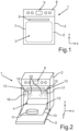
- FIG. 1 A front view of a cooking appliance 1 is shown, which may be, for example, an oven, a steam cooker, or a microwave cooker.
- the cooking appliance 1 has a housing 2 in which a cooking chamber 3 for preparing food is formed.
- the cooking chamber 3 is delimited by the walls of a muffle arranged in the housing 2.
- the muffle, and thus also the cooking chamber 3 has a loading opening 4 ( Fig. 2 ) which can be closed by a door 5.
- the door 5 is arranged pivotably on the housing 2.
- the door 5 has, for example, a handle 6 and is formed at least in part with a transparent area 7 through which, when the door 5 is closed, one can look through and thus into the cooking chamber 3.
- the cooking appliance 1 also has, viewed in the vertical direction (y-direction), above the door 5, a control panel 8 on which a control device 9 is arranged.
- the cooking appliance 1 is shown in a perspective view and with the door 5 open. Furthermore, Fig. 2 A separate food support 10 is shown, which can be, for example, a baking tray or a wire rack or the like. A food item 11 is placed on the food support 10, for example. The food support 10 is here pulled out of the cooking chamber 3 in the depth direction (z-direction) and is thus located in an anteroom 12 in front of the cooking chamber 3, viewed in the depth direction.
- the cooking appliance 1 further comprises a lighting device 13.
- the lighting device 13 comprises a first light source 14, which can be, for example, a light-emitting diode, in particular a multi-color light-emitting diode.
- the first light source 14 is arranged above the cooking chamber 3 and adjacent to the loading opening 4, viewed in the vertical direction (y-direction).
- a second light source 15 of the lighting device 13 is provided here.
- the two light sources 14 and 15 are arranged in the width direction (x-direction), on opposite sides of the housing 2 or arranged in the housing 2. They can be arranged, for example, in the area of the control panel 8 or on a respective vertical pilaster strip, which represents a front-side visible component. They can also be arranged, for example, on a front flange, in particular the muffle.
- These light sources 14 and 15 are thus arranged outside the door and represent subcomponents of the lighting device 13, which are arranged in the housing 2.
- Fig. 3 the cooking appliance 1 is in accordance with Fig. 2 shown in a side view.
- the anteroom 12 can be seen here. It is illuminated by the lighting device 13, in particular the light beams 16 and 17 of the light sources 14 and 15.
- the light beams 16, 17 each form an expanded light cone 22, which is directed obliquely forward and downward and illuminates the food support 10 from above.
- the lighting device 13 has an optical device 18, as shown in the exemplary illustration in Fig. 4 is shown.
- the optical device 18 is designed to influence the light beams of the light sources 14, 15 in a defined manner such that these light beams are bundled outside the housing 2 at a focal point 19.
- the focal point 19 is formed at a defined distance from an optical element 20 of the optical device 18 and thus in particular also at a defined distance from an outer wall 21 of the housing 2.
- a distance A is between 0 cm and 2 cm.
- the light rays 16, which are shown here as an example, are bundled in the focal point 19 and then widen again after the focal point 19, viewed in the direction of light propagation, and form the the light cone 22 already mentioned in this regard, as it is also shown in Fig. 2 and Fig. 3 can only be seen when door 5 is open.
- FIG. 5 An enlarged view of this light cone 22 can be seen in a schematic representation.
- the optical device 18 has an optical element 20 which is external to the door and internal to the housing and which is a first focusing element.
- the lighting device 13 has a further optical element 23 external to the housing and internal to the door, as is shown by way of example in Fig. 7 is shown.
- This further optical element 23 can, in an advantageous embodiment, also be designed as an at least regionally focusing element.
- this is achieved in that a coupling region 24 of this optical element 23 has a concave surface 25. Due to the orientation of the light rays 16 or 17 incident on the coupling region 24, this concave surface 25 has a collecting or bundling effect. With a different configuration and orientation of the light rays 16, 17 as they impinge on the light coupling region 24, this surface can also be designed differently, for example, be flat.
- this optical element 23, which is arranged in the door 5, thus has in particular a focusing region or light collecting region, which can also be integrated and thus formed in one piece with the optical element 23.
- This light coupling area 24, which represents a coupling end of the optical element 23, can couple in the light emitted from the housing 2 by the light sources 14 and 15 when the door 5 is closed.
- this optical element 23 is arranged in the door 5 in such a way that the coupling region 24 is arranged at the focal point 19 or within a distance interval of +/- 1.0 cm from this focal point 19 when the door 5 is closed.
- Fig. 6 in which a partial area of a vertical sectional view through the cooking appliance 1 with the door 5 closed is shown.
- the optical element 20 of the optical device 18, shown only symbolically here faces directly adjacent to the coupling area 24.
- This optical element 20 can, as shown in Fig. 4 shown, be arranged set back inwards relative to the outer wall 21.
- a diaphragm area or a tube section 26 may be provided. In an advantageous embodiment, this can be matt on the inside.
- this optical element 20, as shown in Fig. 6 is symbolically represented, extends up to the outer wall 21 or is even arranged standing beyond it.
- this coupling area 24 is opposite an outer side 27, as shown in Fig. 6 shown, the door 5 is set back inwards, at the focal point 19 or within the already mentioned distance interval of +/- 1.0 cm.
- the lighting device 13 when the door 5 is closed, radiates the light or light beams 16, 17 coupled into the optical element 23 via the optical device 18 out of the door 5 into the cooking chamber 3, as shown in Fig. 6 is indicated, and/or viewed in the depth direction, radiates away from the cooking chamber 3 to the front out of the door 5, as is also shown in Fig. 6 is indicated.
- the lighting device 13 has a light-guiding device 29 in the door 5, which offers these radiation possibilities when the door 5 is closed.
- the lighting device 13 has a first operating mode in which the light beams 16, 17, as emitted by the light sources 14, 15, are emitted from the housing 2 with a first luminous flux at a first light exit region, and the lighting device 13 has at least a second operating mode in which these light beams 16, 17 are emitted from the housing 2 with a second luminous flux that is different from the first luminous flux.
- the light exit area can be, for example, the exit opening on the outer wall 21 or the light output area 29 ( Fig. 4 ) of the optical element 20, which is the last optical element in front of the outer wall 21 in the direction of light propagation if there are several optical elements in the housing 2.
- the execution of the first operating mode is coupled to a first position of the door 5 and/or the execution of the second operating mode is coupled to a second position of the door.
- the first position of the door 5 can preferably be the fully closed position, as shown in Fig. 6 and Fig. 1 is shown.
- the second position of the door 5 is one in which an antechamber 12 is formed in front of the loading opening 4 of the cooking chamber 3, this antechamber 12 being delimited at the bottom by the at least partially open door 3.
- the lighting device 13 is designed to generate light beams 16, 17 in a first light color and at least to generate light beams 16, 17 in a second light color that is different from the first.
- the lighting device 13 is designed to generate a continuous light of the light beams 16, 17 and/or a pulsed light of the light beams 16, 17.
- an individual assignment to different operating states can then take place, so that, for example, in one operating state the light beams 16, 17 are generated in a continuous light, and in a second operating state a pulsed light of the light beams is generated.
- a specific operating function of the cooking appliance 1 is visually displayed and/or a specific value of an operating parameter of at least one operating function is visually displayed.
Landscapes
- Engineering & Computer Science (AREA)
- Chemical & Material Sciences (AREA)
- Combustion & Propulsion (AREA)
- Mechanical Engineering (AREA)
- General Engineering & Computer Science (AREA)
- Life Sciences & Earth Sciences (AREA)
- Food Science & Technology (AREA)
- Electric Ovens (AREA)
- Electric Stoves And Ranges (AREA)
- Arrangement Of Elements, Cooling, Sealing, Or The Like Of Lighting Devices (AREA)
Claims (10)
- Appareil de cuisson (1), comprenant un boîtier (2), dans lequel un espace de cuisson (3) est formé, une porte (5), qui est montée mobile sur le boîtier (2), et est conçue pour refermer l'espace de cuisson (3), et un dispositif d'éclairage (13), qui comprend une source de lumière (14, 15),dans lequel le dispositif d'éclairage (13) est disposé sur le boîtier (2),dans lequel le dispositif d'éclairage (13) comprend un premier mode de fonctionnement, dans lequel les rayons lumineux (16, 17) sont émis avec un premier flux lumineux au niveau d'une région de sortie de lumière (21, 29) à partir du boîtier (2) dans la porte fermée (5), et comprend au moins un deuxième mode de fonctionnement, dans lequel les rayons lumineux (16, 17) sont émis avec un deuxième flux lumineux différent du premier flux lumineux au niveau de la région de sortie de lumière (21, 29) à partir du boîtier (2) dans un espace avant (12) formé devant l'espace de cuisson (3) lorsque la porte (5) est ouverte,dans lequel la porte (5) comprend au moins un élément optique (23) du dispositif d'éclairage (13), dans lequel des rayons lumineux (16, 17) de la source de lumière (14, 15) peuvent être injectés à l'état fermé de la porte (5),dans lequel le dispositif d'éclairage (13) comprend un dispositif optique (18), qui est configuré pour diriger de façon définie les rayons lumineux (16, 17) de la source de lumière (14, 15) de manière à ce que les rayons lumineux (16, 17) soient concentrés en dehors du boîtier (2) dans un point focal (19),dans lequel le point focal (19) est situé, à l'état fermé de la porte (5), au niveau d'une extrémité d'injection (24) de l'élément optique (23) ou à une distance maximale de +/-3,0 cm de celle-ci.
- Appareil de cuisson (1) selon la revendication 1, caractérisé en ce que la première position de la porte (5) est une position entièrement fermée et/ou la deuxième position de la porte (5) est une position dans laquelle un espace avant (12) se forme devant une ouverture d'introduction (4) de l'espace de cuisson (3), qui est délimité vers le bas par la porte (5).
- Appareil de cuisson (1) selon l'une des revendications précédentes, caractérisé en ce que le point focal (19) est formé à une distance définie (a) d'une paroi extérieure (21) du boîtier (2).
- Appareil de cuisson (1) selon la revendication 3, caractérisé en ce que la distance (a) est de 0 cm à 5 cm.
- Appareil de cuisson (1) selon l'une des revendications précédentes, caractérisé en ce que l'extrémité d'injection (24) comprend une surface (25) qui est plus grande que la surface du point focal (19).
- Appareil de cuisson (1) selon l'une des revendications précédentes, caractérisé en ce que le dispositif d'éclairage (13) est configuré pour éclairer un espace avant (12) situé devant une ouverture d'introduction (4) de l'espace de cuisson (3) dans le sens de la profondeur (z) de l'appareil de cuisson (1), lorsque la porte (3) est ouverte,
dans lequel l'espace avant (12) est distant du point focal (19) de telle manière que l'éclairage de l'espace avant (12) est effectué avec un cône lumineux (22) à nouveau élargi après le point focal (19) dans la direction de diffusion des rayons lumineux (16, 17). - Appareil de cuisson (1) selon l'une des revendications précédentes, caractérisé en ce que la porte (5) comprend un dispositif de guidage de lumière (28) du dispositif d'éclairage (22), avec lequel, à l'état fermé de la porte (5), des rayons lumineux (16, 17) émis par la source de lumière (14, 15) peuvent être émis dans la direction de profondeur (z) de l'appareil de cuisson (1) vers l'avant de la porte (5) et/ou vers l'arrière de la porte (5).
- Appareil de cuisson (1) selon l'une des revendications précédentes, caractérisé en ce que le dispositif d'éclairage (13) est configuré pour produire des rayons lumineux (16, 17) dans une première couleur de lumière et est configuré au moins pour produire des rayons lumineux (16, 17) dans une deuxième couleur de lumière différente de la première couleur de lumière et/ou est configuré pour produire une lumière continue des rayons lumineux (16, 17) et/ou une lumière pulsée des rayons lumineux (16, 17).
- Appareil de cuisson (1) selon la revendication 8, caractérisé en ce que des fonctions opérationnelles différentes de l'appareil de cuisson (1) sont affichées optiquement par les couleurs de lumière différentes et/ou des valeurs différentes de paramètres de fonctionnement d'au moins une fonction opérationnelle de l'appareil de cuisson (1) sont affichées optiquement par des couleurs de lumière différentes, et/ou des fonctions opérationnelles différentes et/ou des valeurs différentes de paramètres de fonctionnement d'au moins une fonction opérationnelle de l'appareil de cuisson (1) sont affichées optiquement en fonction d'une fréquence de pulsation des rayons lumineux (16, 17).
- Appareil de cuisson (1) selon l'une des revendications précédentes, caractérisé en ce que la source de lumière (14, 15) est une diode électroluminescente, en particulier une diode électroluminescente à plusieurs couleurs.
Applications Claiming Priority (2)
| Application Number | Priority Date | Filing Date | Title |
|---|---|---|---|
| DE102017219500.2A DE102017219500A1 (de) | 2017-11-02 | 2017-11-02 | Gargerät mit einer Beleuchtungsvorrichtung, mit welcher abhängig von Betriebsfunktionen des Gargeräts Lichtstrahlen mit unterschiedlichem Lichtstrom abstrahlbar sind |
| PCT/EP2018/078836 WO2019086282A1 (fr) | 2017-11-02 | 2018-10-22 | Appareil de cuisson doté d'un dispositif d'éclairage destiné à émettre des faisceaux lumineux caractérisés par des flux lumineux différents en fonction des fonctions de l'appareil de cuisson |
Publications (2)
| Publication Number | Publication Date |
|---|---|
| EP3703501A1 EP3703501A1 (fr) | 2020-09-09 |
| EP3703501B1 true EP3703501B1 (fr) | 2025-04-16 |
Family
ID=64049105
Family Applications (1)
| Application Number | Title | Priority Date | Filing Date |
|---|---|---|---|
| EP18795360.9A Active EP3703501B1 (fr) | 2017-11-02 | 2018-10-22 | Appareil de cuisson avec un dispositif d'éclairage pour émettre des faisceaux lumineux |
Country Status (5)
| Country | Link |
|---|---|
| EP (1) | EP3703501B1 (fr) |
| DE (1) | DE102017219500A1 (fr) |
| ES (1) | ES3024637T3 (fr) |
| PL (1) | PL3703501T3 (fr) |
| WO (1) | WO2019086282A1 (fr) |
Families Citing this family (1)
| Publication number | Priority date | Publication date | Assignee | Title |
|---|---|---|---|---|
| SI26661A (sl) | 2024-07-02 | 2026-01-30 | Gorenje, d.o.o. | Kuhalni aparati z osvetljevalno napravo |
Citations (2)
| Publication number | Priority date | Publication date | Assignee | Title |
|---|---|---|---|---|
| FR2936859A1 (fr) * | 2008-10-03 | 2010-04-09 | Fagorbrandt Sas | Four de cuisson comprenant un dispositif d'eclairage integre dans un bandeau de commande. |
| DE102013208374B4 (de) * | 2013-05-07 | 2016-08-18 | Meiko Maschinenbau Gmbh & Co. Kg | Reinigungsvorrichtung mit beleuchtetem Türgriff |
Family Cites Families (6)
| Publication number | Priority date | Publication date | Assignee | Title |
|---|---|---|---|---|
| DE10204612A1 (de) * | 2001-10-25 | 2003-05-15 | Bsh Bosch Siemens Hausgeraete | Beleuchtungsreinrichtung für Backöfen |
| DE102007058942A1 (de) * | 2007-12-07 | 2009-06-10 | BSH Bosch und Siemens Hausgeräte GmbH | Gargerät |
| DE102009000655B3 (de) | 2009-02-06 | 2010-09-09 | BSH Bosch und Siemens Hausgeräte GmbH | Hausgerät zur Zubereitung von Lebensmitteln |
| DE102010003115A1 (de) | 2010-03-22 | 2011-09-22 | BSH Bosch und Siemens Hausgeräte GmbH | Gargerät |
| DE102012224034A1 (de) * | 2012-12-20 | 2014-06-26 | BSH Bosch und Siemens Hausgeräte GmbH | Beleuchtungseinrichtung für Gargeräte |
| DE102013205824A1 (de) * | 2013-04-03 | 2014-10-09 | BSH Bosch und Siemens Hausgeräte GmbH | Beleuchtungsvorrichtung für einen Innenraum eines Haushaltsgeräts sowie Haushaltsgerät mit einer derartigen Beleuchtungsvorrichtung |
-
2017
- 2017-11-02 DE DE102017219500.2A patent/DE102017219500A1/de not_active Withdrawn
-
2018
- 2018-10-22 WO PCT/EP2018/078836 patent/WO2019086282A1/fr not_active Ceased
- 2018-10-22 PL PL18795360.9T patent/PL3703501T3/pl unknown
- 2018-10-22 EP EP18795360.9A patent/EP3703501B1/fr active Active
- 2018-10-22 ES ES18795360T patent/ES3024637T3/es active Active
Patent Citations (2)
| Publication number | Priority date | Publication date | Assignee | Title |
|---|---|---|---|---|
| FR2936859A1 (fr) * | 2008-10-03 | 2010-04-09 | Fagorbrandt Sas | Four de cuisson comprenant un dispositif d'eclairage integre dans un bandeau de commande. |
| DE102013208374B4 (de) * | 2013-05-07 | 2016-08-18 | Meiko Maschinenbau Gmbh & Co. Kg | Reinigungsvorrichtung mit beleuchtetem Türgriff |
Also Published As
| Publication number | Publication date |
|---|---|
| PL3703501T3 (pl) | 2025-07-28 |
| ES3024637T3 (en) | 2025-06-04 |
| DE102017219500A1 (de) | 2019-05-02 |
| WO2019086282A1 (fr) | 2019-05-09 |
| EP3703501A1 (fr) | 2020-09-09 |
Similar Documents
| Publication | Publication Date | Title |
|---|---|---|
| EP2550486B1 (fr) | Appareil de cuisson et procédé permettant de faire fonctionner un appareil de cuisson | |
| DE102009044504B3 (de) | Dunstabzugshaube mit einer Beleuchtungseinrichtung | |
| DE102017006756B4 (de) | Farbtemperaturvariable Leuchtvorrichtung sowie elektrisches Haushaltsgerät mit einer solchen Leuchtvorrichtung | |
| DE102006061739A1 (de) | Muffel für einen Backofen und Verfahren zum Ausleuchten eines Garraums | |
| WO2022106463A1 (fr) | Appareil de cuisson équipé d'un éclairage de chambre de cuisson spécifique | |
| EP3008411B1 (fr) | Appareil de froid ménager doté d'un dispositif d'éclairage intérieur et doté d'étagères transparentes | |
| WO2019086281A1 (fr) | Appareil de cuisson doté d'un dispositif d'éclairage destiné à produire un point focal extérieur au boîtier | |
| WO2017088074A1 (fr) | Éclairage dans un four de cuisson | |
| EP3290810B1 (fr) | Luminaire pour appareils ménagers | |
| EP3762653B1 (fr) | Appareil électroménager comprenant un système d'affichage avec une image lumineuse à intensité variable, et procédé associé | |
| EP3703501B1 (fr) | Appareil de cuisson avec un dispositif d'éclairage pour émettre des faisceaux lumineux | |
| DE102015101099B4 (de) | Dunstabzugshaube | |
| DE102009001093B4 (de) | Hausgerät zur Zubereitung von Lebensmitteln und Verfahren zum Betreiben eines derartigen Hausgeräts | |
| EP3338025B1 (fr) | Dispositif de commande pour un appareil ménager comprenant un guide de lumière servant à l'éclairage de plusieurs zones d'un capot avant à des intensités de lumière différentes, appareil ménager comprenant un dispositif de commande de ce type, et procédé servant à faire fonctionner un dispositif de commande | |
| EP3465015B1 (fr) | Appareil électroménager pour préparer des aliments dans une partie extérieure affichant des informations optiques | |
| DE102016116446A1 (de) | Haushaltsgeräteleuchte | |
| EP3443268B1 (fr) | Porte pour un appareil électroménager et appareil de cuisson électroménager | |
| DE102013214000A1 (de) | Haushaltskältegerät mit zumindest einer Lichtquelle und einer Aufnahme für einen Auflageboden | |
| DE102015225859A1 (de) | Gargerät | |
| DE102013205824A1 (de) | Beleuchtungsvorrichtung für einen Innenraum eines Haushaltsgeräts sowie Haushaltsgerät mit einer derartigen Beleuchtungsvorrichtung | |
| DE102010030558B4 (de) | Dunstabzugshaube mit Beleuchtungsvorrichtung | |
| EP3745032A1 (fr) | Hotte aspirante pourvue de moyen de génération de deux cônes lumineux et section de cuisine pourvu de hotte aspirante | |
| DE202015104605U1 (de) | Haushaltsgerät oder Haushaltsmöbel mit einer Beleuchtungseinrichtung | |
| DE102015114461A1 (de) | Haushaltsgerät oder Haushaltsmöbel mit einer Beleuchtungseinrichtung | |
| DE102007058942A1 (de) | Gargerät |
Legal Events
| Date | Code | Title | Description |
|---|---|---|---|
| STAA | Information on the status of an ep patent application or granted ep patent |
Free format text: STATUS: UNKNOWN |
|
| STAA | Information on the status of an ep patent application or granted ep patent |
Free format text: STATUS: THE INTERNATIONAL PUBLICATION HAS BEEN MADE |
|
| PUAI | Public reference made under article 153(3) epc to a published international application that has entered the european phase |
Free format text: ORIGINAL CODE: 0009012 |
|
| STAA | Information on the status of an ep patent application or granted ep patent |
Free format text: STATUS: REQUEST FOR EXAMINATION WAS MADE |
|
| 17P | Request for examination filed |
Effective date: 20200602 |
|
| AK | Designated contracting states |
Kind code of ref document: A1 Designated state(s): AL AT BE BG CH CY CZ DE DK EE ES FI FR GB GR HR HU IE IS IT LI LT LU LV MC MK MT NL NO PL PT RO RS SE SI SK SM TR |
|
| AX | Request for extension of the european patent |
Extension state: BA ME |
|
| DAV | Request for validation of the european patent (deleted) | ||
| DAX | Request for extension of the european patent (deleted) | ||
| STAA | Information on the status of an ep patent application or granted ep patent |
Free format text: STATUS: EXAMINATION IS IN PROGRESS |
|
| 17Q | First examination report despatched |
Effective date: 20240307 |
|
| GRAP | Despatch of communication of intention to grant a patent |
Free format text: ORIGINAL CODE: EPIDOSNIGR1 |
|
| STAA | Information on the status of an ep patent application or granted ep patent |
Free format text: STATUS: GRANT OF PATENT IS INTENDED |
|
| INTG | Intention to grant announced |
Effective date: 20241129 |
|
| GRAS | Grant fee paid |
Free format text: ORIGINAL CODE: EPIDOSNIGR3 |
|
| GRAA | (expected) grant |
Free format text: ORIGINAL CODE: 0009210 |
|
| STAA | Information on the status of an ep patent application or granted ep patent |
Free format text: STATUS: THE PATENT HAS BEEN GRANTED |
|
| AK | Designated contracting states |
Kind code of ref document: B1 Designated state(s): AL AT BE BG CH CY CZ DE DK EE ES FI FR GB GR HR HU IE IS IT LI LT LU LV MC MK MT NL NO PL PT RO RS SE SI SK SM TR |
|
| REG | Reference to a national code |
Ref country code: GB Ref legal event code: FG4D Free format text: NOT ENGLISH |
|
| REG | Reference to a national code |
Ref country code: CH Ref legal event code: EP Ref country code: DE Ref legal event code: R096 Ref document number: 502018015750 Country of ref document: DE |
|
| REG | Reference to a national code |
Ref country code: IE Ref legal event code: FG4D Free format text: LANGUAGE OF EP DOCUMENT: GERMAN |
|
| REG | Reference to a national code |
Ref country code: ES Ref legal event code: FG2A Ref document number: 3024637 Country of ref document: ES Kind code of ref document: T3 Effective date: 20250604 |
|
| REG | Reference to a national code |
Ref country code: NL Ref legal event code: MP Effective date: 20250416 |
|
| PG25 | Lapsed in a contracting state [announced via postgrant information from national office to epo] |
Ref country code: NL Free format text: LAPSE BECAUSE OF FAILURE TO SUBMIT A TRANSLATION OF THE DESCRIPTION OR TO PAY THE FEE WITHIN THE PRESCRIBED TIME-LIMIT Effective date: 20250416 |
|
| PG25 | Lapsed in a contracting state [announced via postgrant information from national office to epo] |
Ref country code: FI Free format text: LAPSE BECAUSE OF FAILURE TO SUBMIT A TRANSLATION OF THE DESCRIPTION OR TO PAY THE FEE WITHIN THE PRESCRIBED TIME-LIMIT Effective date: 20250416 Ref country code: PT Free format text: LAPSE BECAUSE OF FAILURE TO SUBMIT A TRANSLATION OF THE DESCRIPTION OR TO PAY THE FEE WITHIN THE PRESCRIBED TIME-LIMIT Effective date: 20250818 |
|
| REG | Reference to a national code |
Ref country code: LT Ref legal event code: MG9D |
|
| PG25 | Lapsed in a contracting state [announced via postgrant information from national office to epo] |
Ref country code: NO Free format text: LAPSE BECAUSE OF FAILURE TO SUBMIT A TRANSLATION OF THE DESCRIPTION OR TO PAY THE FEE WITHIN THE PRESCRIBED TIME-LIMIT Effective date: 20250716 Ref country code: GR Free format text: LAPSE BECAUSE OF FAILURE TO SUBMIT A TRANSLATION OF THE DESCRIPTION OR TO PAY THE FEE WITHIN THE PRESCRIBED TIME-LIMIT Effective date: 20250717 |
|
| PG25 | Lapsed in a contracting state [announced via postgrant information from national office to epo] |
Ref country code: BG Free format text: LAPSE BECAUSE OF FAILURE TO SUBMIT A TRANSLATION OF THE DESCRIPTION OR TO PAY THE FEE WITHIN THE PRESCRIBED TIME-LIMIT Effective date: 20250416 |
|
| PG25 | Lapsed in a contracting state [announced via postgrant information from national office to epo] |
Ref country code: HR Free format text: LAPSE BECAUSE OF FAILURE TO SUBMIT A TRANSLATION OF THE DESCRIPTION OR TO PAY THE FEE WITHIN THE PRESCRIBED TIME-LIMIT Effective date: 20250416 |
|
| PG25 | Lapsed in a contracting state [announced via postgrant information from national office to epo] |
Ref country code: RS Free format text: LAPSE BECAUSE OF FAILURE TO SUBMIT A TRANSLATION OF THE DESCRIPTION OR TO PAY THE FEE WITHIN THE PRESCRIBED TIME-LIMIT Effective date: 20250716 |
|
| PG25 | Lapsed in a contracting state [announced via postgrant information from national office to epo] |
Ref country code: IS Free format text: LAPSE BECAUSE OF FAILURE TO SUBMIT A TRANSLATION OF THE DESCRIPTION OR TO PAY THE FEE WITHIN THE PRESCRIBED TIME-LIMIT Effective date: 20250816 |
|
| PG25 | Lapsed in a contracting state [announced via postgrant information from national office to epo] |
Ref country code: LV Free format text: LAPSE BECAUSE OF FAILURE TO SUBMIT A TRANSLATION OF THE DESCRIPTION OR TO PAY THE FEE WITHIN THE PRESCRIBED TIME-LIMIT Effective date: 20250416 |
|
| PGFP | Annual fee paid to national office [announced via postgrant information from national office to epo] |
Ref country code: DE Payment date: 20251031 Year of fee payment: 8 |
|
| PGFP | Annual fee paid to national office [announced via postgrant information from national office to epo] |
Ref country code: GB Payment date: 20251024 Year of fee payment: 8 |
|
| PG25 | Lapsed in a contracting state [announced via postgrant information from national office to epo] |
Ref country code: SM Free format text: LAPSE BECAUSE OF FAILURE TO SUBMIT A TRANSLATION OF THE DESCRIPTION OR TO PAY THE FEE WITHIN THE PRESCRIBED TIME-LIMIT Effective date: 20250416 Ref country code: DK Free format text: LAPSE BECAUSE OF FAILURE TO SUBMIT A TRANSLATION OF THE DESCRIPTION OR TO PAY THE FEE WITHIN THE PRESCRIBED TIME-LIMIT Effective date: 20250416 |
|
| PGFP | Annual fee paid to national office [announced via postgrant information from national office to epo] |
Ref country code: TR Payment date: 20251020 Year of fee payment: 8 |
|
| REG | Reference to a national code |
Ref country code: DE Ref legal event code: R097 Ref document number: 502018015750 Country of ref document: DE |
|
| PG25 | Lapsed in a contracting state [announced via postgrant information from national office to epo] |
Ref country code: CZ Free format text: LAPSE BECAUSE OF FAILURE TO SUBMIT A TRANSLATION OF THE DESCRIPTION OR TO PAY THE FEE WITHIN THE PRESCRIBED TIME-LIMIT Effective date: 20250416 |
|
| PGFP | Annual fee paid to national office [announced via postgrant information from national office to epo] |
Ref country code: PL Payment date: 20251010 Year of fee payment: 8 |
|
| PG25 | Lapsed in a contracting state [announced via postgrant information from national office to epo] |
Ref country code: EE Free format text: LAPSE BECAUSE OF FAILURE TO SUBMIT A TRANSLATION OF THE DESCRIPTION OR TO PAY THE FEE WITHIN THE PRESCRIBED TIME-LIMIT Effective date: 20250416 |
|
| PG25 | Lapsed in a contracting state [announced via postgrant information from national office to epo] |
Ref country code: SK Free format text: LAPSE BECAUSE OF FAILURE TO SUBMIT A TRANSLATION OF THE DESCRIPTION OR TO PAY THE FEE WITHIN THE PRESCRIBED TIME-LIMIT Effective date: 20250416 Ref country code: RO Free format text: LAPSE BECAUSE OF FAILURE TO SUBMIT A TRANSLATION OF THE DESCRIPTION OR TO PAY THE FEE WITHIN THE PRESCRIBED TIME-LIMIT Effective date: 20250416 |
|
| PG25 | Lapsed in a contracting state [announced via postgrant information from national office to epo] |
Ref country code: IT Free format text: LAPSE BECAUSE OF FAILURE TO SUBMIT A TRANSLATION OF THE DESCRIPTION OR TO PAY THE FEE WITHIN THE PRESCRIBED TIME-LIMIT Effective date: 20250416 |
|
| PGFP | Annual fee paid to national office [announced via postgrant information from national office to epo] |
Ref country code: ES Payment date: 20251114 Year of fee payment: 8 |
|
| PLBE | No opposition filed within time limit |
Free format text: ORIGINAL CODE: 0009261 |
|
| STAA | Information on the status of an ep patent application or granted ep patent |
Free format text: STATUS: NO OPPOSITION FILED WITHIN TIME LIMIT |
|
| REG | Reference to a national code |
Ref country code: CH Ref legal event code: L10 Free format text: ST27 STATUS EVENT CODE: U-0-0-L10-L00 (AS PROVIDED BY THE NATIONAL OFFICE) Effective date: 20260225 |
|
| 26N | No opposition filed |
Effective date: 20260119 |