EP3704785B1 - Magnetimpulsübertragsgenerator - Google Patents
Magnetimpulsübertragsgenerator Download PDFInfo
- Publication number
- EP3704785B1 EP3704785B1 EP18874872.7A EP18874872A EP3704785B1 EP 3704785 B1 EP3704785 B1 EP 3704785B1 EP 18874872 A EP18874872 A EP 18874872A EP 3704785 B1 EP3704785 B1 EP 3704785B1
- Authority
- EP
- European Patent Office
- Prior art keywords
- magnet
- generator
- coil
- magnetic
- magnets
- Prior art date
- Legal status (The legal status is an assumption and is not a legal conclusion. Google has not performed a legal analysis and makes no representation as to the accuracy of the status listed.)
- Active
Links
Images


Classifications
-
- H—ELECTRICITY
- H02—GENERATION; CONVERSION OR DISTRIBUTION OF ELECTRIC POWER
- H02K—DYNAMO-ELECTRIC MACHINES
- H02K7/00—Arrangements for handling mechanical energy structurally associated with dynamo-electric machines, e.g. structural association with mechanical driving motors or auxiliary dynamo-electric machines
- H02K7/18—Structural association of electric generators with mechanical driving motors, e.g. with turbines
- H02K7/1807—Rotary generators
- H02K7/1853—Rotary generators driven by intermittent forces
-
- H—ELECTRICITY
- H01—ELECTRIC ELEMENTS
- H01H—ELECTRIC SWITCHES; RELAYS; SELECTORS; EMERGENCY PROTECTIVE DEVICES
- H01H51/00—Electromagnetic relays
- H01H51/02—Non-polarised relays
- H01H51/04—Non-polarised relays with single armature; with single set of ganged armatures
- H01H51/06—Armature is movable between two limit positions of rest and is moved in one direction due to energisation of an electromagnet and after the electromagnet is de-energised is returned by energy stored during the movement in the first direction, e.g. by using a spring, by using a permanent magnet, by gravity
- H01H51/10—Contacts retained open or closed by a latch which is controlled by an electromagnet
-
- H—ELECTRICITY
- H02—GENERATION; CONVERSION OR DISTRIBUTION OF ELECTRIC POWER
- H02K—DYNAMO-ELECTRIC MACHINES
- H02K1/00—Details of the magnetic circuit
- H02K1/06—Details of the magnetic circuit characterised by the shape, form or construction
- H02K1/34—Reciprocating, oscillating or vibrating parts of the magnetic circuit
-
- H—ELECTRICITY
- H02—GENERATION; CONVERSION OR DISTRIBUTION OF ELECTRIC POWER
- H02K—DYNAMO-ELECTRIC MACHINES
- H02K35/00—Generators with reciprocating, oscillating or vibrating coil system, magnet, armature or other part of the magnetic circuit
- H02K35/02—Generators with reciprocating, oscillating or vibrating coil system, magnet, armature or other part of the magnetic circuit with moving magnets and stationary coil systems
-
- H—ELECTRICITY
- H02—GENERATION; CONVERSION OR DISTRIBUTION OF ELECTRIC POWER
- H02K—DYNAMO-ELECTRIC MACHINES
- H02K7/00—Arrangements for handling mechanical energy structurally associated with dynamo-electric machines, e.g. structural association with mechanical driving motors or auxiliary dynamo-electric machines
- H02K7/18—Structural association of electric generators with mechanical driving motors, e.g. with turbines
- H02K7/1869—Linear generators; sectional generators
- H02K7/1876—Linear generators; sectional generators with reciprocating, linearly oscillating or vibrating parts
-
- H—ELECTRICITY
- H02—GENERATION; CONVERSION OR DISTRIBUTION OF ELECTRIC POWER
- H02K—DYNAMO-ELECTRIC MACHINES
- H02K99/00—Subject matter not provided for in other groups of this subclass
- H02K99/10—Generators
-
- H—ELECTRICITY
- H03—ELECTRONIC CIRCUITRY
- H03K—PULSE TECHNIQUE
- H03K3/00—Circuits for generating electric pulses; Monostable, bistable or multistable circuits
- H03K3/02—Generators characterised by the type of circuit or by the means used for producing pulses
- H03K3/45—Generators characterised by the type of circuit or by the means used for producing pulses by the use, as active elements, of non-linear magnetic or dielectric devices
Definitions
- the size and sophistication of these devices have been enhanced and made more predictable to reduce size with increase power by the advent of rare earth magnets such as Neodymium types.
- the present invention in its novelty take advantage of these improvements and utilizes novel designs to reduce size with generating enough power and with enough time duration to power short burst radio micro-transmitters that can be used for battery-less and wireless switching applications that have operating frequencies that within the allowable bandwidths and durations associated with ISM Band FCC approved short burst radio transmission.
- the invention is defined in the appended claims and relates to a generator including: a coil having a coil winding and end terminals; a first magnet positioned adjacent to and outside the coil and configured to rotate on a first axis of rotation; a second magnet positioned inside the coil and configured to rotate on a second axis of rotation; a third magnet positioned adjacent to and outside the coil and configured to rotate on a third axis of rotation; wherein: the first magnet, the second magnet, and the third magnet are arranged in-line with one another in a common horizontal plane, each of the first magnet, the second magnet and the third magnet has a magnetic North pole and a magnetic South pole, in a rest state, the first magnet and the second magnet are magnetically coupled to each other such that the magnetic North pole of the first magnet is facing the magnetic South pole of the second magnet in mutual attraction or such that the magnetic South pole of the first magnet is facing the magnetic North pole of the second magnet in mutual attraction, in the rest state, the third magnet and the second magnet are magnetically coupled to each other such that the
- One of the intents of this invention is to teach that by utilizing the intensified magnitude of the magnetic flux of rare earth magnets such as Neodymium, but not limited to conventional Neodymium magnet structures, is that electrical energy by a novel arrangement of a plurality of magnets disposed within and around a coil can produce electrical power.
- the operation of the generator can be made to act in a stayed state condition whereby if the third servant magnet is free to rotate, then when the first master control magnet is flipped by an external force, as its North pole is rotated clockwise the second servant center magnet will turn in the opposite direction anti-clockwise so that its South pole faces the first magnets North pole; and the third servant will turn in the clockwise direction so that its South pole faces the North pole of the second servant magnet and will hold the second center magnet in that locked position and so the first master control magnet will be cocked and locked until an external force is applied to un-cock and un-lock the first magnet and remain in the new state until acted upon in the opposite state; otherwise known as a FLIP-FLOP device or toggle switch.
- electrical energy is produced.
- Another embodiment of the present invention could be with diametrically poled elongated polygon magnets; and another embodiment could be with axially poled cylinder magnets; and another embodiment could be with axially poled polygon magnets.
- the common factors that describe the mathematical signature of ail possible embodiments envisioned that produce electrical energy are; (1) the effects of intrinsic residual magnetic pole field intensity of each magnet, (2) the distance between magnets, (3) the number of turns in the coil, and (4) the gauge of the wire (as a current limiting factor associated with the wire's internal specific resistance.
- This mathematical signature further describes the amplitude of the induced voltage, the current limiting, and the frequency of the induced voltage that has a damped sinusoidal or near sinusoidal waveform.
- the intensity of the magnetic pole field is directly proportional to the induced voltage, and the frequency is directly proportional to the distance between magnets, the time duration is indirectly proportional to the distance and intensity of the magnets.
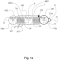
- FIG. 1a there is a second magnet 163 that is disposed within the center of the coil 1 and acts as a servant (magnetically coupled) magnet 163 that is free to rotate on its axles of rotation 5 ; and is under the mutual attractive combined magnetic field (static) MF1 that exists between the first magnet 161 and the second magnet 163.
- a servant magnet 163 that is disposed within the center of the coil 1 and acts as a servant (magnetically coupled) magnet 163 that is free to rotate on its axles of rotation 5 ; and is under the mutual attractive combined magnetic field (static) MF1 that exists between the first magnet 161 and the second magnet 163.
- FIG. 1a there is a third in-line servant (magnetically coupled) magnet 165 that is in a fixed position with its poles aligned so that its magnetic poles N3 and S3 are non-rotatable and fixed and aligned with the mutual attractive combined magnetic field MFC2 parallel to the horizontal plane between the third magnet 165 and the second magnet 163.
- a third in-line servant (magnetically coupled) magnet 165 that is in a fixed position with its poles aligned so that its magnetic poles N3 and S3 are non-rotatable and fixed and aligned with the mutual attractive combined magnetic field MFC2 parallel to the horizontal plane between the third magnet 165 and the second magnet 163.
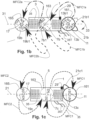
- FIG. 1b & FIG. 1c the basic in-line arrangement of three-cylinder magnets 161, 163, 165 is shown and in this embodiment, all three magnets are free to rotate on their respective axles of rotation 11, 5, 17.
- FIG. 1b shows the operation of changing movement states of the master control rotational magnet 9 when an external force is applied.
- FIG. 1a shows the no force applied state with the toggle paddle 21 and in this embodiment the toggle is at rest 21a in the horizontal plane 31.
- an external force a finger, moving object, lever from a trip-counter and any other foreign object offering an mechanical interference force to cause movement
- Another feature of this present invention is the mutual attractive magnetic field force (static MF1 (that exists between first master control magnet 161 that is rotatable and second magnet 163 in the role of servant [magnetically coupled] magnet 163 that is rotatable ) and the mutual attractive magnetic field force MF2 (that exists between second magnet 163 in the role of servant [magnetically coupled] magnet and third magnet 165 in the role of servant [magnetically coupled] magnet that is rotatable) that establishes a natural spring action eliminates any need for mechanical springs.
- static MF1 that exists between first master control magnet 161 that is rotatable and second magnet 163 in the role of servant [magnetically coupled] magnet 163 that is rotatable
- MF2 that exists between second magnet 163 in the role of servant [magnetically coupled] magnet and third magnet 165 in the role of servant [magnetically coupled] magnet that is rotatable
- a second mutual magnetic field (static) MF2 (at rest with no motion applied to any of the three in-line magnets) and this second mutual magnetic field MF2 is established with second acting as a servant (magnetically coupled) rotatable magnet 163 and third magnet 165 acting as a servant (magnetically coupled) rotatable magnet and its intrinsic residual magnetic field contributes in pairing attractive magnetic poles, by magnetic attraction of opposite magnetic poles, a second mutual magnetic field (static) MF2 (at rest with no motion applied to any of the three in-line magnets).
- FIG. 2a shows the mutual mechanical force Fm1 (measured in Newtons) that exists between the first magnet 161 ad second magnet 163 because of the magnetic attraction of the first and second magnets; and shows the mutual mechanical force Fm2 (measured in Newtons) that exists between the second magnet 163 and the third magnet 165 because of the attraction of the second and third magnets.
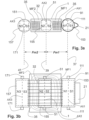
- FIG. 3b is a top view showing the in-line arrangement of the three-rotatable elongated rectangular bar magnets 153, 155, 157.
- First magnet 153 is disposed within its enclosure 91 and the enclosure has a set of axles in-line with the first magnet's imaginary reference axis AX1 where on each side of each of the three in-line magnets there exists three individual imaginary reference axis AX1 , AX2, & AX3, where there is the North Pole on one side of each magnet and the South Pole on the opposite side of each magnet; as shown in FIG. 3a & FIG. 3b .
- first master control rotatable magnet 153 disposed within its enclosure 91 with its intrinsic residual magnetic field contributes in pairing of attractive magnetic poles, by magnetic attraction of opposite magnetic poles, a first mutual magnetic field (static) MF1 (at rest with no motion applied to any of the three in-line magnets) and this first mutual magnetic field MF1 is established with first master control magnet 153 and second magnet 155 acting as a servant (magnetically coupled) rotatable magnet.
Landscapes
- Physics & Mathematics (AREA)
- Engineering & Computer Science (AREA)
- Power Engineering (AREA)
- Electromagnetism (AREA)
- Nonlinear Science (AREA)
- Electromagnets (AREA)
- Reciprocating, Oscillating Or Vibrating Motors (AREA)
- Control Of Eletrric Generators (AREA)
- Dynamo-Electric Clutches, Dynamo-Electric Brakes (AREA)
Claims (13)
- Generator, umfassend:eine Spule (1) mit einer Spulenwicklung (35) und Anschlussklemmen (35T);einen ausserhalb der Spule (1) und benachbart zu dieser angeordneten ersten Magnet (161; 153), der konfiguriert ist, auf einer ersten Rotationsachse (11; 111) zu rotieren;einen innerhalb der Spule (1) angeordneten zweiten Magneten (163; 155), der konfiguriert ist, auf einer zweiten Rotationsachse (5; 51) zu rotieren;einen ausserhalb der Spule (1) und benachbart zu dieser angeordneten dritten Magnet (165; 157), der konfiguriert ist, auf einer dritten Rotationsachse (17; 171) zu rotieren;wobei:der erste Magnet (161; 153), der zweite Magnet (163; 155), und der dritte Magnet (165; 157) auf einer gerade Linie in einer gemeinsamen horizontalen Ebene (31) angeordnet sind,der erste Magnet (161; 153), der zweite Magnet (163; 155) und der dritte Magnet (165; 157) jeweils einen magnetischen Nordpol und einen magnetischen Südpol hat;in einem Ruhezustand der erste Magnet (161; 153), der zweite Magnet (163; 155) magnetisch miteinander gekoppelt sind derart, dass der magnetische Nordpol des ersten Magnets (161; 153) dem magnetischen Südpol des zweite Magnets (163; 155) magnetisch anziehend gegenüberliegt, oder derart, dass der magnetische Südpol des ersten Magnets (161; 153) dem magnetischen Nordpol des zweiten Magnets (163; 155) magnetisch anziehend gegenüberliegt,in dem Ruhezustand der dritte Magnet (165; 157) und der zweite Magnet (163; 155) magnetisch miteinander gekoppelt sind derart, dass der magnetische Südpol des dritten Magnets (161; 153) dem magnetischen Nordpol des zweite Magnets (163; 155) magnetisch anziehend gegenüberliegt, oder derart, dass der magnetische Nordpol des dritten Magnets (165; 157) dem magnetischen Nordpol des zweiten Magnets (163; 155) magnetisch anziehend gegenüberliegt,und der erste Magnet (161; 153) ein Hauptsteuerungsmagnet ist derart, dass wenn er rotiert wird, gemeinsame magnetische Flusslinien, die vom ersten Magnet (161; 153), vom zweiten Magnet (163; 155) und vom dritten Magnet (165; 157) erzeugt werden und die Spulenwicklung (35) durchdringen, rechtwinklig zu der Spulenwicklung (35) ausgerichtet sind, wodurch eine Maximalspannung an den Anschlussklemmen (35T) hervorgerufen wird.
- Generator nach Anspruch 1, wobei der erste Magnet (161; 153) konfiguriert ist, in Reaktion auf eine ausgeübte Kraft zu rotieren.
- Generator nach Anspruch 2, wobei der erste Magnet (161; 153) in einem Gehäuse (9; 91) angeordnet ist, das einen Kippflügel (21) aufweist, der konfiguriert ist, die ausgeübte Kraft zu empfangen.
- Generator nach Anspruch 1, wobei die Spulenwicklung (35) auf einer Spulen-Bobine angeordnet ist.
- Generator nach Anspruch 1, wobei der dritte Magnet fixiert und nicht-rotierbar ist.
- Generator nach Anspruch 1, wobei der erste Magnet (161; 153) und der zweite Magnet (163; 155) jeweils in einem Gehäuse (9, 91; 3, 32) angeordnet ist.
- Generator nach Anspruch 1, weiterhin umfassend einen Hebel (191), der sowohl mit dem ersten Magnet (161) als auch mit dem zweiten Magnet (163) gekoppelt ist und konfiguriert ist, den zweiten Magnet (163) zu veranlassen, sich zusammen mit dem ersten Magnet (161) zu bewegen.
- Generator nach Anspruch 1, wobei der erste Magnet (161), der zweite Magnet (163) und der dritte Magnet (165) eine zylindrische Form haben.
- Generator nach Anspruch 1, wobei der erste Magnet (153), der zweite Magnet (155), und der dritte Magnet (15) eine rechteckige Form haben.
- Generator nach Anspruch 1, wobei zumindest einer von dem ersten, zweiten und dritten Magnet ein diametral gepolter Polygon-Magnet, ein axial gepolter Zylinder-Magnet oder ein axial gepolter Polygon-Magnet ist.
- Generator nach Anspruch 1, wobei der dritte Magnet konfiguriert ist, den ersten Magnet und den zweiten Magnet in einer verriegelten Position zu halten.
- Generator nach Anspruch 4, weiterhin umfassend eine zum Lagern der Spulen-Bobine konfigurierte Basisplatte (169).
- Generator nach Anspruch 12, wobei die Basisplatte (169) eine hohle Kammer (167) umfasst, und wobei der dritte Magnet (165) in der hohlen Kammer (167) angeordnet ist.
Priority Applications (1)
| Application Number | Priority Date | Filing Date | Title |
|---|---|---|---|
| EP24185918.0A EP4436017A3 (de) | 2017-10-30 | 2018-10-29 | Generator zur übertragung magnetischer momente |
Applications Claiming Priority (2)
| Application Number | Priority Date | Filing Date | Title |
|---|---|---|---|
| US201762578612P | 2017-10-30 | 2017-10-30 | |
| PCT/US2018/057957 WO2019089435A1 (en) | 2017-10-30 | 2018-10-29 | Magnetic momentum transfer generator |
Related Child Applications (1)
| Application Number | Title | Priority Date | Filing Date |
|---|---|---|---|
| EP24185918.0A Division EP4436017A3 (de) | 2017-10-30 | 2018-10-29 | Generator zur übertragung magnetischer momente |
Publications (4)
| Publication Number | Publication Date |
|---|---|
| EP3704785A1 EP3704785A1 (de) | 2020-09-09 |
| EP3704785A4 EP3704785A4 (de) | 2021-08-11 |
| EP3704785B1 true EP3704785B1 (de) | 2024-07-03 |
| EP3704785C0 EP3704785C0 (de) | 2024-07-03 |
Family
ID=66243192
Family Applications (2)
| Application Number | Title | Priority Date | Filing Date |
|---|---|---|---|
| EP18874872.7A Active EP3704785B1 (de) | 2017-10-30 | 2018-10-29 | Magnetimpulsübertragsgenerator |
| EP24185918.0A Withdrawn EP4436017A3 (de) | 2017-10-30 | 2018-10-29 | Generator zur übertragung magnetischer momente |
Family Applications After (1)
| Application Number | Title | Priority Date | Filing Date |
|---|---|---|---|
| EP24185918.0A Withdrawn EP4436017A3 (de) | 2017-10-30 | 2018-10-29 | Generator zur übertragung magnetischer momente |
Country Status (4)
| Country | Link |
|---|---|
| US (4) | US11251007B2 (de) |
| EP (2) | EP3704785B1 (de) |
| CN (1) | CN111819770B (de) |
| WO (1) | WO2019089435A1 (de) |
Families Citing this family (7)
| Publication number | Priority date | Publication date | Assignee | Title |
|---|---|---|---|---|
| US9343931B2 (en) | 2012-04-06 | 2016-05-17 | David Deak | Electrical generator with rotational gaussian surface magnet and stationary coil |
| US11251007B2 (en) | 2017-10-30 | 2022-02-15 | Wepower Technologies Llc | Magnetic momentum transfer generator |
| JP6651110B1 (ja) * | 2019-05-28 | 2020-02-19 | Dolphin株式会社 | 物体検出装置 |
| US11368079B2 (en) | 2019-11-06 | 2022-06-21 | David Deak, SR. | Offset triggered cantilever actuated generator |
| CN115053437A (zh) * | 2019-11-21 | 2022-09-13 | 威能科技有限责任公司 | 切向致动的磁动量传输发电机 |
| US11855505B2 (en) * | 2020-08-29 | 2023-12-26 | David Deak, SR. | Inline actuated horizontal pendulum energy harvesting generator and battery-free wireless remote switching system |
| FR3131657A1 (fr) * | 2021-12-30 | 2023-07-07 | Commissariat A L'energie Atomique Et Aux Energies Alternatives | Récuperateur d'energie a large gamme de vitesse de fonctionnement |
Family Cites Families (142)
| Publication number | Priority date | Publication date | Assignee | Title |
|---|---|---|---|---|
| US1711323A (en) | 1926-06-23 | 1929-04-30 | Richard A Oglesby | Oscillating magneto |
| US2703370A (en) * | 1952-07-02 | 1955-03-01 | Steensen Sverre Johan | Electric compressor or pump motor with rolling rotor |
| US3027499A (en) | 1957-10-23 | 1962-03-27 | Spoorweg Sein Ind N V | Electromagnetic system |
| DE1263174B (de) | 1964-10-13 | 1968-03-14 | Rheinmetall Gmbh | Stromstosserzeuger |
| US3218523A (en) | 1963-07-29 | 1965-11-16 | Benson Hector Eugene | Electromagnetic device having a permanent magnet armature |
| US3315104A (en) | 1964-04-16 | 1967-04-18 | Square D Co | Magnetic impulse generator |
| US3348080A (en) | 1965-06-07 | 1967-10-17 | Gen Dynamics Corp | Impulse generator |
| US3500082A (en) | 1967-08-15 | 1970-03-10 | Manuel J Tolegian | Drive unit for flexible shafts |
| US3671777A (en) | 1968-03-22 | 1972-06-20 | Mesur Matic Electronics Corp | Fast rise time pulse generator |
| US3621419A (en) | 1970-02-19 | 1971-11-16 | Leach Corp | Polarized latch relay |
| US3673999A (en) | 1970-08-24 | 1972-07-04 | Braun Anton | Electrical apparatus for initiating combustion in free piston engines |
| US3984707A (en) | 1973-07-13 | 1976-10-05 | Mcclintock Richard D | Spring return linear signal generator |
| US3895244A (en) | 1973-12-28 | 1975-07-15 | Norse Systems Inc | Encapsulated electromagnetic generator |
| US4187452A (en) | 1975-08-27 | 1980-02-05 | International Business Machines Corporation | Electromechanical torsional oscillator with resonant frequency and amplitude control |
| SE400385B (sv) | 1976-01-28 | 1978-03-20 | Nordstjernan Rederi Ab | Forfarande for att i ett svengande system i en metgivare avkenna systemets svengningstillstand samt anordning for genomforande av forfarandet |
| US4260901A (en) | 1979-02-26 | 1981-04-07 | Woodbridge David D | Wave operated electrical generation system |
| US4363980A (en) * | 1979-06-05 | 1982-12-14 | Polaroid Corporation | Linear motor |
| US4315197A (en) | 1980-02-07 | 1982-02-09 | The United States Of America As Represented By The Administrator Of The National Aeronautics And Space Administration | Linear magnetic motor/generator |
| US4870306A (en) * | 1981-10-08 | 1989-09-26 | Polaroid Corporation | Method and apparatus for precisely moving a motor armature |
| US4471353A (en) | 1981-10-14 | 1984-09-11 | Hughes Aircraft Company | Push-button switch for an electrical power source |
| US4412355A (en) | 1981-10-14 | 1983-10-25 | Hughes Aircraft Company | Push-button operated electrical power source for an optical communication link |
| DE3218181A1 (de) | 1982-05-14 | 1983-11-17 | Kuno Moser GmbH, Fabrik für Feinmechanik und Elektrotechnik, 7731 Unterkirnach | Schwingankerantrieb sowie verfahren zum betreiben eines schwingankerantriebes |
| CA1191535A (en) * | 1983-09-22 | 1985-08-06 | Leslie G. Meszaros | Rolling magnetic friction electricity generator |
| US4521712A (en) | 1983-11-25 | 1985-06-04 | United Technologies Automotive, Inc. | Pressure sensitive piezoelectric signal generator assembly |
| JPS61218035A (ja) | 1985-03-25 | 1986-09-27 | 松下電工株式会社 | 有極電磁石 |
| US4866321A (en) | 1985-03-26 | 1989-09-12 | William C. Lamb | Brushless electrical machine for use as motor or generator |
| US4855699A (en) * | 1988-03-11 | 1989-08-08 | Teledyne Microwave | Self-cutoff for latching coaxial switches |
| DE58904654D1 (de) | 1989-10-20 | 1993-07-15 | Siemens Ag | Induktiver bewegungssensor. |
| US5053659A (en) * | 1990-10-05 | 1991-10-01 | Denson Parker | Centrifugal force magnetic field variator |
| US5275141A (en) * | 1991-05-31 | 1994-01-04 | Asmo, Co., Ltd. | Actuator |
| US5204570A (en) | 1991-09-09 | 1993-04-20 | Gerfast Sten R | Spheroidal machine |
| WO1993017629A1 (en) | 1992-03-13 | 1993-09-16 | Alexander Gary E | Device for assisting childbirth |
| JPH07245052A (ja) | 1994-03-04 | 1995-09-19 | Omron Corp | 電磁石装置 |
| US5808381A (en) * | 1994-08-09 | 1998-09-15 | Hitachi Metals, Ltd. | Linear motor |
| GB9505045D0 (en) | 1995-03-13 | 1995-05-03 | Ashley & Rock Ltd | Electric switch |
| JPH08322226A (ja) | 1995-03-20 | 1996-12-03 | Asmo Co Ltd | ロータリアクチュエータ |
| JPH08275498A (ja) * | 1995-03-31 | 1996-10-18 | Minolta Co Ltd | リニアモータ |
| US5913091A (en) * | 1996-05-21 | 1999-06-15 | Minolta Co., Ltd. | Image reading apparatus |
| US20010052413A1 (en) | 1997-09-26 | 2001-12-20 | Raj Mahadevaiah | Method and apparatus for extracting hydrophobic napl |
| WO1999019962A1 (en) * | 1997-10-16 | 1999-04-22 | Omnidyne Inc. | Generators and transformers with toroidally wound stator winding |
| US6331744B1 (en) | 1998-02-10 | 2001-12-18 | Light Sciences Corporation | Contactless energy transfer apparatus |
| JPH11264368A (ja) | 1998-03-17 | 1999-09-28 | Yukio Hirata | 2重ラック4軸磁石エンジン |
| KR100286010B1 (ko) | 1998-03-31 | 2001-04-16 | 김덕용 | 자화된로커를이용한스위치 |
| CA2328887A1 (en) | 1998-04-23 | 1999-10-28 | Omnific International, Ltd. | Specialized actuators driven by oscillatory transducers |
| US7021603B2 (en) * | 1998-10-08 | 2006-04-04 | Wladyslaw Wygnaski | Electromagnetic actuator and integrated actuator and fluid flow control valve |
| US6259372B1 (en) | 1999-01-22 | 2001-07-10 | Eaton Corporation | Self-powered wireless transducer |
| IL132043A0 (en) | 1999-09-23 | 2001-03-19 | Baran Advanced Tech Ltd | A continuous switch employing a pressure-sensitive element |
| US6326714B1 (en) | 1999-10-27 | 2001-12-04 | Moog Inc. | Two-axis pointing motor |
| FR2802731B1 (fr) | 1999-12-16 | 2002-01-25 | Schneider Electric Ind Sa | Dispositif autonome de commande a distance, appareil et installation electrique comportant un tel dispositif |
| US6630894B1 (en) | 2000-07-14 | 2003-10-07 | Face International Corp. | Self-powered switching device |
| US6700310B2 (en) | 2000-10-13 | 2004-03-02 | Lear Corporation | Self-powered wireless switch |
| DE10054862A1 (de) | 2000-11-06 | 2002-06-13 | Dyna Systems Gmbh | Elektrischer Schalter, insbesondere Piezoschalter, mit optischer und/oder mechanischer Rückmeldung des Schaltvorganges |
| US20020070712A1 (en) | 2000-12-13 | 2002-06-13 | Arul Senthil G. | Hand-held remote-control device with high-capacitance power supply |
| US20020130561A1 (en) | 2001-03-18 | 2002-09-19 | Temesvary Viktoria A. | Moving coil motor and implementations in MEMS based optical switches |
| EP1376833A4 (de) * | 2001-03-27 | 2011-08-10 | Panasonic Elec Works Co Ltd | Linearoszillator und elektrisch angetriebene zahnbürste |
| TW521473B (en) | 2001-06-05 | 2003-02-21 | Hiwin Mikrosystem Corp | Secondary structure of linear stepping motor and the manufacturing method thereof |
| US6720682B2 (en) | 2001-06-14 | 2004-04-13 | Lightbay Networks Corporation | Actuator assembly for tilting a mirror or like object |
| FR2828000B1 (fr) * | 2001-07-27 | 2003-12-05 | Commissariat Energie Atomique | Actionneur magnetique a aimant mobile |
| US6812583B2 (en) * | 2002-02-19 | 2004-11-02 | Rockwell Scientific Licensing, Llc | Electrical generator with ferrofluid bearings |
| US7081693B2 (en) | 2002-03-07 | 2006-07-25 | Microstrain, Inc. | Energy harvesting for wireless sensor operation and data transmission |
| US6798090B2 (en) | 2002-04-18 | 2004-09-28 | Rockwell Scientific Licensing, Llc | Electrical power generation by coupled magnets |
| KR100938197B1 (ko) * | 2002-05-23 | 2010-01-21 | 순옌 컴퍼니, 리미티드 | 구동력을 자가 발생시키는 장치 |
| JP2004151669A (ja) | 2002-09-05 | 2004-05-27 | Citizen Watch Co Ltd | アクチュエータ装置 |
| JP2004112849A (ja) | 2002-09-13 | 2004-04-08 | Honda Motor Co Ltd | 永久磁石型回転子 |
| US20040174287A1 (en) | 2002-11-21 | 2004-09-09 | Deak David G. | Self-contained switch |
| US6879076B2 (en) * | 2002-12-09 | 2005-04-12 | Johnny D. Long | Ellipsoid generator |
| DE10302236B4 (de) | 2003-01-20 | 2012-12-06 | Zf Friedrichshafen Ag | Reibungskupplung oder Reibungsbremse mit Selbstverstärkung |
| FR2852162B1 (fr) | 2003-03-06 | 2005-09-23 | Leroy Somer Moteurs | Machine electrique tournante comportant un stator et deux rotors |
| DE10315765C5 (de) | 2003-04-07 | 2021-03-11 | Enocean Gmbh | Verwendung eines elektromagnetischen Energiewandlers |
| US6960848B2 (en) * | 2003-05-09 | 2005-11-01 | Nisca Corporation | Electromagnetic drive device and light quantity adjustment device using the same |
| TWM244935U (en) | 2003-07-11 | 2004-10-01 | Kuen-Tsai Shen | Manual power generator |
| US7242118B2 (en) * | 2003-07-31 | 2007-07-10 | Japan Servo Co., Ltd. | Toroidal-coil linear stepping motor, toroidal-coil linear reciprocating motor, cylinder compressor and cylinder pump using these motors |
| WO2005041464A2 (en) | 2003-10-24 | 2005-05-06 | Face Bradbury R | Self-powered, electronic keyed, multifunction switching system |
| WO2005124979A1 (ja) * | 2004-06-21 | 2005-12-29 | Konica Minolta Medical & Graphic, Inc. | リニアモータ及びリニアモータの製造方法 |
| US7378765B2 (en) * | 2004-08-09 | 2008-05-27 | Oriental Motor Co., Ltd. | Cylinder-type linear motor and moving part thereof |
| US7333783B2 (en) | 2005-04-14 | 2008-02-19 | Teledyne Licensing, Llc | Mobile device with manually operated power source |
| US20060237968A1 (en) * | 2005-04-20 | 2006-10-26 | Rockwell Scientific Licensing, Llc | High efficiency power converter for energy harvesting devices |
| US7151332B2 (en) | 2005-04-27 | 2006-12-19 | Stephen Kundel | Motor having reciprocating and rotating permanent magnets |
| JP4546894B2 (ja) * | 2005-08-04 | 2010-09-22 | 富士通コンポーネント株式会社 | 触覚情報提示用アクチュエータ |
| US7026900B1 (en) | 2005-09-22 | 2006-04-11 | John Gregory | Magnetic motion device |
| FR2893780A1 (fr) | 2005-11-22 | 2007-05-25 | Schneider Electric Ind Sas | Dispositif autonome de generation d'energie electrique |
| DE102006013237B4 (de) | 2006-03-22 | 2011-01-13 | Hahn-Schickard-Gesellschaft für angewandte Forschung e.V. | Mechanisch-Elektrischer Generator |
| US7688036B2 (en) | 2006-06-26 | 2010-03-30 | Battelle Energy Alliance, Llc | System and method for storing energy |
| WO2008019054A2 (en) | 2006-08-03 | 2008-02-14 | Deak David G | Electromotive device |
| JP5100073B2 (ja) * | 2006-09-28 | 2012-12-19 | 村田機械株式会社 | リニアモータ装置およびそれを搭載した工作機械 |
| ATE549785T1 (de) | 2006-12-21 | 2012-03-15 | Saab Ab | Ampg-vorrichtung zur stromerzeugung aus schwingungen, ampg-vorrichtungsanordnung sowie verfahren zur optimierung besagter stromerzeugung |
| US7436082B2 (en) | 2007-01-24 | 2008-10-14 | Itt Manufacturing Enterprises, Inc. | Rocking motion charging device using faraday principle |
| US8633604B2 (en) | 2007-02-19 | 2014-01-21 | Michael Miller | Engine |
| US8539765B2 (en) | 2007-02-19 | 2013-09-24 | Michael Miller | Engine |
| JP5224209B2 (ja) | 2007-03-02 | 2013-07-03 | 孝仁 今川 | 二次元共鳴振動モーター |
| EP2178738B1 (de) | 2007-07-30 | 2011-04-06 | Reelight APS | Fahrraddynamo |
| DE102008003595B4 (de) | 2008-01-09 | 2009-10-08 | Panasonic Electric Works Europe Ag | Energiewandler |
| WO2009100022A2 (en) | 2008-02-01 | 2009-08-13 | University Of Florida Research Foundation, Inc. | A method and apparatus for motional/vibrational energy harvesting via electromagnetic induction |
| JP4415133B2 (ja) * | 2008-02-07 | 2010-02-17 | 隆逸 小林 | リニア発電装置 |
| JP2009261204A (ja) | 2008-04-14 | 2009-11-05 | Fukuichi Yuki | ロール形発電機 |
| PT104442A (pt) | 2009-03-16 | 2010-09-16 | Pedro Da Costa Balas Ferreira | Gerador eléctrico esférico de indução magnética |
| ES2377656B1 (es) | 2009-06-16 | 2013-02-06 | Consejo Superior De Investigaciones Científicas (Csic) | Dispositivo para generar energía eléctrica a partir de pequeños movimientos. |
| US20110001381A1 (en) | 2009-07-06 | 2011-01-06 | Mcdaniel Scott L | McDaniel magnet motor |
| DK200900829A (en) | 2009-07-06 | 2009-07-13 | Col Holding Aps | A bicycle lamp |
| CN201490855U (zh) | 2009-08-17 | 2010-05-26 | 江源 | 多转子永磁发电机 |
| US8816557B2 (en) | 2009-11-06 | 2014-08-26 | Electric Gorilla, LLC | Dynamoelectric device |
| US8242660B2 (en) | 2009-11-16 | 2012-08-14 | G+ Powertec Ltd. | AC generator |
| FR2953659B1 (fr) * | 2009-12-04 | 2011-12-23 | Schneider Electric Ind Sas | Dispositif generateur d'energie electrique et telecommande pourvue d'un tel dispositif |
| FR2953658B1 (fr) | 2009-12-08 | 2011-12-30 | Commissariat Energie Atomique | Alternateur et systeme electrique correspondant |
| US8330283B2 (en) | 2010-03-22 | 2012-12-11 | Ming-Sheng Lin | Underground generating device that is rolled or run over by cars so as to provide a generating effect |
| DE102010003151A1 (de) | 2010-03-23 | 2011-09-29 | Zf Friedrichshafen Ag | Induktionsgenerator |
| CA2873488C (en) | 2010-04-15 | 2019-04-02 | Hanchett Entry Systems, Inc. | Electromagnetic energy harvester and a door latch release mechanism as an energy source for the harvester |
| DE102010017874B4 (de) | 2010-04-21 | 2013-09-05 | Saia-Burgess Dresden Gmbh | Bistabiler Magnetaktor |
| GB2479926B (en) | 2010-04-30 | 2016-05-11 | Atherton Nigel | Electricity generator |
| US8299659B1 (en) | 2010-08-14 | 2012-10-30 | Bartol Jr Robert J | Electric power generator apparatus |
| US8514040B2 (en) | 2011-02-11 | 2013-08-20 | Clodi, L.L.C. | Bi-stable electromagnetic relay with x-drive motor |
| JP5637028B2 (ja) * | 2011-03-22 | 2014-12-10 | スミダコーポレーション株式会社 | 振動発電機 |
| US8907505B2 (en) | 2011-08-03 | 2014-12-09 | Energy Harvesters Llc | Method and apparatus for generating electrical energy |
| WO2013031127A1 (ja) | 2011-08-29 | 2013-03-07 | パナソニック株式会社 | 発電装置 |
| WO2013035057A2 (en) | 2011-09-06 | 2013-03-14 | Kocain Industries S.R.L. | Electric generator and method for producing electrical energy |
| CN107196453B (zh) | 2012-02-08 | 2019-06-28 | 日本精工株式会社 | 驱动器、定子、马达、旋转直线运动转换机构以及线性运动驱动器 |
| CN103295847B (zh) | 2012-03-01 | 2016-12-07 | 德昌电机(深圳)有限公司 | 驱动装置及具有该驱动装置的继电器 |
| US9343931B2 (en) | 2012-04-06 | 2016-05-17 | David Deak | Electrical generator with rotational gaussian surface magnet and stationary coil |
| JP5824647B2 (ja) | 2012-10-18 | 2015-11-25 | パナソニックIpマネジメント株式会社 | 発電装置 |
| US8629572B1 (en) | 2012-10-29 | 2014-01-14 | Reed E. Phillips | Linear faraday induction generator for the generation of electrical power from ocean wave kinetic energy and arrangements thereof |
| US20140215693A1 (en) | 2013-02-07 | 2014-08-07 | Gregory J. O'Gara | Helmet systems and other wearable safety gear |
| US20140246960A1 (en) | 2013-03-04 | 2014-09-04 | Stephen Smith | Energy transfer system and method |
| CN203166718U (zh) | 2013-04-16 | 2013-08-28 | 慈溪宝诚知识产权服务有限公司 | 一种节能发电机 |
| US20150091479A1 (en) | 2013-10-01 | 2015-04-02 | Jonathan David L. Spivak | Electric Vehicle Propulsion System Using Magnetic Piston Engine |
| US20150091395A1 (en) * | 2013-10-01 | 2015-04-02 | Jonathan David L. Spivak | Electro-mechanical Reciprocating Magnetic Piston Engine |
| EP3059850A4 (de) | 2013-10-14 | 2017-06-07 | Sunrising Eco-Friendly Tech. Co., Ltd. | Mobile induktions- und stromerzeugungsvorrichtung |
| US9543817B2 (en) | 2014-06-07 | 2017-01-10 | David Deak, SR. | Hollow magnetic metal core pulse energy harvesting generator |
| US9673683B2 (en) | 2014-11-07 | 2017-06-06 | David Deak, SR. | Reciprocating magnet electrical generator |
| US10523098B1 (en) * | 2014-12-01 | 2019-12-31 | Dale Bowen | Progressive magnetic rotation motor |
| US9843248B2 (en) | 2015-06-04 | 2017-12-12 | David Deak, SR. | Rocker action electric generator |
| JP6893306B2 (ja) | 2015-10-20 | 2021-06-23 | リニア ラブズ リミテッド ライアビリティ カンパニー | 磁場弱め機構を備える円周磁束電気機械及びその使用方法 |
| PL3378145T3 (pl) * | 2015-11-17 | 2020-12-14 | Tuangsin PUREEPASWONG | Generator prądu elektrycznego z funkcją unikania oporu obrotowego |
| US20170346377A1 (en) | 2016-05-25 | 2017-11-30 | David Deak, SR. | Tangentially actuated electrical generator |
| US11660403B2 (en) | 2016-09-22 | 2023-05-30 | Juul Labs, Inc. | Leak-resistant vaporizer device |
| US10348160B2 (en) | 2016-11-22 | 2019-07-09 | Generen, Inc. | Rotationally activated generator |
| US10396642B2 (en) * | 2017-02-28 | 2019-08-27 | Allen Petrick | Magnetic propulsion and electrical generation system |
| CN106992649B (zh) | 2017-05-27 | 2019-01-18 | 江西理工大学 | 变磁通永磁能量转换设备 |
| US11251007B2 (en) | 2017-10-30 | 2022-02-15 | Wepower Technologies Llc | Magnetic momentum transfer generator |
| US10855158B2 (en) | 2018-04-19 | 2020-12-01 | Watasensor, Inc. | Magnetic power generation |
| TWI665852B (zh) * | 2018-06-26 | 2019-07-11 | 魅克司股份有限公司 | 磁性轉盤 |
| US11368079B2 (en) | 2019-11-06 | 2022-06-21 | David Deak, SR. | Offset triggered cantilever actuated generator |
| CN115053437A (zh) | 2019-11-21 | 2022-09-13 | 威能科技有限责任公司 | 切向致动的磁动量传输发电机 |
-
2018
- 2018-10-29 US US16/173,341 patent/US11251007B2/en active Active
- 2018-10-29 EP EP18874872.7A patent/EP3704785B1/de active Active
- 2018-10-29 CN CN201880080434.3A patent/CN111819770B/zh active Active
- 2018-10-29 WO PCT/US2018/057957 patent/WO2019089435A1/en not_active Ceased
- 2018-10-29 EP EP24185918.0A patent/EP4436017A3/de not_active Withdrawn
-
2021
- 2021-07-26 US US17/443,418 patent/US11915898B2/en active Active
-
2024
- 2024-01-23 US US18/419,824 patent/US12505969B2/en active Active
-
2025
- 2025-12-12 US US19/418,359 patent/US20260100321A1/en active Pending
Also Published As
| Publication number | Publication date |
|---|---|
| US20260100321A1 (en) | 2026-04-09 |
| US12505969B2 (en) | 2025-12-23 |
| EP3704785A4 (de) | 2021-08-11 |
| US20190131098A1 (en) | 2019-05-02 |
| US20220020550A1 (en) | 2022-01-20 |
| EP4436017A2 (de) | 2024-09-25 |
| US11915898B2 (en) | 2024-02-27 |
| CN111819770A (zh) | 2020-10-23 |
| EP4436017A3 (de) | 2024-12-25 |
| EP3704785C0 (de) | 2024-07-03 |
| WO2019089435A1 (en) | 2019-05-09 |
| US11251007B2 (en) | 2022-02-15 |
| CN111819770B (zh) | 2023-09-19 |
| US20240363300A1 (en) | 2024-10-31 |
| EP3704785A1 (de) | 2020-09-09 |
Similar Documents
| Publication | Publication Date | Title |
|---|---|---|
| US12505969B2 (en) | Magnetic momentum transfer generator | |
| US9768674B2 (en) | Printed-circuit board coil and motor | |
| US12323022B2 (en) | Tangentially actuated magnetic momentum transfer generator | |
| US20100048980A1 (en) | Electro-mechanical massage device and wearable massage apparatus | |
| JP2008048597A (ja) | 線形振動子 | |
| US20170346377A1 (en) | Tangentially actuated electrical generator | |
| US12095333B2 (en) | Vibrational energy harvester | |
| KR101286471B1 (ko) | 진동발생 모듈, 이를 이용한 액추에이터, 및 휴대용 기기 | |
| KR101224432B1 (ko) | 진동발생 모듈, 이를 이용한 액추에이터, 및 휴대용 기기 | |
| WO2015015523A1 (en) | Self-powered mouse equipped with magnetic-mechanical harvester device for generating electricity | |
| JP2004112937A (ja) | 磁気アクチュエータ及び触覚呈示装置 | |
| KR100939801B1 (ko) | 솔레노이드 | |
| US3518497A (en) | Bistable polarized interrupter with remote control and respective system of utilization | |
| US7495536B2 (en) | Magnetic actuator for direct generation of a rotary actuation of a shaft with currentless fixation of the stop position | |
| FI119791B (fi) | Lineaarigeneraattori | |
| RU2548672C1 (ru) | Генератор (варианты) | |
| KR101961108B1 (ko) | 발전장치 및 그 제어 방법 | |
| JP2014187798A (ja) | エネルギ変換装置 | |
| JP7117838B2 (ja) | 振動発電機 | |
| KR101356765B1 (ko) | 리니어 액추에이터 | |
| KR20140029611A (ko) | 자기장을 활용한 에너지 | |
| Woo | Magnetic Field | |
| Shoffa et al. | Miniature contact detector of magnetic field singuular points distribution for use under designing of electromechanical devices structure | |
| KR20140022126A (ko) | 자기장의 활용 |
Legal Events
| Date | Code | Title | Description |
|---|---|---|---|
| STAA | Information on the status of an ep patent application or granted ep patent |
Free format text: STATUS: THE INTERNATIONAL PUBLICATION HAS BEEN MADE |
|
| PUAI | Public reference made under article 153(3) epc to a published international application that has entered the european phase |
Free format text: ORIGINAL CODE: 0009012 |
|
| STAA | Information on the status of an ep patent application or granted ep patent |
Free format text: STATUS: REQUEST FOR EXAMINATION WAS MADE |
|
| 17P | Request for examination filed |
Effective date: 20200528 |
|
| AK | Designated contracting states |
Kind code of ref document: A1 Designated state(s): AL AT BE BG CH CY CZ DE DK EE ES FI FR GB GR HR HU IE IS IT LI LT LU LV MC MK MT NL NO PL PT RO RS SE SI SK SM TR |
|
| AX | Request for extension of the european patent |
Extension state: BA ME |
|
| RAP1 | Party data changed (applicant data changed or rights of an application transferred) |
Owner name: WEPOWER TECHNOLOGIES LLC |
|
| RIN1 | Information on inventor provided before grant (corrected) |
Inventor name: DEAK, DAVID SR. |
|
| DAV | Request for validation of the european patent (deleted) | ||
| DAX | Request for extension of the european patent (deleted) | ||
| A4 | Supplementary search report drawn up and despatched |
Effective date: 20210708 |
|
| RIC1 | Information provided on ipc code assigned before grant |
Ipc: H03K 3/45 20060101AFI20210702BHEP Ipc: H02K 16/02 20060101ALI20210702BHEP Ipc: H02K 21/12 20060101ALI20210702BHEP |
|
| REG | Reference to a national code |
Ref country code: DE Ref legal event code: R079 Free format text: PREVIOUS MAIN CLASS: H02K0007180000 Ipc: H03K0003450000 Ref document number: 602018071417 Country of ref document: DE |
|
| GRAP | Despatch of communication of intention to grant a patent |
Free format text: ORIGINAL CODE: EPIDOSNIGR1 |
|
| STAA | Information on the status of an ep patent application or granted ep patent |
Free format text: STATUS: GRANT OF PATENT IS INTENDED |
|
| RIC1 | Information provided on ipc code assigned before grant |
Ipc: H02K 21/12 20060101ALI20231222BHEP Ipc: H02K 16/02 20060101ALI20231222BHEP Ipc: H03K 3/45 20060101AFI20231222BHEP |
|
| INTG | Intention to grant announced |
Effective date: 20240124 |
|
| GRAS | Grant fee paid |
Free format text: ORIGINAL CODE: EPIDOSNIGR3 |
|
| GRAA | (expected) grant |
Free format text: ORIGINAL CODE: 0009210 |
|
| STAA | Information on the status of an ep patent application or granted ep patent |
Free format text: STATUS: THE PATENT HAS BEEN GRANTED |
|
| AK | Designated contracting states |
Kind code of ref document: B1 Designated state(s): AL AT BE BG CH CY CZ DE DK EE ES FI FR GB GR HR HU IE IS IT LI LT LU LV MC MK MT NL NO PL PT RO RS SE SI SK SM TR |
|
| REG | Reference to a national code |
Ref country code: CH Ref legal event code: EP |
|
| REG | Reference to a national code |
Ref country code: DE Ref legal event code: R096 Ref document number: 602018071417 Country of ref document: DE |
|
| U01 | Request for unitary effect filed |
Effective date: 20240725 |
|
| U07 | Unitary effect registered |
Designated state(s): AT BE BG DE DK EE FI FR IT LT LU LV MT NL PT RO SE SI Effective date: 20240902 |
|
| U20 | Renewal fee for the european patent with unitary effect paid |
Year of fee payment: 7 Effective date: 20240906 |
|
| PG25 | Lapsed in a contracting state [announced via postgrant information from national office to epo] |
Ref country code: NO Free format text: LAPSE BECAUSE OF FAILURE TO SUBMIT A TRANSLATION OF THE DESCRIPTION OR TO PAY THE FEE WITHIN THE PRESCRIBED TIME-LIMIT Effective date: 20241003 |
|
| PG25 | Lapsed in a contracting state [announced via postgrant information from national office to epo] |
Ref country code: GR Free format text: LAPSE BECAUSE OF FAILURE TO SUBMIT A TRANSLATION OF THE DESCRIPTION OR TO PAY THE FEE WITHIN THE PRESCRIBED TIME-LIMIT Effective date: 20241004 Ref country code: PL Free format text: LAPSE BECAUSE OF FAILURE TO SUBMIT A TRANSLATION OF THE DESCRIPTION OR TO PAY THE FEE WITHIN THE PRESCRIBED TIME-LIMIT Effective date: 20240703 |
|
| PG25 | Lapsed in a contracting state [announced via postgrant information from national office to epo] |
Ref country code: IS Free format text: LAPSE BECAUSE OF FAILURE TO SUBMIT A TRANSLATION OF THE DESCRIPTION OR TO PAY THE FEE WITHIN THE PRESCRIBED TIME-LIMIT Effective date: 20241103 |
|
| PG25 | Lapsed in a contracting state [announced via postgrant information from national office to epo] |
Ref country code: CZ Free format text: LAPSE BECAUSE OF FAILURE TO SUBMIT A TRANSLATION OF THE DESCRIPTION OR TO PAY THE FEE WITHIN THE PRESCRIBED TIME-LIMIT Effective date: 20240703 Ref country code: HR Free format text: LAPSE BECAUSE OF FAILURE TO SUBMIT A TRANSLATION OF THE DESCRIPTION OR TO PAY THE FEE WITHIN THE PRESCRIBED TIME-LIMIT Effective date: 20240703 |
|
| PG25 | Lapsed in a contracting state [announced via postgrant information from national office to epo] |
Ref country code: RS Free format text: LAPSE BECAUSE OF FAILURE TO SUBMIT A TRANSLATION OF THE DESCRIPTION OR TO PAY THE FEE WITHIN THE PRESCRIBED TIME-LIMIT Effective date: 20241003 Ref country code: ES Free format text: LAPSE BECAUSE OF FAILURE TO SUBMIT A TRANSLATION OF THE DESCRIPTION OR TO PAY THE FEE WITHIN THE PRESCRIBED TIME-LIMIT Effective date: 20240703 |
|
| PG25 | Lapsed in a contracting state [announced via postgrant information from national office to epo] |
Ref country code: RS Free format text: LAPSE BECAUSE OF FAILURE TO SUBMIT A TRANSLATION OF THE DESCRIPTION OR TO PAY THE FEE WITHIN THE PRESCRIBED TIME-LIMIT Effective date: 20241003 Ref country code: PL Free format text: LAPSE BECAUSE OF FAILURE TO SUBMIT A TRANSLATION OF THE DESCRIPTION OR TO PAY THE FEE WITHIN THE PRESCRIBED TIME-LIMIT Effective date: 20240703 Ref country code: NO Free format text: LAPSE BECAUSE OF FAILURE TO SUBMIT A TRANSLATION OF THE DESCRIPTION OR TO PAY THE FEE WITHIN THE PRESCRIBED TIME-LIMIT Effective date: 20241003 Ref country code: IS Free format text: LAPSE BECAUSE OF FAILURE TO SUBMIT A TRANSLATION OF THE DESCRIPTION OR TO PAY THE FEE WITHIN THE PRESCRIBED TIME-LIMIT Effective date: 20241103 Ref country code: HR Free format text: LAPSE BECAUSE OF FAILURE TO SUBMIT A TRANSLATION OF THE DESCRIPTION OR TO PAY THE FEE WITHIN THE PRESCRIBED TIME-LIMIT Effective date: 20240703 Ref country code: GR Free format text: LAPSE BECAUSE OF FAILURE TO SUBMIT A TRANSLATION OF THE DESCRIPTION OR TO PAY THE FEE WITHIN THE PRESCRIBED TIME-LIMIT Effective date: 20241004 Ref country code: ES Free format text: LAPSE BECAUSE OF FAILURE TO SUBMIT A TRANSLATION OF THE DESCRIPTION OR TO PAY THE FEE WITHIN THE PRESCRIBED TIME-LIMIT Effective date: 20240703 Ref country code: CZ Free format text: LAPSE BECAUSE OF FAILURE TO SUBMIT A TRANSLATION OF THE DESCRIPTION OR TO PAY THE FEE WITHIN THE PRESCRIBED TIME-LIMIT Effective date: 20240703 |
|
| PG25 | Lapsed in a contracting state [announced via postgrant information from national office to epo] |
Ref country code: SM Free format text: LAPSE BECAUSE OF FAILURE TO SUBMIT A TRANSLATION OF THE DESCRIPTION OR TO PAY THE FEE WITHIN THE PRESCRIBED TIME-LIMIT Effective date: 20240703 |
|
| PG25 | Lapsed in a contracting state [announced via postgrant information from national office to epo] |
Ref country code: SK Free format text: LAPSE BECAUSE OF FAILURE TO SUBMIT A TRANSLATION OF THE DESCRIPTION OR TO PAY THE FEE WITHIN THE PRESCRIBED TIME-LIMIT Effective date: 20240703 |
|
| PLBE | No opposition filed within time limit |
Free format text: ORIGINAL CODE: 0009261 |
|
| STAA | Information on the status of an ep patent application or granted ep patent |
Free format text: STATUS: NO OPPOSITION FILED WITHIN TIME LIMIT |
|
| REG | Reference to a national code |
Ref country code: CH Ref legal event code: PL |
|
| 26N | No opposition filed |
Effective date: 20250404 |
|
| PG25 | Lapsed in a contracting state [announced via postgrant information from national office to epo] |
Ref country code: MC Free format text: LAPSE BECAUSE OF FAILURE TO SUBMIT A TRANSLATION OF THE DESCRIPTION OR TO PAY THE FEE WITHIN THE PRESCRIBED TIME-LIMIT Effective date: 20240703 |
|
| PG25 | Lapsed in a contracting state [announced via postgrant information from national office to epo] |
Ref country code: CH Free format text: LAPSE BECAUSE OF NON-PAYMENT OF DUE FEES Effective date: 20241031 |
|
| U20 | Renewal fee for the european patent with unitary effect paid |
Year of fee payment: 8 Effective date: 20250909 |
|
| PGFP | Annual fee paid to national office [announced via postgrant information from national office to epo] |
Ref country code: GB Payment date: 20250904 Year of fee payment: 8 |
|
| PG25 | Lapsed in a contracting state [announced via postgrant information from national office to epo] |
Ref country code: IE Free format text: LAPSE BECAUSE OF NON-PAYMENT OF DUE FEES Effective date: 20241029 |
|
| PG25 | Lapsed in a contracting state [announced via postgrant information from national office to epo] |
Ref country code: HU Free format text: LAPSE BECAUSE OF FAILURE TO SUBMIT A TRANSLATION OF THE DESCRIPTION OR TO PAY THE FEE WITHIN THE PRESCRIBED TIME-LIMIT; INVALID AB INITIO Effective date: 20181029 |
|
| PG25 | Lapsed in a contracting state [announced via postgrant information from national office to epo] |
Ref country code: CY Free format text: LAPSE BECAUSE OF FAILURE TO SUBMIT A TRANSLATION OF THE DESCRIPTION OR TO PAY THE FEE WITHIN THE PRESCRIBED TIME-LIMIT; INVALID AB INITIO Effective date: 20181029 |