EP3705404B1 - Verbindungsvorrichtung zwischen einem luftfahrzeugmotor und einer primärstruktur eines luftfahrzeugmasts, die ein seitensteuerpedal und ein system für die begrenzung des ruderausschlags ausserhalb der ebene umfasst, und eine solche verbindungsvorrichtung umfassendes luftfahrzeug - Google Patents
Verbindungsvorrichtung zwischen einem luftfahrzeugmotor und einer primärstruktur eines luftfahrzeugmasts, die ein seitensteuerpedal und ein system für die begrenzung des ruderausschlags ausserhalb der ebene umfasst, und eine solche verbindungsvorrichtung umfassendes luftfahrzeug Download PDFInfo
- Publication number
- EP3705404B1 EP3705404B1 EP20157992.7A EP20157992A EP3705404B1 EP 3705404 B1 EP3705404 B1 EP 3705404B1 EP 20157992 A EP20157992 A EP 20157992A EP 3705404 B1 EP3705404 B1 EP 3705404B1
- Authority
- EP
- European Patent Office
- Prior art keywords
- fitting
- linking device
- face
- branch
- aircraft
- Prior art date
- Legal status (The legal status is an assumption and is not a legal conclusion. Google has not performed a legal analysis and makes no representation as to the accuracy of the status listed.)
- Active
Links
Images



Classifications
-
- B—PERFORMING OPERATIONS; TRANSPORTING
- B64—AIRCRAFT; AVIATION; COSMONAUTICS
- B64D—EQUIPMENT FOR FITTING IN OR TO AIRCRAFT; FLIGHT SUITS; PARACHUTES; ARRANGEMENT OR MOUNTING OF POWER PLANTS OR PROPULSION TRANSMISSIONS IN AIRCRAFT
- B64D27/00—Arrangement or mounting of power plants in aircraft; Aircraft characterised by the type or position of power plants
- B64D27/40—Arrangements for mounting power plants in aircraft
- B64D27/406—Suspension arrangements specially adapted for supporting thrust loads, e.g. thrust links
-
- B—PERFORMING OPERATIONS; TRANSPORTING
- B64—AIRCRAFT; AVIATION; COSMONAUTICS
- B64D—EQUIPMENT FOR FITTING IN OR TO AIRCRAFT; FLIGHT SUITS; PARACHUTES; ARRANGEMENT OR MOUNTING OF POWER PLANTS OR PROPULSION TRANSMISSIONS IN AIRCRAFT
- B64D27/00—Arrangement or mounting of power plants in aircraft; Aircraft characterised by the type or position of power plants
- B64D27/02—Aircraft characterised by the type or position of power plants
- B64D27/16—Aircraft characterised by the type or position of power plants of jet type
- B64D27/18—Aircraft characterised by the type or position of power plants of jet type within, or attached to, wings
-
- B—PERFORMING OPERATIONS; TRANSPORTING
- B64—AIRCRAFT; AVIATION; COSMONAUTICS
- B64D—EQUIPMENT FOR FITTING IN OR TO AIRCRAFT; FLIGHT SUITS; PARACHUTES; ARRANGEMENT OR MOUNTING OF POWER PLANTS OR PROPULSION TRANSMISSIONS IN AIRCRAFT
- B64D27/00—Arrangement or mounting of power plants in aircraft; Aircraft characterised by the type or position of power plants
- B64D27/40—Arrangements for mounting power plants in aircraft
- B64D27/404—Suspension arrangements specially adapted for supporting vertical loads
Definitions
- the present application relates to a connecting device connecting an aircraft engine and a primary structure of an aircraft mast comprising a rudder bar and a system for limiting the out-of-plane travel of the rudder bar as well as to an aircraft comprising such a linkage device.
- US 5,320,307 discloses a connecting device connecting an aircraft engine and a primary structure of an aircraft mast which forms part of the state of the art.
- an aircraft 10 comprises several propulsion assemblies 12 positioned under each of the wings 14 of the aircraft.
- Each propulsion unit 12 comprises an engine 16, a nacelle (not shown in the figure 2 ) positioned around the engine 16 and a mast 18 connecting the engine 16 and the wing 14.
- the mast 18 comprises a primary structure 20 which is connected to the engine 16 by an engine attachment 22 and to the wing 14 by an attachment- canopy 24.
- the engine attachment 22 comprises a front engine attachment 26, a rear engine attachment 28 and a pair of push rods 30, 30 'ensuring the absorption of the pushing forces.
- each thrust rod 30, 30 ' comprises a rear end 30.1, 30.1' connected to the primary structure 20 by a connecting device 32 and a front end connected to the engine 16.
- Each rear end 30.1, 30.1 ′ of the thrust rods 30, 30 ′ is connected to one of the ends of the spreader bar 38 by a secondary link 42, 42 ′ having a secondary axis of rotation positioned in a vertical plane.
- the thrust rods 30, 30 ', the secondary links 42, 42', the spreader 38, the main link 40 and the support 34 define two primary thrust paths between the engine 16 and the primary structure 20.
- the connecting device 32 also comprises two fittings 44, 44 ', one for each push rod 30, 30', integral with the support 34, arranged on either side of the main yoke 36 and connected to the push rods 30, 30 'by the secondary pivoting links 42, 42'.
- the fittings 44, 44 ' define two secondary thrust paths which compensate for a possible failure of one of the primary thrust paths.
- This configuration leads to a significant coupling between the natural modes of the primary thrust paths and the engine frequencies. Under certain circumstances, this coupling can lead to the failure of one of the primary thrust paths.
- the connecting device comprises at least one system for limiting the deflection of the lifter comprising an extension integral with the lifter as well as upper and lower stops, integral with the first or second fitting, between which the extension is positioned.
- Each travel limitation system makes it possible to increase the out-of-plane rigidity of the lifter and to obtain a decoupling of certain natural modes from the primary thrust paths and from the engine frequencies.
- the system for limiting the movement of the lifting beam is configured so that a sum of the distances between the upper stop and the extension as well as between the lower stop and the extension is less than or equal to 0.3 mm.
- the connecting device comprises first and second systems for limiting the deflection of the spreader which are secured respectively to the first and second fittings.
- each upper or lower stop comprises a contact face against which the extension can bear, at least one of the contact faces comprising a damping coating.
- the upper and lower stops are separate from the fitting and each device for limiting the movement comprises a plate, fixed to the fitting, to which the upper and lower stops are connected. .
- the upper stopper comprises a first flange pressed against an outer face of the upper branch of the fitting and the lower stopper comprises a second flange configured to be pressed against an outer face of the lower branch of the fitting.
- the upper and lower stops are separate from the fitting and independent of each other, the upper stop being connected to the upper branch of the fitting, the stopper lower being connected to the lower branch of the fitting.
- the wing comprises a lug cooperating with a notch provided at the level of the lateral face of the upper or lower branch of the fitting.
- the upper stop is integrated into the upper branch of the fitting and the lower stop is integrated into the lower branch of the fitting.
- the upper branch comprises an upper wing, projecting relative to an interior face of the upper branch, which has an interior face against which the extension can bear and the lower branch comprises a lower wing, projecting from an inner face of the lower branch, which has an inner face against which the extension can bear.
- the subject of the invention is also an aircraft comprising a connection device according to one of the preceding characteristics.
- connecting device 50 connecting an engine and a primary structure of an aircraft mast (not shown).
- the main link 60 comprises a main yoke 64 connected to the support 54 and a main axis of rotation 66 (shown schematically by an axis line) supported by the main yoke 64 and passing through a main orifice passing through the yoke 58.
- the lifter 58 is in the form of a plate positioned in a plane perpendicular to the main axis of rotation 66.
- Each of the first and second secondary links 62, 62 ' comprises a secondary yoke 68, provided at each of the rear ends 52.1, 52.1' of the connecting rods 52, 52 ', and a secondary axis of rotation 70 (shown schematically by a line d 'axis) supported by the secondary yoke 68 and housed in an orifice 72 passing through the lifter 58, provided at each of the first and second ends 58.1, 58.2 of the lifter 58.
- the connecting device 50 has a plane of symmetry Ps passing through the main axis of rotation 66.
- the first and second connecting rods 52, 52 ', the secondary links 62, 62', the lifter 58, the main link 60 and the support 54 define two primary thrust paths.
- the connecting device 50 also comprises first and second fittings 74, 74 ', integral with the support 54, arranged on either side of the main yoke 64 symmetrically with respect to the plane of symmetry Ps.
- Each of the first and second fittings 74, 74 ' comprises an upper branch 76 and a lower branch 78 between which is positioned the lifter 58.
- the first and second ends 58.1, 58.2 are arranged on either side of the secondary yoke 68 provided at each of the rear ends 52.1, 52.1 'of the connecting rods 52, 52', each of the upper and lower branches 76, 78 comprising an oblong hole 76.1, 78.1 (visible in particular on the figure 6 ) configured to house the ends of the secondary rotation axes 70.
- the fitting 74, 74' located in the extension of the faulty rod limits the rotational movements around the main axis of rotation 66 generated by the remaining connecting rod.
- the fittings 74, 74 ' define secondary thrust paths.
- the first and second push rods 52, 52 ', the support 54, the spreader bar 58, the main link 60, the first and second secondary links 62, 62' are not further described because they can be identical to those of the prior art.
- the connecting device 50 generates a movement of the spreader bar 58 which can pivot about an axis of rotation of movement R contained in the plane of symmetry Ps and perpendicular to the main axis of rotation 66.
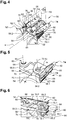
- the connecting device 50 comprises at least one system 80 for limiting the travel of the spreader bar 58.
- the connecting device 50 comprises first and second limiting systems 80, 80 'respectively for the first and second ends 58.1, 58.2 of the lifter 58.
- the limiting system 80 comprises an extension 82 integral with the end 58.1, 58.2 of the lifter 58, projecting from the secondary yoke 68 housing the end 58.1, 58.2 of the lifter 58, as well as the upper and lower stops 84, 86, integral with the first or second fitting 74, 74 ', between which the extension 82 is positioned.
- the sum of the distances between the upper stop 84 and the extension 82 as well as between the lower stop 86 and the extension 82 is substantially less than or equal to 0.3 mm.
- Each extension 82 comprises an upper face 82.1 oriented towards the upper stop 84 and a lower face 82.2 oriented towards the lower stop 86.
- the upper and lower faces 82.1, 82.2 are parallel and plane.
- Each upper or lower stop 84, 86 comprises a contact face 84.1, 86.1, substantially planar, against which the extension 82 can bear.
- the contact faces 84.1, 86.1 of the upper and lower stops 84, 86 are mutually parallel.
- At least one of the contact faces 84.1, 86.1 comprises a damping coating 88 configured to damp the contact between one of the upper and lower stops 84, 86 and the extension 82.
- the coating damper 88 comprises cylindrical elements in the form of metal sponges.
- each system for limiting the movement 80 the upper and lower stops 84, 86 are separate from the fitting 74, 74 '.
- Each device 80 for limiting the movement comprises a plate 90, pressed against and fixed against a side face 92 of the fitting 74, 74 ', to which the upper and lower stops 84, 86 are connected.
- the upper and lower stops 84, 86 as well. that the plate 90 form a single piece in Y, the upper and lower stops 84, 86 forming the branches of the Y-shape and the plate 90 forming the foot of the Y-shape.
- the upper stop 84 comprises a first wing 84.2 configured to be pressed against the outer face 76E of the upper branch 76 of the fitting 74, 74 'and the lower stop 86 comprises a second wing 86.2 configured to be pressed against the outer face 78E of the lower branch 78 of the fitting 74, 74 ', as illustrated in the figure 6 .
- the upper and lower stops 84, 86 are separate from the fitting 74, 74 'and independent of one another.
- the upper stop 84 is connected to the upper branch 76 of the fitting 74, 74' and the lower stop 86 is connected to the lower branch 78 of the fitting 74, 74 '.
- each upper or lower stop 84, 86 comprises a parallelepipedal body 94 which has a first face corresponding to the contact face 84.1, 86.1 and a second face 84.3, 86.3, parallel to the first face, configured to be pressed against the inner face 76l or 78l of the upper or lower branch 76, 78.
- Each upper or lower stop 84, 86 comprises a wing 96, made in one piece with the body 94, configured to be pressed against the side face 76L, 78L of the upper or lower branch 76, 78.
- the wing 96 comprises a lug 98 configured to cooperate with a notch 100 provided at the level of the lateral face 76L, 78L of the upper or lower branch 76, 78 so as to immobilize the lug 98 in translation relative to the notch 100.
- each upper or lower stop 84, 86 is connected to the upper or lower branch 76, 78 by two connecting elements 102, such as for example a screw and a barrel nut.
- the upper stop 84 is integrated into the upper branch 76 of the fitting 74, 74 'and the lower stop 86 is integrated into the lower branch 78 of the fitting 74, 74'.
- the upper branch 76 comprises an upper wing 104 projecting from the inner face 76l of the branch.
- upper 76, the upper wing 104 comprising an interior face 104.1 which corresponds to the contact face 84.1 of the upper stop 84.
- the lower branch 78 comprises a lower wing 106 projecting from the interior face 78l of the lower branch 78 , the lower wing 106 comprising an inner face 106.1 which corresponds to the contact face 86.1 of the lower stop 86.
- the limitation systems 80 make it possible to increase the out-of-plane rigidity of the lifter 58 and to obtain a decoupling of certain natural modes from the primary thrust paths and from the engine frequencies.
Landscapes
- Engineering & Computer Science (AREA)
- Aviation & Aerospace Engineering (AREA)
- Connection Of Plates (AREA)
- Mutual Connection Of Rods And Tubes (AREA)
- Transmission Devices (AREA)
Claims (12)
- Verbindungsvorrichtung, die dazu eingerichtet ist, ein Triebwerk eines Luftfahrzeugs und eine Primärstruktur eines Triebwerkträgers eines Luftfahrzeugs zu verbinden, mit:- einem Träger (54), der dazu eingerichtet ist, mit der Primärstruktur verbunden zu werden,- einer Traverse (58), die sich zwischen einem ersten und einem zweiten Ende (58.1, 58.2) erstreckt, die ein Mittelteil (58.3) aufweist, das mit dem Träger (54) durch eine Hauptverbindung (60) verbunden ist, und die eine Hauptdrehachse (66) aufweist,- einer ersten Schubstange (52), die ein erstes Ende (52.1) aufweist, das mit dem ersten Ende (58.1) der Traverse (58) durch eine erste sekundäre Verbindung (62) verbunden ist, und ein zweites Ende aufweist, das dazu eingerichtet ist, mit dem Triebwerk verbunden zu sein,- eine zweite Schubstange (52'), die ein erstes Ende (52.1') aufweist, das mit dem zweiten Ende (58.2) der Traverse (58) durch eine zweite sekundäre Verbindung (62') verbunden ist, und ein zweites Ende aufweist, das dazu eingerichtet ist, mit dem Triebwerk verbunden zu sein,- erste und zweite Anschlussstücke (74, 74'), die mit dem Träger (54) fest verbunden sind und die obere und untere Schenkel (76, 78) aufweisen, zwischen denen die Traverse (58) angeordnet ist,- dadurch gekennzeichnet, dass die Verbindungsvorrichtung (50) einen Ausschlag der Traverse (58) zulässt, die um eine zur Hauptdrehachse (66) senkrechte und in einer Symmetrieebene (Ps) gelegene Drehachse (R) schwenken kann, die durch die Hauptdrehachse (66) hindurchgeht; und dassdie Verbindungsvorrichtung (50) zusätzlich wenigstens ein Begrenzungssystem (80) für den Ausschlag der Traverse (58) aufweist, das eine mit der Traverse (58) fest verbundene Verlängerung (82) sowie obere und untere Anschläge (84, 86) aufweist, die mit dem ersten oder zweiten Anschlussstück (74, 74'), zwischen denen die Verlängerung (82) angeordnet ist, fest verbunden sind.
- Verbindungsvorrichtung nach Anspruch 1, dadurch gekennzeichnet, dass das Begrenzungssystem (80) für den Ausschlag der Traverse (58) so ausgebildet ist, dass die Summe der Abstände zwischen dem oberen Anschlag (84) und der Verlängerung (82) sowie zwischen dem unteren Anschlag (86) und der Verlängerung (82) kleiner gleich 0,3 mm ist.
- Verbindungsvorrichtung nach Anspruch 1 oder 2, dadurch gekennzeichnet, dass die Verbindungsvorrichtung (50) ein erstes und zweites Begrenzungssysteme (80, 80') für den Ausschlag der Traverse (58) aufweist, die jeweils an dem ersten und zweiten Anschlussstück befestigt sind (74, 74').
- Verbindungsvorrichtung nach einem der vorhergehenden Ansprüche, dadurch gekennzeichnet, dass der obere oder untere Anschlag (84, 86) jeweils eine Kontaktfläche (84.1, 86.1) aufweist, an der die Verlängerung (82) anliegen kann, wobei wenigstens einer der Kontaktflächen (84.1, 86.1) eine dämpfende Beschichtung (88) aufweist.
- Verbindungsvorrichtung nach einem der vorhergehenden Ansprüche, dadurch gekennzeichnet, dass bei jedem Begrenzungssystem (80) für die Ausschläge die oberen und unteren Anschläge (84, 86) vom Anschlussstück (74, 74') getrennt sind und dass jede Begrenzungsvorrichtung (80) für den Ausschlag eine am Anschlussstück (74, 74') befestigte Platte (90) aufweist, mit der die oberen und unteren Anschläge (84, 86) verbunden sind.
- Verbindungsvorrichtung nach dem vorhergehenden Anspruch, dadurch gekennzeichnet, dass der obere Anschlag (84) einen ersten Flügel (84.2) aufweist, der dazu eingerichtet ist, gegen eine Außenfläche (76E) des oberen Schenkels (76) des Anschlussstücks (74, 74') angesetzt zu sein, und dass der untere Anschlag (86) einen zweiten Flügel (86.2) aufweist, der dazu eingerichtet ist, gegen eine Außenfläche (78E) des unteren Schenkels (78) des Anschlussstücks (74, 74') angesetzt zu sein.
- Verbindungsvorrichtung nach einem der Ansprüche 1 bis 4, dadurch gekennzeichnet, dass bei jedem Begrenzungssystem (80) für den Ausschlag der obere und untere Anschlag (84, 86) vom Anschlussstück (74, 74') getrennt und voneinander unabhängig sind, wobei der obere Anschlag (84) mit dem oberen Schenkel (76) des Anschlussstücks (74, 74') verbunden ist und der untere Anschlag (86) mit dem unteren Schenkel (78) des Anschlussstücks (74, 74') verbunden ist.
- Verbindungsvorrichtung nach dem vorhergehenden Anspruch, dadurch gekennzeichnet, dass jeder obere oder untere Anschlag (84, 86) versehen ist mit:- einem Körper (94), der eine erste Fläche aufweist, die eine Kontaktfläche (84.1, 86.1) bildet, an der die Verlängerung (82) anliegen kann, und eine zweite Fläche (84.3, 86.3) aufweist, die parallel zur ersten Fläche ist und die gegen eine Innenfläche (76I, 78I) des oberen oder unteren Schenkels (76, 78) des Anschlussstücks (74, 74') angesetzt ist, und- einem mit dem Körper (94) einstückig ausgebildeten Flügel (96), der gegen eine Seitenfläche (76L, 78L) des oberen oder unteren Schenkels (76, 78) des Anschlussstücks (74, 74') angesetzt ist.
- Verbindungsvorrichtung nach dem vorhergehenden Anspruch, dadurch gekennzeichnet, dass der Flügel (96) einen Vorsprung (98) aufweist, die mit einem Einzug (100) zusammenwirkt, der an der Seitenfläche (76L, 78L) des oberen oder unteren Schenkels (76, 78) des Anschlussstückes (74, 74') vorgesehen ist.
- Verbindungsvorrichtung nach einem der Ansprüche 1 bis 4, dadurch gekennzeichnet, dass bei jedem Begrenzungssystem (80) für den Ausschlag der obere Anschlag (84) in den oberen Schenkel (76) des Anschlussstücks (74, 74') integriert ist und der untere Anschlag (86) in den unteren Schenkel (78) des Anschlussstücks (74, 74') integriert ist.
- Verbindungsvorrichtung nach dem vorhergehenden Anspruch, dadurch gekennzeichnet, dass der obere Schenkel (76) einen von einer Innenseite (76I) des oberen Schenkels (76) abstehenden oberen Flügel (104) umfasst, der eine Innenseite (104.1) aufweist, an dem die Verlängerung (82) anliegen kann, und dass der untere Schenkel (78) einen von einer Innenseite (78I) des unteren Schenkels (78) abstehenden unteren Flügel (106) aufweist, der eine Innenseite (106.1) aufweist, an der die Verlängerung (82) anliegen kann.
- Luftfahrzeug mit einer Verbindungsvorrichtung nach einem der vorhergehenden Ansprüche.
Applications Claiming Priority (1)
| Application Number | Priority Date | Filing Date | Title |
|---|---|---|---|
| FR1902219A FR3093504A1 (fr) | 2019-03-05 | 2019-03-05 | Dispositif de liaison reliant un moteur d’aéronef et une structure primaire d’un mât d’aéronef comprenant un palonnier et un système de limitation du débattement hors plan du palonnier, aéronef comprenant un tel dispositif de liaison |
Publications (2)
| Publication Number | Publication Date |
|---|---|
| EP3705404A1 EP3705404A1 (de) | 2020-09-09 |
| EP3705404B1 true EP3705404B1 (de) | 2021-12-22 |
Family
ID=67810690
Family Applications (1)
| Application Number | Title | Priority Date | Filing Date |
|---|---|---|---|
| EP20157992.7A Active EP3705404B1 (de) | 2019-03-05 | 2020-02-18 | Verbindungsvorrichtung zwischen einem luftfahrzeugmotor und einer primärstruktur eines luftfahrzeugmasts, die ein seitensteuerpedal und ein system für die begrenzung des ruderausschlags ausserhalb der ebene umfasst, und eine solche verbindungsvorrichtung umfassendes luftfahrzeug |
Country Status (3)
| Country | Link |
|---|---|
| US (1) | US11325715B2 (de) |
| EP (1) | EP3705404B1 (de) |
| FR (1) | FR3093504A1 (de) |
Families Citing this family (2)
| Publication number | Priority date | Publication date | Assignee | Title |
|---|---|---|---|---|
| FR3114300A1 (fr) | 2020-09-21 | 2022-03-25 | Airbus Operations (S.A.S.) | Assemblage d’un moteur avec un mat d’aeronef |
| FR3122164B1 (fr) | 2021-04-27 | 2023-06-02 | Airbus Operations Sas | Dispositif de liaison reliant un moteur d’aéronef et une structure primaire d’un mât d’aéronef comprenant un palonnier ainsi qu’un système de limitation du débattement du palonnier intégrant une double butée, aéronef comprenant un tel dispositif de liaison |
Family Cites Families (4)
| Publication number | Priority date | Publication date | Assignee | Title |
|---|---|---|---|---|
| US5320307A (en) * | 1992-03-25 | 1994-06-14 | General Electric Company | Aircraft engine thrust mount |
| FR2806699B1 (fr) * | 2000-03-22 | 2002-05-10 | Aerospatiale Matra Airbus | Dispositif de reprise de poussee apte a relier un turbomoteur et un mat d'aeronef |
| FR2959210B1 (fr) * | 2010-04-21 | 2013-08-23 | Snecma | Palonnier de suspension de turboreacteur d'aeronef et suspension avec accroche-soufflante ainsi equipee |
| FR3041996B1 (fr) * | 2015-10-05 | 2017-10-27 | Snecma | Systeme de suspension de deux modules d'un ensemble propulsif |
-
2019
- 2019-03-05 FR FR1902219A patent/FR3093504A1/fr not_active Ceased
-
2020
- 2020-02-18 EP EP20157992.7A patent/EP3705404B1/de active Active
- 2020-03-03 US US16/807,351 patent/US11325715B2/en active Active
Also Published As
| Publication number | Publication date |
|---|---|
| EP3705404A1 (de) | 2020-09-09 |
| US20200346771A1 (en) | 2020-11-05 |
| FR3093504A1 (fr) | 2020-09-11 |
| US11325715B2 (en) | 2022-05-10 |
Similar Documents
| Publication | Publication Date | Title |
|---|---|---|
| EP3705404B1 (de) | Verbindungsvorrichtung zwischen einem luftfahrzeugmotor und einer primärstruktur eines luftfahrzeugmasts, die ein seitensteuerpedal und ein system für die begrenzung des ruderausschlags ausserhalb der ebene umfasst, und eine solche verbindungsvorrichtung umfassendes luftfahrzeug | |
| FR2999149A1 (fr) | Fuselage pour aeronef comportant un dispositif de liaison configure pour etre relie a un caisson de voilure de l'aeronef et pour transmettre a ce caisson des efforts subis par le fuselage | |
| CA2849239A1 (fr) | Ensemble propulsif d'aeronef | |
| EP3718899B1 (de) | Hintere motorhalterung mit reduzierter breite für ein flugzeug und flugzeug mit mindestens einer solchen hinteren motorhalterung | |
| EP3505439A1 (de) | Einheit für ein luftfahrzeug, die eine primärstruktur eines aufhängungsmasts umfasst, die an einem flügelkasten durch befestigungselemente befestigt ist und im vorderkantenbereich ein reduziertes volumen aufweist | |
| EP3486174B1 (de) | Hintere motorbefestigung für einen luftfahrzeugmotor | |
| FR3098793A1 (fr) | Ensemble propulseur comprenant une attache moteur avant améliorée et aéronef comprenant au moins un tel ensemble propulseur | |
| EP3939891B1 (de) | Anordnung für ein luftfahrzeug aus einem flügel und einem triebwerksträger zur ankopplung eines turbotriebwerks an diesen flügel | |
| EP4368512A1 (de) | Anordnung für ein flugzeug mit einem flügel und einem reaktormast zur kopplung eines antriebssystems an den flügel | |
| EP4124575B1 (de) | Antriebsbaugruppe für flugzeuge mit einem turbojet, einem mast und mitteln zum befestigen des turbojet an dem mast | |
| FR3122164A1 (fr) | Dispositif de liaison reliant un moteur d’aéronef et une structure primaire d’un mât d’aéronef comprenant un palonnier ainsi qu’un système de limitation du débattement du palonnier intégrant une double butée, aéronef comprenant un tel dispositif de liaison | |
| EP3715258A1 (de) | Hintere motorbefestigung eines luftfahrzeugs, die schwingarme aus zwei teilen umfasst, und luftfahrzeug, das mindestens eine solche hintere motorbefestigung umfasst | |
| FR3135450A1 (fr) | Assemblage d’un mât réacteur avec une aile d’un aeronef. | |
| EP4438486B1 (de) | Antriebseinheit für ein flugzeug mit einem turbintriebwerk, einem mast und mitteln zum einrasten des turbintriebwerks an den mast | |
| EP4491518B1 (de) | Flugzeugtriebwerkanordnung mit einer hauptstange zur motorbefestigung, sowie zwei parallel an einer querverstärkung vor einer primärstruktur eines masts | |
| EP3728039B1 (de) | Aufhängevorrichtung | |
| FR3083776A1 (fr) | Mat d'accrochage pour un turboreacteur d'un aeronef comportant une structure particuliere | |
| FR3058388A1 (fr) | Attache arriere d'un moteur d'aeronef | |
| EP4253247B1 (de) | Kompakte elektrische antriebsanordnung mit isostatischer motorbefestigung, flugzeug mit mindestens einer solchen elektrischen antriebsanordnung | |
| EP4342799B1 (de) | Motorisierungseinheit für ein flugzeug mit einer vorrichtung zur aufnahme von schubkräften | |
| EP4488178B1 (de) | Montage eines befestigungsmastes mit einem flugzeugmotor | |
| FR3118944A1 (fr) | Structure primaire d’un mât pour la fixation d’un moteur d’aéronef. | |
| EP4321438B1 (de) | Flugzeug mit einer struktur, einem tank und mitteln zur befestigung des tanks an der struktur | |
| EP4592188A1 (de) | Antriebseinheit für ein flugzeug mit einem triebwerk, einem mast und mitteln zur befestigung des triebwerks an dem mast | |
| EP4467461B1 (de) | Anordnung für ein flugzeug mit einem flügel und einem triebwerkmast zur kopplung eines antriebssystems an den flügel |
Legal Events
| Date | Code | Title | Description |
|---|---|---|---|
| PUAI | Public reference made under article 153(3) epc to a published international application that has entered the european phase |
Free format text: ORIGINAL CODE: 0009012 |
|
| STAA | Information on the status of an ep patent application or granted ep patent |
Free format text: STATUS: THE APPLICATION HAS BEEN PUBLISHED |
|
| AK | Designated contracting states |
Kind code of ref document: A1 Designated state(s): AL AT BE BG CH CY CZ DE DK EE ES FI FR GB GR HR HU IE IS IT LI LT LU LV MC MK MT NL NO PL PT RO RS SE SI SK SM TR |
|
| AX | Request for extension of the european patent |
Extension state: BA ME |
|
| STAA | Information on the status of an ep patent application or granted ep patent |
Free format text: STATUS: REQUEST FOR EXAMINATION WAS MADE |
|
| 17P | Request for examination filed |
Effective date: 20210225 |
|
| RBV | Designated contracting states (corrected) |
Designated state(s): AL AT BE BG CH CY CZ DE DK EE ES FI FR GB GR HR HU IE IS IT LI LT LU LV MC MK MT NL NO PL PT RO RS SE SI SK SM TR |
|
| GRAP | Despatch of communication of intention to grant a patent |
Free format text: ORIGINAL CODE: EPIDOSNIGR1 |
|
| STAA | Information on the status of an ep patent application or granted ep patent |
Free format text: STATUS: GRANT OF PATENT IS INTENDED |
|
| INTG | Intention to grant announced |
Effective date: 20210720 |
|
| GRAS | Grant fee paid |
Free format text: ORIGINAL CODE: EPIDOSNIGR3 |
|
| GRAA | (expected) grant |
Free format text: ORIGINAL CODE: 0009210 |
|
| STAA | Information on the status of an ep patent application or granted ep patent |
Free format text: STATUS: THE PATENT HAS BEEN GRANTED |
|
| AK | Designated contracting states |
Kind code of ref document: B1 Designated state(s): AL AT BE BG CH CY CZ DE DK EE ES FI FR GB GR HR HU IE IS IT LI LT LU LV MC MK MT NL NO PL PT RO RS SE SI SK SM TR |
|
| REG | Reference to a national code |
Ref country code: GB Ref legal event code: FG4D Free format text: NOT ENGLISH |
|
| REG | Reference to a national code |
Ref country code: CH Ref legal event code: EP |
|
| REG | Reference to a national code |
Ref country code: DE Ref legal event code: R096 Ref document number: 602020001326 Country of ref document: DE |
|
| REG | Reference to a national code |
Ref country code: AT Ref legal event code: REF Ref document number: 1456906 Country of ref document: AT Kind code of ref document: T Effective date: 20220115 |
|
| REG | Reference to a national code |
Ref country code: IE Ref legal event code: FG4D Free format text: LANGUAGE OF EP DOCUMENT: FRENCH |
|
| REG | Reference to a national code |
Ref country code: LT Ref legal event code: MG9D |
|
| PG25 | Lapsed in a contracting state [announced via postgrant information from national office to epo] |
Ref country code: RS Free format text: LAPSE BECAUSE OF FAILURE TO SUBMIT A TRANSLATION OF THE DESCRIPTION OR TO PAY THE FEE WITHIN THE PRESCRIBED TIME-LIMIT Effective date: 20211222 Ref country code: LT Free format text: LAPSE BECAUSE OF FAILURE TO SUBMIT A TRANSLATION OF THE DESCRIPTION OR TO PAY THE FEE WITHIN THE PRESCRIBED TIME-LIMIT Effective date: 20211222 Ref country code: FI Free format text: LAPSE BECAUSE OF FAILURE TO SUBMIT A TRANSLATION OF THE DESCRIPTION OR TO PAY THE FEE WITHIN THE PRESCRIBED TIME-LIMIT Effective date: 20211222 Ref country code: BG Free format text: LAPSE BECAUSE OF FAILURE TO SUBMIT A TRANSLATION OF THE DESCRIPTION OR TO PAY THE FEE WITHIN THE PRESCRIBED TIME-LIMIT Effective date: 20220322 |
|
| REG | Reference to a national code |
Ref country code: NL Ref legal event code: MP Effective date: 20211222 |
|
| REG | Reference to a national code |
Ref country code: AT Ref legal event code: MK05 Ref document number: 1456906 Country of ref document: AT Kind code of ref document: T Effective date: 20211222 |
|
| PG25 | Lapsed in a contracting state [announced via postgrant information from national office to epo] |
Ref country code: SE Free format text: LAPSE BECAUSE OF FAILURE TO SUBMIT A TRANSLATION OF THE DESCRIPTION OR TO PAY THE FEE WITHIN THE PRESCRIBED TIME-LIMIT Effective date: 20211222 Ref country code: NO Free format text: LAPSE BECAUSE OF FAILURE TO SUBMIT A TRANSLATION OF THE DESCRIPTION OR TO PAY THE FEE WITHIN THE PRESCRIBED TIME-LIMIT Effective date: 20220322 Ref country code: LV Free format text: LAPSE BECAUSE OF FAILURE TO SUBMIT A TRANSLATION OF THE DESCRIPTION OR TO PAY THE FEE WITHIN THE PRESCRIBED TIME-LIMIT Effective date: 20211222 Ref country code: HR Free format text: LAPSE BECAUSE OF FAILURE TO SUBMIT A TRANSLATION OF THE DESCRIPTION OR TO PAY THE FEE WITHIN THE PRESCRIBED TIME-LIMIT Effective date: 20211222 Ref country code: GR Free format text: LAPSE BECAUSE OF FAILURE TO SUBMIT A TRANSLATION OF THE DESCRIPTION OR TO PAY THE FEE WITHIN THE PRESCRIBED TIME-LIMIT Effective date: 20220323 |
|
| PG25 | Lapsed in a contracting state [announced via postgrant information from national office to epo] |
Ref country code: NL Free format text: LAPSE BECAUSE OF FAILURE TO SUBMIT A TRANSLATION OF THE DESCRIPTION OR TO PAY THE FEE WITHIN THE PRESCRIBED TIME-LIMIT Effective date: 20211222 |
|
| PG25 | Lapsed in a contracting state [announced via postgrant information from national office to epo] |
Ref country code: SM Free format text: LAPSE BECAUSE OF FAILURE TO SUBMIT A TRANSLATION OF THE DESCRIPTION OR TO PAY THE FEE WITHIN THE PRESCRIBED TIME-LIMIT Effective date: 20211222 Ref country code: SK Free format text: LAPSE BECAUSE OF FAILURE TO SUBMIT A TRANSLATION OF THE DESCRIPTION OR TO PAY THE FEE WITHIN THE PRESCRIBED TIME-LIMIT Effective date: 20211222 Ref country code: RO Free format text: LAPSE BECAUSE OF FAILURE TO SUBMIT A TRANSLATION OF THE DESCRIPTION OR TO PAY THE FEE WITHIN THE PRESCRIBED TIME-LIMIT Effective date: 20211222 Ref country code: PT Free format text: LAPSE BECAUSE OF FAILURE TO SUBMIT A TRANSLATION OF THE DESCRIPTION OR TO PAY THE FEE WITHIN THE PRESCRIBED TIME-LIMIT Effective date: 20220422 Ref country code: ES Free format text: LAPSE BECAUSE OF FAILURE TO SUBMIT A TRANSLATION OF THE DESCRIPTION OR TO PAY THE FEE WITHIN THE PRESCRIBED TIME-LIMIT Effective date: 20211222 Ref country code: EE Free format text: LAPSE BECAUSE OF FAILURE TO SUBMIT A TRANSLATION OF THE DESCRIPTION OR TO PAY THE FEE WITHIN THE PRESCRIBED TIME-LIMIT Effective date: 20211222 Ref country code: CZ Free format text: LAPSE BECAUSE OF FAILURE TO SUBMIT A TRANSLATION OF THE DESCRIPTION OR TO PAY THE FEE WITHIN THE PRESCRIBED TIME-LIMIT Effective date: 20211222 |
|
| PG25 | Lapsed in a contracting state [announced via postgrant information from national office to epo] |
Ref country code: PL Free format text: LAPSE BECAUSE OF FAILURE TO SUBMIT A TRANSLATION OF THE DESCRIPTION OR TO PAY THE FEE WITHIN THE PRESCRIBED TIME-LIMIT Effective date: 20211222 Ref country code: AT Free format text: LAPSE BECAUSE OF FAILURE TO SUBMIT A TRANSLATION OF THE DESCRIPTION OR TO PAY THE FEE WITHIN THE PRESCRIBED TIME-LIMIT Effective date: 20211222 |
|
| REG | Reference to a national code |
Ref country code: DE Ref legal event code: R119 Ref document number: 602020001326 Country of ref document: DE |
|
| PG25 | Lapsed in a contracting state [announced via postgrant information from national office to epo] |
Ref country code: MC Free format text: LAPSE BECAUSE OF FAILURE TO SUBMIT A TRANSLATION OF THE DESCRIPTION OR TO PAY THE FEE WITHIN THE PRESCRIBED TIME-LIMIT Effective date: 20211222 Ref country code: IS Free format text: LAPSE BECAUSE OF FAILURE TO SUBMIT A TRANSLATION OF THE DESCRIPTION OR TO PAY THE FEE WITHIN THE PRESCRIBED TIME-LIMIT Effective date: 20220422 |
|
| REG | Reference to a national code |
Ref country code: BE Ref legal event code: MM Effective date: 20220228 |
|
| PLBE | No opposition filed within time limit |
Free format text: ORIGINAL CODE: 0009261 |
|
| STAA | Information on the status of an ep patent application or granted ep patent |
Free format text: STATUS: NO OPPOSITION FILED WITHIN TIME LIMIT |
|
| PG25 | Lapsed in a contracting state [announced via postgrant information from national office to epo] |
Ref country code: LU Free format text: LAPSE BECAUSE OF NON-PAYMENT OF DUE FEES Effective date: 20220218 Ref country code: DK Free format text: LAPSE BECAUSE OF FAILURE TO SUBMIT A TRANSLATION OF THE DESCRIPTION OR TO PAY THE FEE WITHIN THE PRESCRIBED TIME-LIMIT Effective date: 20211222 Ref country code: AL Free format text: LAPSE BECAUSE OF FAILURE TO SUBMIT A TRANSLATION OF THE DESCRIPTION OR TO PAY THE FEE WITHIN THE PRESCRIBED TIME-LIMIT Effective date: 20211222 |
|
| 26N | No opposition filed |
Effective date: 20220923 |
|
| PG25 | Lapsed in a contracting state [announced via postgrant information from national office to epo] |
Ref country code: IE Free format text: LAPSE BECAUSE OF NON-PAYMENT OF DUE FEES Effective date: 20220218 Ref country code: DE Free format text: LAPSE BECAUSE OF NON-PAYMENT OF DUE FEES Effective date: 20220901 |
|
| PG25 | Lapsed in a contracting state [announced via postgrant information from national office to epo] |
Ref country code: SI Free format text: LAPSE BECAUSE OF FAILURE TO SUBMIT A TRANSLATION OF THE DESCRIPTION OR TO PAY THE FEE WITHIN THE PRESCRIBED TIME-LIMIT Effective date: 20211222 Ref country code: BE Free format text: LAPSE BECAUSE OF NON-PAYMENT OF DUE FEES Effective date: 20220228 |
|
| PG25 | Lapsed in a contracting state [announced via postgrant information from national office to epo] |
Ref country code: IT Free format text: LAPSE BECAUSE OF FAILURE TO SUBMIT A TRANSLATION OF THE DESCRIPTION OR TO PAY THE FEE WITHIN THE PRESCRIBED TIME-LIMIT Effective date: 20211222 |
|
| REG | Reference to a national code |
Ref country code: CH Ref legal event code: PL |
|
| PG25 | Lapsed in a contracting state [announced via postgrant information from national office to epo] |
Ref country code: LI Free format text: LAPSE BECAUSE OF NON-PAYMENT OF DUE FEES Effective date: 20230228 Ref country code: CH Free format text: LAPSE BECAUSE OF NON-PAYMENT OF DUE FEES Effective date: 20230228 |
|
| PG25 | Lapsed in a contracting state [announced via postgrant information from national office to epo] |
Ref country code: MK Free format text: LAPSE BECAUSE OF FAILURE TO SUBMIT A TRANSLATION OF THE DESCRIPTION OR TO PAY THE FEE WITHIN THE PRESCRIBED TIME-LIMIT Effective date: 20211222 Ref country code: CY Free format text: LAPSE BECAUSE OF FAILURE TO SUBMIT A TRANSLATION OF THE DESCRIPTION OR TO PAY THE FEE WITHIN THE PRESCRIBED TIME-LIMIT Effective date: 20211222 |
|
| PG25 | Lapsed in a contracting state [announced via postgrant information from national office to epo] |
Ref country code: HU Free format text: LAPSE BECAUSE OF FAILURE TO SUBMIT A TRANSLATION OF THE DESCRIPTION OR TO PAY THE FEE WITHIN THE PRESCRIBED TIME-LIMIT; INVALID AB INITIO Effective date: 20200218 |
|
| PG25 | Lapsed in a contracting state [announced via postgrant information from national office to epo] |
Ref country code: TR Free format text: LAPSE BECAUSE OF FAILURE TO SUBMIT A TRANSLATION OF THE DESCRIPTION OR TO PAY THE FEE WITHIN THE PRESCRIBED TIME-LIMIT Effective date: 20211222 |
|
| PG25 | Lapsed in a contracting state [announced via postgrant information from national office to epo] |
Ref country code: MT Free format text: LAPSE BECAUSE OF FAILURE TO SUBMIT A TRANSLATION OF THE DESCRIPTION OR TO PAY THE FEE WITHIN THE PRESCRIBED TIME-LIMIT Effective date: 20211222 |
|
| PGFP | Annual fee paid to national office [announced via postgrant information from national office to epo] |
Ref country code: GB Payment date: 20260220 Year of fee payment: 7 |
|
| PGFP | Annual fee paid to national office [announced via postgrant information from national office to epo] |
Ref country code: FR Payment date: 20260218 Year of fee payment: 7 |