EP4342799B1 - Motorisierungseinheit für ein flugzeug mit einer vorrichtung zur aufnahme von schubkräften - Google Patents
Motorisierungseinheit für ein flugzeug mit einer vorrichtung zur aufnahme von schubkräften Download PDFInfo
- Publication number
- EP4342799B1 EP4342799B1 EP23198306.5A EP23198306A EP4342799B1 EP 4342799 B1 EP4342799 B1 EP 4342799B1 EP 23198306 A EP23198306 A EP 23198306A EP 4342799 B1 EP4342799 B1 EP 4342799B1
- Authority
- EP
- European Patent Office
- Prior art keywords
- bore
- axis
- female
- clevis
- coaxial
- Prior art date
- Legal status (The legal status is an assumption and is not a legal conclusion. Google has not performed a legal analysis and makes no representation as to the accuracy of the status listed.)
- Active
Links
Images


Classifications
-
- F—MECHANICAL ENGINEERING; LIGHTING; HEATING; WEAPONS; BLASTING
- F01—MACHINES OR ENGINES IN GENERAL; ENGINE PLANTS IN GENERAL; STEAM ENGINES
- F01D—NON-POSITIVE DISPLACEMENT MACHINES OR ENGINES, e.g. STEAM TURBINES
- F01D25/00—Component parts, details, or accessories, not provided for in, or of interest apart from, other groups
- F01D25/24—Casings; Casing parts, e.g. diaphragms, casing fastenings
- F01D25/243—Flange connections; Bolting arrangements
-
- B—PERFORMING OPERATIONS; TRANSPORTING
- B64—AIRCRAFT; AVIATION; COSMONAUTICS
- B64D—EQUIPMENT FOR FITTING IN OR TO AIRCRAFT; FLIGHT SUITS; PARACHUTES; ARRANGEMENT OR MOUNTING OF POWER PLANTS OR PROPULSION TRANSMISSIONS IN AIRCRAFT
- B64D27/00—Arrangement or mounting of power plants in aircraft; Aircraft characterised by the type or position of power plants
- B64D27/40—Arrangements for mounting power plants in aircraft
- B64D27/404—Suspension arrangements specially adapted for supporting vertical loads
-
- B—PERFORMING OPERATIONS; TRANSPORTING
- B64—AIRCRAFT; AVIATION; COSMONAUTICS
- B64D—EQUIPMENT FOR FITTING IN OR TO AIRCRAFT; FLIGHT SUITS; PARACHUTES; ARRANGEMENT OR MOUNTING OF POWER PLANTS OR PROPULSION TRANSMISSIONS IN AIRCRAFT
- B64D27/00—Arrangement or mounting of power plants in aircraft; Aircraft characterised by the type or position of power plants
- B64D27/40—Arrangements for mounting power plants in aircraft
- B64D27/406—Suspension arrangements specially adapted for supporting thrust loads, e.g. thrust links
-
- F—MECHANICAL ENGINEERING; LIGHTING; HEATING; WEAPONS; BLASTING
- F05—INDEXING SCHEMES RELATING TO ENGINES OR PUMPS IN VARIOUS SUBCLASSES OF CLASSES F01-F04
- F05D—INDEXING SCHEME FOR ASPECTS RELATING TO NON-POSITIVE-DISPLACEMENT MACHINES OR ENGINES, GAS-TURBINES OR JET-PROPULSION PLANTS
- F05D2240/00—Components
- F05D2240/90—Mounting on supporting structures or systems
- F05D2240/91—Mounting on supporting structures or systems on a stationary structure
-
- F—MECHANICAL ENGINEERING; LIGHTING; HEATING; WEAPONS; BLASTING
- F05—INDEXING SCHEMES RELATING TO ENGINES OR PUMPS IN VARIOUS SUBCLASSES OF CLASSES F01-F04
- F05D—INDEXING SCHEME FOR ASPECTS RELATING TO NON-POSITIVE-DISPLACEMENT MACHINES OR ENGINES, GAS-TURBINES OR JET-PROPULSION PLANTS
- F05D2260/00—Function
- F05D2260/30—Retaining components in desired mutual position
- F05D2260/31—Retaining bolts or nuts
- F05D2260/311—Retaining bolts or nuts of the frangible or shear type
Definitions
- the present invention relates to the general field of attaching a turbomachine under the wing of an aircraft. It relates in particular to an aircraft engine assembly comprising an engine, a mast under which the engine is suspended from the engine attachment means and a device for absorbing thrust forces generated by the engine.
- a motorization assembly which comprises at the front, taking as reference the direction of movement of the aircraft in the air, a front engine attachment, at the rear, a rear engine attachment, and between the two engine attachments, a device for absorbing engine thrust forces.
- the document FR-A-2 915 177 discloses a state-of-the-art motorization assembly.
- the thrust force recovery device 700 described in the aforementioned application comprises two thrust recovery connecting rods 702 and 704 (thrust link in English) arranged on either side of a median vertical plane V of the motorization assembly and which each have a front end attached to the engine and a rear end 702a, 704a articulated to a main fitting 706 by means of a rudder bar 708.
- the rudder bar 708 is pivotally mounted on the main fitting 706 about an axis of rotation R arranged in the median vertical plane V and orthogonal to a mean thrust force transmission plane P comprising the longitudinal axes of the two connecting rods 702 and 704.
- the rudder bar 708 is arranged between two branches 710a-b of the main fitting 706, symmetrical to each other with respect to the vertical plane median V.
- the two connecting rods 702 and 704 are connected to the lifting beam 706 by a single connecting pin L mounted horizontally, which is arranged in the mean plane of transmission of the forces P and orthogonal to the axis of rotation R.
- the connecting pin L is inserted in a bearing 708a of the lifting beam 708 and on each side of the latter, through a ball-jointed ring mounted at the rear end 702a, 704a of each connecting rod 702, 704.
- the connecting pin L mechanically connects on the one hand, without play, the connecting rods 702 and 704 to the lifting beam 706, and on the other hand, with play, the connecting rods 702 and 704 to the main fitting 706 via the two branches 710a-b of the main fitting 706.
- Such a thrust force recovery device 700 is advantageous in that the mounting of the connecting rods 702 and 704 by means of a horizontally mounted connecting shaft L makes it possible to optimize the compactness as well as access for operators via the left and right sides of the motorization assembly.
- such a thrust force recovery device 700 generates out-of-plane forces directed towards the sides and the outside of the device (forces according to the arrows U) at each interface of a connecting rod 702, 704 with the lever 708, which may, in the long term, cause premature wear of the ball-jointed rings.
- An object of the present invention is to propose an aircraft motorization assembly comprising an engine, a mast under which the engine is suspended from engine attachment means and a device for absorbing thrust forces generated by the engine.
- the thrust force recovery device is improved and has secondary force transfer paths.
- the rear engine attachment is hinged to the main fitting.
- the main fitting comprises a central flange crossed by a through bore coaxial with the main axis
- the rudder has a female rear yoke into which the central flange is inserted
- the female rear yoke is made up of two rear branches where each is crossed by a rear bore coaxial with the main axis
- the thrust force recovery device comprises a rear connecting pin fitted into the through bore of the central flange and the rear bores of the female rear yoke, for each connecting rod
- the rudder has a female front yoke into which the rear end of said connecting rod is inserted which is crossed by a through bore coaxial with the corresponding front connecting pin
- each female front yoke is made up of two front branches where each is crossed by a front bore coaxial with the corresponding front connecting pin
- the thrust force recovery device comprises a front connecting pin fitted into the through bore of said connecting rod and in the front bores of the female front yok
- the spreader bar comprises a body and two sides, the body is crossed by the drilling and comprises the rear branches and the front branches, each side is in external support against a rear branch and a front branch of each female front yoke, for each rear bore, the side attached to the rear branch corresponding to said rear bore is crossed by a rear secondary bore coaxial with said rear bore, the rear connecting axis also crosses the rear secondary bores of the sides, for each bore front of a female front yoke, the side attached to the front branch corresponding to said front bore is crossed by a front secondary bore coaxial with said front bore and the front connecting axis also crosses the front secondary bores of the sides.
- the invention also proposes an aircraft, a wing and a motorization assembly according to one of the preceding variants of which the mast is fixed under the wing.
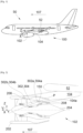
- FIG. 1 shows an aircraft 50 which has a wing 52 under which is mounted a motorization assembly 100 which comprises a turbomachine 102 and a mast 104.
- the longitudinal direction of the turbomachine 102 is called X, this direction X being parallel to a longitudinal axis of the turbomachine 102.
- the transverse direction of the turbomachine 102 which is horizontal when the aircraft is on the ground, is called Y, and the vertical direction or vertical height when the aircraft is on the ground is called Z, these three directions X, Y and Z being orthogonal to each other.
- the motorization assembly 100 comprises a median vertical plane V (XZ) passing through the longitudinal axis of the turbomachine 102 and orthogonal to the longitudinal axis of the turbomachine 102. on the ground and which divides the motor assembly 100 into two left and right parts which are generally symmetrical to each other.
- front and rear are to be considered in relation to a direction of advancement of the aircraft 50 under the effect of the thrust provided by the turbomachine 102 in operation, this direction being represented schematically by the arrow 107.
- FIG. 2 shows the motorization assembly 100 which comprises the turbomachine 102 and the mast 104 by which the turbomachine 102 is fixed under the wing 52.
- the turbomachine 102 comprises a nacelle 202 which surrounds an engine 204 suspended from the mast 104.
- the engine 204 extends from front to rear along the longitudinal axis of the turbomachine 102 and the mast 104 has a lower face 104a which is flat and oriented towards the ground.
- the engine 204 is attached to the mast 104 by a set of engine attachments, attached, on the one hand, to the mast 104 and, on the other hand, to the engine 204.
- These engine attachments comprise at the front, a front engine attachment 206, at the rear, a rear engine attachment 208, and between the front and rear engine attachments, a thrust force recovery device 150.
- the front 206 and rear 208 engine attachments will not be detailed further.
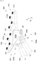
- THE Figs. 3 And 4 show a thrust force recovery device 350 according to a first embodiment of the invention and the Fig. 5 shows a thrust force recovery device 550 according to a second embodiment of the invention.
- the thrust force recovery device 350, 550 comprises a main fitting 310 fixed to the lower face 104a of the mast 104, a rudder bar 320 pivotally mounted on the main fitting 310, and two connecting rods 302 and 304 for recovering the thrust forces of the engine arranged on either side of the median vertical plane V and articulated to the rudder bar 320.
- the main fitting 310 comprises a flat sole 313 pressed against the lower face 104a of the mast 104.
- the fixing of the main fitting 310 to the mast 104 is carried out, for example, by the use of four traction screws 313a through through bores provided for this purpose in the sole 313.
- Each connecting rod 302, 304 has a front end 302b, 304b articulated to the engine 204 of the turbomachine 102 and a rear end 302a, 304a articulated to the rudder 320, and extends longitudinally along a longitudinal axis T1, T2, called the force transmission axis.
- the two force transmission axes T1, T2 are inclined relative to the horizontal and approach each other in a direction going from the front to the rear of the engine assembly 100 (in other words, the axes T1, T2 are convergent in a direction going from the front to the rear of the engine assembly 100).
- the plane containing the two force transmission axes T1 and T2 is called the mean force transmission plane. thrust P.
- Each connecting rod 302, 304 progresses from bottom to top going from the front to the rear of the motor assembly 100.
- the spreader bar 320 is connected to the main fitting 310 by a rear connection point constituting a rotation around an axis of rotation R1, called the main axis, orthogonal to the mean plane of transmission of the thrust forces P and included in the median vertical plane V.
- the rear connection point is made between a central flange 314 of the main fitting 310 and a female rear clevis 322 of the spreader bar 320.
- the central flange 314 is arranged at the front of the main fitting 310 and is integral with the flat sole 313 and extends forward, parallel to the mean plane of transmission of the thrust forces P.
- a through bore 315 is made in the central flange 314, and its bore axis is coaxial with the main axis R1.
- the female rear yoke 322 into which the central flange 314 is inserted is arranged at the rear of the rudder 320.
- the female rear yoke 322 is made up of two rear branches 322a-b parallel to each other and perpendicular to the main axis R1, and each rear branch 322a-b is crossed by a rear bore 323 whose axis is coaxial with the main axis R1.
- the thrust force recovery device 350, 550 comprises a rear connecting pin 324.
- the introduction of the central flange 314 into the female rear yoke 322 and the fitting of the rear connecting pin 324 into the through bore 315 of the central flange 314 and the rear bores 323 of the female rear yoke 322 provide the pivot connection around the main axis R1.
- the connecting pin 324 comprises an axis 324a and a bearing 324b into which said axis 324a is inserted and where said bearing 324b is inserted with a tight fit into the through bore 315 of the central flange 314 and into the rear bores 323 of the female rear yoke 322.
- each connecting rod 302, 304 is articulated to the lever 320 by a front connection point constituting a rotation around a first front connection axis L1 for one connecting rod 302 and around a second front connection axis L2 for the other connecting rod 304.
- the two front connection axes L1, L2 extend parallel to the main axis R1 and symmetrically on either side of the median vertical plane V.
- each front connection point is made between the rear end 302a, 304a of the corresponding connecting rod 302, 304 and a female front clevis 326 of the rudder 320.
- Each female front yoke 326 into which the rear end 302a, 304a of a connecting rod 302, 304 is inserted is arranged at the front of the rocker arm 320.
- each connecting rod 302, 304 is crossed by a through bore 302b, 304b whose axis is coaxial with the corresponding front connecting axis L1, L2.
- Each female front yoke 326 is made up of two front branches 326a-b parallel to each other and perpendicular to the front connecting axis L1, L2, and each front branch 326a-b is crossed by a front bore 327 whose axis is coaxial with the corresponding front connecting axis L1, L2.
- the thrust force recovery device 350, 550 comprises a front connecting axis (not shown).
- each rear end 302a, 304a is mounted in a swivel manner on the front connecting shaft by means of a swivel ring inserted into the through bore 302b, 304b of the corresponding connecting rod 302, 304 and where the connecting shaft is inserted without play into the swivel ring and the front bores 327 of the female front yoke 326.
- a primary force transfer path is thus created between the connecting rods 302 and 304 and the main fitting 310 through the rudder 320 and in particular through the various front 326 and rear 322 female yokes and the corresponding connecting pins.
- the thrust force recovery device 350, 550 comprises a secondary fitting 330 fixed to the lower face 104a of the mast 104 in front of the main fitting 310.
- the secondary fitting 330 comprises a flat sole 331 pressed against the lower face 104a of the mast 104.
- the secondary fitting 330 is fixed to the mast 104, for example, by the use of four traction screws 331a through through bores provided for this purpose in the sole 331.
- the 320 spreader bar is articulated to the 330 secondary fitting.
- the secondary fitting 330 also comprises a secondary female yoke 332 consisting of two secondary branches 332a-b, each having an oblong-shaped hole 333 therethrough.
- the two holes 333 are aligned along an axis R2, called the secondary axis, which is included in the mean plane of transmission of the thrust forces P and perpendicular to the median vertical plane V, that is to say here oriented parallel to the transverse direction Y and horizontally.
- each hole 333 is included in the mean plane of transmission of the thrust forces P and perpendicular to the secondary axis R2.
- the spreader 320 is crossed by a cylindrical bore 334 coaxial with the secondary axis R2 and the spreader 320 is inserted into the secondary female clevis 332 of the secondary fitting 330 so as to align the holes 333 and the bore 334 in order to house a cylindrical secondary connecting pin 336.
- the secondary connecting pin 336 is said to be in standby mode (“waiting fail-safe” in English) which is activated in the event of a failure of the primary path.
- the waiting connecting pin 336 is inserted with a tight fit in the bore 334 and with play in the holes 333.
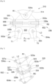
- FIG. 6 shows a section in the normal operating position, i.e. when the primary path is intact.
- the primary path is then faulty and the standby connection axis 336 and the spreader 320 will then tilt to bring said standby connection axis 336 into contact with the edges of the holes 333 and the forces will then pass through a secondary force transfer path to the secondary fitting 330.
- the pending connecting pin 336 here comprises a male part 336a and a female part 336b.
- the male part 336a has a first end 602 whose diameter is equal to the diameter of the bore 334 and a second end 604 of reduced diameter and threaded.
- the female part 336b has an outside diameter equal to the diameter of the bore 334 and an inside diameter equal to the diameter of the second end 604 to fit therein.
- the male part 336a and the female part 336b are secured by a tightening nut 606 which screws onto the second end 604.
- the rear engine attachment 208 is articulated to the main fitting 310, whereas in the embodiment of the invention presented in the Fig. 4 , the rear engine attachment 208 is separate from the main fitting 310.
- the rear engine attachment 208 comprises a three-point rear connecting rod 404, one point 402a of which, included in the median vertical plane V, ensures an articulated mounting to the main fitting 310 and two points 402b-c of which, symmetrical to each other with respect to the median vertical plane V, ensure an articulated mounting to the engine 204 of the turbomachine 102.
- the articulation axis of each point 402a-c is generally parallel to the longitudinal axis of the turbomachine 102.
- the rear connecting rod 402 is mounted articulated in a rear yoke 404 provided under the sole 313 of the main fitting 310.
- the spreader bar 320 is made up of three elements which are shown in detail and in exploded view in Fig. 7 .
- the rudder 320 comprises a body 502 and two flanks 504a-b attached to the body 502 on either side of the body 502 relative to the mean plane of transmission of the thrust forces P, that is to say that here, there is a flank 504a above the body 502 and a flank 504b below the body 502.
- the body 502 is crossed by the drilling 334 and it comprises the rear branches 322a-b to form the female rear yoke 322 and the front branches 326a-b to form the two female front yokes 326.
- Each flank 504a-b bears externally against a rear branch 322a-b of the female rear yoke 322 and a front branch 326a-b of each female front yoke 326.
- the flank 504a-b attached to the rear branch 322a-b corresponding to said rear bore 323 is crossed by a rear secondary bore 323a coaxial with said rear bore 323.
- the rear connecting axis 324 also crosses the rear secondary bores 323a of the flanks 504a-b.
- the flanks 504a-b are sandwiched between the ends of the rear connecting axis 324.
- flank 504a-b attached to the front branch 326a-b corresponding to said front bore 327 is crossed by a front secondary bore 327a coaxial with said front bore 327.
- the corresponding front connecting pin also crosses the front secondary bores 327a of the flanks 504a-b.
- the flanks 504a-b are sandwiched between the ends of each front connecting pin.
- flanks 504a-b take over and constitute a secondary path for transferring forces relative to the body 502 which constitutes the primary path for transferring forces.
Landscapes
- Engineering & Computer Science (AREA)
- Aviation & Aerospace Engineering (AREA)
- Mechanical Engineering (AREA)
- General Engineering & Computer Science (AREA)
- Pivots And Pivotal Connections (AREA)
- Structures Of Non-Positive Displacement Pumps (AREA)
- Automatic Assembly (AREA)
Claims (5)
- Motorisierungseinheit (100) eines Flugzeugs (50), wobei die Motorisierungseinheit (100) eine vertikale Mittelebene (V) aufweist und Folgendes umfasst:- ein Turbotriebwerk (102),- einen Pylon (104),- an der Vorderseite eine vordere Motorbefestigung (206), die das Triebwerk (102) an dem Pylon (104) befestigt,- an der Hinterseite eine hintere Motorbefestigung (208), die das Triebwerk (102) an dem Pylon (104) befestigt, und- eine Schubkräfteaufnahmevorrichtung (150, 350, 550), die Folgendes umfasst:- einen Hauptbeschlag (310), der unter dem Pylon (104) befestigt ist,- eine Traverse (320), die um eine Hauptachse (R1) schwenkbar an dem Hauptbeschlag (310) montiert ist und eine Bohrung (334) aufweist,- zwei Stangen (302, 304) zur Aufnahme der Schubkräfte des Motors, die auf beiden Seiten der vertikalen Mittelebene (V) angeordnet sind, wobei jede Stange (302, 304) ein vorderes Ende (302b, 304b), das an dem Triebwerk (102) angelenkt ist, und ein hinteres Ende (302a, 304a), das an der Traverse (320) angelenkt ist, aufweist, wobei jede Stange (302, 304) eine Längsachse (T1, T2) aufweist, wobei die zwei Längsachsen (T1, T2) eine mittlere Schubkräfteübertragungsebene (P) definieren, wobei die Hauptachse (R1) zu der mittleren Schubkräfteübertragungsebene (P) orthogonal ist und in der vertikalen Mittelebene (V) enthalten ist, wobei das hintere Ende (302a, 304a) jeder Stange (302, 304) um eine vordere Verbindungsachse (L1, L2) parallel zu der Hauptachse (R1) an der Traverse (320) angelenkt ist und wobei die zwei vorderen Verbindungsachsen (L1, L2) mit Bezug auf die vertikale Mittelebene (V) symmetrisch sind,- einen Sekundärbeschlag (330), der unter dem Pylon (104) vor dem Hauptbeschlag (310) befestigt ist und einen sekundären Gabelkopf (332) aufweist, der aus zwei sekundären Armen (332a-b) besteht, von denen jeder von einem Loch (333) mit länglicher Form durchquert wird, wobei die zwei Löcher (333) nach einer sekundären Achse (R2) ausgerichtet sind, die in der mittleren Schubkräfteübertragungsebene (P) enthalten und senkrecht zu der vertikalen Mittelebene (V) ist, und wobei die Hauptachse jedes Lochs (333) in der mittleren Schubkräfteübertragungsebene (P) enthalten und zu der sekundären Achse (R2) senkrecht ist, wobei die Traverse (320) in dem sekundären Gabelkopf (332) des sekundären Beschlags (330) aufgenommen ist, wobei die Bohrung (334) zu der sekundären Achse (R2) koaxial ist, und- eine Ersatzverbindungsachse (336), die mit einem Presssitz in die Bohrung (334) und mit Spiel in die Löcher (333) eingeführt ist.
- Motorisierungseinheit (100) nach Anspruch 1, dadurch gekennzeichnet, dass die hintere Motorbefestigung (208) an dem Hauptbeschlag (310) angelenkt ist.
- Motorisierungseinheit (100) nach einem der Ansprüche 1 oder 2, dadurch gekennzeichnet, dass der Hauptbeschlag (310) einen mittleren Flansch (314) beinhaltet, der von einer Durchgangsbohrung (315), die zu der Hauptachse (R1) koaxial ist, durchquert wird, dass die Traverse (320) einen hinteren Gabelkopf (322) aufweist, in den der mittlere Flansch (314) eingeführt wird, dass der hintere Gabelkopf (322) aus zwei hinteren Armen (322a-b) besteht, von denen jeder von einer hinteren Bohrung (323), die zu der Hauptachse (R1) koaxial ist, durchquert wird, dass die Schubkräfteaufnahmevorrichtung (350, 550) eine hintere Verbindungsachse (324) umfasst, die in die Durchgangsbohrung (315) des mittleren Flansches (314) und die hinteren Bohrungen (323) des hinteren Gabelkopfes (322) eingesteckt wird, dass die Traverse (320) für jede Stange (302, 304) einen vorderen Gabelkopf (326) aufweist, in den das hintere Ende (302a, 304a) der Stange (302, 304), das von einer Durchgangsbohrung (302b, 304b), die zu der entsprechenden vorderen Verbindungsachse (L1, L2) koaxial ist, durchquert wird, eingeführt wird, dass jeder vordere Gabelkopf (326) aus zwei vorderen Armen (326a-b) besteht, von denen jeder von einer vorderen Bohrung (327), die zu der entsprechenden vorderen Verbindungachse (L1, L2) koaxial ist, durchquert wird, und dass die Schubkräfteaufnahmevorrichtung (350, 550) für jede Stange (302, 304) eine vordere Verbindungsachse umfasst, die in die Durchgangsbohrung (302b, 304b) der Stange (302, 304) und in die vorderen Bohrungen (327) des vorderen Gabelkopfes (326) eingesteckt wird.
- Motorisierungseinheit (100) nach Anspruch 3, dadurch gekennzeichnet, dass die Traverse (320) einen Körper (502) und zwei Seitenteile (504a-b) umfasst, dass der Körper (502) von der Bohrung (334) durchquert wird und die hinteren Arme (322a-b) und die vorderen Arme (326a-b) umfasst, dass jedes Seitenteil (504a-b) außen an einem hinteren Arm (322a-b) und einem vorderen Arm (326a-b) jedes vorderen Gabelkopfes (326) anliegt, dass, für jede hintere Bohrung (323), das Seitenteil (504a-b), das an den hinteren Arm (322a-b), der der hinteren Bohrung (323) entspricht, angefügt ist, von einer hinteren sekundären Bohrung (323a) durchquert wird, die zu der hinteren Bohrung (323) koaxial ist, dass die hintere Verbindungsachse (324) ebenfalls die hinteren sekundären Bohrungen (323a) der Seitenteile (504a-b) durchquert, dass, für jede vordere Bohrung (327) eines vorderen Gabelkopfes (326), das Seitenteil (504a-b), das an den vorderen Arm (326a-b), der der vorderen Bohrung (327) entspricht, angefügt ist, von einer vorderen sekundären Bohrung (327a) durchquert wird, die zu der vorderen Bohrung (327) koaxial ist, und dass die vordere Verbindungsachse ebenfalls die vorderen sekundären Bohrungen (327a) der Seitenteile (504a-b) durchquert.
- Flugzeug (50), umfassend eine Tragfläche (52) und eine Motorisierungseinheit (100) nach einem der vorhergehenden Ansprüche, deren Pylon (104) unter der Tragfläche (52) befestigt ist.
Applications Claiming Priority (1)
| Application Number | Priority Date | Filing Date | Title |
|---|---|---|---|
| FR2209679A FR3140068A1 (fr) | 2022-09-23 | 2022-09-23 | Ensemble de motorisation d’aéronef comportant un dispositif de reprise d’efforts de poussée |
Publications (2)
| Publication Number | Publication Date |
|---|---|
| EP4342799A1 EP4342799A1 (de) | 2024-03-27 |
| EP4342799B1 true EP4342799B1 (de) | 2025-05-07 |
Family
ID=84369805
Family Applications (1)
| Application Number | Title | Priority Date | Filing Date |
|---|---|---|---|
| EP23198306.5A Active EP4342799B1 (de) | 2022-09-23 | 2023-09-19 | Motorisierungseinheit für ein flugzeug mit einer vorrichtung zur aufnahme von schubkräften |
Country Status (4)
| Country | Link |
|---|---|
| US (1) | US12337980B2 (de) |
| EP (1) | EP4342799B1 (de) |
| CN (1) | CN117755501A (de) |
| FR (1) | FR3140068A1 (de) |
Family Cites Families (7)
| Publication number | Priority date | Publication date | Assignee | Title |
|---|---|---|---|---|
| US7083143B2 (en) * | 2003-10-17 | 2006-08-01 | The Boeing Company | Apparatuses and methods for attaching engines and other structures to aircraft wings |
| FR2915177B1 (fr) | 2007-04-20 | 2009-07-10 | Airbus France Sa | Dispositif d'accrochage de moteur d'aeronef et aeronef comportant au moins un tel dispositif |
| FR2917713B1 (fr) * | 2007-06-21 | 2009-09-25 | Airbus France Sas | Dispositif d'accrochage de moteur d'aeronef et aeronef comportant au moins un tel dispositif. |
| FR2981047B1 (fr) | 2011-10-06 | 2013-10-25 | Aircelle Sa | Ensemble propulsif d'aeronef |
| US8985509B2 (en) | 2012-08-31 | 2015-03-24 | United Technologies Corporation | Assembly for mounting a turbine engine to a pylon |
| FR3093704B1 (fr) * | 2019-03-11 | 2021-06-11 | Airbus Operations Sas | Attache moteur arrière d’un ensemble propulsif d’aéronef |
| FR3100530B1 (fr) | 2019-09-11 | 2021-07-30 | Airbus Operations Sas | Ensemble de motorisation d’aéronef comprenant un dispositif de reprise d’efforts de poussée |
-
2022
- 2022-09-23 FR FR2209679A patent/FR3140068A1/fr not_active Ceased
-
2023
- 2023-09-19 EP EP23198306.5A patent/EP4342799B1/de active Active
- 2023-09-21 US US18/471,721 patent/US12337980B2/en active Active
- 2023-09-25 CN CN202311244442.6A patent/CN117755501A/zh active Pending
Also Published As
| Publication number | Publication date |
|---|---|
| EP4342799A1 (de) | 2024-03-27 |
| US20240101262A1 (en) | 2024-03-28 |
| FR3140068A1 (fr) | 2024-03-29 |
| CN117755501A (zh) | 2024-03-26 |
| US12337980B2 (en) | 2025-06-24 |
Similar Documents
| Publication | Publication Date | Title |
|---|---|---|
| EP1136355B1 (de) | Schubbefestigung eines Triebwerkes an einem Luftfahrzeug | |
| EP2167384B1 (de) | Gondelstiel zur kupplung eines triebwerks für ein luftfahrzeug mit einem eine rudersteuerstange bildenden hecktriebwerksbefestigungsträger | |
| EP2137072B1 (de) | Vorrichtung zur befestigung eines flugzeugtriebwerks und flugzeug mit mindestens einer derartigen vorrichtung | |
| EP1486418B1 (de) | Triebwerksgondelaufhängung für Luftfahrzeuge | |
| FR2770486A1 (fr) | Dispositif d'accrochage d'un moteur sur un aeronef | |
| CA2613194A1 (fr) | Attache moteur pour aeronef destinee a etre interposee entre un moteur et un mat d'accrochage | |
| EP3483069A1 (de) | Luftfahrezugtriebwerksbefestigungssystem | |
| FR2931800A1 (fr) | Dispositif de reprise des efforts de poussee pour mat d'accrochage de moteur d'aeronef, comprenant des bielles laterales a butees de palonnier integrees | |
| EP1053936A1 (de) | Triebwerksaufhängung für Luftfahrzeuge | |
| EP4484297B1 (de) | Vordermotorbefestigungssystem für einen flugzeugmotor mit kompakter struktur | |
| FR3156756A1 (fr) | Ensemble propulsif pour aéronef comportant un moteur, un mât et des moyens d’accrochage du moteur au mât | |
| FR3093704A1 (fr) | Attache moteur arrière d’un ensemble propulsif d’aéronef | |
| EP4342799B1 (de) | Motorisierungseinheit für ein flugzeug mit einer vorrichtung zur aufnahme von schubkräften | |
| EP4124575A1 (de) | Antriebsbaugruppe für flugzeuge mit einem turbojet, einem mast und mitteln zum befestigen des turbojet an dem mast | |
| EP1571082A1 (de) | Aufhängevorrichtung eines Flugzeugtriebwerks an einem Flügelpylon | |
| FR3096348A1 (fr) | Systeme d’attache moteur avant pour un moteur d’aeronef comportant des systemes de bielles a deux bielles | |
| EP3705404B1 (de) | Verbindungsvorrichtung zwischen einem luftfahrzeugmotor und einer primärstruktur eines luftfahrzeugmasts, die ein seitensteuerpedal und ein system für die begrenzung des ruderausschlags ausserhalb der ebene umfasst, und eine solche verbindungsvorrichtung umfassendes luftfahrzeug | |
| EP4484298B1 (de) | Vordermotorbefestigungssystem für einen flugzeugmotor mit kompakter struktur | |
| EP3728039B1 (de) | Aufhängevorrichtung | |
| EP3971091B1 (de) | Zusammenbau eines motors mit einem luftfahrzeugmast | |
| EP4151838B1 (de) | Flugtriebwerksaufbau mit einer vorrichtung zur aufnahme von schubkräften geeignet zur aufhängung an einem flugzeug | |
| EP4321438B1 (de) | Flugzeug mit einer struktur, einem tank und mitteln zur befestigung des tanks an der struktur | |
| EP4442577B1 (de) | Reaktormast zur befestigung eines flugzeugmotors | |
| EP0767079B1 (de) | Trägerbalken für Anhänger | |
| EP4488178B1 (de) | Montage eines befestigungsmastes mit einem flugzeugmotor |
Legal Events
| Date | Code | Title | Description |
|---|---|---|---|
| PUAI | Public reference made under article 153(3) epc to a published international application that has entered the european phase |
Free format text: ORIGINAL CODE: 0009012 |
|
| STAA | Information on the status of an ep patent application or granted ep patent |
Free format text: STATUS: THE APPLICATION HAS BEEN PUBLISHED |
|
| AK | Designated contracting states |
Kind code of ref document: A1 Designated state(s): AL AT BE BG CH CY CZ DE DK EE ES FI FR GB GR HR HU IE IS IT LI LT LU LV MC ME MK MT NL NO PL PT RO RS SE SI SK SM TR |
|
| STAA | Information on the status of an ep patent application or granted ep patent |
Free format text: STATUS: REQUEST FOR EXAMINATION WAS MADE |
|
| 17P | Request for examination filed |
Effective date: 20240924 |
|
| RBV | Designated contracting states (corrected) |
Designated state(s): AL AT BE BG CH CY CZ DE DK EE ES FI FR GB GR HR HU IE IS IT LI LT LU LV MC ME MK MT NL NO PL PT RO RS SE SI SK SM TR |
|
| REG | Reference to a national code |
Ref country code: DE Ref legal event code: R079 Free format text: PREVIOUS MAIN CLASS: B64D0027260000 Ipc: B64D0027400000 Ref country code: DE Ref legal event code: R079 Ref document number: 602023003340 Country of ref document: DE Free format text: PREVIOUS MAIN CLASS: B64D0027260000 Ipc: B64D0027400000 |
|
| GRAP | Despatch of communication of intention to grant a patent |
Free format text: ORIGINAL CODE: EPIDOSNIGR1 |
|
| STAA | Information on the status of an ep patent application or granted ep patent |
Free format text: STATUS: GRANT OF PATENT IS INTENDED |
|
| RIC1 | Information provided on ipc code assigned before grant |
Ipc: B64D 27/40 20240101AFI20241118BHEP |
|
| INTG | Intention to grant announced |
Effective date: 20241206 |
|
| GRAS | Grant fee paid |
Free format text: ORIGINAL CODE: EPIDOSNIGR3 |
|
| GRAA | (expected) grant |
Free format text: ORIGINAL CODE: 0009210 |
|
| STAA | Information on the status of an ep patent application or granted ep patent |
Free format text: STATUS: THE PATENT HAS BEEN GRANTED |
|
| AK | Designated contracting states |
Kind code of ref document: B1 Designated state(s): AL AT BE BG CH CY CZ DE DK EE ES FI FR GB GR HR HU IE IS IT LI LT LU LV MC ME MK MT NL NO PL PT RO RS SE SI SK SM TR |
|
| REG | Reference to a national code |
Ref country code: GB Ref legal event code: FG4D Free format text: NOT ENGLISH |
|
| REG | Reference to a national code |
Ref country code: CH Ref legal event code: EP |
|
| REG | Reference to a national code |
Ref country code: DE Ref legal event code: R096 Ref document number: 602023003340 Country of ref document: DE |
|
| REG | Reference to a national code |
Ref country code: IE Ref legal event code: FG4D Free format text: LANGUAGE OF EP DOCUMENT: FRENCH |
|
| REG | Reference to a national code |
Ref country code: NL Ref legal event code: MP Effective date: 20250507 |
|
| PG25 | Lapsed in a contracting state [announced via postgrant information from national office to epo] |
Ref country code: FI Free format text: LAPSE BECAUSE OF FAILURE TO SUBMIT A TRANSLATION OF THE DESCRIPTION OR TO PAY THE FEE WITHIN THE PRESCRIBED TIME-LIMIT Effective date: 20250507 Ref country code: ES Free format text: LAPSE BECAUSE OF FAILURE TO SUBMIT A TRANSLATION OF THE DESCRIPTION OR TO PAY THE FEE WITHIN THE PRESCRIBED TIME-LIMIT Effective date: 20250507 Ref country code: PT Free format text: LAPSE BECAUSE OF FAILURE TO SUBMIT A TRANSLATION OF THE DESCRIPTION OR TO PAY THE FEE WITHIN THE PRESCRIBED TIME-LIMIT Effective date: 20250908 |
|
| PGFP | Annual fee paid to national office [announced via postgrant information from national office to epo] |
Ref country code: DE Payment date: 20250919 Year of fee payment: 3 |
|
| REG | Reference to a national code |
Ref country code: LT Ref legal event code: MG9D |
|
| PG25 | Lapsed in a contracting state [announced via postgrant information from national office to epo] |
Ref country code: GR Free format text: LAPSE BECAUSE OF FAILURE TO SUBMIT A TRANSLATION OF THE DESCRIPTION OR TO PAY THE FEE WITHIN THE PRESCRIBED TIME-LIMIT Effective date: 20250808 Ref country code: NO Free format text: LAPSE BECAUSE OF FAILURE TO SUBMIT A TRANSLATION OF THE DESCRIPTION OR TO PAY THE FEE WITHIN THE PRESCRIBED TIME-LIMIT Effective date: 20250807 |
|
| PG25 | Lapsed in a contracting state [announced via postgrant information from national office to epo] |
Ref country code: NL Free format text: LAPSE BECAUSE OF FAILURE TO SUBMIT A TRANSLATION OF THE DESCRIPTION OR TO PAY THE FEE WITHIN THE PRESCRIBED TIME-LIMIT Effective date: 20250507 Ref country code: PL Free format text: LAPSE BECAUSE OF FAILURE TO SUBMIT A TRANSLATION OF THE DESCRIPTION OR TO PAY THE FEE WITHIN THE PRESCRIBED TIME-LIMIT Effective date: 20250507 |
|
| REG | Reference to a national code |
Ref country code: AT Ref legal event code: MK05 Ref document number: 1792247 Country of ref document: AT Kind code of ref document: T Effective date: 20250507 |
|
| PG25 | Lapsed in a contracting state [announced via postgrant information from national office to epo] |
Ref country code: BG Free format text: LAPSE BECAUSE OF FAILURE TO SUBMIT A TRANSLATION OF THE DESCRIPTION OR TO PAY THE FEE WITHIN THE PRESCRIBED TIME-LIMIT Effective date: 20250507 |
|
| PG25 | Lapsed in a contracting state [announced via postgrant information from national office to epo] |
Ref country code: HR Free format text: LAPSE BECAUSE OF FAILURE TO SUBMIT A TRANSLATION OF THE DESCRIPTION OR TO PAY THE FEE WITHIN THE PRESCRIBED TIME-LIMIT Effective date: 20250507 |
|
| PG25 | Lapsed in a contracting state [announced via postgrant information from national office to epo] |
Ref country code: AT Free format text: LAPSE BECAUSE OF FAILURE TO SUBMIT A TRANSLATION OF THE DESCRIPTION OR TO PAY THE FEE WITHIN THE PRESCRIBED TIME-LIMIT Effective date: 20250507 |
|
| PGFP | Annual fee paid to national office [announced via postgrant information from national office to epo] |
Ref country code: FR Payment date: 20250922 Year of fee payment: 3 |
|
| PG25 | Lapsed in a contracting state [announced via postgrant information from national office to epo] |
Ref country code: RS Free format text: LAPSE BECAUSE OF FAILURE TO SUBMIT A TRANSLATION OF THE DESCRIPTION OR TO PAY THE FEE WITHIN THE PRESCRIBED TIME-LIMIT Effective date: 20250807 |
|
| PG25 | Lapsed in a contracting state [announced via postgrant information from national office to epo] |
Ref country code: IS Free format text: LAPSE BECAUSE OF FAILURE TO SUBMIT A TRANSLATION OF THE DESCRIPTION OR TO PAY THE FEE WITHIN THE PRESCRIBED TIME-LIMIT Effective date: 20250907 |
|
| PG25 | Lapsed in a contracting state [announced via postgrant information from national office to epo] |
Ref country code: LV Free format text: LAPSE BECAUSE OF FAILURE TO SUBMIT A TRANSLATION OF THE DESCRIPTION OR TO PAY THE FEE WITHIN THE PRESCRIBED TIME-LIMIT Effective date: 20250507 |
|
| PG25 | Lapsed in a contracting state [announced via postgrant information from national office to epo] |
Ref country code: DK Free format text: LAPSE BECAUSE OF FAILURE TO SUBMIT A TRANSLATION OF THE DESCRIPTION OR TO PAY THE FEE WITHIN THE PRESCRIBED TIME-LIMIT Effective date: 20250507 Ref country code: SM Free format text: LAPSE BECAUSE OF FAILURE TO SUBMIT A TRANSLATION OF THE DESCRIPTION OR TO PAY THE FEE WITHIN THE PRESCRIBED TIME-LIMIT Effective date: 20250507 |
|
| PG25 | Lapsed in a contracting state [announced via postgrant information from national office to epo] |
Ref country code: CZ Free format text: LAPSE BECAUSE OF FAILURE TO SUBMIT A TRANSLATION OF THE DESCRIPTION OR TO PAY THE FEE WITHIN THE PRESCRIBED TIME-LIMIT Effective date: 20250507 |
|
| PG25 | Lapsed in a contracting state [announced via postgrant information from national office to epo] |
Ref country code: EE Free format text: LAPSE BECAUSE OF FAILURE TO SUBMIT A TRANSLATION OF THE DESCRIPTION OR TO PAY THE FEE WITHIN THE PRESCRIBED TIME-LIMIT Effective date: 20250507 |
|
| PG25 | Lapsed in a contracting state [announced via postgrant information from national office to epo] |
Ref country code: SK Free format text: LAPSE BECAUSE OF FAILURE TO SUBMIT A TRANSLATION OF THE DESCRIPTION OR TO PAY THE FEE WITHIN THE PRESCRIBED TIME-LIMIT Effective date: 20250507 |
|
| PG25 | Lapsed in a contracting state [announced via postgrant information from national office to epo] |
Ref country code: IT Free format text: LAPSE BECAUSE OF FAILURE TO SUBMIT A TRANSLATION OF THE DESCRIPTION OR TO PAY THE FEE WITHIN THE PRESCRIBED TIME-LIMIT Effective date: 20250507 |
|
| REG | Reference to a national code |
Ref country code: DE Ref legal event code: R097 Ref document number: 602023003340 Country of ref document: DE |
|
| PG25 | Lapsed in a contracting state [announced via postgrant information from national office to epo] |
Ref country code: RO Free format text: LAPSE BECAUSE OF FAILURE TO SUBMIT A TRANSLATION OF THE DESCRIPTION OR TO PAY THE FEE WITHIN THE PRESCRIBED TIME-LIMIT Effective date: 20250507 |
|
| PLBE | No opposition filed within time limit |
Free format text: ORIGINAL CODE: 0009261 |
|
| STAA | Information on the status of an ep patent application or granted ep patent |
Free format text: STATUS: NO OPPOSITION FILED WITHIN TIME LIMIT |
|
| REG | Reference to a national code |
Ref country code: CH Ref legal event code: L10 Free format text: ST27 STATUS EVENT CODE: U-0-0-L10-L00 (AS PROVIDED BY THE NATIONAL OFFICE) Effective date: 20260318 |
|
| 26N | No opposition filed |
Effective date: 20260210 |