EP3705718B1 - Assemblage d'une section de tour d'une éolienne - Google Patents
Assemblage d'une section de tour d'une éolienne Download PDFInfo
- Publication number
- EP3705718B1 EP3705718B1 EP19161312.4A EP19161312A EP3705718B1 EP 3705718 B1 EP3705718 B1 EP 3705718B1 EP 19161312 A EP19161312 A EP 19161312A EP 3705718 B1 EP3705718 B1 EP 3705718B1
- Authority
- EP
- European Patent Office
- Prior art keywords
- tower section
- damper unit
- tower
- trolley
- damper
- Prior art date
- Legal status (The legal status is an assumption and is not a legal conclusion. Google has not performed a legal analysis and makes no representation as to the accuracy of the status listed.)
- Active
Links
Images




Classifications
-
- F—MECHANICAL ENGINEERING; LIGHTING; HEATING; WEAPONS; BLASTING
- F16—ENGINEERING ELEMENTS AND UNITS; GENERAL MEASURES FOR PRODUCING AND MAINTAINING EFFECTIVE FUNCTIONING OF MACHINES OR INSTALLATIONS; THERMAL INSULATION IN GENERAL
- F16F—SPRINGS; SHOCK-ABSORBERS; MEANS FOR DAMPING VIBRATION
- F16F15/00—Suppression of vibrations in systems; Means or arrangements for avoiding or reducing out-of-balance forces, e.g. due to motion
- F16F15/02—Suppression of vibrations of non-rotating, e.g. reciprocating systems; Suppression of vibrations of rotating systems by use of members not moving with the rotating systems
- F16F15/023—Suppression of vibrations of non-rotating, e.g. reciprocating systems; Suppression of vibrations of rotating systems by use of members not moving with the rotating systems using fluid means
-
- B—PERFORMING OPERATIONS; TRANSPORTING
- B61—RAILWAYS
- B61B—RAILWAY SYSTEMS; EQUIPMENT THEREFOR NOT OTHERWISE PROVIDED FOR
- B61B3/00—Elevated railway systems with suspended vehicles
-
- F—MECHANICAL ENGINEERING; LIGHTING; HEATING; WEAPONS; BLASTING
- F03—MACHINES OR ENGINES FOR LIQUIDS; WIND, SPRING, OR WEIGHT MOTORS; PRODUCING MECHANICAL POWER OR A REACTIVE PROPULSIVE THRUST, NOT OTHERWISE PROVIDED FOR
- F03D—WIND MOTORS
- F03D13/00—Assembly, mounting or commissioning of wind motors; Arrangements specially adapted for transporting wind motor components
- F03D13/10—Assembly of wind motors; Arrangements for erecting wind motors
-
- F—MECHANICAL ENGINEERING; LIGHTING; HEATING; WEAPONS; BLASTING
- F03—MACHINES OR ENGINES FOR LIQUIDS; WIND, SPRING, OR WEIGHT MOTORS; PRODUCING MECHANICAL POWER OR A REACTIVE PROPULSIVE THRUST, NOT OTHERWISE PROVIDED FOR
- F03D—WIND MOTORS
- F03D13/00—Assembly, mounting or commissioning of wind motors; Arrangements specially adapted for transporting wind motor components
- F03D13/20—Arrangements for mounting or supporting wind motors; Masts or towers for wind motors
-
- F—MECHANICAL ENGINEERING; LIGHTING; HEATING; WEAPONS; BLASTING
- F03—MACHINES OR ENGINES FOR LIQUIDS; WIND, SPRING, OR WEIGHT MOTORS; PRODUCING MECHANICAL POWER OR A REACTIVE PROPULSIVE THRUST, NOT OTHERWISE PROVIDED FOR
- F03D—WIND MOTORS
- F03D13/00—Assembly, mounting or commissioning of wind motors; Arrangements specially adapted for transporting wind motor components
- F03D13/40—Arrangements or methods specially adapted for transporting wind motor components
-
- F—MECHANICAL ENGINEERING; LIGHTING; HEATING; WEAPONS; BLASTING
- F03—MACHINES OR ENGINES FOR LIQUIDS; WIND, SPRING, OR WEIGHT MOTORS; PRODUCING MECHANICAL POWER OR A REACTIVE PROPULSIVE THRUST, NOT OTHERWISE PROVIDED FOR
- F03D—WIND MOTORS
- F03D80/00—Details, components or accessories not provided for in groups F03D1/00 - F03D17/00
-
- F—MECHANICAL ENGINEERING; LIGHTING; HEATING; WEAPONS; BLASTING
- F16—ENGINEERING ELEMENTS AND UNITS; GENERAL MEASURES FOR PRODUCING AND MAINTAINING EFFECTIVE FUNCTIONING OF MACHINES OR INSTALLATIONS; THERMAL INSULATION IN GENERAL
- F16F—SPRINGS; SHOCK-ABSORBERS; MEANS FOR DAMPING VIBRATION
- F16F7/00—Vibration-dampers; Shock-absorbers
- F16F7/10—Vibration-dampers; Shock-absorbers using inertia effect
- F16F7/1034—Vibration-dampers; Shock-absorbers using inertia effect of movement of a liquid
-
- F—MECHANICAL ENGINEERING; LIGHTING; HEATING; WEAPONS; BLASTING
- F05—INDEXING SCHEMES RELATING TO ENGINES OR PUMPS IN VARIOUS SUBCLASSES OF CLASSES F01-F04
- F05B—INDEXING SCHEME RELATING TO WIND, SPRING, WEIGHT, INERTIA OR LIKE MOTORS, TO MACHINES OR ENGINES FOR LIQUIDS COVERED BY SUBCLASSES F03B, F03D AND F03G
- F05B2230/00—Manufacture
- F05B2230/60—Assembly methods
- F05B2230/61—Assembly methods using auxiliary equipment for lifting or holding
-
- F—MECHANICAL ENGINEERING; LIGHTING; HEATING; WEAPONS; BLASTING
- F05—INDEXING SCHEMES RELATING TO ENGINES OR PUMPS IN VARIOUS SUBCLASSES OF CLASSES F01-F04
- F05B—INDEXING SCHEME RELATING TO WIND, SPRING, WEIGHT, INERTIA OR LIKE MOTORS, TO MACHINES OR ENGINES FOR LIQUIDS COVERED BY SUBCLASSES F03B, F03D AND F03G
- F05B2260/00—Function
- F05B2260/96—Preventing, counteracting or reducing vibration or noise
- F05B2260/964—Preventing, counteracting or reducing vibration or noise by damping means
-
- F—MECHANICAL ENGINEERING; LIGHTING; HEATING; WEAPONS; BLASTING
- F16—ENGINEERING ELEMENTS AND UNITS; GENERAL MEASURES FOR PRODUCING AND MAINTAINING EFFECTIVE FUNCTIONING OF MACHINES OR INSTALLATIONS; THERMAL INSULATION IN GENERAL
- F16F—SPRINGS; SHOCK-ABSORBERS; MEANS FOR DAMPING VIBRATION
- F16F2226/00—Manufacturing; Treatments
- F16F2226/04—Assembly or fixing methods; methods to form or fashion parts
-
- F—MECHANICAL ENGINEERING; LIGHTING; HEATING; WEAPONS; BLASTING
- F16—ENGINEERING ELEMENTS AND UNITS; GENERAL MEASURES FOR PRODUCING AND MAINTAINING EFFECTIVE FUNCTIONING OF MACHINES OR INSTALLATIONS; THERMAL INSULATION IN GENERAL
- F16F—SPRINGS; SHOCK-ABSORBERS; MEANS FOR DAMPING VIBRATION
- F16F2230/00—Purpose; Design features
- F16F2230/0005—Attachment, e.g. to facilitate mounting onto confer adjustability
-
- Y—GENERAL TAGGING OF NEW TECHNOLOGICAL DEVELOPMENTS; GENERAL TAGGING OF CROSS-SECTIONAL TECHNOLOGIES SPANNING OVER SEVERAL SECTIONS OF THE IPC; TECHNICAL SUBJECTS COVERED BY FORMER USPC CROSS-REFERENCE ART COLLECTIONS [XRACs] AND DIGESTS
- Y02—TECHNOLOGIES OR APPLICATIONS FOR MITIGATION OR ADAPTATION AGAINST CLIMATE CHANGE
- Y02E—REDUCTION OF GREENHOUSE GAS [GHG] EMISSIONS, RELATED TO ENERGY GENERATION, TRANSMISSION OR DISTRIBUTION
- Y02E10/00—Energy generation through renewable energy sources
- Y02E10/70—Wind energy
- Y02E10/72—Wind turbines with rotation axis in wind direction
-
- Y—GENERAL TAGGING OF NEW TECHNOLOGICAL DEVELOPMENTS; GENERAL TAGGING OF CROSS-SECTIONAL TECHNOLOGIES SPANNING OVER SEVERAL SECTIONS OF THE IPC; TECHNICAL SUBJECTS COVERED BY FORMER USPC CROSS-REFERENCE ART COLLECTIONS [XRACs] AND DIGESTS
- Y02—TECHNOLOGIES OR APPLICATIONS FOR MITIGATION OR ADAPTATION AGAINST CLIMATE CHANGE
- Y02E—REDUCTION OF GREENHOUSE GAS [GHG] EMISSIONS, RELATED TO ENERGY GENERATION, TRANSMISSION OR DISTRIBUTION
- Y02E10/00—Energy generation through renewable energy sources
- Y02E10/70—Wind energy
- Y02E10/728—Onshore wind turbines
Definitions
- the present invention relates to a method of assembling a tower section of a wind turbine tower and to a horizontal transport system used for assembling such tower section.
- the invention relates to the mounting of a damper unit in such tower section of a wind turbine tower.
- Wind turbines must withstand considerable wind forces that act on the rotor, the nacelle and the tower of the wind turbine. Wind turbines experience dynamic load conditions due to the random character of the applied wind forces.
- the tall and slender wind turbine tower carries the nacelle which comprises the generator and further components and which supports the rotor, so that the center of mass of the wind turbine is positioned high above the ground.
- the applied dynamic forces result in movements of the upper part of the wind turbine, including so called Fore-Aft movements and Side-to-Side movements. Oscillation modes of the wind turbine tower can be excited, in particular when the frequencies of such modes get close to the rotor induced vibrations.
- a wind turbine has to withstand such dynamic mechanical loads during its lifetime of more than 25 years.
- the turbine tower Due to the forced movement and vibrations, the tower experiences fatigue under operation and standstill throughout the lifetime of the wind turbine. Therefore, the turbine tower has to be designed in a way to withstand these loads, which requires a higher thickness of the tower shell or of the diameter of the cylindrical tower. Such measures increase the amount of material required for the tower, which increases the weight and the cost of the tower and of its individual tower sections. Since the tower sections have to be transported on the road or by boat to the installation site, the weight and size of such tower sections is limited due to traffic, road or boat requirements.
- damper in the uppermost section of the wind turbine tower or inside the nacelle.
- the damper reduces the motion of the wind turbine tower and can tune the frequencies of the oscillation modes of the wind turbine tower in a favorable manner.
- An example of such damper is described in the document EP 2 899 397 B1 , wherein a damper having a toroidal shape is placed at the top of the tower or at the nacelle.
- the damper required to provide efficient damping has to increase significantly in weight and size. Accordingly, it becomes problematic to install such dampers in wind turbine towers or to transport tower sections with installed dampers.
- damper units with individual weights of 8t or more can no longer be lifted into place using telehandlers with telescopic booms, which have been used in the past to install such dampers.
- current installation methods have an increased health and safety risk as the damper is generally installed as a suspended load, and work has to be performed in the area of the suspended damper.
- the document CN 102 828 922 A describes a method of mounting a shock absorbing pendulum in a wind turbine tower by arranging the tower horizontally, arranging two guide rails inside the tower and pushing the shock absorbing pendulum into the tower by using a fork lift.
- Document EP 3 156 647 A1 discloses a method of mounting a pendulum dampener inside a wind turbine tower, wherein an empty container is mounted inside the tower while the tower is arranged horizontally, and the container is filled with water or bulk material after erection of the tower.
- a method of assembling a tower section of a wind turbine tower comprises the steps of arranging the tower section of the wind turbine tower in a horizontal orientation; transporting a damper unit to a position inside the tower section while the tower section is arranged in the horizontal orientation; and mounting the damper unit in the tower section, wherein the damper unit is configured to damp motions of the wind turbine tower, in particular when the wind turbine tower is erected and in operation.
- the damper unit can be mounted efficiently in the tower section. Further, such mounting method allows the mounting of the damper unit deep inside the tower section while reducing safety risks for the personnel carrying out the assembly of the tower section.
- the damper unit is in particular transported in a horizontal direction.
- Horizontal orientation of the tower section in particular refers to an orientation in which the longitudinal direction of tower section extends in a substantially horizontal direction, i.e. it may extend substantially parallel to the earth's surface.
- the tower section may have a slightly conical shape so that the longitudinal axis of such shape is not entirely parallel to a horizontal plane when the tower section is for example supported on supports of equal height.
- the damper unit may in particular be configured to damp motions and oscillations of the wind turbine tower that are caused by the dynamic loads applied to the wind turbine tower when it is erected and in operation or in standby.
- the tower section may in particular be a top section of the wind turbine tower.
- transporting the damper unit into the tower section comprises employing a horizontal transport system to transport the damper unit in a horizontal direction to a position inside the tower section.
- the horizontal transport system may be supported at least at one position by the tower section.
- the transport system may for example be supported at a flange of the tower section, or may be supported at a position inside the tower section (i.e. within an outer wall of the tower section).
- the position inside the tower section to which the damper unit is transported may be a mounting position at which the damper unit is to be mounted to the tower section, or may be adjacent to such mounting position.
- the horizontal transport system is on one side supported by the tower section and is on the opposite side supported outside the tower section. It should be clear that the transport system may be supported at further positions inside and outside of the tower section. Mounting the damper unit in the tower section may comprise transporting the damper unit from a position outside the tower section to the position inside the tower section using the horizontal transport system. Thus, the damper unit can be supported by the transport system already outside the tower section so that no further equipment is required to move the damper unit into the tower section, thereby facilitating assembly.
- the horizontal transport system comprises a trolley.
- Mounting the damper unit in the tower section comprises supporting the damper unit by the trolley and moving the trolley to transport the damper unit in the horizontal direction to said position. Complexity of the transport system may thus be kept low while the transport system allows the damping unit to be transported a significant distance into the tower section. It may even allow the damping unit to be introduced from a lower end of the tower section while the mounting position is located close to the top end of the tower section.
- the trolley may for example comprise wheels running on an inner wall of the tower section.
- the horizontal transport system comprises a rail, wherein the trolley is running on the rail.
- the rail can be an upper rail and the damping unit can be suspended from the trolley, or the rail can be a lower rail on which the trolley is running and the damping unit can be disposed on top of the trolley.
- the transport system can extend any desirable distance into the tower section so that the mounting position and the tower end through which the damping unit is introduced into the tower section can be freely chosen by the assembly personnel.
- the transport system can in particular be mounted to the inside of the tower section.
- transporting the damper unit into the tower section comprises transporting the damper unit in a horizontal direction to a position inside the tower section and rotating the damper unit while the damper unit is at the position inside the tower section.
- the damper unit may be introduced into the tower section in an orientation that is different to the orientation in which the damper unit is finally mounted inside the tower section.
- the size, for example the lateral extension of the damper unit may thus be larger than an opening of the tower section through which the damper unit is introduced into the tower section, such as the opening in the top end of the tower section.
- the damper unit may be moved towards the mounting position and may be rotated at or adjacent to the mounting position.
- the damping unit may be moved into the tower, may be rotated and may then be moved to the mounting position.
- the trolley may comprise a rotating element, such as a turn table, in particular a hydraulic turn table, to effect rotation of the damper unit while the damper unit is supported by the trolley (e.g. disposed on the trolley or suspended from the trolley).
- a rotating element such as a turn table, in particular a hydraulic turn table
- the damper unit extends in a longitudinal direction
- transporting the damper unit into the tower section comprises orienting the damper unit such that its longitudinal direction is substantially parallel to a horizontal transport direction; transporting the damper unit along the horizontal transport direction to a position inside the tower section; and rotating the damper unit while the damper unit is located inside the tower section such that its longitudinal direction is substantially perpendicular to the horizontal transport direction.
- Orienting the damper unit with its longitudinal direction substantially parallel to a horizontal transport direction may in particular be performed such that the damper unit fits through an opening in the tower section through which it is to be transported (for example at the upper end of the tower section), i.e. it does not need to be precisely parallel to the transport direction.
- the horizontal transport system may be configured to transport the damper unit to a position that has a distance of at least 4 m, preferably at least 6 m, more preferably at least 8 or 10 m from either end of the tower section.
- transporting the damper unit to a position inside the tower section comprises transporting the damper unit to a position inside the tower section that has a distance from either end of the tower section of at least 4 m.
- the position has a distance to either end of at least 6 m or of even at least 8 or 10 m.
- the distance may for example be measured between the center of gravity of the damping unit and a mounting flange on the respective end of the tower section (i.e. the end of the tower section in longitudinal direction).
- the damper unit may be mounted significantly deeper inside the tower section. This provides enhanced possibilities for damper arrangements, which can for example be located further to the middle of the tower section for damping particular modes, or for the arrangement of plural damper units at different positions along the tower section.
- top half in this context refers to the half of the tower section that is the top half when the tower section forms part of an erected wind turbine tower.
- the damper unit may be transported to and mounted at a mounting position that is arranged inside the bottom half of the tower section.
- mounting the damper unit comprises mounting the damper unit at a mounting position inside the tower section such that the damper unit is mounted in a lower half of the tower section at the mounting position.
- Lower half in this respect refers to the half of the tower located below a plane that is defined by a central longitudinal axis of the tower section (e.g. cylinder axis or cone axis) and a horizontal axis that is perpendicular thereto when the tower section is arranged in the horizontal orientation (i.e. lying on its side).
- a central longitudinal axis of the tower section e.g. cylinder axis or cone axis
- horizontal axis that is perpendicular thereto when the tower section is arranged in the horizontal orientation (i.e. lying on its side).
- more than 60% of the volume preferably more than 70 % or even more than 80% of the volume of the damper unit may be disposed in this lower half of the tower section.
- a respective fraction of the weight of the damper unit may be disposed in the lower
- the damper unit By mounting the damper unit in the lower half of the tower section, the mounting can occur without the load having to be suspended above ground. Health and safety risks for the persons performing the mounting operation can thus be reduced. Furthermore, the center of gravity of the horizontally oriented tower section can be kept close to ground.
- the damper unit has a significant weight, and plural damper units may be installed. Installation of the damper units in the upper half may thus shift the center of gravity to a position above the central longitudinal axis of the tower section, so that the tower section may tend to roll and become instable. Such tendencies can be avoided by mounting the damper unit in the lower half of the tower section. Transport of the tower section on the road and by boat can thus be made safer, in particular as tendencies to roll over as well as imbalances are reduced.
- the method further comprises, prior to transporting the damper unit to a position inside the tower section, installing a ladder module in the tower section and rotating the tower section by about 180 degrees (i.e. upside down) around its longitudinal axis so that ladder module is arranged in an upper part of the tower section.
- the ladder module, or ladder elements may for example be installed on the 'floor' of the tower section when the tower section is arranged horizontally, which facilitates installation thereof.
- the damper unit can similarly be installed in the lower half of the tower section, thus improving safety of the assembly personnel and improving the weight distribution of the tower section.
- the tower section may be the top section of the wind turbine tower.
- the method may further comprise transporting the tower section from an assembly site at which the damper unit is mounted to the tower section to a wind turbine installation site, bringing the tower section into a vertical orientation, and mounting the tower section on top of a second tower section of the wind turbine tower.
- a wind turbine tower that comprises the tower section including the damper unit may benefit from improved damping characteristics.
- the method allows the mounting of one or more heavy damper units at any desired position inside the tower section so that tower movement and oscillations can be damped efficiently.
- a horizontal transport system for assembling a tower section of a wind turbine tower is further provided.
- the horizontal transport system is configured to be supported at least at one position by the tower section and comprises a trolley configured to support a damper unit and to transport the damper unit in a horizontal direction from a position adjacent to an end of the tower section to a position at or adjacent to a mounting position of the damper unit inside the tower section while the tower section is arranged in a horizontal orientation.
- the trolley comprises a rotating element configured to effect rotation of the damper unit while the damper unit is supported by the trolley such that the damper unit can be transported into the tower section in accordance with the method of the invention.
- the damper unit may be transported a significant distance into the tower section so that it can be mounted at any desired location within the tower section. Further, such transport system allows the introduction of the damper unit through either end of the tower section irrespective of the mounting position. Thus, a damper unit may be introduced from the bottom end of the tower section even though it is to be mounted close to the top end of the tower section.
- the horizontal transport system is in particular provided for transporting the damper unit to the mounting position inside the tower section. It may include a guide to guide the movable part along the horizontal direction.
- the movable part may for example be a trolley that is configured to support the damper unit.
- the trolley is movable to transport the damper unit in the horizontal direction to the position, in particular to the mounting position.
- the trolley can be supported by wheels running on inner wall of the tower section, or the horizontal transport system may comprise a rail, wherein the trolley is running on the rail.
- the rail may thus provide a guide that guides the trolley in the horizontal direction.
- the rail may be a bottom rail disposed in a lower part of the tower section when the tower section is in the horizontal position (i.e. in the lower half of the tower section, in particular on the wall of the tower section that faces the ground).
- the trolley may then be configured such that the damper unit can be placed on top of the trolley.
- the damper unit may for example be lifted with a crane or telescope handler on top of the trolley which can then be sled into the tower section.
- the rotating element of the trolley can be a turn table to rotate the damper unit when it is supported by the trolley.
- hydraulic turn table may be provided. Rotation of the damper unit inside the tower section is thus facilitated.
- the rail may be a beam disposed in an upper part of the tower section when the tower section is in the horizontal position (i.e. in the upper half).
- the trolley is configured such that the damper unit is suspended from the trolley, for example by a respective harness or carrying frame.
- the trolley may thus correspond to a crane trolley or travelling carriage, which slides or rolls along a beam.
- the beam may in particular be supported by a flange at the respective end of the tower section through which the damper unit is introduced into the tower section, by one or more legs supported inside the tower section, by one or more legs supported outside the tower section, from an overhead wall section of the tower section, or by a combination thereof.
- a stable transport system can thus be achieved that allows transportation of the damper unit to any desirable position inside the tower section.
- the trolley may be or may comprise a hoist allowing the raising and lowering of the damper unit suspended therefrom.
- the transport system further comprises a hauling rope (for example a metal wire) by means of which the trolley can be pulled into the tower section.
- the transport system may further comprise a pulley disposed at the end of a guide or at the end of a rail. The pulley is configured to change the direction of the hauling rope so that by pulling the hauling rope out of one end of the tower section, the trolley is moved into the tower section from the same end of the tower section.
- a system comprising the tower section in the horizontal orientation and the transport system in any of the disclosed configurations is provided.
- a tower section of a wind turbine tower of a wind turbine is assembled by the method.
- the tower section comprises a damper unit, wherein the damper unit is configured to damp motions of the wind turbine tower.
- the damper unit is mounted in the tower section at a mounting position, wherein the mounting position is located at a distance of at least 4 meters from either end of the wind turbine tower section.
- Such tower section may be provided as a result of the above mentioned assembly method and may be obtained by employing the above described transport system.
- the damper unit may be positioned inside such tower system at positions that are further away from the tower section ends, so that improved damping effects can be achieved.
- the distance between the damper unit (in particular its center of mass) and each end of the tower section is at least 6 m, more preferably at least 8 m or even 10 m or more.
- the weight of damper unit may be at least 6 tons, preferably at least 7 tons, more preferably at least 8 or at least 10 tons. A significant damping of tower motions due to dynamic loads may thereby be achieved.
- the damper unit may have a longitudinal extension that extends in a cross sectional plane of the tower section, wherein the longitudinal extension is at least 70%, preferably at least 80% or 85% of the inner diameter of the tower section at the mounting position.
- the longitudinal extension may be larger than a diameter of an opening at the top end of the tower section (in particular of a conical section).
- the damper unit may be sized and arranged such that when the tower section is divided into two halves along its central longitudinal axis, more than 60% of the volume of the damper unit is located in a first half of the two halves (preferably in the lower half of the tower section when the tower section is in the horizontal orientation). Preferably, more than 70% or even more than 80% or 90% of the volume or weight of the damper unit may be located in the first half. In such configuration, sufficient space is left in the other half of the tower section for further equipment, such as a ladder, cabling and the like.
- the damper unit may be shaped such that at least a circle segment corresponding to a quarter of the inner cross sectional area of the tower section at the mounting position is not occupied by the damper unit.
- the circular segment may corresponding to even 1/3 of the cross sectional area at the mounting position. Sufficient space is thus provided for a ladder, which can be attached inside the tower section to the outer shell of the tower section.
- the damper unit may comprise at least one damper element in form of a slosh damper.
- the slosh damper is filled with damping medium prior to being mounted to the tower section. Assembly of the tower section is thus facilitated, since a later filling of the damper element may not be possible without significant efforts.
- the damper unit may comprise or consists of a first and a second damper element which are fixed to each other.
- the damper unit can include a respective frame for fixing the damper elements to each other.
- Each damper element has preferably a cylindrical shape. Both damper elements are preferably of the same size.
- the damper unit may comprise only a single damper element or may comprise three or more damper elements.
- the damper unit may comprise or consists of a first and a second damper element preferably having a cylindrical shape and being mounted laterally next to each other in a frame such that the height axes of both cylindrical shapes are substantially parallel to the longitudinal axis of the tower section.
- An efficient weight distribution may thus be achieved.
- the frame may comprises an upper cross beam fixing the first and second damper elements to each other at an upper side thereof and may further comprises a lower cross beam fixing the first and second damper elements to each other at a lower side thereof.
- upper and lower sides refer to the side of the damping elements facing upwards or downwards when the wind turbine tower including the tower section is erected.
- the cross beams may be adapted to be mounted to an inner surface of an outer wall or shell of the tower section.
- the cross beams may define the longitudinal extension of the damper unit. They may be disposed so as to run through the cylinder axes of both cylindrical damper elements.
- the tower section of the illustrative example can comprise plural damper units that are mounted in the tower section adjacent to each other in the longitudinal direction of the tower section.
- a desired damping effect may thus be achieved by distributing plural damping units along the tower section.
- one, two, three or more damper units are provided in the tower section.
- the assembly method may make use of the transport system in any of the configurations described herein and may further be adapted to assemble a tower section in any of the configurations described herein.
- the transport system may have any of the configurations described herein with respect to embodiments of the assembly method.
- Fig. 1 shows a wind turbine 100 that includes a wind turbine tower 101 on which a nacelle 102 is mounted.
- a rotor 103 of the wind turbine 100 includes a hub 104 and rotor blades 105.
- the hub 104 is rotatably coupled to the nacelle 102. Wind energy is transformed into rotation and thus into mechanical energy by the blades 105.
- a generator is directly connected to the rotor (direct drive wind turbine) or is connected to a rotor shaft via a gearbox. The general function and configuration of such wind turbine is generally known and is thus not described in greater detail here.
- the wind turbine tower 101 includes plural tower sections, for example 2, 3, 4 or more tower sections.
- tower sections 111 and 112 as well as a tower section 10 are provided.
- Tower section 10 is a top section onto which the nacelle 102 is installed, for example via a yaw system to adjust the orientation of the nacelle 102 and thus of rotor 103.
- the tower section 10 includes a top end 11 and a bottom end 12. Close to the top end 11, the tower section 10 has a conical section 13.
- the longitudinal direction, in particular a central longitudinal axis, of the wind turbine tower 101 and thus of the respective tower sections is indicated at reference sign 120.
- the wind turbine tower 101 is erected and the tower sections are oriented in the vertical direction.
- the tower section 10 comprises a damper unit 20 that is installed inside the tower section 10.
- the damper unit 20 is installed in the top half of the tower section 10, i.e. towards the conical section 13.
- the mounting position in the longitudinal direction of the tower section 10 is indicated with reference sign 14.
- one or more damper units 20 may be installed at different positions along the longitudinal direction of the tower section 10.
- the tower section 10 is brought into a horizontal orientation.
- the tower section may be simply disposed on the ground of a working area using respective supports.
- the longitudinal axis 120 of tower section 10 can be substantially parallel to the earth surface. It should be clear that as the tower section 10 may have a decreasing diameter over its length, the longitudinal axis 120 will generally slightly deviate from the horizontal direction.
- the tower section 10 can be supported on supports of varying height to ensure that the axis 120 is parallel to the horizontal direction.
- a horizontal transport system 30 according to an embodiment is provided inside the tower section 10.
- the transport system 30 is configured to move the damper unit 20 from one end of the tower section (here the bottom end 12) to the mounting position 14 (or at least adjacent to such position) at which the damper unit 20 is mounted to the tower section 10.
- the transport system 30 includes the trolley 35.
- the trolley 35 is supported by the shell 17 of the tower section 10, in particular by a wall section facing downwards.
- the trolley 35 can be supported by a rail or beam, as described further below.
- Trolley 35 can have wheels that roll on an inner surface of the outer shell 17 of tower section 10.
- the damper unit 20 When assembling the tower section 10, the damper unit 20 is placed onto the trolley 35, for example by means of a hoist, crane, loader or the like. The trolley including the damper unit 20 is then moved to the mounting position 14. As can be seen, the trolley is moved in a substantially horizontal direction along the longitudinal extension of the tower section 10. At the mounting position 14, the damper unit 20 is mounted to the tower section 10, in particular to its outer shell 17. It may for example be fastened thereto using bolts or the like.
- damper unit 20 By mounting the damper unit 20 in such way, it is possible to mount the damper unit 10 at essentially any position in the longitudinally direction of the tower section 10. Even if the damper unit 20 has significant weight, for example 8 t or more, it can be moved to any position within the tower section 10.
- the tower section 10 is divided by a substantially horizontal plane that includes the central longitudinal axis 120 into an upper half 16 and a lower half 15. As can be seen in figure 2 , at the mounting position 14, most of the volume of the damper unit 20 is arranged in the lower half 15. The damper unit 20 is thus not suspended high above the ground (inner surface of outer shell 17). The risk associated with mounting the damper unit 20 to the tower section 10 is thus reduced compared to situations in which the damper unit 20 is for example mounted to the upper half 16 of the tower section 10. This is a significant advantage in view of the considerable weight of the damping unit 20.
- the center of mass has shifted below the longitudinal axis 120 when mounting the damper unit 20 at such position. Accordingly, the tower section 10 is stabilized in the horizontal position and its tendency to roll around the longitudinal axis 120 is significantly reduced. Contrary, mounting the damper unit 20 in the upper half 16 would result in a higher center of mass and in the tendency of the tower section 10 to roll. This can cause significant problems during transport and storage of the tower section 10.
- Damper unit 20 is preferably a slosh damper. It is in particular filled with a damping medium that dissipates energy when moving around in cavities provided in damper unit 20.
- the damper unit is already filled with the damping medium prior to installating, as a later filling of the damper unit is impractical.
- the damper unit can for example comprise 1, 2, 3, 4 or more damper elements of cylindrical shape. Preferably, two cylindrical damper elements are provided and are attached to each other by means of a frame.
- a damper unit 20 that includes two cylindrical damper elements 21, 22 is shown.
- figure 3 illustrates a transport system 30 that includes a rail 31 which is implemented as a beam reaching from outside the tower section 10 to inside the tower section 10, in particular to the mounting position 14.
- the trolley 35 runs on the rail 31.
- the trolley may for example have wheels that run on the beam, similar to a crane trolley or travel carriage.
- the transport system 30 is supported by the tower section 10, and may further be supported outside the tower section 10.
- a first support 32 supports the transport system 30, in particular the rail 31, outside the tower section 10.
- the first support 32 is provided by a leg or a pair of legs, but may have a different configuration.
- the transport system 30 is supported by a second support 33, which again may be implemented as a leg or pair of legs that are standing on the shell 17 of the tower section 10.
- the second support 33 may support the rail 31 from the top (e.g. fastened to the upper part of shell 17), or may be supported by an intermediate platform 18 of the tower section 10 towards which the beam can extend.
- a third support 34 supports the transport system 30, in particular the rail 31, at a flange 19, 50 at an end of the tower section 10.
- the rail may for example be fastened to the flange by using a bracket, bolts or the like.
- Support 34 may only be temporary, for example when inserting the rail/beam into the tower section 10, or it may support the rail/beam also during transport of the damper unit 20.
- it is the flange at the top end 11 that provides the support, but it may as well be the flange at the bottom end 12, in particular when the damper unit 20 is inserted through the bottom end 12 of the tower section 10.
- the transport system 30 may only comprise the support 33 or the support 34.
- a support 32 outside the tower section 10 is optional.
- the damper unit is suspended from the trolley 35.
- the trolley 35 may for example comprise a hoist for lifting the damper unit 35, or a crane or the like may be used for transporting the damper unit to a position in which it can be fixed to the trolley 35.
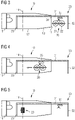
- Trolley 35 is then moved along the rail 31 towards the mounting position 14, as shown in figure 4 .
- the damping unit 20 is rotated, which will be explained in more detail further below.
- the damper unit 20 has reached the mounting position 14, it is mounted to the tower section 10.
- FIG. 5 illustrates the situation in which a first damper element 20 has been mounted to the tower section 10 and the trolley 35 has again been moved to its starting position.
- FIG 6 is a perspective view of the tower section 10 of figures 3-5 showing a situation in which two damper units 20 have been mounted inside the tower section 10 and a third damper unit 20 is suspended from the trolley 35 of the transport system 30.
- the damper unit 20 suspended from trolley 35 is oriented with its longitudinal direction substantially parallel to the longitudinal direction of the tower section 10 so that it fits through the opening at the top end 11 of the tower section 10.
- Trolley 35 is moved in a similar fashion into the tower section 10, the third damper unit 20 is rotated and is mounted to the tower section 10 at its mounting position, which is different from the mounting position of the first and second damper units.
- Figure 7 shows the situation after the third damper unit 20 has been mounted to the tower section 10 and the trolley has again been moved to the outside.
- the transport system 30 can now be disassembled and the tower section 10 can be transported to the installation site at which the wind turbine is to be erected. It should be clear that in other embodiments, only one or two damper units may be installed, or that more than three damper units may be installed.
- the damper unit 20 has an extension along its longitudinal direction 23 that is larger than the diameter at the opening in the top end 11 of the tower section 10. The same may apply to the bottom end 12, where a mounting flange for attaching the tower sections to each other may reduce the size of a respective opening.
- the size of the damper unit 20 in its longitudinal direction may for example be larger than 70%, 80% or even 85% of the inner diameter of the tower section 10 at the mounting position 14 to make good use of the space available inside the tower section 10.
- the damper unit 20 Prior to moving the damper unit 20 into the tower section 10, the damper unit 20 is thus rotated such that its longitudinal direction 23 is substantially parallel to the longitudinal direction 120 of the tower section 10 and to the direction of travel. It does not need to be exactly parallel - the purpose of rotating the damper unit 20 is that the damper unit 20 fits through the opening in the respective top or bottom end 11, 12 of the tower section 10.
- the rotated position of the damper unit 20 is illustrated in figure 8 .
- the damper unit is moved into the tower section 10.
- the damper unit 20 When located in the tower section 10, the damper unit 20 is rotated such that its longitudinal axis 23 is substantially perpendicular to the longitudinal axis 120 of the tower section 10, as shown in figure 9 .
- Rotation can occur at any suitable position inside the tower section 10; it may occur shortly behind the conical section 13 or close to or at the mounting position 14.
- Figure 10 illustrates the situation in which the damper unit 20 has been rotated and moved into its final position and has been mounted to the tower section 10.
- Such method of transporting the damping unit 20 into the tower section 10 can be used in combination with any of the assembly methods disclosed herein. It is in particular not limited to any particular configuration of the transport system 30.
- Figures 11 to 14 show a transport system according to a further embodiment of the invention.
- the transport system is a modification of the above described transport systems, so that above explanations are equally applicable to the transport system and assembly method of figures 11 to 13 .
- the transport system 30 shown in figure 11 includes a rail 31 and a trolley 35.
- the rail 31 is disposed in the lower half 15 of the tower section 10. In particular, it is supported in the tower section 10 by the outer shell 17 of the tower section 10.
- the transport system 30 comprises a first support 32 that supports the transport system 30, in particular the rail 31, outside the tower section 10.
- the first support 32 is provided by a leg or a pair of legs, but may have a different configuration.
- the transport system 30 is supported by one or more second supports 33, which again may be implemented as a leg or pair of legs that are standing on the shell 17 of the tower section 10.
- the second supports 33 are distributed along the longitudinal direction of the tower section 10 so that the rail 31 is sufficiently supported and is capable of carrying the weight of the damper unit 20.
- the rail 31 extends out of the tower section 10. In other embodiments, the rail may only extend inside the tower section 10.
- a ladder module 109 is further visible.
- the ladder module 109 is mounted in the upper half 16 of the tower section 10. If the damper until 20 is mounted in the lower half 15 of the tower section 10, there is sufficient space for leading the ladder module 109 past the damper unit 20 inside the tower section 10.
- the ladder module 109 may be present in any of the embodiments described herein. It may be mounted to the tower section 10 while the tower section 10 is oriented horizontally yet disposed upside down, i.e. with the upper half 16 facing downwards, as described in more detail further below.
- Figure 12 shows a close up view of the trolley 35.
- the trolley comprises a turn table 36 which can be hydraulically operated.
- the turn table 36 allows rotation of the damper unit 20 when the damper unit 20 is positioned on the trolley 35.
- the trolley 35 further comprises a mount 37, which has the shape of a bracket, but may have any other shape suitable for the respective damper unit 20.
- the rail 31 comprises two U-profiles on which the trolley 35 runs.
- the trolley 35 is equipped with respective wheels which run in the U-profiles.
- the rail 31 may comprise two bars, and the wheels of the trolley 35 may be notched to prevent the trolley from leaving the bars.
- the trolley is attached to a hauling rope 38, for example to steel wire.
- the trolley 35 can be moved by pulling the hauling rope 38.
- a pulley 40 is provided at the end of rail 31 that reverses the direction of the hauling rope 38 ( fig-ure 13 ).
- a winch 39 can be provided inside or preferably outside the tower section 10 to haul in the hauling rope 38 and to thereby move the trolley 35 into the tower section 10.
- the hauling rope 38 may be pulled out of the other end of the tower section 10.
- Figure 14 shows the situation in which the damper unit 20 is placed on the trolley 35.
- the damper unit 20 may be lifted by a hoist, a crane or the like onto the trolley 35 any may be held in place by the mount 37.
- the damper unit can be oriented with its longitudinal direction 23 parallel to the transport direction. Thereby, the damper unit 20 can be fitted easily into the tower section 10 even though a flange 50 at the bottom end 12 restricts the opening leading into the tower section 10.
- the damper unit 20 can include two damper elements 21, 22 that are secured to each other by means of a frame 25.
- the frame 25 can for example include two cross beams, one on each end face of the cylindrical damper elements 21, 22.
- the two beams fix the two damper elements to each other.
- the beams are preferably configured such that they provide a mounting structure for mounting of the damper unit to the tower section 10, in particular to an internal surface of the outer shell 17, for example using brackets or bolts.
- the ends of the beams may for example be shaped so as to be introduced into brackets mounted to the outer shell.
- the winch 39 is operated to pull the trolley and the damper unit 20 into the tower section 10.
- the turntable 36 is operated to rotate the damper unit 20 into the orientation required for mounting, as described above with respect to figures 8 to 10 .
- the trolley is then moved by actuation of the winch to the final mounting positon.
- the damping unit 20 is then mounted to the tower section 10, in particular to its outer shell 17, e.g. by fixing the cross beams thereto.
- damper units 20 can be mounted inside the tower section 10.
- the transport system 30 allows the mounting of the damper unit 20 at essentially any desired position inside the tower section 10.
- the damper unit 20 can be mounted close to the conical section 13 at the top end 11, even though it is introduced through the bottom end 12.
- Figure 15 is a flow diagram of a method of assembling a tower section in accordance with an embodiment of the invention. The method may be performed in accordance with any of the variations described above, in particular by employing a transport system in any of the above described configurations.
- step 201 the tower section 10 is arranged in a horizontal direction, as for example shown in figure 2 , 3 or 11 .
- a ladder module which may comprise several ladder elements, is mounted to the tower section 10.
- the ladder module is mounted inside the tower section 10 to the part of the outer shell 17 facing the ground.
- the ladder module 109 can thus simply be positioned inside the tower section 10 and fastened thereto.
- step 203 the tower section 10 is rotated around its longitudinal axis 120 (i.e. about its axial direction) by about 180 degrees so that the ladder module is disposed in the upper half 16 of the tower section 10, as shown in figure 11 .
- step 204 the horizontal transport system 30 is mounted to the tower section 10. This may for example occur by disposing the trolley 35 inside the tower section 10, by supporting a rail 31 in form of a beam inside the tower section 10, as shown in figure 3 , or by supporting a rail 31 in the lower half 15 of the tower section 10, as shown in figure 11 .
- variations are possible, for example with respect to the end of the tower section 10 into which the transport system 30 is introduced, the number and placement of supports for the rail 31 and the like.
- the damper unit 20 is attached to the trolley 35. It is for example disposed on the trolley and fastened thereto, or it is suspended from the trolley.
- the damper unit can be attached to the trolley in such way that its longitudinal axis is pointing in the direction of travel, i.e. is substantially parallel to the longitudinal direction of the tower section 10 (step 206).
- step 207 the damper unit is transported into the tower section via the respective end 11, 12 of the tower section 10.
- the trolley can for example be pulled by means of a wire cable, as described with respect to figures 11-14 .
- the trolley 35 or the damper unit 20 may be pushed.
- the damper unit 20 is rotated into the mounting orientation in which it is to be mounted, as described with respect to figures 8 to 10 (step 208). Rotation may occur via the turntable.
- a similar rotating mechanism may be included in the trolley of figures 3-7 .
- the damper unit is positioned at the final mounting position (step 209).
- the damper unit 20 is then mounted to the tower section 10 in step 210.
- bars of the frame 25 supporting the damper elements 21, 22 may be directly attached to a wall of the tower section 10 using bolts or the like.
- step 211 the horizontal transport system 30 is removed from the tower section 10.
- the trolley and any rail and supports are for example removed.
- Further assembly steps can be carried out subsequently, such as the installation of platforms in the tower section 10 in step 212.
- the tower section 10 is preferably a top section, respective top section platforms are installed.
- the sections can be installed by a telescopic handler, as they have a comparatively low weight. It should be clear that prior to or after installing the damper unit 20 in the tower section 10, any additional assembly steps can be performed as required and as are typical for the assembly of a wind turbine tower section, such as the installation of the ladder and the platforms, installation of cable holders, installation of equipment on a platform and the like.
- step 213 the tower section 10 is transported to an installation site of the wind turbine, i.e. to the place where the wind turbine is to be erected. Transport may occur using vehicles and boats.
- the tower section 10 is generally not rotated again (around its longitudinal axis) when loading the tower section 10 from the assembly site onto a transport vehicle, such as a trailer.
- a transport vehicle such as a trailer.
- the one or more damper units 20 are mounted in the lower half 15 of the wind turbine tower section 10, tendency of the tower section 10 to roll over is significantly reduced due to the low center of gravity. Imbalances during transport on boats and the rolling or swaying of a trailer during transport on the road may thus be avoided.
- the wind turbine tower 101 is for example erected by placing the tower sections 111, 112, 10 on top of each other, wherein section 10 is the top section. Using flanges 50 ( figure 16 ), the tower sections are mounted to each other. A yaw system and the nacelle 102 can then be mounted on top of the tower section 10 (see figure 1 ). Accordingly, a safe and efficient way of assembling the tower section 10 and the wind turbine 100 is provided.
- steps 202 to 204, 206, 208, and 211-213 are optional, such as steps 202 to 204, 206, 208, and 211-213.
- Figure 16 shows a view from the bottom end 12 of the tower section 10 in which the damper unit 20 is installed.
- the flange 50 at the bottom end 12 and the flange 19 at the top end 11 of the tower section 10 are visible.
- the longitudinal extension of the damper unit 20 is such that it does not fit through the opening in top end 11 when oriented laterally.
- the damper unit 20 is mounted to an inner side of the wall or outer shell 17 by means of the frame 25, for example by fastening the cross beams directly to the wall of the tower section 10. Further mounting elements 27 can be provided to ensure a stable and secure attachment to the outer shell 17.
- the dashed line in figure 16 indicates a substantially horizontal plane that includes the central symmetry axis in longitudinal direction (the cylinder axis or cone axis) of the tower section 10 and that divides the tower section 10 into the upper half 16 and the lower half 15.
- the upper half 16 there is sufficient space available for placement of a ladder and other equipment, such as cables and the like.
- a circle segment of at least 90 degrees, preferably at least 120 degrees is not occupied by the damper unit 20, it is possible to mount equipment to the outer shell 17 of the tower section 10 in this area.
- the damper unit 20 By including two cylindrical damper elements 21, 22 in the damper unit 20, the space around the central axis of the tower section 10 can in particular be kept free.
- damper unit By installing the damper unit in the lower half of the tower section, a low center of gravity of the tower section is achieved. Further, the assembly methods allow the introduction of the large damper unit that comprises two damper elements supported by a double beam frame into the tower section, even though the extension of such structure is generally larger than the width of the end openings of the tower section.
- the assembly method and transport system allow introduction of the damper unit into the tower section from either side, and the damper unit can be introduced at the bottom end even though it is to be mounted close to the top end of the tower section.
- damper units having a significant weight for example 8 t or more, may be installed at any desirable position along the tower section by the assembly methods and the transport systems described herein.
Landscapes
- Engineering & Computer Science (AREA)
- General Engineering & Computer Science (AREA)
- Mechanical Engineering (AREA)
- Sustainable Energy (AREA)
- Chemical & Material Sciences (AREA)
- Combustion & Propulsion (AREA)
- Life Sciences & Earth Sciences (AREA)
- Sustainable Development (AREA)
- Transportation (AREA)
- Physics & Mathematics (AREA)
- Acoustics & Sound (AREA)
- Aviation & Aerospace Engineering (AREA)
- Wind Motors (AREA)
Claims (9)
- Procédé d'assemblage d'une section de tour (10) d'une tour d'éolienne (101), comprenant les étapes de- l'agencement de la section de tour (10) de la tour d'éolienne (101) dans une orientation horizontale ;- le transport d'une unité d'amortissement (20) jusqu'à une position à l'intérieur de la section de tour (10) tandis que la section de tour (10) est agencée dans l'orientation horizontale ; et- le montage de l'unité d'amortissement (20) sur la section de tour (10), dans lequel l'unité d'amortissement est configurée pour amortir des mouvements de la tour d'éolienne (101) ,dans lequel l'unité d'amortissement (20) s'étend dans une direction longitudinale (23),
caractérisé en ce que le transport de l'unité d'amortissement (20) dans la section de tour (10) comprend- l'orientation de l'unité d'amortissement (20) de sorte que sa direction longitudinale (23) soit sensiblement parallèle à une direction de transport horizontale ;- le transport de l'unité d'amortissement (20) le long de la direction de transport horizontale jusqu'à une position à l'intérieur de la section de tour (10) ; et- la rotation de l'unité d'amortissement (20) tandis que l'unité d'amortissement est située à l'intérieur de la section de tour (10) de sorte que sa direction longitudinale (23) soit sensiblement perpendiculaire à la direction de transport horizontale. - Procédé selon la revendication 1, dans lequel le transport de l'unité d'amortissement (20) dans la section de tour (10) comprend l'emploi d'un système de transport horizontal (30) pour transporter l'unité d'amortissement (20) dans une direction horizontale jusqu'à une position à l'intérieur de la section de tour (10), dans lequel le système de transport horizontal (30) est soutenu au moins à une position par la section de tour (10).
- Procédé selon la revendication 2, dans lequel le système de transport horizontal (30) est sur un côté soutenu par la section de tour (10) et est sur le côté opposé soutenu à l'extérieur de la section de tour (10), dans lequel le montage de l'unité d'amortissement (20) dans la section de tour (10) comprend le transport de l'unité d'amortissement (20) d'une position à l'extérieur de la section de tour (10) à la position à l'intérieur de la section de tour (10) à l'aide du système de transport horizontal (30).
- Procédé selon la revendication 2 ou 3, dans lequel le système de transport horizontal (30) comprend un chariot (35), dans lequel le montage de l'unité d'amortissement (20) dans la section de tour (10) comprend le soutien de l'unité d'amortissement par le chariot (35) et le déplacement du chariot (35) pour transporter l'unité d'amortissement (20) dans la direction horizontale jusqu'à ladite position.
- Procédé selon l'une quelconque des revendications précédentes, dans lequel le transport de l'unité d'amortissement (20) jusqu'à une position à l'intérieur de la section de tour (10) comprend le transport de l'unité d'amortissement jusqu'à une position à l'intérieur de la section de tour qui est espacée de chaque extrémité (11, 12) de la section de tour (10) d'au moins 4 m, de préférence d'au moins 6 m, plus préférentiellement d'au moins 8 m.
- Procédé selon l'une quelconque des revendications précédentes, dans lequel le procédé comprend en outre, avant le transport de l'unité d'amortissement (20) jusqu'à une position à l'intérieur de la section de tour (10) :- l'installation d'un module d'échelle (109) dans la section de tour (10) ; et- la rotation de la section de tour (10) d'environ 180 degrés autour de son axe longitudinal central (120) de sorte que le module d'échelle (109) soit agencé dans une partie supérieure (16) de la section de tour (10).
- Système de transport horizontal pour l'assemblage d'une section de tour (10) d'une tour d'éolienne, dans lequel le système de transport horizontal (30) est configuré pour être soutenu au moins à une position par la section de tour (10) et comprend un chariot (35) configuré pour soutenir une unité d'amortissement (20) et pour transporter l'unité d'amortissement (20) dans une direction horizontale, d'une position adjacente à une extrémité (11, 12) de la section de tour (10) à une position au niveau d'une position de montage (14), ou adjacente à celle-ci, de l'unité d'amortissement (20) à l'intérieur de la section de tour (10) tandis que la section de tour (10) est agencée dans une orientation horizontale,dans lequel l'unité d'amortissement (20) s'étend dans une direction longitudinale (23),caractérisé en ce quele chariot (35) comprend un élément rotatif configuré pour effectuer la rotation de l'unité d'amortissement tandis que l'unité d'amortissement est soutenue par le chariot de sorte que l'unité d'amortissement (20) soit transportable dans la section de tour (10) par l'orientation de l'unité d'amortissement (20) d'une manière telle que sa direction longitudinale (23) soit sensiblement parallèle à une direction de transport horizontale, le transport de l'unité d'amortissement (20) le long de la direction de transport horizontale jusqu'à la position à l'intérieur de la section de tour (10) au moyen dudit chariot (35), et la rotation, par l'élément rotatif du chariot (35), de l'unité d'amortissement (20) tandis que l'unité d'amortissement est située à l'intérieur de la section de tour (10) de sorte que sa direction longitudinale (23) soit sensiblement perpendiculaire à la direction de transport horizontale.
- Système de transport horizontal selon la revendication 7, dans lequel le système de transport horizontal (30) comprend un rail (31), dans lequel le chariot (35) est configuré pour rouler sur le rail (31), dans lequel le rail (31) est un rail inférieur disposé dans une partie basse (15) de la section de tour (10) lorsque la section de tour (10) est dans l'orientation horizontale, et dans lequel le chariot (35) est configuré pour porter l'unité d'amortissement et est en outre configuré de sorte que l'unité d'amortissement (20) soit apte à être placée sur le dessus du chariot (35).
- Système de transport horizontal selon la revendication 7, dans lequel le système de transport horizontal comprend un rail (31), dans lequel le chariot (35) est configuré pour rouler sur le rail (31), dans lequel le rail (31) est une poutre disposée dans une partie haute (16) de la section de tour (10) lorsque la section de tour (10) est dans l'orientation horizontale, et dans lequel le chariot (35) est configuré de sorte que l'unité d'amortissement (20) soit apte à être suspendue au chariot (35).
Priority Applications (4)
| Application Number | Priority Date | Filing Date | Title |
|---|---|---|---|
| DK19161312.4T DK3705718T3 (da) | 2019-03-07 | 2019-03-07 | Samling af en tårnsektion af et vindmølletårn |
| EP19161312.4A EP3705718B1 (fr) | 2019-03-07 | 2019-03-07 | Assemblage d'une section de tour d'une éolienne |
| US16/804,034 US11585405B2 (en) | 2019-03-07 | 2020-02-28 | Assembly of a tower section of a wind turbine tower |
| CN202010151801.3A CN111664059B (zh) | 2019-03-07 | 2020-03-06 | 风力涡轮机塔架的塔架区段的组装 |
Applications Claiming Priority (1)
| Application Number | Priority Date | Filing Date | Title |
|---|---|---|---|
| EP19161312.4A EP3705718B1 (fr) | 2019-03-07 | 2019-03-07 | Assemblage d'une section de tour d'une éolienne |
Publications (2)
| Publication Number | Publication Date |
|---|---|
| EP3705718A1 EP3705718A1 (fr) | 2020-09-09 |
| EP3705718B1 true EP3705718B1 (fr) | 2022-08-17 |
Family
ID=65724270
Family Applications (1)
| Application Number | Title | Priority Date | Filing Date |
|---|---|---|---|
| EP19161312.4A Active EP3705718B1 (fr) | 2019-03-07 | 2019-03-07 | Assemblage d'une section de tour d'une éolienne |
Country Status (4)
| Country | Link |
|---|---|
| US (1) | US11585405B2 (fr) |
| EP (1) | EP3705718B1 (fr) |
| CN (1) | CN111664059B (fr) |
| DK (1) | DK3705718T3 (fr) |
Families Citing this family (5)
| Publication number | Priority date | Publication date | Assignee | Title |
|---|---|---|---|---|
| CN107906165B (zh) * | 2017-11-09 | 2023-11-14 | 大连理工大学 | 一种适用于海上单桩式风机安装的主动式阻尼装置 |
| EP4065838B1 (fr) | 2019-11-26 | 2024-05-22 | Vestas Wind Systems A/S | Installation de câbles et autres composants dans une tour d'éolienne |
| EP3889457A1 (fr) * | 2020-04-03 | 2021-10-06 | Siemens Gamesa Renewable Energy A/S | Ensemble amortisseur temporaire |
| EP3901455A1 (fr) * | 2020-04-23 | 2021-10-27 | Siemens Gamesa Renewable Energy A/S | Éolienne |
| CN121712982A (zh) | 2023-08-22 | 2026-03-20 | 维斯塔斯风力系统有限公司 | 用于将至少一个阻尼器单元安装在风力涡轮机的塔架区段中的方法和套件 |
Citations (6)
| Publication number | Priority date | Publication date | Assignee | Title |
|---|---|---|---|---|
| US4937929A (en) | 1986-09-25 | 1990-07-03 | Honda Giken Kogyo Kabushiki Kaisha | Method and apparatus for transporting vehicle bodies, and vehicle assembling system |
| WO2011055021A2 (fr) | 2009-11-09 | 2011-05-12 | Terästorni Oy | Procédé et dispositif pour assembler une centrale éolienne |
| DE102009055726A1 (de) | 2009-11-26 | 2011-06-01 | Aerodyn Engineering Gmbh | Inneneinbauelement für den Rohrturm einer Windenergieanlage |
| CN102828922A (zh) | 2012-08-22 | 2012-12-19 | 上海泰胜风能装备股份有限公司 | 风力机塔筒减震摆锤的安装装置 |
| WO2014206840A1 (fr) | 2013-06-27 | 2014-12-31 | Senvion Se | Système de remplacement de transformateurs |
| US20170138351A1 (en) | 2015-11-06 | 2017-05-18 | Hitachi, Ltd. | Offshore Wind Turbine, Method for Constructing Offshore Wind Turbine, and Offshore Wind Power Generator |
Family Cites Families (14)
| Publication number | Priority date | Publication date | Assignee | Title |
|---|---|---|---|---|
| DE10054821A1 (de) * | 2000-11-04 | 2002-05-23 | Wittenstein Gmbh & Co Kg | Verfahren und Vorrichtung zum Beladen eines Flugzeuges |
| US20060275121A1 (en) * | 2003-04-17 | 2006-12-07 | Merswolka Paul H/F And Meyer Charles F | Wind turbine with friction drive power take off on outer rim |
| US7097029B2 (en) * | 2004-12-23 | 2006-08-29 | Krones Ag. | Parcel goods aligning device |
| DE102005008443B4 (de) * | 2005-02-24 | 2009-06-18 | Airbus Deutschland Gmbh | Ladevorrichtung zum zumindest teilautomatischen Beladen und Entladen eines Frachtraums eines Verkehrsmittels |
| EA201190212A1 (ru) * | 2009-03-11 | 2012-07-30 | Илья Харковер | Модульная система хранения |
| KR101116716B1 (ko) * | 2010-04-14 | 2012-03-05 | 다이후쿠코리아 (주) | 자전거주차설비용 자전거운반주차장치 |
| WO2012098161A1 (fr) * | 2011-01-19 | 2012-07-26 | Telair International Gmbh | Système de chargement d'un avion et procédé de transport d'une marchandise de fret sur une plate-forme de chargement. |
| DK2899397T3 (en) | 2014-01-28 | 2017-04-10 | Siemens Ag | Attenuator of a wind turbine |
| DE102015000787A1 (de) * | 2015-01-26 | 2016-07-28 | Senvion Gmbh | Lastaufnahmemittel für einen Turm oder eine Turmsektion einer Windenergieanlage und Verfahren zum Errichten einer Windenergieanlage |
| DE102015013098A1 (de) * | 2015-10-12 | 2017-04-13 | Senvion Gmbh | Verfahren zum Einbau eines Pendeldämpfers in eine Windenergieanlage, Befüllungssystem und Windenergieanlage |
| US11603821B2 (en) * | 2017-08-08 | 2023-03-14 | Fm Energie Gmbh & Co. Kg | Rotation damper and vibration absorber equipped therewith |
| ES2856923T3 (es) * | 2017-11-02 | 2021-09-28 | Soletanche Freyssinet | Dispositivo para amortiguar las vibraciones en una estructura y uso del dispositivo |
| EP3814628B1 (fr) * | 2018-06-29 | 2023-08-02 | Vestas Wind Systems A/S | Unité d'amortissement pour structure de tour |
| DE102018005852A1 (de) * | 2018-07-25 | 2020-01-30 | Senvion Gmbh | Montageverfahren und Montagesystem für einen Schwingungsdämpfer eines Windenergieanlagenturms |
-
2019
- 2019-03-07 EP EP19161312.4A patent/EP3705718B1/fr active Active
- 2019-03-07 DK DK19161312.4T patent/DK3705718T3/da active
-
2020
- 2020-02-28 US US16/804,034 patent/US11585405B2/en active Active
- 2020-03-06 CN CN202010151801.3A patent/CN111664059B/zh active Active
Patent Citations (6)
| Publication number | Priority date | Publication date | Assignee | Title |
|---|---|---|---|---|
| US4937929A (en) | 1986-09-25 | 1990-07-03 | Honda Giken Kogyo Kabushiki Kaisha | Method and apparatus for transporting vehicle bodies, and vehicle assembling system |
| WO2011055021A2 (fr) | 2009-11-09 | 2011-05-12 | Terästorni Oy | Procédé et dispositif pour assembler une centrale éolienne |
| DE102009055726A1 (de) | 2009-11-26 | 2011-06-01 | Aerodyn Engineering Gmbh | Inneneinbauelement für den Rohrturm einer Windenergieanlage |
| CN102828922A (zh) | 2012-08-22 | 2012-12-19 | 上海泰胜风能装备股份有限公司 | 风力机塔筒减震摆锤的安装装置 |
| WO2014206840A1 (fr) | 2013-06-27 | 2014-12-31 | Senvion Se | Système de remplacement de transformateurs |
| US20170138351A1 (en) | 2015-11-06 | 2017-05-18 | Hitachi, Ltd. | Offshore Wind Turbine, Method for Constructing Offshore Wind Turbine, and Offshore Wind Power Generator |
Also Published As
| Publication number | Publication date |
|---|---|
| CN111664059A (zh) | 2020-09-15 |
| CN111664059B (zh) | 2023-11-10 |
| US11585405B2 (en) | 2023-02-21 |
| US20200284315A1 (en) | 2020-09-10 |
| EP3705718A1 (fr) | 2020-09-09 |
| DK3705718T3 (da) | 2022-09-12 |
Similar Documents
| Publication | Publication Date | Title |
|---|---|---|
| EP3705718B1 (fr) | Assemblage d'une section de tour d'une éolienne | |
| EP3048299B1 (fr) | Moyen de suspension de charge pour une tour ou une section de tour d'une eolienne et procede de montage d'une eolienne | |
| EP3063405B1 (fr) | Procédé d'amortissement d'oscillations de tour de turbine éolienne | |
| JP6921086B2 (ja) | マルチローター風力タービンの風力タービンコンポーネントを据付け又は撤去する方法 | |
| KR102168734B1 (ko) | 풍력 터빈의 회전자 블레이드를 배치하기 위한 장치 및 방법 | |
| US20210207393A1 (en) | Tower erection and climbing systems | |
| EP2805048B1 (fr) | Système d'érection de tour d'éolienne | |
| JP6833853B2 (ja) | マルチローター風力タービンの風力タービンコンポーネントを据付け又は撤去する方法 | |
| EP3311024B1 (fr) | Ensemble de hissage portable et modulaire pour une éolienne | |
| JP6923670B2 (ja) | 風力タービン設置用巻き上げシステム | |
| EP1677006A2 (fr) | Eolienne avec une grue détachable | |
| CN101737273A (zh) | 塔架、风力发电机组以及在塔架内设置平台的方法 | |
| US10815687B2 (en) | Wind turbine assembly system and associated method | |
| EP2278157A2 (fr) | Tour d'éolienne transportable par train | |
| WO2014040598A1 (fr) | Procédé d'amortissement des oscillations de tour d'éolienne | |
| CN102701083A (zh) | 风力发电机部件更换专用设备及方法 | |
| CN107923361A (zh) | 移动风轮机部件的方法及用于移动风轮机部件的运输系统 | |
| CN101535582A (zh) | 用于构建和包覆风力涡轮机塔架的提升系统及装置 | |
| CN103935868A (zh) | 一种塔筒升降机 | |
| CN113653600A (zh) | 塔架部段布置结构、拉索式风力涡轮机塔架、风力涡轮机以及用于组装风力涡轮机的方法 | |
| CN120513345A (zh) | 用于风力涡轮机组装系统的提升系统及相关的提升方法 | |
| EP4345292A1 (fr) | Adaptateur, tour comprenant l'adaptateur et éolienne comprenant la tour et parc éolien comprenant au moins une éolienne | |
| JP2024543162A (ja) | 風力タービンブレード設置システム及び関連する方法 | |
| CN118715172A (zh) | 自爬升塔式起重机 | |
| CN214089423U (zh) | 一种拱桥用吊装塔 |
Legal Events
| Date | Code | Title | Description |
|---|---|---|---|
| PUAI | Public reference made under article 153(3) epc to a published international application that has entered the european phase |
Free format text: ORIGINAL CODE: 0009012 |
|
| STAA | Information on the status of an ep patent application or granted ep patent |
Free format text: STATUS: THE APPLICATION HAS BEEN PUBLISHED |
|
| AK | Designated contracting states |
Kind code of ref document: A1 Designated state(s): AL AT BE BG CH CY CZ DE DK EE ES FI FR GB GR HR HU IE IS IT LI LT LU LV MC MK MT NL NO PL PT RO RS SE SI SK SM TR |
|
| STAA | Information on the status of an ep patent application or granted ep patent |
Free format text: STATUS: REQUEST FOR EXAMINATION WAS MADE |
|
| 17P | Request for examination filed |
Effective date: 20201103 |
|
| RBV | Designated contracting states (corrected) |
Designated state(s): AL AT BE BG CH CY CZ DE DK EE ES FI FR GB GR HR HU IE IS IT LI LT LU LV MC MK MT NL NO PL PT RO RS SE SI SK SM TR |
|
| GRAP | Despatch of communication of intention to grant a patent |
Free format text: ORIGINAL CODE: EPIDOSNIGR1 |
|
| STAA | Information on the status of an ep patent application or granted ep patent |
Free format text: STATUS: GRANT OF PATENT IS INTENDED |
|
| INTG | Intention to grant announced |
Effective date: 20220414 |
|
| GRAS | Grant fee paid |
Free format text: ORIGINAL CODE: EPIDOSNIGR3 |
|
| GRAA | (expected) grant |
Free format text: ORIGINAL CODE: 0009210 |
|
| STAA | Information on the status of an ep patent application or granted ep patent |
Free format text: STATUS: THE PATENT HAS BEEN GRANTED |
|
| AK | Designated contracting states |
Kind code of ref document: B1 Designated state(s): AL AT BE BG CH CY CZ DE DK EE ES FI FR GB GR HR HU IE IS IT LI LT LU LV MC MK MT NL NO PL PT RO RS SE SI SK SM TR |
|
| REG | Reference to a national code |
Ref country code: CH Ref legal event code: EP |
|
| REG | Reference to a national code |
Ref country code: DE Ref legal event code: R096 Ref document number: 602019018269 Country of ref document: DE |
|
| REG | Reference to a national code |
Ref country code: DK Ref legal event code: T3 Effective date: 20220907 |
|
| REG | Reference to a national code |
Ref country code: IE Ref legal event code: FG4D |
|
| REG | Reference to a national code |
Ref country code: AT Ref legal event code: REF Ref document number: 1512353 Country of ref document: AT Kind code of ref document: T Effective date: 20220915 |
|
| REG | Reference to a national code |
Ref country code: NL Ref legal event code: FP |
|
| REG | Reference to a national code |
Ref country code: LT Ref legal event code: MG9D |
|
| PG25 | Lapsed in a contracting state [announced via postgrant information from national office to epo] |
Ref country code: SE Free format text: LAPSE BECAUSE OF FAILURE TO SUBMIT A TRANSLATION OF THE DESCRIPTION OR TO PAY THE FEE WITHIN THE PRESCRIBED TIME-LIMIT Effective date: 20220817 Ref country code: RS Free format text: LAPSE BECAUSE OF FAILURE TO SUBMIT A TRANSLATION OF THE DESCRIPTION OR TO PAY THE FEE WITHIN THE PRESCRIBED TIME-LIMIT Effective date: 20220817 Ref country code: PT Free format text: LAPSE BECAUSE OF FAILURE TO SUBMIT A TRANSLATION OF THE DESCRIPTION OR TO PAY THE FEE WITHIN THE PRESCRIBED TIME-LIMIT Effective date: 20221219 Ref country code: NO Free format text: LAPSE BECAUSE OF FAILURE TO SUBMIT A TRANSLATION OF THE DESCRIPTION OR TO PAY THE FEE WITHIN THE PRESCRIBED TIME-LIMIT Effective date: 20221117 Ref country code: LV Free format text: LAPSE BECAUSE OF FAILURE TO SUBMIT A TRANSLATION OF THE DESCRIPTION OR TO PAY THE FEE WITHIN THE PRESCRIBED TIME-LIMIT Effective date: 20220817 Ref country code: LT Free format text: LAPSE BECAUSE OF FAILURE TO SUBMIT A TRANSLATION OF THE DESCRIPTION OR TO PAY THE FEE WITHIN THE PRESCRIBED TIME-LIMIT Effective date: 20220817 Ref country code: FI Free format text: LAPSE BECAUSE OF FAILURE TO SUBMIT A TRANSLATION OF THE DESCRIPTION OR TO PAY THE FEE WITHIN THE PRESCRIBED TIME-LIMIT Effective date: 20220817 |
|
| REG | Reference to a national code |
Ref country code: AT Ref legal event code: MK05 Ref document number: 1512353 Country of ref document: AT Kind code of ref document: T Effective date: 20220817 |
|
| PG25 | Lapsed in a contracting state [announced via postgrant information from national office to epo] |
Ref country code: PL Free format text: LAPSE BECAUSE OF FAILURE TO SUBMIT A TRANSLATION OF THE DESCRIPTION OR TO PAY THE FEE WITHIN THE PRESCRIBED TIME-LIMIT Effective date: 20220817 Ref country code: IS Free format text: LAPSE BECAUSE OF FAILURE TO SUBMIT A TRANSLATION OF THE DESCRIPTION OR TO PAY THE FEE WITHIN THE PRESCRIBED TIME-LIMIT Effective date: 20221217 Ref country code: HR Free format text: LAPSE BECAUSE OF FAILURE TO SUBMIT A TRANSLATION OF THE DESCRIPTION OR TO PAY THE FEE WITHIN THE PRESCRIBED TIME-LIMIT Effective date: 20220817 Ref country code: GR Free format text: LAPSE BECAUSE OF FAILURE TO SUBMIT A TRANSLATION OF THE DESCRIPTION OR TO PAY THE FEE WITHIN THE PRESCRIBED TIME-LIMIT Effective date: 20221118 |
|
| PG25 | Lapsed in a contracting state [announced via postgrant information from national office to epo] |
Ref country code: SM Free format text: LAPSE BECAUSE OF FAILURE TO SUBMIT A TRANSLATION OF THE DESCRIPTION OR TO PAY THE FEE WITHIN THE PRESCRIBED TIME-LIMIT Effective date: 20220817 Ref country code: RO Free format text: LAPSE BECAUSE OF FAILURE TO SUBMIT A TRANSLATION OF THE DESCRIPTION OR TO PAY THE FEE WITHIN THE PRESCRIBED TIME-LIMIT Effective date: 20220817 Ref country code: ES Free format text: LAPSE BECAUSE OF FAILURE TO SUBMIT A TRANSLATION OF THE DESCRIPTION OR TO PAY THE FEE WITHIN THE PRESCRIBED TIME-LIMIT Effective date: 20220817 Ref country code: CZ Free format text: LAPSE BECAUSE OF FAILURE TO SUBMIT A TRANSLATION OF THE DESCRIPTION OR TO PAY THE FEE WITHIN THE PRESCRIBED TIME-LIMIT Effective date: 20220817 Ref country code: AT Free format text: LAPSE BECAUSE OF FAILURE TO SUBMIT A TRANSLATION OF THE DESCRIPTION OR TO PAY THE FEE WITHIN THE PRESCRIBED TIME-LIMIT Effective date: 20220817 |
|
| REG | Reference to a national code |
Ref country code: DE Ref legal event code: R026 Ref document number: 602019018269 Country of ref document: DE |
|
| PLBI | Opposition filed |
Free format text: ORIGINAL CODE: 0009260 |
|
| PLAB | Opposition data, opponent's data or that of the opponent's representative modified |
Free format text: ORIGINAL CODE: 0009299OPPO |
|
| PG25 | Lapsed in a contracting state [announced via postgrant information from national office to epo] |
Ref country code: SK Free format text: LAPSE BECAUSE OF FAILURE TO SUBMIT A TRANSLATION OF THE DESCRIPTION OR TO PAY THE FEE WITHIN THE PRESCRIBED TIME-LIMIT Effective date: 20220817 Ref country code: EE Free format text: LAPSE BECAUSE OF FAILURE TO SUBMIT A TRANSLATION OF THE DESCRIPTION OR TO PAY THE FEE WITHIN THE PRESCRIBED TIME-LIMIT Effective date: 20220817 |
|
| PLAX | Notice of opposition and request to file observation + time limit sent |
Free format text: ORIGINAL CODE: EPIDOSNOBS2 |
|
| 26 | Opposition filed |
Opponent name: VESTAS WIND SYSTEMS A/S Effective date: 20230517 |
|
| R26 | Opposition filed (corrected) |
Opponent name: VESTAS WIND SYSTEMS A/S Effective date: 20230517 |
|
| PG25 | Lapsed in a contracting state [announced via postgrant information from national office to epo] |
Ref country code: AL Free format text: LAPSE BECAUSE OF FAILURE TO SUBMIT A TRANSLATION OF THE DESCRIPTION OR TO PAY THE FEE WITHIN THE PRESCRIBED TIME-LIMIT Effective date: 20220817 |
|
| PG25 | Lapsed in a contracting state [announced via postgrant information from national office to epo] |
Ref country code: SI Free format text: LAPSE BECAUSE OF FAILURE TO SUBMIT A TRANSLATION OF THE DESCRIPTION OR TO PAY THE FEE WITHIN THE PRESCRIBED TIME-LIMIT Effective date: 20220817 |
|
| PLBB | Reply of patent proprietor to notice(s) of opposition received |
Free format text: ORIGINAL CODE: EPIDOSNOBS3 |
|
| PG25 | Lapsed in a contracting state [announced via postgrant information from national office to epo] |
Ref country code: MC Free format text: LAPSE BECAUSE OF FAILURE TO SUBMIT A TRANSLATION OF THE DESCRIPTION OR TO PAY THE FEE WITHIN THE PRESCRIBED TIME-LIMIT Effective date: 20220817 |
|
| REG | Reference to a national code |
Ref country code: CH Ref legal event code: PL |
|
| REG | Reference to a national code |
Ref country code: BE Ref legal event code: MM Effective date: 20230331 |
|
| PG25 | Lapsed in a contracting state [announced via postgrant information from national office to epo] |
Ref country code: LU Free format text: LAPSE BECAUSE OF NON-PAYMENT OF DUE FEES Effective date: 20230307 |
|
| REG | Reference to a national code |
Ref country code: IE Ref legal event code: MM4A |
|
| PG25 | Lapsed in a contracting state [announced via postgrant information from national office to epo] |
Ref country code: LI Free format text: LAPSE BECAUSE OF NON-PAYMENT OF DUE FEES Effective date: 20230331 Ref country code: IE Free format text: LAPSE BECAUSE OF NON-PAYMENT OF DUE FEES Effective date: 20230307 Ref country code: CH Free format text: LAPSE BECAUSE OF NON-PAYMENT OF DUE FEES Effective date: 20230331 |
|
| PG25 | Lapsed in a contracting state [announced via postgrant information from national office to epo] |
Ref country code: BE Free format text: LAPSE BECAUSE OF NON-PAYMENT OF DUE FEES Effective date: 20230331 |
|
| PG25 | Lapsed in a contracting state [announced via postgrant information from national office to epo] |
Ref country code: IT Free format text: LAPSE BECAUSE OF FAILURE TO SUBMIT A TRANSLATION OF THE DESCRIPTION OR TO PAY THE FEE WITHIN THE PRESCRIBED TIME-LIMIT Effective date: 20220817 |
|
| PG25 | Lapsed in a contracting state [announced via postgrant information from national office to epo] |
Ref country code: BG Free format text: LAPSE BECAUSE OF FAILURE TO SUBMIT A TRANSLATION OF THE DESCRIPTION OR TO PAY THE FEE WITHIN THE PRESCRIBED TIME-LIMIT Effective date: 20220817 |
|
| PG25 | Lapsed in a contracting state [announced via postgrant information from national office to epo] |
Ref country code: BG Free format text: LAPSE BECAUSE OF FAILURE TO SUBMIT A TRANSLATION OF THE DESCRIPTION OR TO PAY THE FEE WITHIN THE PRESCRIBED TIME-LIMIT Effective date: 20220817 |
|
| PLCK | Communication despatched that opposition was rejected |
Free format text: ORIGINAL CODE: EPIDOSNREJ1 |
|
| APBP | Date of receipt of notice of appeal recorded |
Free format text: ORIGINAL CODE: EPIDOSNNOA2O |
|
| APAH | Appeal reference modified |
Free format text: ORIGINAL CODE: EPIDOSCREFNO |
|
| APAW | Appeal reference deleted |
Free format text: ORIGINAL CODE: EPIDOSDREFNO |
|
| PG25 | Lapsed in a contracting state [announced via postgrant information from national office to epo] |
Ref country code: CY Free format text: LAPSE BECAUSE OF FAILURE TO SUBMIT A TRANSLATION OF THE DESCRIPTION OR TO PAY THE FEE WITHIN THE PRESCRIBED TIME-LIMIT; INVALID AB INITIO Effective date: 20190307 |
|
| PG25 | Lapsed in a contracting state [announced via postgrant information from national office to epo] |
Ref country code: HU Free format text: LAPSE BECAUSE OF FAILURE TO SUBMIT A TRANSLATION OF THE DESCRIPTION OR TO PAY THE FEE WITHIN THE PRESCRIBED TIME-LIMIT; INVALID AB INITIO Effective date: 20190307 |
|
| APBQ | Date of receipt of statement of grounds of appeal recorded |
Free format text: ORIGINAL CODE: EPIDOSNNOA3O |
|
| PG25 | Lapsed in a contracting state [announced via postgrant information from national office to epo] |
Ref country code: TR Free format text: LAPSE BECAUSE OF FAILURE TO SUBMIT A TRANSLATION OF THE DESCRIPTION OR TO PAY THE FEE WITHIN THE PRESCRIBED TIME-LIMIT Effective date: 20220817 |
|
| PGFP | Annual fee paid to national office [announced via postgrant information from national office to epo] |
Ref country code: GB Payment date: 20260323 Year of fee payment: 8 |
|
| PGFP | Annual fee paid to national office [announced via postgrant information from national office to epo] |
Ref country code: DK Payment date: 20260323 Year of fee payment: 8 Ref country code: DE Payment date: 20250731 Year of fee payment: 8 |
|
| PGFP | Annual fee paid to national office [announced via postgrant information from national office to epo] |
Ref country code: NL Payment date: 20260323 Year of fee payment: 8 |
|
| PGFP | Annual fee paid to national office [announced via postgrant information from national office to epo] |
Ref country code: FR Payment date: 20260323 Year of fee payment: 8 |