EP3705786B1 - Module d'intégration des générateurs de chaleur dans un système de chauffage - Google Patents
Module d'intégration des générateurs de chaleur dans un système de chauffage Download PDFInfo
- Publication number
- EP3705786B1 EP3705786B1 EP20401015.1A EP20401015A EP3705786B1 EP 3705786 B1 EP3705786 B1 EP 3705786B1 EP 20401015 A EP20401015 A EP 20401015A EP 3705786 B1 EP3705786 B1 EP 3705786B1
- Authority
- EP
- European Patent Office
- Prior art keywords
- heat
- heat generator
- module
- heating system
- connections
- Prior art date
- Legal status (The legal status is an assumption and is not a legal conclusion. Google has not performed a legal analysis and makes no representation as to the accuracy of the status listed.)
- Active
Links
Images



Classifications
-
- F—MECHANICAL ENGINEERING; LIGHTING; HEATING; WEAPONS; BLASTING
- F24—HEATING; RANGES; VENTILATING
- F24D—DOMESTIC- OR SPACE-HEATING SYSTEMS, e.g. CENTRAL HEATING SYSTEMS; DOMESTIC HOT-WATER SUPPLY SYSTEMS; ELEMENTS OR COMPONENTS THEREFOR
- F24D3/00—Hot-water central heating systems
- F24D3/10—Feed-line arrangements, e.g. providing for heat-accumulator tanks, expansion tanks ; Hydraulic components of a central heating system
- F24D3/1058—Feed-line arrangements, e.g. providing for heat-accumulator tanks, expansion tanks ; Hydraulic components of a central heating system disposition of pipes and pipe connections
- F24D3/1066—Distributors for heating liquids
-
- F—MECHANICAL ENGINEERING; LIGHTING; HEATING; WEAPONS; BLASTING
- F24—HEATING; RANGES; VENTILATING
- F24D—DOMESTIC- OR SPACE-HEATING SYSTEMS, e.g. CENTRAL HEATING SYSTEMS; DOMESTIC HOT-WATER SUPPLY SYSTEMS; ELEMENTS OR COMPONENTS THEREFOR
- F24D19/00—Details
- F24D19/10—Arrangement or mounting of control or safety devices
- F24D19/1006—Arrangement or mounting of control or safety devices for water heating systems
- F24D19/1009—Arrangement or mounting of control or safety devices for water heating systems for central heating
- F24D19/1015—Arrangement or mounting of control or safety devices for water heating systems for central heating using a valve or valves
- F24D19/1024—Arrangement or mounting of control or safety devices for water heating systems for central heating using a valve or valves a multiple way valve
-
- F—MECHANICAL ENGINEERING; LIGHTING; HEATING; WEAPONS; BLASTING
- F24—HEATING; RANGES; VENTILATING
- F24D—DOMESTIC- OR SPACE-HEATING SYSTEMS, e.g. CENTRAL HEATING SYSTEMS; DOMESTIC HOT-WATER SUPPLY SYSTEMS; ELEMENTS OR COMPONENTS THEREFOR
- F24D19/00—Details
- F24D19/10—Arrangement or mounting of control or safety devices
- F24D19/1006—Arrangement or mounting of control or safety devices for water heating systems
- F24D19/1009—Arrangement or mounting of control or safety devices for water heating systems for central heating
- F24D19/1039—Arrangement or mounting of control or safety devices for water heating systems for central heating the system uses a heat pump
-
- F—MECHANICAL ENGINEERING; LIGHTING; HEATING; WEAPONS; BLASTING
- F24—HEATING; RANGES; VENTILATING
- F24D—DOMESTIC- OR SPACE-HEATING SYSTEMS, e.g. CENTRAL HEATING SYSTEMS; DOMESTIC HOT-WATER SUPPLY SYSTEMS; ELEMENTS OR COMPONENTS THEREFOR
- F24D2200/00—Heat sources or energy sources
- F24D2200/04—Gas or oil fired boiler
-
- F—MECHANICAL ENGINEERING; LIGHTING; HEATING; WEAPONS; BLASTING
- F24—HEATING; RANGES; VENTILATING
- F24D—DOMESTIC- OR SPACE-HEATING SYSTEMS, e.g. CENTRAL HEATING SYSTEMS; DOMESTIC HOT-WATER SUPPLY SYSTEMS; ELEMENTS OR COMPONENTS THEREFOR
- F24D2200/00—Heat sources or energy sources
- F24D2200/12—Heat pump
Definitions
- the present invention relates to a module for integrating two heat generators into a heating system.
- document DE 201 03 062 A1 discloses a module for integrating two heat generators into a heating system, comprising connections for connecting a first heat generator, a second heat generator, a heat storage and a heating circuit, as well as a control and a hydraulic arrangement with switching valves and mixing valve.
- the object is achieved by a module according to claim 1 for integrating two heat generators into a heating system.
- the heating system can be an existing heating system that is being retrofitted or a newly designed heating system.
- the module has connections for connecting a first heat generator.
- the first heat generator is, for example, a heat pump to be retrofitted or installed.
- the heat pump can be, for example, an air-water heat pump or a brine-water heat pump.
- the connections for connecting the first heat generator include a connection for a flow, that is, through which a fluid, usually water, flows into the module, and a return, that is, a connection from which the fluid flows back to the first heat generator. This usually creates a circuit through the first heat generator, which is connected via the connections in the module.
- the module also has connections for connecting a second heat generator.
- the connections for connecting the second heat generator are functionally identical to those of the first heat generator, that is, they preferably have a flow connection and a return connection.
- the second heat generator is preferably a heater and/or a boiler, which can be operated, for example, using conventional fossil fuels such as gas or the like.
- the second heat generator is already integrated in the heating system, while the first heat generator is retrofitted and can be connected to the heating system with little effort using the module according to the invention.
- the module also has connections for connecting a heat storage, in particular a hot water storage.
- the heat storage preferably contains process water, that is, drinking water stored at a desired temperature.
- the water stored in the heat storage medium as a heat storage medium is decoupled from the medium flowing through the connections in order to take hygiene regulations into account.
- the module also has connections for connecting a heat consumer, in particular a heating circuit.
- connections like those of the heat storage, also include a flow connection and a return connection, to which a flow or return of the heat storage or heat consumer can be connected.
- the module further includes a hydraulic arrangement provided between the various ports.
- the hydraulic arrangement includes components explained in more detail below, by means of which flows are implemented between the different connections.
- the hydraulic arrangement has a first switching valve, which is provided downstream in the connection of a flow of the first heat generator and is set up to regulate a flow path from the first heat generator to the heat storage and the heat consumer. This means that by means of the first switching valve, the heat flow that comes from the first heat generator can be divided between the heat storage and the heat consumer or directed to one of the two. For example, if a lot of energy is required in the heat consumer, for example in the case where a heater is heating up a room, the switching valve will direct the flow towards the heat consumer.
- the first switching valve can also enable parallel operation.
- the hydraulic arrangement also has a mixing valve.
- the mixing valve is set up to mix fluid from the second heat generator with fluid from the heat storage or common return in such a way that a desired temperature is established at the outlet of the mixing valve.
- the mixing valve is therefore particularly advantageous in the case in which the temperature of the fluid that flows into the flow connection of the second heat generator has a higher temperature than is required for the heat consumer. Water from the heat storage or common return can then be used to reduce the resulting temperature in order to avoid unnecessary heat losses in the heat consumer.
- the opposite case is also advantageously conceivable, in which the temperature of the heat storage is already higher than the temperature required for the heat consumer, so that the second heat generator only produces one very low or no heating at all has to be carried out to provide thermal energy. In another advantageous case, it is ensured that only the drinking water is warmed up.
- the hydraulic arrangement also has a second switching valve, which is arranged downstream of an output of the mixing valve in the flow path and is set up to regulate a flow path from the second heat generator to the heat storage and the heat consumer. Accordingly, by means of the second switching valve, both a temperature of the heat storage and of the heat consumer can be controlled as required using thermal energy generated by the second heat generator.
- the module includes a controller that is set up to implement regulation of the heating system based on the efficiencies of the first heat generator and the second heat generator. It is known that the efficiencies of different heat generators in particular vary under different environmental conditions. A prominent example of this are heat pumps, which are less efficient at low outside temperatures. From a certain value, for example the outside temperature, the generation of thermal energy with a heat pump is considered to be worse than the generation of thermal energy with another heat generator.
- the module according to the invention thus enables a simple connection of the hydraulic system components due to the provision of various connections on the module. All system components can be controlled and regulated at a central location by the module controller, which reduces the overall complexity of the system.
- the mixing valve ensures that any existing second heat generator can be integrated. Regardless of whether it is a modern, active condensing boiler with its own pump or a passive boiler without its own circulation option, for example, it can easily be connected to the module's designated connections and can therefore be integrated into the heating system. In particular, parts of the module are advantageously tested during production, which means that errors on the construction site are avoided.
- the control preferably includes an adaptive bivalence point control, whereby in addition to the efficiencies of the first or second heat generator, energy costs, Energy efficiencies and/or CO2 emissions are used to select the first or second heat generator. This enables efficient management of the available heat generators.
- the control is preferably set up to optimize the operation of the heating system economically or ecologically depending on user input.
- the bivalence point between the first and second heat generator can be at different points depending on whether the user is carrying out an economic or ecological assessment of the heat generator. For example, CO2 emissions can be used for this purpose.
- the user can therefore determine whether the control of the heating system should be optimized according to economic or ecological aspects. This allows the user to make an active contribution to environmental protection.
- the hydraulic arrangement preferably has a hydraulic switch for decoupling the first heat generator from the first heat consumer and advantageously also the second heat generator from the first heat consumer and optionally also from the second heat generator.
- Hydraulic switches are particularly known from heating circuits. Accordingly, the hydraulic switch can be understood as preparation of the heat consumer in such a way that the heat consumer can have one or more heating circuits. This has the particular purpose of protecting the heat generators from a completely closed circuit of the heat consumer.
- the hydraulic switch therefore takes on the task of a buffer storage.
- the hydraulic switch and the heat storage share a common return to which the two heat generators are connected.
- the hydraulic switch also ensures a guaranteed minimum volume flow on the heat consumer side, i.e. particularly on the heating circuit side, for example when using thermal baths.
- the first heat consumer preferably has a hydraulic drive, in particular a pump, so that the heat consumer is supplied with heating heat, for example via the hydraulic switch.
- the heat consumer is preferably set up to implement a first and a second heating circuit.
- the second heating circuit is preferably mounted externally to the module, with a tap of the flow of the second heating circuit being located directly behind the hydraulic switch and therefore not dependent on operation of the hydraulic switch Drive of the first heating circuit.
- the returns of both heating circuits are merged externally to the device, although implementations are of course also conceivable that make the merger internal to the device.
- the module preferably has a housing, in particular a wall-mountable housing, with the connections being accessible on an underside of the housing. This makes it easy to assemble and connect the components of the heating system.
- the design is also space-saving and compact as the housing can be easily mounted on the wall.
- the housing preferably has or consists of EPP.
- the EPP serves as insulation, so that any effort or work on insulation is avoided. This minimizes the amount of work required when retrofitting the heating system or when installing the module according to the invention.
- the first heat generator comprises a heat pump and the second heat generator comprises a thermal bath and/or a boiler.
- a hydraulic drive in particular a pump, is provided for the first heat generator and/or for the second heat generator. Accordingly, a flow through the connections of the first heat generator or the second heat generator is also possible if there are passive components that are connected to the connections. This ensures flexibility and allows any system to be integrated.
- the heat consumer is preferably prepared for connection to two heating circuits.
- a module is thus provided that enables all existing components to be integrated.
- the module according to the invention is highly variable when it comes to the composition of the then hybrid heating system. This means that existing devices can also be integrated and costs can be reduced when modernizing the heating system.
- the second heat generator can preferably be switched on and off externally.
- the module can include a suitable communication interface, for example a cable or a radio connection, with which the control of the second heat generator, preferably also the first heat generator, is possible.
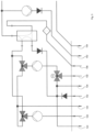
- Fig. 1 shows schematically and by way of example the hydraulics of a module 10 according to the invention in a heating system 1.
- the heating system 1 has a first heat generator 2, which is designed, for example, as a heat pump, and a second heat generator 3, which is, for example, a boiler or a thermal bath.
- the heating system 1 also has a heat storage 4, for example a hot water storage tank, in which drinking water is stored for provision, for example at fittings.
- the heating system 1 has a heat consumer 5, which in this example has a first heating circuit 6 and a second heating circuit 7 as examples of a heat consumer.
- Fig. 1 The connections or hydraulic lines that usually carry water as a fluid are referred to in common jargon as flows or returns.
- Fig. 2 shows an example of a view of the components including connections and housing.
- the first heat generator 2 which is usually designed as a heat pump WP, has, as indicated, a flow WPVL and a return WPRL.
- the flow directions of the fluid, usually water, are shown schematically by arrows. shown.
- the heat consumer 5 or the schematically shown first and second heating circuits 6, 7 have a flow HKVL or HK2VL and a return HKRL or HK2RL.
- the second heating circuit 7 is optional and the heating system 1 can also be used with only one heating circuit, for example the heating circuit 6 as a heat consumer 5.
- the module 10 has a hydraulic arrangement 100 that enables the connections and hydraulics of the system.
- the heat pump flow WPVL is integrated via a first switching valve 110, with which it is possible to switch between heating operation and hot water operation.
- the heat generated can be introduced into the heat consumer 5 via a hydraulic switch 120.
- the hydraulic switch 120 decouples the first heat generator 2 or the second heat generator 3 from the heat consumer 5 and therefore protects the heat generator from a completely closed circuit of the heat consumer 5.
- the hydraulic switch 120 can also be understood as a buffer storage.
- a common return of the heat storage 4, namely the hot water return WWRL, and the hydraulic switch 120 leads back to the first heat generator 2 via the heat pump return WPRL and to the second heat generator 3 via the thermal bath return ThRL.
- the second heat generator 3 is integrated into the heating system 1 via a mixing valve 130 and a second switching valve 140.
- the mixing valve 130 ensures the required target temperature of the heat consumer 5.
- the second switching valve 140 functions analogously to the first switching valve 110.
- the hydraulic switch 120 ensures a guaranteed minimum volume flow, particularly when using thermal baths as a second heat generator 3.
- a hydraulic drive 150, 160, 170 for example a pump
- the second heating circuit 7 is available as an option, with a tap of the flow HK2VL located directly behind the hydraulic switch 120 and in front of the hydraulic drive 170.
- the second heating circuit 7 is therefore independent of the operation of the hydraulic drive 170. The return of the first heating circuit 6 and the second heating circuit 7 must be brought together externally in this case.
- a controller 60 designated WPM4 is also shown.
- the controller 60 is set up to implement a control of the heating system 1 based on the efficiencies of the first heat generator 2 and the second heat generator 3.
- the controller 60 is preferably designed to implement an adaptive bivalence point control, which selects the optimal heat generator from the heat generator 2 and the heat generator 3 based on the efficiencies of the heat generators 2, 3 and the corresponding energy costs, energy efficiencies or CO2 emissions.
- the heating operation can, especially at the request of the user, be optimized economically or ecologically, or, for example, based on CO2 emissions. Alternatively or additionally, a classic operating mode can also be implemented via a bivalence point.
- the controller 60 preferably acts independently based on a comfort zone selected by the user in order to implement or regulate the set goal.
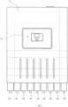
- Fig. 2 shows schematically and by way of example a perspective view of an embodiment of the module 10, which is shown schematically in Fig. 1 is shown.
- the hydraulic arrangement 100 of the module 10 including the connections of the other components of the heating system 1 can be clearly seen on the underside of a housing 12.
- the housing 12 preferably includes all of the hydraulics in an EPP housing, which is in place for better visibility Fig. 2 is not shown and ultimately serves as insulation. This eliminates the work associated with the insulation during assembly, since the module 10 is delivered prefabricated including the insulation.
- the module 10 therefore compresses the entire system structure into the housing 12, which can preferably be mounted on a wall and, in one example, has dimensions of a maximum of 950 x 770 x 300 mm and is therefore very compact and easy to assemble. Because all connections are on the underside of the housing, connecting the hydraulic system components is simplified.
- the controller 60 controls and regulates all components of the heating system 10 at a central location.
- the module 10 includes a connection 122 for connecting the heat pump flow WPVL, as well as a connection 124 for connecting the heat pump return WPRL.
- Flow direction in the hydraulic arrangement 100 indicated schematically by arrows.
- the housing 12 is closed with a cap 13.
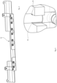
- a fastening strip 14 ( Fig. 4 ) is provided in the housing 12 for fixing pipes. Furthermore, the pipes in the housing are secured by clamping cams 15 ( Fig. 5 ) held.
- the module 10 includes a connection 132 for connecting to the flow ThVL and a connection 134 for connecting to the return ThRL.
- the module 10 includes a connection 142 for the flow WWVL and a connection 144 for the return WWRL.
- the module 10 for connecting the heat consumer 5, in particular the two heating circuits 6 and 7, includes a connection 152 for connecting to the flow of the first heating circuit HKVL, a connection 154 for connecting to the flow of the second heating circuit HK2VL and a combined return for connecting to the return of both heating circuits HKRL, connection 156.
- Fig. 3 shows schematically and as an example the in Fig. 1 Hydraulics shown in another exemplary representation.
- the controller 60 is preferably designed to communicate setpoints to the first heat generator 2 or the second heat generator 3, so that in particular the second heat generator 3 only has to be operated at an appropriate temperature, that is, at a temperature that is suitable for the heat storage 4 or the heat consumer 5 is currently needed. Without such communication, the second heat generator 3 must always provide the higher, required temperature, which is usually the temperature of the heat storage 4, which is then optionally mixed to a lower temperature using the mixing valve 130.
- the module 10 can be combined with any fossil heat generator 3, regardless of the manufacturer.
- the module 10 thus enables highly variable use when it comes to putting together the hybrid system for the heating system 1.
- the second heat generator 3 only needs to be able to be switched on or off externally. Accordingly, thanks to the invention, when renovating a heater, only the module 10 according to the invention needs to be provided and the individual components already present need to be connected to the module 10 via the connections.
- the control 60 of the module 10 then takes over the operation of the heating system 1.
- the module 10 according to the invention is particularly used when renovating an old building, it is also suitable as a permanent solution for hybrid systems or as a temporary solution if a building is to be subsequently insulated or an existing oil tank needs to be emptied.
- a permanent solution you can react flexibly to price developments from electricity, gas and oil providers.
- module 10 according to the invention enables cooling up to the condensation point.
- the operating direction of the first heat generator 2 designed as a heat pump simply needs to be reversed.
- a module 10 for integrating two heat generators 2, 3 into a heating system 1 with a hydraulic arrangement 100 is proposed, the hydraulic arrangement 100 providing hydraulic connections between connections 122, 124, 132, 134, 142, 144, 152, 154, 156 and with a controller 60, wherein the hydraulic arrangement 100 has: a first switching valve 110, a mixing valve 130 and a second switching valve 140, wherein the controller 60 is set up to regulate based on the efficiencies of the first heat generator 2 and the second heat generator 3 of the heating system 1 to be implemented.
- FIGS. 6 and 7 show a closed module 10 with the housing 12, the cap 13 and the controller 16.
Landscapes
- Engineering & Computer Science (AREA)
- Physics & Mathematics (AREA)
- Thermal Sciences (AREA)
- Chemical & Material Sciences (AREA)
- Combustion & Propulsion (AREA)
- Mechanical Engineering (AREA)
- General Engineering & Computer Science (AREA)
- Steam Or Hot-Water Central Heating Systems (AREA)
- Heat-Pump Type And Storage Water Heaters (AREA)
Claims (10)
- Module (10) destiné à l'intégration de deux générateurs de chaleur (2, 3) dans un système de chauffage (1), comprenant- des raccordements (122, 124) destinés au raccordement d'un premier générateur de chaleur (2),- des raccordements (132, 134) destinés au raccordement d'un second générateur de chaleur (3),- des raccordements (142, 144) destinés au raccordement d'un accumulateur de chaleur (4), en particulier un ballon d'eau chaude,- des raccordements (152, 154, 156) destinés au raccordement d'un consommateur de chaleur (5), en particulier un circuit de chauffage (6, 7),- un agencement hydraulique (100), l'agencement hydraulique (100) permettant d'obtenir des liaisons hydrauliques entre les raccordements (122, 124, 132, 134, 142, 144, 152, 154, 156), et- une commande (60),l'agencement hydraulique (100) présentant :- une première vanne d'inversion (110) qui est prévue dans l'agencement hydraulique (100), en aval dans un raccordement (122) d'un départ (WPVL) du premier générateur de chaleur (2), et qui est conçue pour réguler une voie d'écoulement allant du premier générateur de chaleur (2) à l'accumulateur de chaleur (4) et au consommateur de chaleur (5),- une vanne mélangeuse (130) qui est conçue pour mélanger du fluide du second générateur de chaleur (3) avec du fluide de l'accumulateur de chaleur (4) de telle manière qu'une température souhaitée se règle à la sortie de la vanne mélangeuse (130) et- une seconde vanne d'inversion (140) qui est disposée dans la voie d'écoulement en aval d'une sortie de la vanne mélangeuse (130) et qui est conçue pour réguler une voie d'écoulement allant du second générateur de chaleur (3) à l'accumulateur de chaleur (4) et au consommateur de chaleur (5),la commande (60) étant conçue pour mettre en oeuvre une régulation du système de chauffage (1) en fonction de rendements du premier générateur de chaleur (2) et du second générateur de chaleur (3).
- Module (10) selon la revendication 1, dans lequel la régulation comprend une régulation adaptative fonction du point de bivalence, les coûts énergétiques, les valeurs d'efficacité énergétique et/ou les émissions de CO2 étant pris en compte, en plus des rendements du premier générateur de chaleur (2) et du second générateur de chaleur (3), pour la sélection du générateur de chaleur entre le premier générateur de chaleur (2) et le second générateur de chaleur (4).
- Module (10) selon la revendication 1, dans lequel la régulation est conçue pour optimiser le fonctionnement du système de chauffage (1) du point de vue économique ou écologique en fonction d'une entrée utilisateur.
- Module (10) selon l'une des revendications précédentes, dans lequel l'agencement hydraulique (100) présente un séparateur hydraulique (120) destiné à découpler le premier générateur de chaleur (2) du consommateur de chaleur (5).
- Module (10) selon l'une des revendications précédentes, le module (10) présentant un boîtier (12), en particulier un boîtier (12) à montage mural, et les raccordements sont accessibles sur une face inférieure du boîtier.
- Module (10) selon la revendication 5, dans lequel le boîtier (12) présente du PPE ou en est constitué, le PPE servant d'isolant.
- Module (10) selon l'une des revendications précédentes, dans lequel le module présente respectivement un entraînement hydraulique (150, 160, 170), en particulier une pompe, pour le premier générateur de chaleur (2), pour le second générateur de chaleur (3) et/ou pour le consommateur de chaleur (5).
- Système de chauffage (1) comportant- un module (10) selon l'une des revendications précédentes,- un premier générateur de chaleur (2),- un second générateur de chaleur (3) et- un consommateur de chaleur (5).
- Système de chauffage (1) selon la revendication 8, dans lequel le consommateur de chaleur (5) est préparé pour une liaison avec deux circuits de chauffage (6, 7).
- Système de chauffage (1) selon la revendication 8 ou 9, dans lequel le premier générateur de chaleur (2) comprend une pompe à chaleur et le second générateur de chaleur (3) comprend un chauffe-eau et/ou une chaudière.
Applications Claiming Priority (1)
| Application Number | Priority Date | Filing Date | Title |
|---|---|---|---|
| DE102019001633.5A DE102019001633A1 (de) | 2019-03-08 | 2019-03-08 | Modul zur Integration von Wärmeerzeugern in Heizsystem |
Publications (2)
| Publication Number | Publication Date |
|---|---|
| EP3705786A1 EP3705786A1 (fr) | 2020-09-09 |
| EP3705786B1 true EP3705786B1 (fr) | 2023-12-20 |
Family
ID=70227966
Family Applications (1)
| Application Number | Title | Priority Date | Filing Date |
|---|---|---|---|
| EP20401015.1A Active EP3705786B1 (fr) | 2019-03-08 | 2020-03-06 | Module d'intégration des générateurs de chaleur dans un système de chauffage |
Country Status (2)
| Country | Link |
|---|---|
| EP (1) | EP3705786B1 (fr) |
| DE (1) | DE102019001633A1 (fr) |
Cited By (2)
| Publication number | Priority date | Publication date | Assignee | Title |
|---|---|---|---|---|
| EP4636321A1 (fr) * | 2024-04-17 | 2025-10-22 | Castra Groep B.V. | Ensemble de raccordement pour un système de régulation de chaleur |
| EP4686881A1 (fr) | 2024-08-01 | 2026-02-04 | Giordano Controls S.p.A. | Station de pompage pour systemes de chauffage ou de refroidissement hybrides, systeme de chauffage ou de refroidissement hybride et procede de gestion de systemes de chauffage et/ou de refroidissement hybrides |
Families Citing this family (11)
| Publication number | Priority date | Publication date | Assignee | Title |
|---|---|---|---|---|
| DE102020214909A1 (de) | 2020-11-27 | 2022-06-02 | Robert Bosch Gesellschaft mit beschränkter Haftung | Verfahren zum Betrieb eines bivalenten Heizsystems, Steuergerät und bivalentes Heizsystem |
| DE102022212632A1 (de) * | 2022-11-25 | 2024-05-29 | Robert Bosch Gesellschaft mit beschränkter Haftung | Hydraulikeinheit für eine Heizungsinstallation |
| DE102023103643A1 (de) * | 2023-02-15 | 2024-08-22 | Vaillant Gmbh | Vorrichtung für ein Heizsystem sowie Heizsystem und Verfahren zu dessen Betrieb |
| DE102023105835A1 (de) * | 2023-03-09 | 2024-09-12 | Vaillant Gmbh | Verfahren zur Umrüstung einer Heizungsanlage, Heizungsanlage und Verwendung |
| EP4677272A1 (fr) | 2023-03-10 | 2026-01-14 | BDR Thermea Group B.V. | Kit de cadre de couplage de pompe à chaleur doté d'une fente de réception |
| EP4677280A1 (fr) | 2023-03-10 | 2026-01-14 | BDR Thermea Group B.V. | Kit de cadre de pompe à chaleur hybride doté d'une fente de réception |
| WO2024240331A1 (fr) * | 2023-05-22 | 2024-11-28 | Bdr Thermea Group B.V. | Kit de cadre de couplage de pompe à chaleur doté d'un ensemble de connecteurs alignés |
| FR3146509B3 (fr) * | 2023-03-10 | 2025-04-18 | Beaulande Cedric | Module préfabriqué pour le couplage d’un module de chauffe à un réseau de chauffage central |
| DE102023117103A1 (de) * | 2023-06-28 | 2025-01-02 | Peter Brecklinghaus | Heizkreis-Hydraulikmodul für ein Zentralheizungssystem, Abzweigs-Strömungskreis-Hydraulikmodul für ein Zentralheizungssystem, Universal-Gehäuse für in Zentralheizungssysteme einsetzbare Hydraulikmodule und zugehöriges Zentralheizungssystem |
| DE102023117101A1 (de) * | 2023-06-28 | 2025-01-02 | Peter Brecklinghaus | Zentralheizungssystem und Verfahren zum Betrieb und/oder zur Steuerung und/oder zur Regelung eines Zentralheizungssystems |
| NL2035999B1 (nl) | 2023-10-10 | 2025-04-28 | Dtks Holding B V | Verwarmingssysteem en overgangstoestel |
Family Cites Families (7)
| Publication number | Priority date | Publication date | Assignee | Title |
|---|---|---|---|---|
| DE2613967A1 (de) * | 1976-04-01 | 1977-10-13 | Bosch Gmbh Robert | Installations-element |
| DE20103062U1 (de) * | 2001-02-21 | 2002-07-04 | Alfons Renn GmbH, 87474 Buchenberg | Verteilerstation für eine Heizungs- und Wasserversorgungsanlage |
| DE20301965U1 (de) * | 2003-02-07 | 2003-05-22 | SOLON Thermie GmbH, 33100 Paderborn | Steuervorrichtung für eine Solaranlage |
| EP2246633A3 (fr) * | 2009-04-30 | 2014-03-26 | Vaillant GmbH | Installation thermique solaire dotée d'une pompe à chaleur et procédé de fonctionnement d'une telle installation |
| JP6029579B2 (ja) * | 2010-05-05 | 2016-11-24 | グリーンスリーブス、エルエルシー | 複数の異なる熱エネルギー源及び熱シンクの最適使用を決定するための方法 |
| DE102012024586A1 (de) * | 2012-12-17 | 2014-06-18 | Meibes System-Technik Gmbh | Mehrkreisige Heizungs- oder Kühlanlage mit Mehrwegemischventil und Einrichtung zum Steuern und/oder Regeln für eine mehrkreisige Heizungs- oder Kühlanlage |
| EP3218652A1 (fr) * | 2014-11-12 | 2017-09-20 | Rea, David Patrick | Collecteur, bac tampon comprenant le collecteur et procédé pour faire fonctionner un système d'échange de chaleur |
-
2019
- 2019-03-08 DE DE102019001633.5A patent/DE102019001633A1/de not_active Withdrawn
-
2020
- 2020-03-06 EP EP20401015.1A patent/EP3705786B1/fr active Active
Cited By (3)
| Publication number | Priority date | Publication date | Assignee | Title |
|---|---|---|---|---|
| EP4636321A1 (fr) * | 2024-04-17 | 2025-10-22 | Castra Groep B.V. | Ensemble de raccordement pour un système de régulation de chaleur |
| NL2037481B1 (en) * | 2024-04-17 | 2025-11-03 | Castra Groep B V | Connecting assembly for a heat control system |
| EP4686881A1 (fr) | 2024-08-01 | 2026-02-04 | Giordano Controls S.p.A. | Station de pompage pour systemes de chauffage ou de refroidissement hybrides, systeme de chauffage ou de refroidissement hybride et procede de gestion de systemes de chauffage et/ou de refroidissement hybrides |
Also Published As
| Publication number | Publication date |
|---|---|
| EP3705786A1 (fr) | 2020-09-09 |
| DE102019001633A1 (de) | 2020-09-10 |
Similar Documents
| Publication | Publication Date | Title |
|---|---|---|
| EP3705786B1 (fr) | Module d'intégration des générateurs de chaleur dans un système de chauffage | |
| DE2747813B2 (de) | Anlage zur Raumheizung und Brauchwasserbereitung | |
| DE102022127741A1 (de) | Nachrüstsatz für ein bereits vorhandenes Zentralheizungssystem und ein Verfahren zum Nachrüsten eines bereits vorhandenen Zentralheizungssystems mittels eines Nachrüstsatzes | |
| DE102010023777A1 (de) | Heizungsanlage und Verfahren zum Betreiben der Heizungsanlage | |
| AT508737A2 (de) | Vorrichtung zur wärmeregelung | |
| DE202007008024U1 (de) | Mischeinrichtung zur Einstellung der Warmwassertemperatur | |
| EP2287547A1 (fr) | Pompe à chaleur et procédé de réglage de la température d'entrée de sources sur une pompe à chaleur | |
| DE102021211129A1 (de) | Hybridheizsystem zum Bereitstellen von Brauchwasser und Heizungswärme | |
| EP3385624B1 (fr) | Procédé de fonctionnement d'une installation de préparation d'eau sanitaire ou de chauffage, et installation de préparation d'eau sanitaire | |
| DE102016205114A1 (de) | Beheizte hydraulische Weiche zur optimierten Einbindung von Fremdwärme | |
| DE102008023254A1 (de) | Kompakt-Heizzentrale | |
| EP2821713A2 (fr) | Procédé destiné à alimenter en eau d'alimentation une installation de chauffage et installation de chauffage | |
| DE102018105965A1 (de) | Heizgerät | |
| DE10111072B4 (de) | Anlage zur Erzeugung von Strom und Wärme | |
| DE102004029376B4 (de) | Verfahren zum Betreiben eines Heizgerätes mit elektrischer Zusatzheizung | |
| DE10326263A1 (de) | Schalt- und/oder Verteilungseinheit für Fluide und Verfahren zur Programmierung bzw. zum Betrieb einer hydraulischen oder pneumatischen Anlage | |
| EP1845313A1 (fr) | Appareil à accumulation de chaleur | |
| DE10102022A1 (de) | Wasserheizanlage | |
| DE102022127744B4 (de) | Zentralheizungssystem und Verfahren zum Betrieb und/oder zur Steuerung und/oder zur Regelung eines Zentralheizungssystems | |
| EP2522917B1 (fr) | Procédé de fonctionnement d'une installation de chauffage | |
| DE102023117101A1 (de) | Zentralheizungssystem und Verfahren zum Betrieb und/oder zur Steuerung und/oder zur Regelung eines Zentralheizungssystems | |
| DE102014007598A1 (de) | Verfahren und Anordnung zur Reduzierung von Rücklauftemperaturniveaus in Heizungsanlagen mit beliebig vielen Heizkreisen | |
| DE19910829B4 (de) | Mehrkreiswärmetauscher | |
| DE202024101950U1 (de) | Hydraulikmodul für ein Zentralheizungssystem bzw. Zentralheizungssystem mit dem zuvor genannten Hydraulikmodul | |
| DE102023117103A1 (de) | Heizkreis-Hydraulikmodul für ein Zentralheizungssystem, Abzweigs-Strömungskreis-Hydraulikmodul für ein Zentralheizungssystem, Universal-Gehäuse für in Zentralheizungssysteme einsetzbare Hydraulikmodule und zugehöriges Zentralheizungssystem |
Legal Events
| Date | Code | Title | Description |
|---|---|---|---|
| PUAI | Public reference made under article 153(3) epc to a published international application that has entered the european phase |
Free format text: ORIGINAL CODE: 0009012 |
|
| STAA | Information on the status of an ep patent application or granted ep patent |
Free format text: STATUS: THE APPLICATION HAS BEEN PUBLISHED |
|
| AK | Designated contracting states |
Kind code of ref document: A1 Designated state(s): AL AT BE BG CH CY CZ DE DK EE ES FI FR GB GR HR HU IE IS IT LI LT LU LV MC MK MT NL NO PL PT RO RS SE SI SK SM TR |
|
| AX | Request for extension of the european patent |
Extension state: BA ME |
|
| STAA | Information on the status of an ep patent application or granted ep patent |
Free format text: STATUS: REQUEST FOR EXAMINATION WAS MADE |
|
| 17P | Request for examination filed |
Effective date: 20210309 |
|
| RBV | Designated contracting states (corrected) |
Designated state(s): AL AT BE BG CH CY CZ DE DK EE ES FI FR GB GR HR HU IE IS IT LI LT LU LV MC MK MT NL NO PL PT RO RS SE SI SK SM TR |
|
| P01 | Opt-out of the competence of the unified patent court (upc) registered |
Effective date: 20230524 |
|
| GRAP | Despatch of communication of intention to grant a patent |
Free format text: ORIGINAL CODE: EPIDOSNIGR1 |
|
| STAA | Information on the status of an ep patent application or granted ep patent |
Free format text: STATUS: GRANT OF PATENT IS INTENDED |
|
| INTG | Intention to grant announced |
Effective date: 20230718 |
|
| GRAS | Grant fee paid |
Free format text: ORIGINAL CODE: EPIDOSNIGR3 |
|
| GRAA | (expected) grant |
Free format text: ORIGINAL CODE: 0009210 |
|
| STAA | Information on the status of an ep patent application or granted ep patent |
Free format text: STATUS: THE PATENT HAS BEEN GRANTED |
|
| AK | Designated contracting states |
Kind code of ref document: B1 Designated state(s): AL AT BE BG CH CY CZ DE DK EE ES FI FR GB GR HR HU IE IS IT LI LT LU LV MC MK MT NL NO PL PT RO RS SE SI SK SM TR |
|
| REG | Reference to a national code |
Ref country code: GB Ref legal event code: FG4D Free format text: NOT ENGLISH |
|
| REG | Reference to a national code |
Ref country code: DE Ref legal event code: R096 Ref document number: 502020006436 Country of ref document: DE |
|
| REG | Reference to a national code |
Ref country code: CH Ref legal event code: EP |
|
| REG | Reference to a national code |
Ref country code: IE Ref legal event code: FG4D Free format text: LANGUAGE OF EP DOCUMENT: GERMAN |
|
| PG25 | Lapsed in a contracting state [announced via postgrant information from national office to epo] |
Ref country code: GR Free format text: LAPSE BECAUSE OF FAILURE TO SUBMIT A TRANSLATION OF THE DESCRIPTION OR TO PAY THE FEE WITHIN THE PRESCRIBED TIME-LIMIT Effective date: 20240321 |
|
| REG | Reference to a national code |
Ref country code: LT Ref legal event code: MG9D |
|
| PG25 | Lapsed in a contracting state [announced via postgrant information from national office to epo] |
Ref country code: LT Free format text: LAPSE BECAUSE OF FAILURE TO SUBMIT A TRANSLATION OF THE DESCRIPTION OR TO PAY THE FEE WITHIN THE PRESCRIBED TIME-LIMIT Effective date: 20231220 |
|
| REG | Reference to a national code |
Ref country code: NL Ref legal event code: MP Effective date: 20231220 |
|
| PG25 | Lapsed in a contracting state [announced via postgrant information from national office to epo] |
Ref country code: ES Free format text: LAPSE BECAUSE OF FAILURE TO SUBMIT A TRANSLATION OF THE DESCRIPTION OR TO PAY THE FEE WITHIN THE PRESCRIBED TIME-LIMIT Effective date: 20231220 |
|
| PG25 | Lapsed in a contracting state [announced via postgrant information from national office to epo] |
Ref country code: LT Free format text: LAPSE BECAUSE OF FAILURE TO SUBMIT A TRANSLATION OF THE DESCRIPTION OR TO PAY THE FEE WITHIN THE PRESCRIBED TIME-LIMIT Effective date: 20231220 Ref country code: GR Free format text: LAPSE BECAUSE OF FAILURE TO SUBMIT A TRANSLATION OF THE DESCRIPTION OR TO PAY THE FEE WITHIN THE PRESCRIBED TIME-LIMIT Effective date: 20240321 Ref country code: FI Free format text: LAPSE BECAUSE OF FAILURE TO SUBMIT A TRANSLATION OF THE DESCRIPTION OR TO PAY THE FEE WITHIN THE PRESCRIBED TIME-LIMIT Effective date: 20231220 Ref country code: ES Free format text: LAPSE BECAUSE OF FAILURE TO SUBMIT A TRANSLATION OF THE DESCRIPTION OR TO PAY THE FEE WITHIN THE PRESCRIBED TIME-LIMIT Effective date: 20231220 Ref country code: BG Free format text: LAPSE BECAUSE OF FAILURE TO SUBMIT A TRANSLATION OF THE DESCRIPTION OR TO PAY THE FEE WITHIN THE PRESCRIBED TIME-LIMIT Effective date: 20240320 |
|
| PG25 | Lapsed in a contracting state [announced via postgrant information from national office to epo] |
Ref country code: NL Free format text: LAPSE BECAUSE OF FAILURE TO SUBMIT A TRANSLATION OF THE DESCRIPTION OR TO PAY THE FEE WITHIN THE PRESCRIBED TIME-LIMIT Effective date: 20231220 |
|
| PG25 | Lapsed in a contracting state [announced via postgrant information from national office to epo] |
Ref country code: SE Free format text: LAPSE BECAUSE OF FAILURE TO SUBMIT A TRANSLATION OF THE DESCRIPTION OR TO PAY THE FEE WITHIN THE PRESCRIBED TIME-LIMIT Effective date: 20231220 Ref country code: RS Free format text: LAPSE BECAUSE OF FAILURE TO SUBMIT A TRANSLATION OF THE DESCRIPTION OR TO PAY THE FEE WITHIN THE PRESCRIBED TIME-LIMIT Effective date: 20231220 Ref country code: NO Free format text: LAPSE BECAUSE OF FAILURE TO SUBMIT A TRANSLATION OF THE DESCRIPTION OR TO PAY THE FEE WITHIN THE PRESCRIBED TIME-LIMIT Effective date: 20240320 Ref country code: NL Free format text: LAPSE BECAUSE OF FAILURE TO SUBMIT A TRANSLATION OF THE DESCRIPTION OR TO PAY THE FEE WITHIN THE PRESCRIBED TIME-LIMIT Effective date: 20231220 Ref country code: LV Free format text: LAPSE BECAUSE OF FAILURE TO SUBMIT A TRANSLATION OF THE DESCRIPTION OR TO PAY THE FEE WITHIN THE PRESCRIBED TIME-LIMIT Effective date: 20231220 Ref country code: HR Free format text: LAPSE BECAUSE OF FAILURE TO SUBMIT A TRANSLATION OF THE DESCRIPTION OR TO PAY THE FEE WITHIN THE PRESCRIBED TIME-LIMIT Effective date: 20231220 |
|
| PG25 | Lapsed in a contracting state [announced via postgrant information from national office to epo] |
Ref country code: IS Free format text: LAPSE BECAUSE OF FAILURE TO SUBMIT A TRANSLATION OF THE DESCRIPTION OR TO PAY THE FEE WITHIN THE PRESCRIBED TIME-LIMIT Effective date: 20240420 |
|
| PG25 | Lapsed in a contracting state [announced via postgrant information from national office to epo] |
Ref country code: CZ Free format text: LAPSE BECAUSE OF FAILURE TO SUBMIT A TRANSLATION OF THE DESCRIPTION OR TO PAY THE FEE WITHIN THE PRESCRIBED TIME-LIMIT Effective date: 20231220 |
|
| PG25 | Lapsed in a contracting state [announced via postgrant information from national office to epo] |
Ref country code: SK Free format text: LAPSE BECAUSE OF FAILURE TO SUBMIT A TRANSLATION OF THE DESCRIPTION OR TO PAY THE FEE WITHIN THE PRESCRIBED TIME-LIMIT Effective date: 20231220 |
|
| PG25 | Lapsed in a contracting state [announced via postgrant information from national office to epo] |
Ref country code: SM Free format text: LAPSE BECAUSE OF FAILURE TO SUBMIT A TRANSLATION OF THE DESCRIPTION OR TO PAY THE FEE WITHIN THE PRESCRIBED TIME-LIMIT Effective date: 20231220 Ref country code: SK Free format text: LAPSE BECAUSE OF FAILURE TO SUBMIT A TRANSLATION OF THE DESCRIPTION OR TO PAY THE FEE WITHIN THE PRESCRIBED TIME-LIMIT Effective date: 20231220 Ref country code: RO Free format text: LAPSE BECAUSE OF FAILURE TO SUBMIT A TRANSLATION OF THE DESCRIPTION OR TO PAY THE FEE WITHIN THE PRESCRIBED TIME-LIMIT Effective date: 20231220 Ref country code: IT Free format text: LAPSE BECAUSE OF FAILURE TO SUBMIT A TRANSLATION OF THE DESCRIPTION OR TO PAY THE FEE WITHIN THE PRESCRIBED TIME-LIMIT Effective date: 20231220 Ref country code: IS Free format text: LAPSE BECAUSE OF FAILURE TO SUBMIT A TRANSLATION OF THE DESCRIPTION OR TO PAY THE FEE WITHIN THE PRESCRIBED TIME-LIMIT Effective date: 20240420 Ref country code: EE Free format text: LAPSE BECAUSE OF FAILURE TO SUBMIT A TRANSLATION OF THE DESCRIPTION OR TO PAY THE FEE WITHIN THE PRESCRIBED TIME-LIMIT Effective date: 20231220 Ref country code: CZ Free format text: LAPSE BECAUSE OF FAILURE TO SUBMIT A TRANSLATION OF THE DESCRIPTION OR TO PAY THE FEE WITHIN THE PRESCRIBED TIME-LIMIT Effective date: 20231220 |
|
| PG25 | Lapsed in a contracting state [announced via postgrant information from national office to epo] |
Ref country code: PT Free format text: LAPSE BECAUSE OF FAILURE TO SUBMIT A TRANSLATION OF THE DESCRIPTION OR TO PAY THE FEE WITHIN THE PRESCRIBED TIME-LIMIT Effective date: 20240422 Ref country code: PL Free format text: LAPSE BECAUSE OF FAILURE TO SUBMIT A TRANSLATION OF THE DESCRIPTION OR TO PAY THE FEE WITHIN THE PRESCRIBED TIME-LIMIT Effective date: 20231220 |
|
| PG25 | Lapsed in a contracting state [announced via postgrant information from national office to epo] |
Ref country code: PT Free format text: LAPSE BECAUSE OF FAILURE TO SUBMIT A TRANSLATION OF THE DESCRIPTION OR TO PAY THE FEE WITHIN THE PRESCRIBED TIME-LIMIT Effective date: 20240422 Ref country code: PL Free format text: LAPSE BECAUSE OF FAILURE TO SUBMIT A TRANSLATION OF THE DESCRIPTION OR TO PAY THE FEE WITHIN THE PRESCRIBED TIME-LIMIT Effective date: 20231220 |
|
| REG | Reference to a national code |
Ref country code: DE Ref legal event code: R097 Ref document number: 502020006436 Country of ref document: DE |
|
| PG25 | Lapsed in a contracting state [announced via postgrant information from national office to epo] |
Ref country code: DK Free format text: LAPSE BECAUSE OF FAILURE TO SUBMIT A TRANSLATION OF THE DESCRIPTION OR TO PAY THE FEE WITHIN THE PRESCRIBED TIME-LIMIT Effective date: 20231220 |
|
| PLBE | No opposition filed within time limit |
Free format text: ORIGINAL CODE: 0009261 |
|
| STAA | Information on the status of an ep patent application or granted ep patent |
Free format text: STATUS: NO OPPOSITION FILED WITHIN TIME LIMIT |
|
| PG25 | Lapsed in a contracting state [announced via postgrant information from national office to epo] |
Ref country code: SI Free format text: LAPSE BECAUSE OF FAILURE TO SUBMIT A TRANSLATION OF THE DESCRIPTION OR TO PAY THE FEE WITHIN THE PRESCRIBED TIME-LIMIT Effective date: 20231220 |
|
| PG25 | Lapsed in a contracting state [announced via postgrant information from national office to epo] |
Ref country code: SI Free format text: LAPSE BECAUSE OF FAILURE TO SUBMIT A TRANSLATION OF THE DESCRIPTION OR TO PAY THE FEE WITHIN THE PRESCRIBED TIME-LIMIT Effective date: 20231220 Ref country code: DK Free format text: LAPSE BECAUSE OF FAILURE TO SUBMIT A TRANSLATION OF THE DESCRIPTION OR TO PAY THE FEE WITHIN THE PRESCRIBED TIME-LIMIT Effective date: 20231220 |
|
| PG25 | Lapsed in a contracting state [announced via postgrant information from national office to epo] |
Ref country code: LU Free format text: LAPSE BECAUSE OF NON-PAYMENT OF DUE FEES Effective date: 20240306 |
|
| PG25 | Lapsed in a contracting state [announced via postgrant information from national office to epo] |
Ref country code: MC Free format text: LAPSE BECAUSE OF FAILURE TO SUBMIT A TRANSLATION OF THE DESCRIPTION OR TO PAY THE FEE WITHIN THE PRESCRIBED TIME-LIMIT Effective date: 20231220 |
|
| 26N | No opposition filed |
Effective date: 20240923 |
|
| GBPC | Gb: european patent ceased through non-payment of renewal fee |
Effective date: 20240320 |
|
| PG25 | Lapsed in a contracting state [announced via postgrant information from national office to epo] |
Ref country code: MC Free format text: LAPSE BECAUSE OF FAILURE TO SUBMIT A TRANSLATION OF THE DESCRIPTION OR TO PAY THE FEE WITHIN THE PRESCRIBED TIME-LIMIT Effective date: 20231220 Ref country code: LU Free format text: LAPSE BECAUSE OF NON-PAYMENT OF DUE FEES Effective date: 20240306 |
|
| REG | Reference to a national code |
Ref country code: BE Ref legal event code: MM Effective date: 20240331 |
|
| PG25 | Lapsed in a contracting state [announced via postgrant information from national office to epo] |
Ref country code: BE Free format text: LAPSE BECAUSE OF NON-PAYMENT OF DUE FEES Effective date: 20240331 |
|
| PG25 | Lapsed in a contracting state [announced via postgrant information from national office to epo] |
Ref country code: GB Free format text: LAPSE BECAUSE OF NON-PAYMENT OF DUE FEES Effective date: 20240320 |
|
| PG25 | Lapsed in a contracting state [announced via postgrant information from national office to epo] |
Ref country code: FR Free format text: LAPSE BECAUSE OF NON-PAYMENT OF DUE FEES Effective date: 20240331 |
|
| PG25 | Lapsed in a contracting state [announced via postgrant information from national office to epo] |
Ref country code: IE Free format text: LAPSE BECAUSE OF NON-PAYMENT OF DUE FEES Effective date: 20240306 |
|
| PG25 | Lapsed in a contracting state [announced via postgrant information from national office to epo] |
Ref country code: IE Free format text: LAPSE BECAUSE OF NON-PAYMENT OF DUE FEES Effective date: 20240306 Ref country code: GB Free format text: LAPSE BECAUSE OF NON-PAYMENT OF DUE FEES Effective date: 20240320 Ref country code: FR Free format text: LAPSE BECAUSE OF NON-PAYMENT OF DUE FEES Effective date: 20240331 Ref country code: BE Free format text: LAPSE BECAUSE OF NON-PAYMENT OF DUE FEES Effective date: 20240331 |
|
| PGFP | Annual fee paid to national office [announced via postgrant information from national office to epo] |
Ref country code: CH Payment date: 20250401 Year of fee payment: 6 |
|
| PG25 | Lapsed in a contracting state [announced via postgrant information from national office to epo] |
Ref country code: CY Free format text: LAPSE BECAUSE OF FAILURE TO SUBMIT A TRANSLATION OF THE DESCRIPTION OR TO PAY THE FEE WITHIN THE PRESCRIBED TIME-LIMIT; INVALID AB INITIO Effective date: 20200306 |
|
| PG25 | Lapsed in a contracting state [announced via postgrant information from national office to epo] |
Ref country code: HU Free format text: LAPSE BECAUSE OF FAILURE TO SUBMIT A TRANSLATION OF THE DESCRIPTION OR TO PAY THE FEE WITHIN THE PRESCRIBED TIME-LIMIT; INVALID AB INITIO Effective date: 20200306 |
|
| PG25 | Lapsed in a contracting state [announced via postgrant information from national office to epo] |
Ref country code: TR Free format text: LAPSE BECAUSE OF FAILURE TO SUBMIT A TRANSLATION OF THE DESCRIPTION OR TO PAY THE FEE WITHIN THE PRESCRIBED TIME-LIMIT Effective date: 20231220 |
|
| REG | Reference to a national code |
Ref country code: CH Ref legal event code: U11 Free format text: ST27 STATUS EVENT CODE: U-0-0-U10-U11 (AS PROVIDED BY THE NATIONAL OFFICE) Effective date: 20260401 |
|
| PGFP | Annual fee paid to national office [announced via postgrant information from national office to epo] |
Ref country code: DE Payment date: 20260319 Year of fee payment: 7 |
|
| PGFP | Annual fee paid to national office [announced via postgrant information from national office to epo] |
Ref country code: AT Payment date: 20260320 Year of fee payment: 7 |