EP3706143A1 - Électrolyte solide, électrode, élément de stockage d'électricité et procédé de production d'électrolyte solide - Google Patents
Électrolyte solide, électrode, élément de stockage d'électricité et procédé de production d'électrolyte solide Download PDFInfo
- Publication number
- EP3706143A1 EP3706143A1 EP18872697.0A EP18872697A EP3706143A1 EP 3706143 A1 EP3706143 A1 EP 3706143A1 EP 18872697 A EP18872697 A EP 18872697A EP 3706143 A1 EP3706143 A1 EP 3706143A1
- Authority
- EP
- European Patent Office
- Prior art keywords
- solid electrolyte
- electrode
- tfsi
- electrolyte
- emi
- Prior art date
- Legal status (The legal status is an assumption and is not a legal conclusion. Google has not performed a legal analysis and makes no representation as to the accuracy of the status listed.)
- Granted
Links
Images







Classifications
-
- H—ELECTRICITY
- H01—ELECTRIC ELEMENTS
- H01B—CABLES; CONDUCTORS; INSULATORS; SELECTION OF MATERIALS FOR THEIR CONDUCTIVE, INSULATING OR DIELECTRIC PROPERTIES
- H01B1/00—Conductors or conductive bodies characterised by the conductive materials; Selection of materials as conductors
- H01B1/06—Conductors or conductive bodies characterised by the conductive materials; Selection of materials as conductors mainly consisting of other non-metallic substances
-
- H—ELECTRICITY
- H01—ELECTRIC ELEMENTS
- H01M—PROCESSES OR MEANS, e.g. BATTERIES, FOR THE DIRECT CONVERSION OF CHEMICAL ENERGY INTO ELECTRICAL ENERGY
- H01M10/00—Secondary cells; Manufacture thereof
- H01M10/05—Accumulators with non-aqueous electrolyte
- H01M10/056—Accumulators with non-aqueous electrolyte characterised by the materials used as electrolytes, e.g. mixed inorganic/organic electrolytes
- H01M10/0561—Accumulators with non-aqueous electrolyte characterised by the materials used as electrolytes, e.g. mixed inorganic/organic electrolytes the electrolyte being constituted of inorganic materials only
- H01M10/0562—Solid materials
-
- H—ELECTRICITY
- H01—ELECTRIC ELEMENTS
- H01B—CABLES; CONDUCTORS; INSULATORS; SELECTION OF MATERIALS FOR THEIR CONDUCTIVE, INSULATING OR DIELECTRIC PROPERTIES
- H01B1/00—Conductors or conductive bodies characterised by the conductive materials; Selection of materials as conductors
- H01B1/06—Conductors or conductive bodies characterised by the conductive materials; Selection of materials as conductors mainly consisting of other non-metallic substances
- H01B1/12—Conductors or conductive bodies characterised by the conductive materials; Selection of materials as conductors mainly consisting of other non-metallic substances organic substances
-
- H—ELECTRICITY
- H01—ELECTRIC ELEMENTS
- H01B—CABLES; CONDUCTORS; INSULATORS; SELECTION OF MATERIALS FOR THEIR CONDUCTIVE, INSULATING OR DIELECTRIC PROPERTIES
- H01B1/00—Conductors or conductive bodies characterised by the conductive materials; Selection of materials as conductors
- H01B1/06—Conductors or conductive bodies characterised by the conductive materials; Selection of materials as conductors mainly consisting of other non-metallic substances
- H01B1/12—Conductors or conductive bodies characterised by the conductive materials; Selection of materials as conductors mainly consisting of other non-metallic substances organic substances
- H01B1/124—Intrinsically conductive polymers
- H01B1/127—Intrinsically conductive polymers comprising five-membered aromatic rings in the main chain, e.g. polypyrroles, polythiophenes
-
- H—ELECTRICITY
- H01—ELECTRIC ELEMENTS
- H01M—PROCESSES OR MEANS, e.g. BATTERIES, FOR THE DIRECT CONVERSION OF CHEMICAL ENERGY INTO ELECTRICAL ENERGY
- H01M10/00—Secondary cells; Manufacture thereof
- H01M10/05—Accumulators with non-aqueous electrolyte
- H01M10/052—Li-accumulators
-
- H—ELECTRICITY
- H01—ELECTRIC ELEMENTS
- H01M—PROCESSES OR MEANS, e.g. BATTERIES, FOR THE DIRECT CONVERSION OF CHEMICAL ENERGY INTO ELECTRICAL ENERGY
- H01M10/00—Secondary cells; Manufacture thereof
- H01M10/05—Accumulators with non-aqueous electrolyte
- H01M10/056—Accumulators with non-aqueous electrolyte characterised by the materials used as electrolytes, e.g. mixed inorganic/organic electrolytes
- H01M10/0564—Accumulators with non-aqueous electrolyte characterised by the materials used as electrolytes, e.g. mixed inorganic/organic electrolytes the electrolyte being constituted of organic materials only
- H01M10/0565—Polymeric materials, e.g. gel-type or solid-type
-
- H—ELECTRICITY
- H01—ELECTRIC ELEMENTS
- H01M—PROCESSES OR MEANS, e.g. BATTERIES, FOR THE DIRECT CONVERSION OF CHEMICAL ENERGY INTO ELECTRICAL ENERGY
- H01M10/00—Secondary cells; Manufacture thereof
- H01M10/05—Accumulators with non-aqueous electrolyte
- H01M10/056—Accumulators with non-aqueous electrolyte characterised by the materials used as electrolytes, e.g. mixed inorganic/organic electrolytes
- H01M10/0564—Accumulators with non-aqueous electrolyte characterised by the materials used as electrolytes, e.g. mixed inorganic/organic electrolytes the electrolyte being constituted of organic materials only
- H01M10/0566—Liquid materials
- H01M10/0568—Liquid materials characterised by the solutes
-
- H—ELECTRICITY
- H01—ELECTRIC ELEMENTS
- H01M—PROCESSES OR MEANS, e.g. BATTERIES, FOR THE DIRECT CONVERSION OF CHEMICAL ENERGY INTO ELECTRICAL ENERGY
- H01M10/00—Secondary cells; Manufacture thereof
- H01M10/05—Accumulators with non-aqueous electrolyte
- H01M10/056—Accumulators with non-aqueous electrolyte characterised by the materials used as electrolytes, e.g. mixed inorganic/organic electrolytes
- H01M10/0564—Accumulators with non-aqueous electrolyte characterised by the materials used as electrolytes, e.g. mixed inorganic/organic electrolytes the electrolyte being constituted of organic materials only
- H01M10/0566—Liquid materials
- H01M10/0569—Liquid materials characterised by the solvents
-
- H—ELECTRICITY
- H01—ELECTRIC ELEMENTS
- H01M—PROCESSES OR MEANS, e.g. BATTERIES, FOR THE DIRECT CONVERSION OF CHEMICAL ENERGY INTO ELECTRICAL ENERGY
- H01M4/00—Electrodes
- H01M4/02—Electrodes composed of, or comprising, active material
- H01M4/13—Electrodes for accumulators with non-aqueous electrolyte, e.g. for lithium-accumulators; Processes of manufacture thereof
-
- H—ELECTRICITY
- H01—ELECTRIC ELEMENTS
- H01M—PROCESSES OR MEANS, e.g. BATTERIES, FOR THE DIRECT CONVERSION OF CHEMICAL ENERGY INTO ELECTRICAL ENERGY
- H01M4/00—Electrodes
- H01M4/02—Electrodes composed of, or comprising, active material
- H01M4/62—Selection of inactive substances as ingredients for active masses, e.g. binders, fillers
-
- H—ELECTRICITY
- H01—ELECTRIC ELEMENTS
- H01M—PROCESSES OR MEANS, e.g. BATTERIES, FOR THE DIRECT CONVERSION OF CHEMICAL ENERGY INTO ELECTRICAL ENERGY
- H01M4/00—Electrodes
- H01M4/02—Electrodes composed of, or comprising, active material
- H01M4/62—Selection of inactive substances as ingredients for active masses, e.g. binders, fillers
- H01M4/621—Binders
-
- H—ELECTRICITY
- H01—ELECTRIC ELEMENTS
- H01M—PROCESSES OR MEANS, e.g. BATTERIES, FOR THE DIRECT CONVERSION OF CHEMICAL ENERGY INTO ELECTRICAL ENERGY
- H01M4/00—Electrodes
- H01M4/02—Electrodes composed of, or comprising, active material
- H01M4/62—Selection of inactive substances as ingredients for active masses, e.g. binders, fillers
- H01M4/624—Electric conductive fillers
-
- H—ELECTRICITY
- H01—ELECTRIC ELEMENTS
- H01M—PROCESSES OR MEANS, e.g. BATTERIES, FOR THE DIRECT CONVERSION OF CHEMICAL ENERGY INTO ELECTRICAL ENERGY
- H01M10/00—Secondary cells; Manufacture thereof
- H01M10/05—Accumulators with non-aqueous electrolyte
- H01M10/056—Accumulators with non-aqueous electrolyte characterised by the materials used as electrolytes, e.g. mixed inorganic/organic electrolytes
-
- H—ELECTRICITY
- H01—ELECTRIC ELEMENTS
- H01M—PROCESSES OR MEANS, e.g. BATTERIES, FOR THE DIRECT CONVERSION OF CHEMICAL ENERGY INTO ELECTRICAL ENERGY
- H01M2300/00—Electrolytes
- H01M2300/0017—Non-aqueous electrolytes
- H01M2300/0065—Solid electrolytes
- H01M2300/0068—Solid electrolytes inorganic
-
- H—ELECTRICITY
- H01—ELECTRIC ELEMENTS
- H01M—PROCESSES OR MEANS, e.g. BATTERIES, FOR THE DIRECT CONVERSION OF CHEMICAL ENERGY INTO ELECTRICAL ENERGY
- H01M2300/00—Electrolytes
- H01M2300/0085—Immobilising or gelification of electrolyte
-
- Y—GENERAL TAGGING OF NEW TECHNOLOGICAL DEVELOPMENTS; GENERAL TAGGING OF CROSS-SECTIONAL TECHNOLOGIES SPANNING OVER SEVERAL SECTIONS OF THE IPC; TECHNICAL SUBJECTS COVERED BY FORMER USPC CROSS-REFERENCE ART COLLECTIONS [XRACs] AND DIGESTS
- Y02—TECHNOLOGIES OR APPLICATIONS FOR MITIGATION OR ADAPTATION AGAINST CLIMATE CHANGE
- Y02E—REDUCTION OF GREENHOUSE GAS [GHG] EMISSIONS, RELATED TO ENERGY GENERATION, TRANSMISSION OR DISTRIBUTION
- Y02E60/00—Enabling technologies; Technologies with a potential or indirect contribution to GHG emissions mitigation
- Y02E60/10—Energy storage using batteries
Definitions
- the present disclosure relates to a solid electrolyte, electrode, power storage device, and method for producing solid electrolytes.
- All-solid-state lithium secondary batteries have recently been under development as next-generation batteries. It has been desired to improve the ionic conductivity of solid electrolytes used in power storage devices such as all-solid-state lithium secondary batteries.
- Patent Literature 1 discloses a method for producing solid electrolytes by a sol-gel process using a liquid mixture containing an ionic liquid, lithium salt, and silica precursor.
- Patent Literature 1 JP 2012-518248 A
- the present disclosure provides a new solid electrolyte with high ionic conductivity.
- the present disclosure provides a solid electrolyte including:
- the present disclosure can provide a new solid electrolyte with high ionic conductivity.
- a solid electrolyte according to a first aspect of the present disclosure includes:
- the solid electrolyte can be maintained in gel form and high ionic conductivity can be achieved.
- the lithium salt of the solid electrolyte according to the first aspect may include lithium bis(trifluoromethanesulfonyl)imide.
- Li-TFSI lithium bis(trifluoromethanesulfonyl)imide
- the electrolyte of the solid electrolyte according to the second aspect may include a first electrolyte layer having contact with the inner surfaces of the plurality of pores, the first electrolyte layer may include a first anion layer, a first cation layer, and a second anion layer, the first anion layer may include a plurality of first bis(trifluoromethanesulfonyl)imide ions adsorbed to the inner surfaces of the plurality of pores of the porous silica, the first cation layer may include a plurality of 1-ethyl-3-methylimidazolium ions ionically bonded to the plurality of first bis(trifluoromethanesulfonyl)imide ions respectively, and the second anion layer may include a plurality of second bis(trifluoromethanesulfonyl)imide ions ionically bonded to the plurality of 1-ethyl-3-methylimida
- the molar ratio of the EMI-TFSI to the porous silica may be 1.7 or more and 1.8 or less. According to the fourth aspect, a solid electrolyte with high ionic conductivity can be reliably obtained.
- the porous silica may form a single layer, and an outer boundary of the solid electrolyte may be defined by the porous silica.
- Such a configuration allows easy handling of the solid electrolyte and easy application of the solid electrolyte to, for example, a power storage device.
- An electrode according to a sixth aspect of the present disclosure includes:
- an electrode having excellent electrical characteristics can be obtained.
- the electrode according to the sixth aspect may further include at least one selected from a conductive agent and a binder.
- the conductive agent contributes to a sufficient reduction in the internal resistance of the electrode.
- the binder serves to fix particles of the electrode active material to each other. When the particles of the electrode active material are fixed to each other, occurrence of a gap due to expansion and shrinkage of the particles of the electrode active material is reduced. This reduces a decrease in the discharged capacity of a battery including the electrode.
- the electrode according to the sixth or seventh aspect may further include a conductive agent, and a plurality of first particles made of the electrode active material and a plurality of second particles made of the conductive agent may be fixed in a matrix of the solid electrolyte.
- the electrode can reliably exercise the excellent electrical characteristics attributable to the high ionic conductivity of the solid electrolyte may be reliably exhibited.
- a power storage device includes:
- a power storage device having excellent electrical characteristics can be obtained.
- a power storage device includes:
- a power storage device having excellent electrical characteristics can be obtained.
- a method for producing solid electrolytes according to an eleventh aspect of the present disclosure includes:
- the solid electrolyte of the present disclosure can be produced efficiently.
- the silicon alkoxide may include at least one selected from tetraethyl orthosilicate and a substituted tetraethyl orthosilicate. Since tetraethyl orthosilicate is unlikely to volatile in the preparation of the liquid mixture, the use of tetraethyl orthosilicate as a raw material makes it possible to precisely control the amount of silica obtained at the end.
- FIG. 1A schematically shows an example of a cross-sectional structure of a solid electrolyte 10 according to a first embodiment.
- the solid electrolyte 10 includes porous silica 11 and an electrolyte 13.
- the porous silica 11 has a plurality of pores 12 interconnected mutually.
- the plurality of pores 12 are what are called continuous pores.
- the plurality of pores 12 may include an isolated pore.
- the electrolyte 13 coats the inner surfaces of these pores 12.
- the electrolyte 13 may at least partially fill the interior of the plurality of pores 12, or may completely fill the interior of the plurality of pores 12.
- solid refers to being in solid state as a whole system at room temperature. Partial inclusion of a liquid is not excluded. Gels, for example, are “solid”.
- the porous silica 11 is, for example, mesoporous silica.
- the porous silica 11 may have a porosity in the range of 25% to 90%.
- the diameter of each pore 12 of the porous silica 11 is, for example, in the range of 2 nm to 50 nm.
- the diameters of the pores 12 may be measured, for example, by the following method.
- the solid electrolyte 10 is immersed in an organic solvent to dissolve the electrolyte 13 in the organic solvent.
- the electrolyte 13 is then removed by supercritical drying, followed by measurement of the specific surface area of the porous silica 11 by the BET method. From the result of the measurement, the porosity and the respective diameters of the pores 12 (micropore distribution) can be calculated.
- the porosity and the diameters of the pores 12 can be determined by preparing a thin piece of the solid electrolyte 10 by focused ion beam (FIB) and observing the thin piece of the solid electrolyte 10 with a transmission electron microscope (TEM).
- FIB focused ion beam
- TEM transmission electron microscope
- the porous silica 11 forms a single layer.
- the layer of the porous silica 11 may be self-supporting.
- the outer boundary of the solid electrolyte 10 is defined by the porous silica 11.
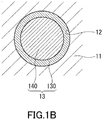
- FIG. 1B schematically shows an example of a cross-section of one of the pores 12 of the porous silica 11.
- the electrolyte 13 forms a first electrolyte layer 130 as a continuous film on the inner surfaces of the plurality of pores 12.
- ions of the electrolyte 13 are oriented regularly.
- the first electrolyte layers 130 respectively provided on the inner surfaces of the plurality of pores 12 are mutually interconnected to form a three-dimensional network.
- a conduction path through which a lithium ion moves is formed near the interface between the porous silica 11 and electrolyte 13, specifically, on the inner surface of the first electrolyte layer 130 provided along the plurality of pores 12.
- the electrolyte 13 may include a second electrolyte layer 140.
- the second electrolyte layer 140 has contact with the inner surface of the first electrolyte layer 130.
- the second electrolyte layer 140 is located in the central portion of the pore 12.
- the first electrolyte layer 130 surrounds the second electrolyte layer 140.
- the second electrolyte layer 140 is a layer in which ions derived from an ionic liquid and lithium salt are oriented irregularly.
- the electrolyte 13 includes an ionic liquid and lithium salt.
- the ionic liquid contains 1-ethyl-3-methylimidazolium bis(trifluoromethanesulfonyl)imide represented by EMI-TFSI.
- the lithium salt is dissolved in EMI-TFSI.
- lithium salt examples include lithium perchlorate (LiClO 4 ), lithium borofluoride (LiBF 4 ), lithium hexafluorophosphate (LiPF 6 ), lithium bis(fluorosulfonyl)imide (Li-FSI), lithium bis(trifluoromethanesulfonyl)imide (Li-TFSI), and lithium bis(pentafluoroethanesulfonyl)imide (Li-BETI).
- Li-FSI lithium bis(fluorosulfonyl)imide
- Li-TFSI lithium bis(trifluoromethanesulfonyl)imide
- Li-BETI lithium bis(pentafluoroethanesulfonyl)imide
- the molar ratio of EMI-TFSI to the porous silica 11 is, for example, larger than 1.5 and less than 2.0. This makes it possible to maintain the solid electrolyte 10 in gel form and achieve high ionic conductivity. If the molar ratio of EMI-TFSI to the porous silica 11 is 1.5 or less or 2.0 or more, it is difficult to achieve high ionic conductivity (for example, 2.8 mS/cm or more). If the molar ratio of EMI-TFSI to the porous silica 11 is too large, it is difficult to obtain the solid electrolyte 10 in gel form.
- the molar ratio of EMI-TFSI to the porous silica 11 may be determined, for example, by element analysis of the solid electrolyte 10. Specifically, the molar ratio of EMI-TFSI to the porous silica 11 can be calculated from the ratio between Si included in the porous silica 11 and an element (for example, N, S, or F) included in EMI-TFSI.
- the element analysis include energy dispersive X-ray (EDX) analysis, electron energy loss spectroscopy (EELS) analysis, Rutherford backscattering spectrometry (RBS) analysis, X-ray photoelectron spectroscopy (XPS) analysis, and Auger electron spectroscopy (AES) analysis.
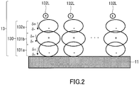
- FIG. 2 schematically shows an example of a structure of the first electrolyte layer 130 in the vicinity of the inner surface of the pore 12 of the porous silica 11.
- a bis(trifluoromethanesulfonyl)imide ion may be described herein as "TFSI - ion”.
- a 1-ethyl-3-methylimidazolium ion may be described as "EMI + ion”.
- the first electrolyte layer 130 includes a first anion layer 131a, first cation layer 131b, and second anion layer 132a.
- the first anion layer 131a, first cation layer 131b, and second anion layer 132a are arranged on the inner surface of the pore 12 in this order.
- the first anion layer 131a is composed of, for example, a plurality of TFSI - ions. These TFSI - ions adsorb to the porous silica 11.
- the first cation layer 131b is composed of, for example, a plurality of EMI + ions.
- the second anion layer 132a is composed of, for example, anions (for example, TFSI - ions) derived from the lithium salt. These anions are bonded to the plurality of EMI + ions of the first cation layer 131b, respectively.
- the anions of the first anion layer 131a and first cation layer 131b may be anions derived from the ionic liquid or may be anions derived from the lithium salt.
- the form of the anion-cation bonding is, specifically, ionic bonding.
- the lithium ion 132L can easily move over the first electrolyte layer 130 (over the second anion layer 132a) by the following mechanism.
- a ⁇ -electron cloud of the TFSI - ion has large non-locality.
- the EMI + ion has a conjugated ⁇ bond attributed to a five-membered ring.
- a ⁇ -electron cloud of the EMI + ion has large non-locality.
- oxygen of the TFSI - ion is hydrogen-bonded to hydrogen of a silanol group of the porous silica 11 to form the first anion layer 131a.
- the ⁇ -electron cloud of the TFSI - ion is drawn toward the porous silica 11 according to the surface potential of the porous silica 11. This generates polarization charges in the TFSI - ion. Specifically, in the TFSI - ion, a negative polarization charge is generated on the side closer to the porous silica 11 and a positive polarization charge is generated on the side away from the porous silica 11.
- the state in which the TFSI - ion is adsorbed to and arranged on a surface of the porous silica 11 is defined as a first state.
- the state in which the TFSI - ion and EMI + ion are alternately adsorbed to and arranged on a surface of the porous silica 11 is defined as a second state.
- the first state is more stable than the second state. Therefore, the TFSI - ion is preferentially adsorbed to and arranged on a surface of the porous silica 11.
- the EMI + ion is bonded to the first anion layer 131a to form a first cation layer 131b.
- the conjugated ⁇ -electron cloud of the EMI + ion is drawn toward the first anion layer 131a by the positive polarization charge on the surface of the first anion layer 131a.
- This generates polarization charges in the EMI + ion.
- a negative polarization charge is generated on the side closer to the first anion layer 131a and a positive polarization charge is generated on the side away from the first anion layer 131a.
- the TFSI - ion is bonded to the first cation layer 131b to form a second anion layer 132a.
- the ⁇ -electron cloud of the TFSI - ion is drawn toward the first cation layer 131b by the positive polarization charge on the surface of the first cation layer 131b.
- This generates polarization charges in the TFSI - ion. Specifically, in the TFSI - ion, a negative polarization charge is generated on the side closer to the first cation layer 131b and a positive polarization charge is generated on the side away from the first cation layer 131b.
- the positive polarization charge on the surface of the second anion layer 132a can weaken the Coulomb interaction between the TFSI - ion of the second anion layer 132a and the lithium ion 132L. This is inferred to make it easy for the lithium ion 132L to move over the second anion layer 132a.
- the structure of the electrolyte 13 can be estimated in the following manner.
- a molecular vibration mode is examined by Fourier-transform infrared (FT-IR) spectroscopic analysis or Raman analysis. This allows to estimate that the ion of the electrolyte is bonded to silica. Additionally, observation by differential scanning calorimetry (DSC) of no peak or a small peak at a change from a liquid phase to a solid phase confirms the presence of the first electrolyte layer 130 already in the solid phase.
- FT-IR Fourier-transform infrared
- Raman analysis Raman analysis
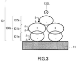
- FIG. 3 schematically shows another example of the structure of the first electrolyte layer.
- ions respectively constituting layers of a first electrolyte layer 130a are not bonded in one-to-one correspondence.
- the ions respectively constituting the layers of the first electrolyte layer 130a may be bonded to each other depending on the molar ratio between EMI-TFSI and the lithium salt.
- FIG. 4 schematically shows yet another example of the structure of the first electrolyte layer.
- a first electrolyte layer 130b includes the structure described with reference to FIG. 2 and further includes a second cation layer 132b and third anion layer 133a.
- the second cation layer 132b and third anion layer 133a are arranged in this order on the second anion layer 132a.
- the number of layers included in the first electrolyte layer is not particularly limited.
- the first electrolyte layer includes a plurality of anion layers, at least one of these anion layers includes the TFSI - ion.
- the first electrolyte layer includes a plurality of cation layers, at least one of these cation layers includes the EMI + ion.
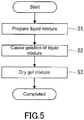
- the production method shown in FIG. 5 includes a step S1 of preparing a liquid mixture, step S2 of forming a gel mixture from the liquid mixture, and step S3 of drying the gel mixture.
- the solid electrolyte 10 described with reference to FIG. 1A can be produced efficiently by a sol-gel process.
- a silicon alkoxide, EMI-TFSI, a lithium salt, water, and an organic solvent are mixed.
- the silicon alkoxide, EMI-TFSI, the lithium salt, water, and the organic solvent are placed in a container and mixed.
- silicon alkoxide examples include tetraethyl orthosilicate (TEOS), tetramethyl orthosilicate (TMOS), and substitution products thereof.
- TEOS tetraethyl orthosilicate
- TMOS tetramethyl orthosilicate
- One silicon alkoxide or two or more silicon alkoxides selected from these silicon alkoxides can be used.
- the boiling point of TEOS is higher than the boiling point of TMOS. Since TEOS is unlikely to volatile in the preparation of the liquid mixture, the use of TEOS as a raw material makes it possible to precisely control the amount of silica obtained at the end.
- lithium salt examples include the various materials described previously.
- Water is required to hydrolyze the silicon alkoxide, and is, for example, deionized water.
- the organic solvent is required to allow the silicon alkoxide, EMI-TFSI, the lithium salt, and water to be uniformly mixed, and is, for example, an alcohol.
- the alcohol include methanol, ethanol, isopropanol, and 1-methoxy-2-propanol (PGME).
- PGME 1-methoxy-2-propanol
- the volume of the organic solvent may be, for example, 1/2 or more of and 3 times or less the sum of the volumes of the silicon alkoxide, EMI-TFSI, the lithium salt, and water. This makes it possible to mix the hydrophilic and hydrophobic materials appropriately. An increase in frequency of collision between siloxane monomers yielded from the silicon alkoxide can accelerate gelation.
- the liquid mixture may contain another material.
- a gel mixture is formed by gelation of the liquid mixture.
- the container of the liquid mixture is sealed and stored at room temperature (25°C, ambient temperature) for about 4 to 23 days, during which the liquid mixture turns into a wet gel mixture.
- the time required for the gelation can be controlled by the amount of water added, amount of the organic solvent added, and storage temperature.
- TEOS is hydrolyzed to form silanol.
- silanol undergoes dehydration polycondensation to form a siloxane monomer.
- a plurality of siloxane molecules undergo dehydration polycondensation to form a siloxane polymer.
- the siloxane polymer forms a three-dimensional network to cause gelation of the liquid mixture.
- the proportion of EMI-TFSI in the liquid mixture is too high, the formation of the siloxane network is difficult and the liquid mixture is unlikely to gelate.
- the present inventors have discovered that even when the proportion of EMI-TFSI is high, the gelation is achieved by increasing water in the liquid mixture to an amount greater than the amount of water in a conventional method.
- the gel mixture is dried.
- the solid electrolyte 10 can thus be obtained.
- the gel mixture is dried, for example, using a vacuum dryer for 48 to 72 hours under the conditions of a pressure of 0.1 to 200 Pa and a temperature of 15 to 150°C (ambient temperature).
- a pre-drying process may be carried out before the vacuum drying step to reduce occurrence of bumping and generation of air bubbles during the vacuum drying.
- the gel mixture is heated, for example, using a hot plate provided on a local exhaust system for 24 to 96 hours under the conditions of atmospheric pressure and a temperature of 15 to 90°C (surface temperature of the hot plate). Most of water and the organic solvent contained in the gel mixture can be evaporated by the pre-drying process.
- FIG. 6 schematically shows an example of a cross-sectional structure of an electrode 20 according to a second embodiment.
- the electrode 20 is disposed on a current collector 21.
- the electrode 20 includes an electrode active material, conductive agent, and solid electrolyte.
- the electrode 20 includes active material particles 22, conductive agent particles 23, and a solid electrolyte 24.
- the active material particles 22 are embedded in a matrix of the solid electrolyte 24 to be fixed.
- the conductive agent particles 23 are also embedded in the matrix of the solid electrolyte 24 to be fixed.
- the shapes of the particles 22 and 23 are not particularly limited.
- the current collector 21 is made of a conductive material.
- the conductive material include metals, conductive oxides, conductive nitrides, conductive carbides, conductive borides, and conductive resins.
- the solid electrolyte 10 described in the first embodiment can be used as the solid electrolyte 24. Since the solid electrolyte 10 of the present disclosure has high ionic conductivity, the electrode 20 having excellent electrical characteristics can be obtained by the use of the solid electrolyte 10.
- the active material particles 22 (first particles) and conductive agent particles 23 (second particles) are fixed in the matrix of the solid electrolyte 24.
- the electrode 20 can reliably exercise the excellent electrical characteristics attributable to the high ionic conductivity of the solid electrolyte 24.
- examples of the positive electrode active material include a lithium-containing transition metal oxide, vanadium oxide, chromium oxide, and lithium-containing transition metal sulfide.
- examples of the lithium-containing transition metal oxide include LiCoO 2 , LiNiO 2 , LiMnO 2 , LiMn 2 O 4 , LiNiCoMnO 2 , LiNiCoO 2 , LiCoMnO 2 , LiNiMnO 2 , LiNiCoMnO 4 , LiMnNiO 4 , LiMnCoO 4 , LiNiCoAlO 2 , LiNiPO 4 , LiCoPO 4 , LiMnPO 4 , LiFePO 4 , Li 2 NiSiO 4 , Li 2 CoSiO 4 , Li 2 MnSiO 4 , Li 2 FeSiO 4 , LiNiBO 3 , LiCoBO 3 , LiMnBO 3 , and LiFePO 4 , Li 2 NiSiO 4 , Li
- examples of the negative electrode active material include a metal, semimetal, oxide, nitride, and carbon.
- the metal and semimetal include lithium, silicon, amorphous silicon, aluminum, silver, tin, antimony, and their alloys.
- the oxide include Li 4 Ti 5 O 12 , Li 2 SrTi 6 O 14 , TiO 2 , Nb 2 O 5 , SnO 2 , Ta 2 O 5 , WO 2 , WO 3 , Fe 2 O 3 , CoO, MoO 2 , SiO, SnBPO 6 , and their mixtures.
- Examples of the nitride include LiCoN, Li 3 FeN 2 , Li 7 MnN 4 , and their mixtures.
- Examples of the carbon include graphite, graphene, hard carbon, carbon nanotube, and their mixtures.
- One negative electrode active material or two or more negative electrode active materials selected from these negative electrode active materials can be used.
- the conductive agent is, for example, a conductive carbon.
- the conductive carbon include carbon black, fibrous carbon, graphite, ketjen black, and acetylene black.
- One conductive agent or two or more conductive agents selected from these conductive agents can be used.
- the conductive agent contributes to a sufficient reduction in the internal resistance of the electrode 20.
- the electrode 20 may further include a binder.
- the binder include carboxymethyl cellulose (CMC) and styrene-butadiene rubber (SBR).
- CMC carboxymethyl cellulose
- SBR styrene-butadiene rubber
- One binder or two or more binders selected from these binders can be used.
- the binder is effective in maintaining the shape of the electrode 20.
- a liquid mixture containing the active material particles is prepared.
- the step S11 may include a sub-step S111 and sub-step S112.
- a precursor liquid is prepared by mixing, for example, EMI-TFSI, the lithium salt, water, the organic solvent, and active material particles.
- silicon alkoxide is mixed into the precursor liquid.
- a liquid mixture containing the active material particles can thus be obtained.
- silicon alkoxide is dropped into a container of the precursor liquid.
- the step S11 is the same step as the step S1 of the first embodiment, except that the active material particles are added to the liquid mixture.
- a step S12 the active material particles coated with a solid electrolyte is formed.
- the operations same as those in the step S2 and step S3 of the first embodiment are carried out. Since the liquid mixture contains the active material particles, the gelation of the liquid mixture forms a gel mixture coating at least a portion of the surface of each active material particle. The active material particles coated with the gel mixture are dried to obtain the active material particles coated with the solid electrolyte.
- a slurry containing the coated active material particles is prepared.
- the coated active material particles and conductive agent particles are added to an electrolyte solution or a solvent, which are then mixed.
- the slurry for producing the electrode can thus be obtained.
- a binder may be added to the slurry, if necessary.
- the conductive agent may be added to the liquid mixture beforehand in the step S11.
- the electrolyte solution used for the formation of the slurry include an electrolyte solution containing a lithium salt and carbonate ester.
- the carbonate ester include chain carbonates, cyclic carbonates, and their mixtures.
- the electrolyte solution can be obtained, for example, by dissolving LiPF 6 at a concentration of 1 mol/liter in a mixed solvent containing ethylene carbonate and diethyl carbonate at a volume ratio of 1:1.
- the solvent used for the preparation of the slurry include water and an organic solvent.
- the organic solvent include N-methylpyrrolidone (NMP).
- a step S14 the slurry is applied to a current collector to form a coating film.
- the method for applying the slurry is not particularly limited.
- the slurry is applied to the current collector, for example, by blade coating.
- the coating film formed on the current collector is dried.
- the dried coating film may be extended by applying pressure so as to obtain the electrode 20 having a certain volume filling rate.
- the electrode 20 can thus be obtained.
- the coating film is dried, for example, using a vacuum dryer for 4 to 12 hours under the conditions of a pressure of 0.1 to 200 Pa and a temperature of 80 to 150°C (ambient temperature).
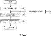
- a liquid mixture is prepared.
- the step S21 is the same step as, for example, the step S1 of the first embodiment.
- an electrode layer is formed on a current collector.
- the electrode layer can be obtained by applying a slurry containing the active material particles and conductive agent particles to the current collector and drying the resultant coating film.
- the slurry may be prepared by adding an electrolyte solution or an organic solvent to the active material particles and conductive agent particles and mixing the resultant mixture.
- the operations same as those in the step S14 and step S15 described with reference to FIG. 7 may be carried out.
- the step S21 is independent of the step S22.
- the order of the step S21 and step S22 is not particularly limited.
- the liquid mixture is impregnated into the electrode layer.
- the liquid mixture may be dropped on the electrode layer or the electrode layer may be immersed in the liquid mixture.
- the liquid mixture may partially undergo gelation before the impregnation of the electrode layer. For example, when the liquid mixture prepared is stored at room temperature for several days, the liquid mixture slightly undergoes gelation. Such a liquid mixture may be impregnated into the electrode layer.
- a step S24 the active material particles coated with a solid electrolyte is formed.
- the liquid mixture impregnated into the electrode layer undergoes gelation, and the resultant gel mixture is dried.
- the operations same as those in the step S2 and step S3 of the first embodiment are carried out.
- the electrode 20 can thus be obtained.
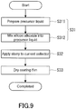
- a slurry containing the active material particles is prepared.
- the step S31 may include a sub-step S311 and sub-step S312.
- the sub-step S311 for example, EMI-TFSI, the lithium salt, water, the organic solvent, active material particles, conductive additive particles, and binder are mixed to prepare a precursor liquid.
- the silicon alkoxide is mixed in the precursor liquid.
- the slurry for producing the electrode can thus be obtained.
- the silicon alkoxide is, for example, dropped into a container of the precursor liquid.
- a step S32 the slurry is applied to a current collector to form a coating film.
- the method of applying the slurry is not particularly limited.
- the slurry is applied to the current collector, for example, by blade coating.
- a step S33 the coating film formed on the current collector is dried.
- the hydrolysis reaction and dehydration polycondensation reaction previously described progress by the drying of the coating film, resulting in formation of a matrix that is a solid electrolyte around the active material particles and conductive additive particles.
- the coating film may be stored at room temperature for a certain period of time (for example, 4 to 23 days) and subsequently dried under certain conditions.
- the coating film is dried, for example, using a vacuum dryer for 48 to 72 hours under the conditions of a pressure of 0.1 to 200 Pa and a temperature of 15 to 150°C (ambient temperature).
- the dried coating film may be extended by applying pressure so as to obtain the electrode 20 having a certain volume filling rate. The electrode 20 can thus be obtained.
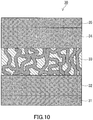
- FIG. 10 schematically shows an example of a cross-sectional structure of a power storage device 30 according to a third embodiment.
- the power storage device 30 includes a current collector 31, positive electrode 32, solid electrolyte 33, negative electrode 34, and current collector 35.
- the current collector 21 described in the second embodiment can be used as the current collectors 31 and 35.
- the positive electrode 32 includes, for example, the positive electrode active material described in the second embodiment.
- the negative electrode 34 includes, for example, the negative electrode active material described in the second embodiment.
- the solid electrolyte 33 is disposed between the positive electrode 32 and negative electrode 34.
- the solid electrolyte 10 described in the first embodiment can be used as the solid electrolyte 33. Since the solid electrolyte 10 of the present disclosure has high ionic conductivity, the power storage device 30 having excellent electrical characteristics can be obtained with the use of the solid electrolyte 10.
- FIG. 11 shows an example of a cross-sectional structure of a power storage device 40 according to a fourth embodiment.
- the power storage device 40 includes a current collector 41, positive electrode 42, solid electrolyte 43, negative electrode 44, and current collector 45.
- the current collector 21 described in the second embodiment can be used as the current collectors 41 and 45.
- the electrode 20 described in the second embodiment can be used as the positive electrode 42.
- the negative electrode 44 includes, for example, the negative electrode active material described in the second embodiment.
- the solid electrolyte 43 is disposed between the positive electrode 42 and negative electrode 44.
- the solid electrolyte 10 described in the first embodiment can be used as the solid electrolyte 43.
- the solid electrolyte 43 may be a different solid electrolyte.
- Examples of the different solid electrolyte include an inorganic solid electrolyte and polymer electrolyte.
- Examples of the inorganic solid electrolyte include an inorganic oxide and inorganic sulfide.
- Examples of the inorganic oxide include LiPON, LiAlTi(PO 4 ) 3 , LiAlGeTi(PO 4 ) 3 , LiLaTiO, LiLaZrO, Li 3 PO 4 , Li 2 SiO 2 , Li 3 SiO 4 , Li 3 VO 4 , Li 4 SiO 4 -Zn 2 SiO 4 , Li 4 GeO 4 -Li 2 GeZnO 4 , Li 2 GeZnO 4 -Zn 2 GeO 4 , and Li 4 GeO 4 -Li 3 VO 4 .
- Examples of the inorganic sulfide include Li 2 S-P 2 S 5 , Li 2 S-P 2 S 5 -LiI, Li 2 S-P 2 S 5 -Li 2 O-LiI, Li 2 S-SiS 2 , Li 2 S-SiS 2 -LiI, Li 2 S-SiS 2 -LiBr, Li 2 S-SiS 2 -LiCl, Li 2 S-SiS 2 -B 2 S 3 -LiI, Li 2 S-SiS 2 -P 2 S 5 -LiI, Li 2 S-B 2 S 3 , Li 2 S-P 2 S 5 -GeS, Li 2 S-P 2 S 5 -ZnS, Li 2 S-P 2 S 5 -GaS, Li 2 S-GeS 2 , Li 2 S-SiS 2 -Li 3 PO 4 , Li 2 S-SiS 2 -LiPO, Li 2 S-SiS 2 -Li
- the solid electrolyte 43 may be omitted when sufficient electron insulation properties can be ensured in the power storage device 40.
- a liquid mixture is applied to a surface of the electrode 20 to form a coating film.
- a thin solid electrolyte layer can be formed on the electrode 20 by gelation and drying of the coating film. When this thin layer is sufficient to prevent a short circuit between the positive electrode and negative electrode, no solid electrolyte serving as a separator is separately needed.
- the solid electrolyte-including electrode of the present disclosure is employed only as the positive electrode 42.
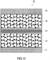
- FIG. 12 shows an example of a cross-sectional structure of a power storage device 50 according to a fifth embodiment.
- the power storage device 50 includes a current collector 51, positive electrode 52, solid electrolyte 53, negative electrode 54, and current collector 55.
- the current collector 21 described in the second embodiment can be used as the current collectors 51 and 55.
- the electrode 20 described in the second embodiment can be used as the positive electrode 52 and negative electrode 54.
- the solid electrolyte 53 is disposed between the positive electrode 52 and negative electrode 54.
- the solid electrolyte 10 described in the first embodiment can be used as the solid electrolyte 53.
- the solid electrolyte 53 may be a different solid electrolyte.
- the solid electrolyte-including electrode of the present disclosure is employed as both the positive electrode 52 and negative electrode 54.
- the solid electrolyte-including electrode of the present disclosure may be employed only as the negative electrode 54.
- the electrode 20 of the present disclosure is used as at least one selected from the positive electrode and negative electrode.
- the electrode 20 includes the solid electrolyte 10 of the present disclosure. Since the solid electrolyte 10 has high ionic conductivity, a power storage device having excellent electrical characteristics can be obtained by the use of the solid electrolyte 10.
- EMI-TFSI EMI-TFSI
- Li-TFSI 0.5 ml of TEOS
- PGME 1.5 ml
- PGME 0.5 ml
- water 0.5 ml
- the samples were sealed in the respective glass containers and stored at room temperature (25°C).
- the samples turned into wet gel mixtures in 10 to 17 days.
- FIG. 13 shows a relationship between the molar ratio of EMI-TFSI to TEOS and the ionic conductivity. Assuming that all Si atoms contained in TEOS form a skeleton of porous silica, the molar ratio of EMI-TFSI to TEOS is equal to the molar ratio of EMI-TFSI to the porous silica.
- a non-aqueous electrolyte solution containing Li-TFSI and EMI-TFSI was prepared as Reference Example.
- the molar ratio of Li-TFSI to EMI-TFSI was 0.33.
- the ionic conductivity of this non-aqueous electrolyte solution was 2.8 mS/cm.
- the ionic conductivity increases with increasing molar ratio of EMI-TFSI to TEOS.
- the molar ratio of EMI-TFSI to TEOS exceeds 1.5
- the ionic conductivity of the solid electrolyte exceeds the ionic conductivity of the non-aqueous electrolyte solution and reached about 3.0 mS/cm.
- the techniques of the present disclosure are useful for power storage devices such as lithium-ion secondary batteries.
Landscapes
- Chemical & Material Sciences (AREA)
- Chemical Kinetics & Catalysis (AREA)
- General Chemical & Material Sciences (AREA)
- Electrochemistry (AREA)
- Engineering & Computer Science (AREA)
- Physics & Mathematics (AREA)
- Manufacturing & Machinery (AREA)
- Inorganic Chemistry (AREA)
- General Physics & Mathematics (AREA)
- Condensed Matter Physics & Semiconductors (AREA)
- Materials Engineering (AREA)
- Spectroscopy & Molecular Physics (AREA)
- Dispersion Chemistry (AREA)
- Secondary Cells (AREA)
- Battery Electrode And Active Subsutance (AREA)
- Conductive Materials (AREA)
Applications Claiming Priority (2)
| Application Number | Priority Date | Filing Date | Title |
|---|---|---|---|
| JP2017212742 | 2017-11-02 | ||
| PCT/JP2018/040579 WO2019088197A1 (fr) | 2017-11-02 | 2018-10-31 | Électrolyte solide, électrode, élément de stockage d'électricité et procédé de production d'électrolyte solide |
Publications (3)
| Publication Number | Publication Date |
|---|---|
| EP3706143A1 true EP3706143A1 (fr) | 2020-09-09 |
| EP3706143A4 EP3706143A4 (fr) | 2020-11-18 |
| EP3706143B1 EP3706143B1 (fr) | 2023-11-29 |
Family
ID=66331499
Family Applications (1)
| Application Number | Title | Priority Date | Filing Date |
|---|---|---|---|
| EP18872697.0A Active EP3706143B1 (fr) | 2017-11-02 | 2018-10-31 | Électrolyte solide, électrode, élément de stockage d'électricité et procédé de production d'électrolyte solide |
Country Status (5)
| Country | Link |
|---|---|
| US (1) | US11710850B2 (fr) |
| EP (1) | EP3706143B1 (fr) |
| JP (1) | JP7177044B2 (fr) |
| ES (1) | ES2968891T3 (fr) |
| WO (1) | WO2019088197A1 (fr) |
Cited By (1)
| Publication number | Priority date | Publication date | Assignee | Title |
|---|---|---|---|---|
| EP3974562A1 (fr) * | 2020-09-28 | 2022-03-30 | Imec VZW | Procédé électrochimique de formation d'un électrolyte solide |
Families Citing this family (3)
| Publication number | Priority date | Publication date | Assignee | Title |
|---|---|---|---|---|
| US11699810B2 (en) | 2017-04-24 | 2023-07-11 | Imec Vzw | Solid nanocomposite electrolyte materials |
| WO2019088196A1 (fr) | 2017-11-02 | 2019-05-09 | アイメック・ヴェーゼットウェー | Électrolyte solide, électrode, élément de stockage d'énergie électrique, et procédé de fabrication d'électrolyte solide |
| CN116057743B (zh) * | 2020-04-07 | 2025-08-01 | 株式会社Lg新能源 | 电解质片和二次电池的制造方法 |
Family Cites Families (28)
| Publication number | Priority date | Publication date | Assignee | Title |
|---|---|---|---|---|
| US6275317B1 (en) | 1998-03-10 | 2001-08-14 | Agere Systems Optoelectronics Guardian Corp. | Hybrid integration of a wavelength selectable laser source and optical amplifier/modulator |
| JP2001228372A (ja) | 2000-02-15 | 2001-08-24 | Nec Corp | 半導体レーザモジュール |
| JP2002040350A (ja) | 2000-07-28 | 2002-02-06 | Fuji Xerox Co Ltd | 光走査装置 |
| US8119273B1 (en) | 2004-01-07 | 2012-02-21 | The United States Of America As Represented By The Department Of Energy | Unique battery with an active membrane separator having uniform physico-chemically functionalized ion channels and a method making the same |
| ES3010715T3 (en) | 2004-07-07 | 2025-04-04 | Lg Energy Solution Ltd | New organic/inorganic composite porous film and electrochemical device prepared thereby |
| JP2008060272A (ja) | 2006-08-30 | 2008-03-13 | Matsushita Electric Ind Co Ltd | 半導体レーザ装置の製造方法、および半導体レーザ装置 |
| JP4885688B2 (ja) | 2006-11-16 | 2012-02-29 | ルネサスエレクトロニクス株式会社 | 半導体レーザ装置 |
| JP2008130229A (ja) | 2006-11-16 | 2008-06-05 | National Institute Of Advanced Industrial & Technology | リチウム二次電池 |
| JP2010113939A (ja) | 2008-11-06 | 2010-05-20 | Nissan Motor Co Ltd | 双極型二次電池およびその製造方法 |
| FR2942235B1 (fr) | 2009-02-13 | 2011-07-22 | Centre Nat Rech Scient | Gels conducteurs ioniques, leur procede de preparation et leur utilisation comme electrolyte |
| JP5359440B2 (ja) | 2009-03-25 | 2013-12-04 | コニカミノルタ株式会社 | 電解質及び二次電池 |
| JP5533875B2 (ja) | 2009-08-28 | 2014-06-25 | コニカミノルタ株式会社 | 固体電解質の製造方法および二次電池 |
| JP2011113906A (ja) | 2009-11-30 | 2011-06-09 | Konica Minolta Holdings Inc | 固体電解質とその製造方法及びそれを用いた二次電池 |
| CA2841840A1 (fr) | 2011-07-11 | 2013-01-17 | Cornell University | Compositions de nanomateriau ionique de type liquide ionique (il-nim), leurs procedes et applications |
| WO2013051302A1 (fr) | 2011-10-05 | 2013-04-11 | 国立大学法人東北大学 | Batterie secondaire |
| KR101994261B1 (ko) | 2012-12-12 | 2019-06-28 | 삼성에스디아이 주식회사 | 이온성 액체를 포함하는 고체 전해질 |
| EP2814091B1 (fr) | 2013-06-11 | 2020-08-26 | IMEC vzw | Batterie à l'état solide avec un revêtement d'amélioration de diffusion d'ions en surface et son procédé de fabrication |
| WO2015015059A1 (fr) * | 2013-07-29 | 2015-02-05 | Hutchinson | Ionogel monolithique a matrice bio-polymerique, et son procede de fabrication |
| US9742028B2 (en) | 2013-08-21 | 2017-08-22 | GM Global Technology Operations LLC | Flexible membranes and coated electrodes for lithium based batteries |
| US10044062B2 (en) * | 2013-12-13 | 2018-08-07 | Tufts University | Silicone-containing ionic materials |
| JP6413675B2 (ja) | 2014-11-13 | 2018-10-31 | 住友電気工業株式会社 | 光モジュール |
| CN107408730A (zh) | 2015-02-26 | 2017-11-28 | 国立研究开发法人产业技术综合研究所 | 熔融盐组合物、电解质、及蓄电装置、以及液化熔融盐的增粘方法 |
| FR3043404B1 (fr) | 2015-11-05 | 2017-11-24 | Hutchinson | Ionogel formant un film autosupporte d'electrolyte solide, dispositif electrochimique l'incorporant et procede de fabrication de l'ionogel. |
| JP6954583B2 (ja) | 2016-01-18 | 2021-10-27 | 国立研究開発法人産業技術総合研究所 | 溶融塩を含む電解質を用いた蓄電デバイス |
| JP6814225B2 (ja) | 2016-10-20 | 2021-01-13 | 株式会社日立製作所 | リチウム二次電池 |
| JP2020024779A (ja) * | 2016-11-08 | 2020-02-13 | 株式会社日立製作所 | 二次電池用電極、二次電池、それらの製造方法 |
| JP6939771B2 (ja) | 2016-12-16 | 2021-09-22 | 住友電気工業株式会社 | 光モジュール |
| WO2019088196A1 (fr) | 2017-11-02 | 2019-05-09 | アイメック・ヴェーゼットウェー | Électrolyte solide, électrode, élément de stockage d'énergie électrique, et procédé de fabrication d'électrolyte solide |
-
2018
- 2018-10-31 WO PCT/JP2018/040579 patent/WO2019088197A1/fr not_active Ceased
- 2018-10-31 JP JP2019514841A patent/JP7177044B2/ja active Active
- 2018-10-31 US US16/481,814 patent/US11710850B2/en active Active
- 2018-10-31 ES ES18872697T patent/ES2968891T3/es active Active
- 2018-10-31 EP EP18872697.0A patent/EP3706143B1/fr active Active
Cited By (2)
| Publication number | Priority date | Publication date | Assignee | Title |
|---|---|---|---|---|
| EP3974562A1 (fr) * | 2020-09-28 | 2022-03-30 | Imec VZW | Procédé électrochimique de formation d'un électrolyte solide |
| WO2022063531A1 (fr) * | 2020-09-28 | 2022-03-31 | Imec Vzw | Procédé électrochimique pour former un électrolyte solide |
Also Published As
| Publication number | Publication date |
|---|---|
| JP7177044B2 (ja) | 2022-11-22 |
| US20190393548A1 (en) | 2019-12-26 |
| ES2968891T3 (es) | 2024-05-14 |
| JPWO2019088197A1 (ja) | 2020-09-24 |
| EP3706143A4 (fr) | 2020-11-18 |
| EP3706143B1 (fr) | 2023-11-29 |
| US11710850B2 (en) | 2023-07-25 |
| WO2019088197A1 (fr) | 2019-05-09 |
Similar Documents
| Publication | Publication Date | Title |
|---|---|---|
| US11557789B2 (en) | Solid electrolyte, electrode, power storage device, and method for producing solid electrolytes | |
| JP5472492B2 (ja) | 固体電池 | |
| JP5821857B2 (ja) | 複合活物質、複合活物質の製造方法および電池 | |
| EP3706143B1 (fr) | Électrolyte solide, électrode, élément de stockage d'électricité et procédé de production d'électrolyte solide | |
| TWI636607B (zh) | 經碳塗覆之硫化鋰 | |
| Han et al. | Monothetic and conductive network and mechanical stress releasing layer on micron‐silicon anode enabling high‐energy solid‐state battery | |
| US20230092036A1 (en) | Solid electrolyte, electrode, power storage element, and method for producing solid electrolyte | |
| JP2014530473A (ja) | 電池用活物質 | |
| Hong et al. | Deciphering enhanced solid-state kinetics of Li–S batteries via Te doping | |
| US11777143B2 (en) | Solid electrolyte, electrode, power storage device, and method for producing solid electrolytes | |
| JP6843966B2 (ja) | 半固体電解液、半固体電解質、半固体電解質層、電極、二次電池 | |
| US11081685B2 (en) | Solid electrolyte, electrode, and power storage device | |
| Das et al. | Optimizing structural and cycling stability in sodium-ion batteries using tailored glass fiber separators | |
| WO2020066058A1 (fr) | Solution électrolytique non aqueuse, électrolyte non volatil et batterie rechargeable | |
| White | Observing Conductive Properties of Ionogel Electrolytes for Solid State Batteries | |
| JP2021153010A (ja) | リチウム二次電池 |
Legal Events
| Date | Code | Title | Description |
|---|---|---|---|
| STAA | Information on the status of an ep patent application or granted ep patent |
Free format text: STATUS: THE INTERNATIONAL PUBLICATION HAS BEEN MADE |
|
| PUAI | Public reference made under article 153(3) epc to a published international application that has entered the european phase |
Free format text: ORIGINAL CODE: 0009012 |
|
| STAA | Information on the status of an ep patent application or granted ep patent |
Free format text: STATUS: REQUEST FOR EXAMINATION WAS MADE |
|
| 17P | Request for examination filed |
Effective date: 20190702 |
|
| AK | Designated contracting states |
Kind code of ref document: A1 Designated state(s): AL AT BE BG CH CY CZ DE DK EE ES FI FR GB GR HR HU IE IS IT LI LT LU LV MC MK MT NL NO PL PT RO RS SE SI SK SM TR |
|
| AX | Request for extension of the european patent |
Extension state: BA ME |
|
| A4 | Supplementary search report drawn up and despatched |
Effective date: 20201019 |
|
| RIC1 | Information provided on ipc code assigned before grant |
Ipc: H01M 4/13 20100101ALI20201013BHEP Ipc: H01M 4/62 20060101ALI20201013BHEP Ipc: H01B 1/12 20060101ALI20201013BHEP Ipc: H01M 10/052 20100101ALI20201013BHEP Ipc: H01M 10/0569 20100101ALI20201013BHEP Ipc: H01M 10/0562 20100101ALI20201013BHEP Ipc: H01B 1/06 20060101AFI20201013BHEP Ipc: H01M 10/0568 20100101ALI20201013BHEP Ipc: H01M 10/0565 20100101ALI20201013BHEP |
|
| DAV | Request for validation of the european patent (deleted) | ||
| DAX | Request for extension of the european patent (deleted) | ||
| RAP1 | Party data changed (applicant data changed or rights of an application transferred) |
Owner name: IMEC VZW |
|
| GRAP | Despatch of communication of intention to grant a patent |
Free format text: ORIGINAL CODE: EPIDOSNIGR1 |
|
| STAA | Information on the status of an ep patent application or granted ep patent |
Free format text: STATUS: GRANT OF PATENT IS INTENDED |
|
| INTG | Intention to grant announced |
Effective date: 20230904 |
|
| GRAS | Grant fee paid |
Free format text: ORIGINAL CODE: EPIDOSNIGR3 |
|
| GRAA | (expected) grant |
Free format text: ORIGINAL CODE: 0009210 |
|
| STAA | Information on the status of an ep patent application or granted ep patent |
Free format text: STATUS: THE PATENT HAS BEEN GRANTED |
|
| AK | Designated contracting states |
Kind code of ref document: B1 Designated state(s): AL AT BE BG CH CY CZ DE DK EE ES FI FR GB GR HR HU IE IS IT LI LT LU LV MC MK MT NL NO PL PT RO RS SE SI SK SM TR |
|
| REG | Reference to a national code |
Ref country code: GB Ref legal event code: FG4D |
|
| REG | Reference to a national code |
Ref country code: CH Ref legal event code: EP |
|
| P01 | Opt-out of the competence of the unified patent court (upc) registered |
Effective date: 20231031 |
|
| REG | Reference to a national code |
Ref country code: DE Ref legal event code: R096 Ref document number: 602018062003 Country of ref document: DE |
|
| REG | Reference to a national code |
Ref country code: IE Ref legal event code: FG4D |
|
| REG | Reference to a national code |
Ref country code: LT Ref legal event code: MG9D |
|
| REG | Reference to a national code |
Ref country code: NL Ref legal event code: MP Effective date: 20231129 |
|
| PG25 | Lapsed in a contracting state [announced via postgrant information from national office to epo] |
Ref country code: GR Free format text: LAPSE BECAUSE OF FAILURE TO SUBMIT A TRANSLATION OF THE DESCRIPTION OR TO PAY THE FEE WITHIN THE PRESCRIBED TIME-LIMIT Effective date: 20240301 |
|
| PG25 | Lapsed in a contracting state [announced via postgrant information from national office to epo] |
Ref country code: IS Free format text: LAPSE BECAUSE OF FAILURE TO SUBMIT A TRANSLATION OF THE DESCRIPTION OR TO PAY THE FEE WITHIN THE PRESCRIBED TIME-LIMIT Effective date: 20240329 |
|
| PG25 | Lapsed in a contracting state [announced via postgrant information from national office to epo] |
Ref country code: LT Free format text: LAPSE BECAUSE OF FAILURE TO SUBMIT A TRANSLATION OF THE DESCRIPTION OR TO PAY THE FEE WITHIN THE PRESCRIBED TIME-LIMIT Effective date: 20231129 |
|
| PG25 | Lapsed in a contracting state [announced via postgrant information from national office to epo] |
Ref country code: LT Free format text: LAPSE BECAUSE OF FAILURE TO SUBMIT A TRANSLATION OF THE DESCRIPTION OR TO PAY THE FEE WITHIN THE PRESCRIBED TIME-LIMIT Effective date: 20231129 Ref country code: IS Free format text: LAPSE BECAUSE OF FAILURE TO SUBMIT A TRANSLATION OF THE DESCRIPTION OR TO PAY THE FEE WITHIN THE PRESCRIBED TIME-LIMIT Effective date: 20240329 Ref country code: GR Free format text: LAPSE BECAUSE OF FAILURE TO SUBMIT A TRANSLATION OF THE DESCRIPTION OR TO PAY THE FEE WITHIN THE PRESCRIBED TIME-LIMIT Effective date: 20240301 Ref country code: BG Free format text: LAPSE BECAUSE OF FAILURE TO SUBMIT A TRANSLATION OF THE DESCRIPTION OR TO PAY THE FEE WITHIN THE PRESCRIBED TIME-LIMIT Effective date: 20240229 |
|
| REG | Reference to a national code |
Ref country code: ES Ref legal event code: FG2A Ref document number: 2968891 Country of ref document: ES Kind code of ref document: T3 Effective date: 20240514 |
|
| REG | Reference to a national code |
Ref country code: AT Ref legal event code: MK05 Ref document number: 1636997 Country of ref document: AT Kind code of ref document: T Effective date: 20231129 |
|
| PG25 | Lapsed in a contracting state [announced via postgrant information from national office to epo] |
Ref country code: NL Free format text: LAPSE BECAUSE OF FAILURE TO SUBMIT A TRANSLATION OF THE DESCRIPTION OR TO PAY THE FEE WITHIN THE PRESCRIBED TIME-LIMIT Effective date: 20231129 |
|
| PG25 | Lapsed in a contracting state [announced via postgrant information from national office to epo] |
Ref country code: SE Free format text: LAPSE BECAUSE OF FAILURE TO SUBMIT A TRANSLATION OF THE DESCRIPTION OR TO PAY THE FEE WITHIN THE PRESCRIBED TIME-LIMIT Effective date: 20231129 Ref country code: RS Free format text: LAPSE BECAUSE OF FAILURE TO SUBMIT A TRANSLATION OF THE DESCRIPTION OR TO PAY THE FEE WITHIN THE PRESCRIBED TIME-LIMIT Effective date: 20231129 Ref country code: PL Free format text: LAPSE BECAUSE OF FAILURE TO SUBMIT A TRANSLATION OF THE DESCRIPTION OR TO PAY THE FEE WITHIN THE PRESCRIBED TIME-LIMIT Effective date: 20231129 Ref country code: NO Free format text: LAPSE BECAUSE OF FAILURE TO SUBMIT A TRANSLATION OF THE DESCRIPTION OR TO PAY THE FEE WITHIN THE PRESCRIBED TIME-LIMIT Effective date: 20240229 Ref country code: NL Free format text: LAPSE BECAUSE OF FAILURE TO SUBMIT A TRANSLATION OF THE DESCRIPTION OR TO PAY THE FEE WITHIN THE PRESCRIBED TIME-LIMIT Effective date: 20231129 Ref country code: LV Free format text: LAPSE BECAUSE OF FAILURE TO SUBMIT A TRANSLATION OF THE DESCRIPTION OR TO PAY THE FEE WITHIN THE PRESCRIBED TIME-LIMIT Effective date: 20231129 Ref country code: HR Free format text: LAPSE BECAUSE OF FAILURE TO SUBMIT A TRANSLATION OF THE DESCRIPTION OR TO PAY THE FEE WITHIN THE PRESCRIBED TIME-LIMIT Effective date: 20231129 |
|
| PG25 | Lapsed in a contracting state [announced via postgrant information from national office to epo] |
Ref country code: DK Free format text: LAPSE BECAUSE OF FAILURE TO SUBMIT A TRANSLATION OF THE DESCRIPTION OR TO PAY THE FEE WITHIN THE PRESCRIBED TIME-LIMIT Effective date: 20231129 |
|
| PG25 | Lapsed in a contracting state [announced via postgrant information from national office to epo] |
Ref country code: CZ Free format text: LAPSE BECAUSE OF FAILURE TO SUBMIT A TRANSLATION OF THE DESCRIPTION OR TO PAY THE FEE WITHIN THE PRESCRIBED TIME-LIMIT Effective date: 20231129 Ref country code: AT Free format text: LAPSE BECAUSE OF FAILURE TO SUBMIT A TRANSLATION OF THE DESCRIPTION OR TO PAY THE FEE WITHIN THE PRESCRIBED TIME-LIMIT Effective date: 20231129 |
|
| PG25 | Lapsed in a contracting state [announced via postgrant information from national office to epo] |
Ref country code: SK Free format text: LAPSE BECAUSE OF FAILURE TO SUBMIT A TRANSLATION OF THE DESCRIPTION OR TO PAY THE FEE WITHIN THE PRESCRIBED TIME-LIMIT Effective date: 20231129 |
|
| PG25 | Lapsed in a contracting state [announced via postgrant information from national office to epo] |
Ref country code: SM Free format text: LAPSE BECAUSE OF FAILURE TO SUBMIT A TRANSLATION OF THE DESCRIPTION OR TO PAY THE FEE WITHIN THE PRESCRIBED TIME-LIMIT Effective date: 20231129 Ref country code: SK Free format text: LAPSE BECAUSE OF FAILURE TO SUBMIT A TRANSLATION OF THE DESCRIPTION OR TO PAY THE FEE WITHIN THE PRESCRIBED TIME-LIMIT Effective date: 20231129 Ref country code: RO Free format text: LAPSE BECAUSE OF FAILURE TO SUBMIT A TRANSLATION OF THE DESCRIPTION OR TO PAY THE FEE WITHIN THE PRESCRIBED TIME-LIMIT Effective date: 20231129 Ref country code: EE Free format text: LAPSE BECAUSE OF FAILURE TO SUBMIT A TRANSLATION OF THE DESCRIPTION OR TO PAY THE FEE WITHIN THE PRESCRIBED TIME-LIMIT Effective date: 20231129 Ref country code: DK Free format text: LAPSE BECAUSE OF FAILURE TO SUBMIT A TRANSLATION OF THE DESCRIPTION OR TO PAY THE FEE WITHIN THE PRESCRIBED TIME-LIMIT Effective date: 20231129 Ref country code: CZ Free format text: LAPSE BECAUSE OF FAILURE TO SUBMIT A TRANSLATION OF THE DESCRIPTION OR TO PAY THE FEE WITHIN THE PRESCRIBED TIME-LIMIT Effective date: 20231129 Ref country code: AT Free format text: LAPSE BECAUSE OF FAILURE TO SUBMIT A TRANSLATION OF THE DESCRIPTION OR TO PAY THE FEE WITHIN THE PRESCRIBED TIME-LIMIT Effective date: 20231129 |
|
| PG25 | Lapsed in a contracting state [announced via postgrant information from national office to epo] |
Ref country code: PT Free format text: LAPSE BECAUSE OF FAILURE TO SUBMIT A TRANSLATION OF THE DESCRIPTION OR TO PAY THE FEE WITHIN THE PRESCRIBED TIME-LIMIT Effective date: 20240401 |
|
| PG25 | Lapsed in a contracting state [announced via postgrant information from national office to epo] |
Ref country code: PT Free format text: LAPSE BECAUSE OF FAILURE TO SUBMIT A TRANSLATION OF THE DESCRIPTION OR TO PAY THE FEE WITHIN THE PRESCRIBED TIME-LIMIT Effective date: 20240401 |
|
| REG | Reference to a national code |
Ref country code: DE Ref legal event code: R097 Ref document number: 602018062003 Country of ref document: DE |
|
| PLBE | No opposition filed within time limit |
Free format text: ORIGINAL CODE: 0009261 |
|
| STAA | Information on the status of an ep patent application or granted ep patent |
Free format text: STATUS: NO OPPOSITION FILED WITHIN TIME LIMIT |
|
| PG25 | Lapsed in a contracting state [announced via postgrant information from national office to epo] |
Ref country code: SI Free format text: LAPSE BECAUSE OF FAILURE TO SUBMIT A TRANSLATION OF THE DESCRIPTION OR TO PAY THE FEE WITHIN THE PRESCRIBED TIME-LIMIT Effective date: 20231129 |
|
| PG25 | Lapsed in a contracting state [announced via postgrant information from national office to epo] |
Ref country code: SI Free format text: LAPSE BECAUSE OF FAILURE TO SUBMIT A TRANSLATION OF THE DESCRIPTION OR TO PAY THE FEE WITHIN THE PRESCRIBED TIME-LIMIT Effective date: 20231129 |
|
| 26N | No opposition filed |
Effective date: 20240830 |
|
| REG | Reference to a national code |
Ref country code: CH Ref legal event code: PL |
|
| PG25 | Lapsed in a contracting state [announced via postgrant information from national office to epo] |
Ref country code: MC Free format text: LAPSE BECAUSE OF FAILURE TO SUBMIT A TRANSLATION OF THE DESCRIPTION OR TO PAY THE FEE WITHIN THE PRESCRIBED TIME-LIMIT Effective date: 20231129 |
|
| PG25 | Lapsed in a contracting state [announced via postgrant information from national office to epo] |
Ref country code: BE Free format text: LAPSE BECAUSE OF NON-PAYMENT OF DUE FEES Effective date: 20241031 Ref country code: LU Free format text: LAPSE BECAUSE OF NON-PAYMENT OF DUE FEES Effective date: 20241031 |
|
| PG25 | Lapsed in a contracting state [announced via postgrant information from national office to epo] |
Ref country code: CH Free format text: LAPSE BECAUSE OF NON-PAYMENT OF DUE FEES Effective date: 20241031 |
|
| REG | Reference to a national code |
Ref country code: BE Ref legal event code: MM Effective date: 20241031 |
|
| PG25 | Lapsed in a contracting state [announced via postgrant information from national office to epo] |
Ref country code: FI Free format text: LAPSE BECAUSE OF FAILURE TO SUBMIT A TRANSLATION OF THE DESCRIPTION OR TO PAY THE FEE WITHIN THE PRESCRIBED TIME-LIMIT Effective date: 20231129 |
|
| PGFP | Annual fee paid to national office [announced via postgrant information from national office to epo] |
Ref country code: IT Payment date: 20250923 Year of fee payment: 8 |
|
| PGFP | Annual fee paid to national office [announced via postgrant information from national office to epo] |
Ref country code: GB Payment date: 20250923 Year of fee payment: 8 |
|
| PGFP | Annual fee paid to national office [announced via postgrant information from national office to epo] |
Ref country code: FR Payment date: 20250924 Year of fee payment: 8 |
|
| PG25 | Lapsed in a contracting state [announced via postgrant information from national office to epo] |
Ref country code: IE Free format text: LAPSE BECAUSE OF NON-PAYMENT OF DUE FEES Effective date: 20241031 |
|
| PGFP | Annual fee paid to national office [announced via postgrant information from national office to epo] |
Ref country code: DE Payment date: 20250923 Year of fee payment: 8 |
|
| PGFP | Annual fee paid to national office [announced via postgrant information from national office to epo] |
Ref country code: ES Payment date: 20251103 Year of fee payment: 8 |
|
| PG25 | Lapsed in a contracting state [announced via postgrant information from national office to epo] |
Ref country code: HU Free format text: LAPSE BECAUSE OF FAILURE TO SUBMIT A TRANSLATION OF THE DESCRIPTION OR TO PAY THE FEE WITHIN THE PRESCRIBED TIME-LIMIT; INVALID AB INITIO Effective date: 20181031 |
|
| PG25 | Lapsed in a contracting state [announced via postgrant information from national office to epo] |
Ref country code: CY Free format text: LAPSE BECAUSE OF FAILURE TO SUBMIT A TRANSLATION OF THE DESCRIPTION OR TO PAY THE FEE WITHIN THE PRESCRIBED TIME-LIMIT; INVALID AB INITIO Effective date: 20181031 |