EP3706254A1 - Elektrischer hochspannungssteckverbinder mit auf einem schieber montiertem cpa - Google Patents
Elektrischer hochspannungssteckverbinder mit auf einem schieber montiertem cpa Download PDFInfo
- Publication number
- EP3706254A1 EP3706254A1 EP19160455.2A EP19160455A EP3706254A1 EP 3706254 A1 EP3706254 A1 EP 3706254A1 EP 19160455 A EP19160455 A EP 19160455A EP 3706254 A1 EP3706254 A1 EP 3706254A1
- Authority
- EP
- European Patent Office
- Prior art keywords
- connector
- electrical
- arm
- arm end
- assurance device
- Prior art date
- Legal status (The legal status is an assumption and is not a legal conclusion. Google has not performed a legal analysis and makes no representation as to the accuracy of the status listed.)
- Granted
Links
Images



Classifications
-
- H—ELECTRICITY
- H01—ELECTRIC ELEMENTS
- H01R—ELECTRICALLY-CONDUCTIVE CONNECTIONS; STRUCTURAL ASSOCIATIONS OF A PLURALITY OF MUTUALLY-INSULATED ELECTRICAL CONNECTING ELEMENTS; COUPLING DEVICES; CURRENT COLLECTORS
- H01R13/00—Details of coupling devices of the kinds covered by groups H01R12/70 or H01R24/00 - H01R33/00
- H01R13/62—Means for facilitating engagement or disengagement of coupling parts or for holding them in engagement
- H01R13/629—Additional means for facilitating engagement or disengagement of coupling parts, e.g. aligning or guiding means, levers, gas pressure electrical locking indicators, manufacturing tolerances
- H01R13/62905—Additional means for facilitating engagement or disengagement of coupling parts, e.g. aligning or guiding means, levers, gas pressure electrical locking indicators, manufacturing tolerances comprising a camming member
- H01R13/62927—Comprising supplementary or additional locking means
-
- H—ELECTRICITY
- H01—ELECTRIC ELEMENTS
- H01R—ELECTRICALLY-CONDUCTIVE CONNECTIONS; STRUCTURAL ASSOCIATIONS OF A PLURALITY OF MUTUALLY-INSULATED ELECTRICAL CONNECTING ELEMENTS; COUPLING DEVICES; CURRENT COLLECTORS
- H01R13/00—Details of coupling devices of the kinds covered by groups H01R12/70 or H01R24/00 - H01R33/00
- H01R13/64—Means for preventing incorrect coupling
- H01R13/641—Means for preventing incorrect coupling by indicating incorrect coupling; by indicating correct or full engagement
Definitions
- the present invention relates to a high voltage electrical connector having a mate assistance system and the connector position assurance device that locks the electrical connector to a counter connector.
- This kind of mate assist devises I used in the art because there are small in size and activation direction is the same as the meeting direction of the electrical connector warts the counter connector. Furthermore, the electrical connector needs a connector position assurance device that makes sure that the mated connectors stay connected while in operation in the electrical vehicle. This connector position assurance devices causes problems when activated before the two electrical connectors are mated properly. Once activated the connector position assurance device blocks a correct meeting and makes a repair and to reset of the connector position assurance device necessary. This is time-consuming and costly especially when parts are damaged.
- the present application relates to an electrical connector comprising a connector housing having a mating axis and a mate assist device attached to the connector housing, surrounding the connector housing.
- the mate assist device is movable, along the mating axis in a mating direction, from a first position to a second position.
- a connector position assurance device is attached at the mate assist device, movable from a third position to a fourth position along the mating axis in the mating direction.
- the connector position assurance device is locked, by first locking means in the third position when the electrical connector is not mated to an electrical counter connector and wherein the connector position assurance device is released by first unlocking means, attached at the electrical counter connector, when the electrical connector and the electrical counter connector are mated.
- the released connector position assurance device securely locks the electrical connector to the electrical counter connector by second locking means, attached on the position assurance device, when the connector position assurance device is moved to the fourth position.
- the disclosed invention uses a position assurance device that is operated along the mating axis of the electrical connector. This makes handling much easier because the worker can activate the position assurance device after mating with his thumb, without taking away his hand from the mate assist device. Because there are means that prevent accidentally activation of the connector position assurance device damages while assembly are not possible. Even if the worker presses on the connector position assurance device while he moves the mate assist device, the connector position assurance device will not be activated.
- the mate assist device is sleeve shaped and surrounds the connector housing and the mating axis, wherein the mate assist device comprises a cavity adapted to movably hold the connector position assurance device.
- the cavity is integrated into the mate assist device and the position assurance device can be preassembled into the cavity.
- the cavity comprises a cavity opening for inserting and operating the connector position assurance device, wherein the cavity opening is located on a second end opposite from a first end of the mate assist device, wherein the first end is facing the counter connector.
- the connector position assurance device can also be mounted when the mate assist device is already mounted on the connector housing and even shortly before the electrical connector is mated for the counter connector.
- the cavity comprises guiding means to guide the connector position assurance device while being moved from the third position towards the fourth position along the mating axis.
- the mate assist device comprises a flexible first arm protruding into the cavity, wherein the flexible first arm protrudes against the mating direction.
- the flexible first arm comprises a first arm end, wherein the first arm end comprises a rounded or wedge-shaped portion, pointing opposite to the mating direction.
- the connector position assurance device comprises a slider member, comprising a flexible second arm protruding into the cavity, wherein the second arm protrudes in mating direction.
- the second arm comprises a second arm end, wherein the second arm end comprises a dented surface facing in the mating direction.
- the rounded or wedge shaped portion of the first arm end is adapted to cooperate with the dented surface of the second arm end, to prevent slipping perpendicular to the mating axis, when the first arm end is pressed against the second arm end, while the electrical connector and the electrical counter connector are in unmated position. Because the shapes of the two end portions of the arms are adapted to fit in each other the danger that the end portions slip away when pressed against each other is not present.
- the first arm end is hemispherical shaped and wherein the intention in the second arm end is hemispherical shaped.
- the first arm end comprises a rounded bar shape and wherein the intention in the second arm end comprises a u-shaped groove corresponding with the rounded bar shape.
- the first arm end comprises a wedge shape and wherein the intention in the second arm end comprises a v-shaped groove corresponding with the wedge shaped bar
- the first locking means comprises first protrusions and second protrusions protruding from the connector position assurance device and wherein the mate assist device comprises a support bar.
- the support bar is arranged between the first protrusions and second protrusions to hold the position assurance device in the third position.
- the unlocking means comprises a protrusion arranged on a shroud of the electrical counter connector, wherein the protrusion comes in engagement with the flexible first arm end and the flexible second arm end thereby flexible deforming the flexible second arm perpendicular to the mating axis and separate the first arm end from the second arm end thereby unlocking the connector position assurance device.
- the second locking means comprise a locking bar arranged on the connector position assurance device extending along the mating axis, preventing flexible deformation of the flexible first arm when the connector position assurance device is in the fourth position.
- Figure 1 shows a perspective, view of the electrical connector 10 and the counter connector 100.
- the electrical connector comprising a connector housing 12 having a mating axis X and a mate assist device 20 attached to the connector housing 12.
- the mate assist device 20 surrounding the connector housing 10.
- the mate assist device 20 is movable, along the mating axis X in a mating direction M, from a first position P1 to a second position P2.
- a connector position assurance device 60 is attached at the mate assist device 20, movable from a third position P3 to a fourth position P4 along the mating axis X in the mating direction M.
- the connector position assurance device 60 is locked, by first locking means in the third position P3 when the electrical connector 10 is not mated to an electrical counter connector 100.
- FIG. 2 shows perspective, view of the connector position assurance device.
- the connector position assurance device 60 comprises a slider member 62, comprising a flexible second arm 64.
- the second arm 64 protrudes in mating direction M.
- the second arm 64 comprises a second arm end 66, wherein the second arm end 66 comprises a dented surface facing in the mating direction M.
- Figure 3 shows a perspective view to the mate assist device.
- the mate assist device 20 is sleeve shaped and surrounds the connector housing 12 and the mating axis X.
- the mate assist device 20 comprises a cavity 30 adapted to movably hold the connector position assurance device 60.
- the cavity 30 comprises a cavity opening 34 for inserting and operating the connector position assurance device 60.
- the cavity opening 34 is located on a second end 24 opposite from a first end 22 of the mate assist device 20, wherein the first end 22 is facing the counter connector 100.
- the cavity 30 comprises guiding means to guide the connector position assurance device 60 while being moved from the third position P3 towards the fourth position P4 along the mating axis X.
- Figure 4 shows a perspective view of the unmated electrical connector.
- the mate assist device 20 is in a first position P1 the connector position assurance device 60 is attached at the mate assist device 20 and hold in the third position P3.
- FIG. 5 shows details of the electrical connector 10 shown in figure 4 .
- the cavity 30 and the connector position assurance device 60 is shown in a cut view.
- the mate assist device 20 comprises a flexible first arm 26 protruding into the cavity 30.
- the flexible first arm 26 protrudes against the mating direction M.
- the flexible first arm 26 comprises a first arm end 28.
- the first arm end 28 comprises a rounded or wedge-shaped portion, pointing opposite to the mating direction M.
- the flexible second arm 64 of the connector position assurance device 60 protruding into the cavity 30 in mating direction M.
- the second arm 64 comprises a second arm end 66, wherein the second arm end 66 comprises a dented surface facing in the mating direction M.
- the rounded or wedge shaped portion of the first arm end 28 is adapted to cooperate with the dented surface of the second arm end 66, to prevent slipping perpendicular to the mating axis X, when the Second arm end 66 is pressed against the first arm end 28, while the electrical connector 10 is in unmated position.
- the first locking means comprises first protrusions 70 and second protrusions 72 protruding from the connector position assurance device 60 and wherein the mate assist device 20 device comprises a support bar 21.
- the support bar 21 is arranged between the first protrusions 70 and second protrusions 72 to hold the position assurance device 60 in the third position P3.
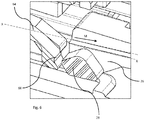
- Figure 6 shows the shape of the first arm end28 and the second arm end 66 enlarged in cut view.
- the first arm end 28 comprises a wedge shape and wherein the intention in the second arm end 66 comprises a v-shaped groove corresponding with the wedge shaped bar.
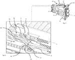
- Figure 7 shows a perspective view of the electrical connector 10 and the counter connector 100 in a mated position.
- Figure 8 shows details of the cavity 30 and connector position assurance device 60 in a released position, in a cut view.
- the connector position assurance device 60 is released by first unlocking means that are attached at the electrical counter connector 100 when the electrical connector 10 and the electrical counter connector 100 are mated.
- the unlocking means comprises a protrusion 115 arranged on a shroud 110 of the electrical counter connector 100.
- the protrusion 115 comes in engagement with the flexible first arm 26 and the flexible second arm 64 thereby flexible deforming the second arm 64 perpendicular to the mating axis and separate the first arm end 28 from the second arm end 66 thereby unlocking the connector position assurance device 60.
- the connector position assurance device 60 is movable to the fourth position P4 along the mating axis X in mating direction.
- Figure. 9 shows a perspective view of the electrical connector 10 in the counter connector 100 in the mated position.
- Figure 10 shows details of the cavity 30 and connector position assurance device 60 in a mated position, in a cut view.
- the connector position assurance device 60 is releasable hold in the fourth position P4 by the second protrusions 70 interacting with the support bar 21.
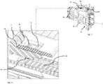
- Figure 11 shows a perspective view of the electrical connector 10 in the counter connector 100 in a mated position.
- Figure 12 shows details of the cavity 30 and connector position assurance device60 in a mated position showing the locking bar, in a cut view.
- the released connector position assurance device 60 securely locks the electrical connector 10 to the electrical counter connector 100 by second locking means, attached on the position assurance device 60, when the connector position assurance device 60 is moved to the fourth position P4.
- the second locking means comprise a locking bar 68 arranged on the connector position assurance device 60 extending along the mating axis X, preventing flexible deformation of the flexible first arm 26 when the connector position assurance device 60 is in the fourth position P4.
Landscapes
- Details Of Connecting Devices For Male And Female Coupling (AREA)
Priority Applications (2)
| Application Number | Priority Date | Filing Date | Title |
|---|---|---|---|
| EP19160455.2A EP3706254B1 (de) | 2019-03-04 | 2019-03-04 | Elektrischer hochspannungssteckverbinder mit auf einem schieber montiertem cpa |
| JP2020035810A JP7460397B2 (ja) | 2019-03-04 | 2020-03-03 | スライダに組み付けられたcpaを備えた高圧電気コネクタ |
Applications Claiming Priority (1)
| Application Number | Priority Date | Filing Date | Title |
|---|---|---|---|
| EP19160455.2A EP3706254B1 (de) | 2019-03-04 | 2019-03-04 | Elektrischer hochspannungssteckverbinder mit auf einem schieber montiertem cpa |
Publications (2)
| Publication Number | Publication Date |
|---|---|
| EP3706254A1 true EP3706254A1 (de) | 2020-09-09 |
| EP3706254B1 EP3706254B1 (de) | 2023-12-27 |
Family
ID=65685215
Family Applications (1)
| Application Number | Title | Priority Date | Filing Date |
|---|---|---|---|
| EP19160455.2A Active EP3706254B1 (de) | 2019-03-04 | 2019-03-04 | Elektrischer hochspannungssteckverbinder mit auf einem schieber montiertem cpa |
Country Status (2)
| Country | Link |
|---|---|
| EP (1) | EP3706254B1 (de) |
| JP (1) | JP7460397B2 (de) |
Families Citing this family (3)
| Publication number | Priority date | Publication date | Assignee | Title |
|---|---|---|---|---|
| JP2023051001A (ja) * | 2021-09-30 | 2023-04-11 | 株式会社オートネットワーク技術研究所 | コネクタ、及びコネクタアセンブリ |
| JP2023050999A (ja) | 2021-09-30 | 2023-04-11 | 株式会社オートネットワーク技術研究所 | コネクタ、及びコネクタアセンブリ |
| JP2023050998A (ja) | 2021-09-30 | 2023-04-11 | 株式会社オートネットワーク技術研究所 | コネクタ、及びコネクタアセンブリ |
Citations (4)
| Publication number | Priority date | Publication date | Assignee | Title |
|---|---|---|---|---|
| US20100227494A1 (en) * | 2005-07-28 | 2010-09-09 | Fci Americas Technology, Llc | Electrical connector assembly with connection assist |
| US9455523B1 (en) * | 2015-08-05 | 2016-09-27 | Delphi Technologies, Inc. | Right angle connection assembly |
| EP3211729A1 (de) * | 2016-02-25 | 2017-08-30 | Dai-Ichi Seiko Co., Ltd. | Elektrischer steckverbinder |
| EP3211730A1 (de) * | 2016-02-25 | 2017-08-30 | Dai-Ichi Seiko Co., Ltd. | Elektrischer steckverbinder |
Family Cites Families (2)
| Publication number | Priority date | Publication date | Assignee | Title |
|---|---|---|---|---|
| JP2015215985A (ja) | 2014-05-09 | 2015-12-03 | 住友電装株式会社 | 嵌合検知コネクタ |
| JP6292481B2 (ja) | 2015-04-29 | 2018-03-14 | 住友電装株式会社 | コネクタ |
-
2019
- 2019-03-04 EP EP19160455.2A patent/EP3706254B1/de active Active
-
2020
- 2020-03-03 JP JP2020035810A patent/JP7460397B2/ja active Active
Patent Citations (4)
| Publication number | Priority date | Publication date | Assignee | Title |
|---|---|---|---|---|
| US20100227494A1 (en) * | 2005-07-28 | 2010-09-09 | Fci Americas Technology, Llc | Electrical connector assembly with connection assist |
| US9455523B1 (en) * | 2015-08-05 | 2016-09-27 | Delphi Technologies, Inc. | Right angle connection assembly |
| EP3211729A1 (de) * | 2016-02-25 | 2017-08-30 | Dai-Ichi Seiko Co., Ltd. | Elektrischer steckverbinder |
| EP3211730A1 (de) * | 2016-02-25 | 2017-08-30 | Dai-Ichi Seiko Co., Ltd. | Elektrischer steckverbinder |
Also Published As
| Publication number | Publication date |
|---|---|
| JP2020145191A (ja) | 2020-09-10 |
| JP7460397B2 (ja) | 2024-04-02 |
| EP3706254B1 (de) | 2023-12-27 |
Similar Documents
| Publication | Publication Date | Title |
|---|---|---|
| KR102556351B1 (ko) | 단자 접촉 보호 수단을 구비한 직각 커넥터 | |
| US6648669B1 (en) | Electrical connection with sequential disconnect | |
| US9455523B1 (en) | Right angle connection assembly | |
| EP2930796A1 (de) | Verbinder mit vibrierender verbindungsrückkopplung | |
| EP3706254B1 (de) | Elektrischer hochspannungssteckverbinder mit auf einem schieber montiertem cpa | |
| EP3823106B1 (de) | Elektrische verbinderanordnung mit verbindungsunterstützung | |
| US10236640B2 (en) | Electrical connector for a safety restraint system | |
| WO2010032088A1 (en) | Electrical connector assembly | |
| US10014619B2 (en) | Angle connector | |
| WO2019027666A1 (en) | CURRENT COMPRESSION BLADE CONNECTION SYSTEM | |
| US8858261B2 (en) | Device for electrically connecting a cable, in particular a plug-in connector part having a shielded contact element | |
| US9225082B2 (en) | Device for electrically connecting a cable, in particular a plug-in connector part | |
| EP2955797A1 (de) | Kabelzugentlastung | |
| JP2018190714A (ja) | 安全システムのためのコネクタアセンブリ | |
| EP3247003A1 (de) | Elektrischer steckverbinder | |
| EP0680116A2 (de) | Steckverbinder mit abgewinkeltem Kabelaustritt und lösbarer Zweifachverriegelung | |
| JP7027242B2 (ja) | 安全システムのためのコネクタアセンブリ | |
| EP4297193A1 (de) | Elektrische verbinderanordnung mit flexiblen und starren anschlussverriegelungsfunktionen | |
| EP0828321A2 (de) | Verbinder für Airbagsystem | |
| EP1701414B1 (de) | Elektrischer Verbinder | |
| EP2887464B1 (de) | Abgeschirmter Verbinder und abgeschirmte Verbinderanordnung | |
| US20180034217A1 (en) | Connector | |
| US9923303B2 (en) | Electrical connector with terminal centering system | |
| CN107453075A (zh) | 用于气囊应用的插塞式连接器 | |
| EP3076492B1 (de) | Elektrisches steckverbindersystem mit seitlich vorstehendem freigabearm |
Legal Events
| Date | Code | Title | Description |
|---|---|---|---|
| PUAI | Public reference made under article 153(3) epc to a published international application that has entered the european phase |
Free format text: ORIGINAL CODE: 0009012 |
|
| STAA | Information on the status of an ep patent application or granted ep patent |
Free format text: STATUS: THE APPLICATION HAS BEEN PUBLISHED |
|
| AK | Designated contracting states |
Kind code of ref document: A1 Designated state(s): AL AT BE BG CH CY CZ DE DK EE ES FI FR GB GR HR HU IE IS IT LI LT LU LV MC MK MT NL NO PL PT RO RS SE SI SK SM TR |
|
| AX | Request for extension of the european patent |
Extension state: BA ME |
|
| STAA | Information on the status of an ep patent application or granted ep patent |
Free format text: STATUS: REQUEST FOR EXAMINATION WAS MADE |
|
| 17P | Request for examination filed |
Effective date: 20210303 |
|
| RBV | Designated contracting states (corrected) |
Designated state(s): AL AT BE BG CH CY CZ DE DK EE ES FI FR GB GR HR HU IE IS IT LI LT LU LV MC MK MT NL NO PL PT RO RS SE SI SK SM TR |
|
| STAA | Information on the status of an ep patent application or granted ep patent |
Free format text: STATUS: EXAMINATION IS IN PROGRESS |
|
| 17Q | First examination report despatched |
Effective date: 20220222 |
|
| RAP3 | Party data changed (applicant data changed or rights of an application transferred) |
Owner name: APTIV TECHNOLOGIES LIMITED |
|
| REG | Reference to a national code |
Ref country code: DE Ref legal event code: R079 Ipc: H01R0013641000 Ref country code: DE Ref legal event code: R079 Ref document number: 602019043844 Country of ref document: DE Free format text: PREVIOUS MAIN CLASS: H01R0013629000 Ipc: H01R0013641000 |
|
| GRAP | Despatch of communication of intention to grant a patent |
Free format text: ORIGINAL CODE: EPIDOSNIGR1 |
|
| STAA | Information on the status of an ep patent application or granted ep patent |
Free format text: STATUS: GRANT OF PATENT IS INTENDED |
|
| RIC1 | Information provided on ipc code assigned before grant |
Ipc: H01R 13/629 20060101ALI20230702BHEP Ipc: H01R 13/641 20060101AFI20230702BHEP |
|
| INTG | Intention to grant announced |
Effective date: 20230719 |
|
| P01 | Opt-out of the competence of the unified patent court (upc) registered |
Effective date: 20231011 |
|
| GRAS | Grant fee paid |
Free format text: ORIGINAL CODE: EPIDOSNIGR3 |
|
| GRAA | (expected) grant |
Free format text: ORIGINAL CODE: 0009210 |
|
| STAA | Information on the status of an ep patent application or granted ep patent |
Free format text: STATUS: THE PATENT HAS BEEN GRANTED |
|
| AK | Designated contracting states |
Kind code of ref document: B1 Designated state(s): AL AT BE BG CH CY CZ DE DK EE ES FI FR GB GR HR HU IE IS IT LI LT LU LV MC MK MT NL NO PL PT RO RS SE SI SK SM TR |
|
| REG | Reference to a national code |
Ref country code: GB Ref legal event code: FG4D |
|
| REG | Reference to a national code |
Ref country code: CH Ref legal event code: EP |
|
| REG | Reference to a national code |
Ref country code: DE Ref legal event code: R096 Ref document number: 602019043844 Country of ref document: DE |
|
| REG | Reference to a national code |
Ref country code: IE Ref legal event code: FG4D |
|
| PG25 | Lapsed in a contracting state [announced via postgrant information from national office to epo] |
Ref country code: GR Free format text: LAPSE BECAUSE OF FAILURE TO SUBMIT A TRANSLATION OF THE DESCRIPTION OR TO PAY THE FEE WITHIN THE PRESCRIBED TIME-LIMIT Effective date: 20240328 |
|
| REG | Reference to a national code |
Ref country code: LT Ref legal event code: MG9D |
|
| PG25 | Lapsed in a contracting state [announced via postgrant information from national office to epo] |
Ref country code: LT Free format text: LAPSE BECAUSE OF FAILURE TO SUBMIT A TRANSLATION OF THE DESCRIPTION OR TO PAY THE FEE WITHIN THE PRESCRIBED TIME-LIMIT Effective date: 20231227 |
|
| PG25 | Lapsed in a contracting state [announced via postgrant information from national office to epo] |
Ref country code: ES Free format text: LAPSE BECAUSE OF FAILURE TO SUBMIT A TRANSLATION OF THE DESCRIPTION OR TO PAY THE FEE WITHIN THE PRESCRIBED TIME-LIMIT Effective date: 20231227 |
|
| PG25 | Lapsed in a contracting state [announced via postgrant information from national office to epo] |
Ref country code: LT Free format text: LAPSE BECAUSE OF FAILURE TO SUBMIT A TRANSLATION OF THE DESCRIPTION OR TO PAY THE FEE WITHIN THE PRESCRIBED TIME-LIMIT Effective date: 20231227 Ref country code: GR Free format text: LAPSE BECAUSE OF FAILURE TO SUBMIT A TRANSLATION OF THE DESCRIPTION OR TO PAY THE FEE WITHIN THE PRESCRIBED TIME-LIMIT Effective date: 20240328 Ref country code: FI Free format text: LAPSE BECAUSE OF FAILURE TO SUBMIT A TRANSLATION OF THE DESCRIPTION OR TO PAY THE FEE WITHIN THE PRESCRIBED TIME-LIMIT Effective date: 20231227 Ref country code: ES Free format text: LAPSE BECAUSE OF FAILURE TO SUBMIT A TRANSLATION OF THE DESCRIPTION OR TO PAY THE FEE WITHIN THE PRESCRIBED TIME-LIMIT Effective date: 20231227 Ref country code: BG Free format text: LAPSE BECAUSE OF FAILURE TO SUBMIT A TRANSLATION OF THE DESCRIPTION OR TO PAY THE FEE WITHIN THE PRESCRIBED TIME-LIMIT Effective date: 20240327 |
|
| REG | Reference to a national code |
Ref country code: NL Ref legal event code: MP Effective date: 20231227 |
|
| REG | Reference to a national code |
Ref country code: AT Ref legal event code: MK05 Ref document number: 1645424 Country of ref document: AT Kind code of ref document: T Effective date: 20231227 |
|
| PG25 | Lapsed in a contracting state [announced via postgrant information from national office to epo] |
Ref country code: NL Free format text: LAPSE BECAUSE OF FAILURE TO SUBMIT A TRANSLATION OF THE DESCRIPTION OR TO PAY THE FEE WITHIN THE PRESCRIBED TIME-LIMIT Effective date: 20231227 |
|
| PG25 | Lapsed in a contracting state [announced via postgrant information from national office to epo] |
Ref country code: SE Free format text: LAPSE BECAUSE OF FAILURE TO SUBMIT A TRANSLATION OF THE DESCRIPTION OR TO PAY THE FEE WITHIN THE PRESCRIBED TIME-LIMIT Effective date: 20231227 Ref country code: RS Free format text: LAPSE BECAUSE OF FAILURE TO SUBMIT A TRANSLATION OF THE DESCRIPTION OR TO PAY THE FEE WITHIN THE PRESCRIBED TIME-LIMIT Effective date: 20231227 Ref country code: NO Free format text: LAPSE BECAUSE OF FAILURE TO SUBMIT A TRANSLATION OF THE DESCRIPTION OR TO PAY THE FEE WITHIN THE PRESCRIBED TIME-LIMIT Effective date: 20240327 Ref country code: NL Free format text: LAPSE BECAUSE OF FAILURE TO SUBMIT A TRANSLATION OF THE DESCRIPTION OR TO PAY THE FEE WITHIN THE PRESCRIBED TIME-LIMIT Effective date: 20231227 Ref country code: LV Free format text: LAPSE BECAUSE OF FAILURE TO SUBMIT A TRANSLATION OF THE DESCRIPTION OR TO PAY THE FEE WITHIN THE PRESCRIBED TIME-LIMIT Effective date: 20231227 Ref country code: HR Free format text: LAPSE BECAUSE OF FAILURE TO SUBMIT A TRANSLATION OF THE DESCRIPTION OR TO PAY THE FEE WITHIN THE PRESCRIBED TIME-LIMIT Effective date: 20231227 |
|
| PG25 | Lapsed in a contracting state [announced via postgrant information from national office to epo] |
Ref country code: IS Free format text: LAPSE BECAUSE OF FAILURE TO SUBMIT A TRANSLATION OF THE DESCRIPTION OR TO PAY THE FEE WITHIN THE PRESCRIBED TIME-LIMIT Effective date: 20240427 |
|
| PG25 | Lapsed in a contracting state [announced via postgrant information from national office to epo] |
Ref country code: CZ Free format text: LAPSE BECAUSE OF FAILURE TO SUBMIT A TRANSLATION OF THE DESCRIPTION OR TO PAY THE FEE WITHIN THE PRESCRIBED TIME-LIMIT Effective date: 20231227 Ref country code: AT Free format text: LAPSE BECAUSE OF FAILURE TO SUBMIT A TRANSLATION OF THE DESCRIPTION OR TO PAY THE FEE WITHIN THE PRESCRIBED TIME-LIMIT Effective date: 20231227 |
|
| PG25 | Lapsed in a contracting state [announced via postgrant information from national office to epo] |
Ref country code: SK Free format text: LAPSE BECAUSE OF FAILURE TO SUBMIT A TRANSLATION OF THE DESCRIPTION OR TO PAY THE FEE WITHIN THE PRESCRIBED TIME-LIMIT Effective date: 20231227 |
|
| PG25 | Lapsed in a contracting state [announced via postgrant information from national office to epo] |
Ref country code: SM Free format text: LAPSE BECAUSE OF FAILURE TO SUBMIT A TRANSLATION OF THE DESCRIPTION OR TO PAY THE FEE WITHIN THE PRESCRIBED TIME-LIMIT Effective date: 20231227 Ref country code: SK Free format text: LAPSE BECAUSE OF FAILURE TO SUBMIT A TRANSLATION OF THE DESCRIPTION OR TO PAY THE FEE WITHIN THE PRESCRIBED TIME-LIMIT Effective date: 20231227 Ref country code: RO Free format text: LAPSE BECAUSE OF FAILURE TO SUBMIT A TRANSLATION OF THE DESCRIPTION OR TO PAY THE FEE WITHIN THE PRESCRIBED TIME-LIMIT Effective date: 20231227 Ref country code: IT Free format text: LAPSE BECAUSE OF FAILURE TO SUBMIT A TRANSLATION OF THE DESCRIPTION OR TO PAY THE FEE WITHIN THE PRESCRIBED TIME-LIMIT Effective date: 20231227 Ref country code: IS Free format text: LAPSE BECAUSE OF FAILURE TO SUBMIT A TRANSLATION OF THE DESCRIPTION OR TO PAY THE FEE WITHIN THE PRESCRIBED TIME-LIMIT Effective date: 20240427 Ref country code: EE Free format text: LAPSE BECAUSE OF FAILURE TO SUBMIT A TRANSLATION OF THE DESCRIPTION OR TO PAY THE FEE WITHIN THE PRESCRIBED TIME-LIMIT Effective date: 20231227 Ref country code: CZ Free format text: LAPSE BECAUSE OF FAILURE TO SUBMIT A TRANSLATION OF THE DESCRIPTION OR TO PAY THE FEE WITHIN THE PRESCRIBED TIME-LIMIT Effective date: 20231227 Ref country code: AT Free format text: LAPSE BECAUSE OF FAILURE TO SUBMIT A TRANSLATION OF THE DESCRIPTION OR TO PAY THE FEE WITHIN THE PRESCRIBED TIME-LIMIT Effective date: 20231227 |
|
| PG25 | Lapsed in a contracting state [announced via postgrant information from national office to epo] |
Ref country code: PT Free format text: LAPSE BECAUSE OF FAILURE TO SUBMIT A TRANSLATION OF THE DESCRIPTION OR TO PAY THE FEE WITHIN THE PRESCRIBED TIME-LIMIT Effective date: 20240429 Ref country code: PL Free format text: LAPSE BECAUSE OF FAILURE TO SUBMIT A TRANSLATION OF THE DESCRIPTION OR TO PAY THE FEE WITHIN THE PRESCRIBED TIME-LIMIT Effective date: 20231227 |
|
| PG25 | Lapsed in a contracting state [announced via postgrant information from national office to epo] |
Ref country code: PT Free format text: LAPSE BECAUSE OF FAILURE TO SUBMIT A TRANSLATION OF THE DESCRIPTION OR TO PAY THE FEE WITHIN THE PRESCRIBED TIME-LIMIT Effective date: 20240429 Ref country code: PL Free format text: LAPSE BECAUSE OF FAILURE TO SUBMIT A TRANSLATION OF THE DESCRIPTION OR TO PAY THE FEE WITHIN THE PRESCRIBED TIME-LIMIT Effective date: 20231227 |
|
| REG | Reference to a national code |
Ref country code: DE Ref legal event code: R097 Ref document number: 602019043844 Country of ref document: DE |
|
| PG25 | Lapsed in a contracting state [announced via postgrant information from national office to epo] |
Ref country code: DK Free format text: LAPSE BECAUSE OF FAILURE TO SUBMIT A TRANSLATION OF THE DESCRIPTION OR TO PAY THE FEE WITHIN THE PRESCRIBED TIME-LIMIT Effective date: 20231227 |
|
| RAP2 | Party data changed (patent owner data changed or rights of a patent transferred) |
Owner name: APTIV TECHNOLOGIES AG |
|
| PG25 | Lapsed in a contracting state [announced via postgrant information from national office to epo] |
Ref country code: DK Free format text: LAPSE BECAUSE OF FAILURE TO SUBMIT A TRANSLATION OF THE DESCRIPTION OR TO PAY THE FEE WITHIN THE PRESCRIBED TIME-LIMIT Effective date: 20231227 |
|
| REG | Reference to a national code |
Ref country code: CH Ref legal event code: PL |
|
| PLBE | No opposition filed within time limit |
Free format text: ORIGINAL CODE: 0009261 |
|
| STAA | Information on the status of an ep patent application or granted ep patent |
Free format text: STATUS: NO OPPOSITION FILED WITHIN TIME LIMIT |
|
| PG25 | Lapsed in a contracting state [announced via postgrant information from national office to epo] |
Ref country code: LU Free format text: LAPSE BECAUSE OF NON-PAYMENT OF DUE FEES Effective date: 20240304 |
|
| PG25 | Lapsed in a contracting state [announced via postgrant information from national office to epo] |
Ref country code: MC Free format text: LAPSE BECAUSE OF FAILURE TO SUBMIT A TRANSLATION OF THE DESCRIPTION OR TO PAY THE FEE WITHIN THE PRESCRIBED TIME-LIMIT Effective date: 20231227 |
|
| PG25 | Lapsed in a contracting state [announced via postgrant information from national office to epo] |
Ref country code: MC Free format text: LAPSE BECAUSE OF FAILURE TO SUBMIT A TRANSLATION OF THE DESCRIPTION OR TO PAY THE FEE WITHIN THE PRESCRIBED TIME-LIMIT Effective date: 20231227 Ref country code: LU Free format text: LAPSE BECAUSE OF NON-PAYMENT OF DUE FEES Effective date: 20240304 |
|
| 26N | No opposition filed |
Effective date: 20240930 |
|
| REG | Reference to a national code |
Ref country code: BE Ref legal event code: MM Effective date: 20240331 |
|
| PG25 | Lapsed in a contracting state [announced via postgrant information from national office to epo] |
Ref country code: BE Free format text: LAPSE BECAUSE OF NON-PAYMENT OF DUE FEES Effective date: 20240331 |
|
| PG25 | Lapsed in a contracting state [announced via postgrant information from national office to epo] |
Ref country code: IE Free format text: LAPSE BECAUSE OF NON-PAYMENT OF DUE FEES Effective date: 20240304 |
|
| PG25 | Lapsed in a contracting state [announced via postgrant information from national office to epo] |
Ref country code: IE Free format text: LAPSE BECAUSE OF NON-PAYMENT OF DUE FEES Effective date: 20240304 Ref country code: BE Free format text: LAPSE BECAUSE OF NON-PAYMENT OF DUE FEES Effective date: 20240331 Ref country code: CH Free format text: LAPSE BECAUSE OF NON-PAYMENT OF DUE FEES Effective date: 20240331 |
|
| PG25 | Lapsed in a contracting state [announced via postgrant information from national office to epo] |
Ref country code: SI Free format text: LAPSE BECAUSE OF FAILURE TO SUBMIT A TRANSLATION OF THE DESCRIPTION OR TO PAY THE FEE WITHIN THE PRESCRIBED TIME-LIMIT Effective date: 20231227 |
|
| PG25 | Lapsed in a contracting state [announced via postgrant information from national office to epo] |
Ref country code: CY Free format text: LAPSE BECAUSE OF FAILURE TO SUBMIT A TRANSLATION OF THE DESCRIPTION OR TO PAY THE FEE WITHIN THE PRESCRIBED TIME-LIMIT; INVALID AB INITIO Effective date: 20190304 |
|
| PG25 | Lapsed in a contracting state [announced via postgrant information from national office to epo] |
Ref country code: HU Free format text: LAPSE BECAUSE OF FAILURE TO SUBMIT A TRANSLATION OF THE DESCRIPTION OR TO PAY THE FEE WITHIN THE PRESCRIBED TIME-LIMIT; INVALID AB INITIO Effective date: 20190304 |
|
| PG25 | Lapsed in a contracting state [announced via postgrant information from national office to epo] |
Ref country code: TR Free format text: LAPSE BECAUSE OF FAILURE TO SUBMIT A TRANSLATION OF THE DESCRIPTION OR TO PAY THE FEE WITHIN THE PRESCRIBED TIME-LIMIT Effective date: 20231227 |
|
| PGFP | Annual fee paid to national office [announced via postgrant information from national office to epo] |
Ref country code: GB Payment date: 20260204 Year of fee payment: 8 |
|
| PGFP | Annual fee paid to national office [announced via postgrant information from national office to epo] |
Ref country code: DE Payment date: 20260223 Year of fee payment: 8 |
|
| PGFP | Annual fee paid to national office [announced via postgrant information from national office to epo] |
Ref country code: FR Payment date: 20260205 Year of fee payment: 8 |