EP3707325B1 - Cadenas pour bicyclette compact - Google Patents
Cadenas pour bicyclette compact Download PDFInfo
- Publication number
- EP3707325B1 EP3707325B1 EP19846907.4A EP19846907A EP3707325B1 EP 3707325 B1 EP3707325 B1 EP 3707325B1 EP 19846907 A EP19846907 A EP 19846907A EP 3707325 B1 EP3707325 B1 EP 3707325B1
- Authority
- EP
- European Patent Office
- Prior art keywords
- lock
- width
- plate portion
- crossbar
- bevel
- Prior art date
- Legal status (The legal status is an assumption and is not a legal conclusion. Google has not performed a legal analysis and makes no representation as to the accuracy of the status listed.)
- Active
Links
Images




Classifications
-
- E—FIXED CONSTRUCTIONS
- E05—LOCKS; KEYS; WINDOW OR DOOR FITTINGS; SAFES
- E05B—LOCKS; ACCESSORIES THEREFOR; HANDCUFFS
- E05B67/00—Padlocks; Details thereof
- E05B67/06—Shackles; Arrangement of the shackle
- E05B67/063—Padlocks with removable shackles
-
- E—FIXED CONSTRUCTIONS
- E05—LOCKS; KEYS; WINDOW OR DOOR FITTINGS; SAFES
- E05B—LOCKS; ACCESSORIES THEREFOR; HANDCUFFS
- E05B67/00—Padlocks; Details thereof
- E05B67/06—Shackles; Arrangement of the shackle
-
- E—FIXED CONSTRUCTIONS
- E05—LOCKS; KEYS; WINDOW OR DOOR FITTINGS; SAFES
- E05B—LOCKS; ACCESSORIES THEREFOR; HANDCUFFS
- E05B67/00—Padlocks; Details thereof
- E05B67/06—Shackles; Arrangement of the shackle
- E05B67/22—Padlocks with sliding shackles, with or without rotary or pivotal movement
- E05B67/24—Padlocks with sliding shackles, with or without rotary or pivotal movement with built- in cylinder locks
Definitions
- the present disclosure generally relates to portable locks.
- Portable locks for securing bicycles frequently include a crossbar and a U-shaped shackle that is removably coupled to the crossbar via a locking mechanism seated in the crossbar.
- These locks often referred to as "U-locks" owing to the shape of the shackle, are typically able to provide favorable levels of security at a relatively low weight in comparison to certain other forms of portable locks, such as those involving chains or articulating shackles.
- these U-locks are not without their drawbacks.
- the large size and rigid nature of the U-shaped shackle may render the lock difficult to carry when not in use, and may hinder the use of the lock in tight or cramped spaces.
- U-locks Another area of concern for U-locks is susceptibility to saw attacks, as the elongated and exposed shackle provides the attacker with a relatively large space in which to work the saw.
- the elongated legs naturally provide a large lever arm with which the locking mechanism can be pried.
- the shackles may also facilitate twisting attacks, in which a pry bar placed between the crossbar and the shackle is twisted to expand the opening formed by the cut.
- U.S. Patent No. US 4,112,716 A discloses a lock in accordance with the preamble of claim 1. Further examples of locks are disclosed in French Patent Publication No. FR 2 739 890 A1 and German Patent No. DE 810 961 C .
- An exemplary shackle is configured for use with a crossbar having a pair of openings and a locking mechanism including a pair of deadbolts.
- the shackle includes a substantially flat plate portion having a length in a longitudinal direction, a width in a transverse direction, and a thickness along a lateral axis defining a proximal direction and a distal direction. The length is greater than the width, which is greater than the thickness.
- the shackle further includes a pair of longitudinally-offset legs extending distally from the plate portion. Each leg has a diameter, and includes a bumper and a notch positioned distally of the bumper. An offset distance is defined between the distal surface of the plate portion and the distal faces of the bumpers. The width of the plate portion is greater than each of the diameter and the offset distance.
- references in the specification to "one embodiment,” “an embodiment,” “an illustrative embodiment,” etc., indicate that the embodiment described may include a particular feature, structure, or characteristic, but every embodiment may or may not necessarily include that particular feature, structure, or characteristic. Moreover, such phrases are not necessarily referring to the same embodiment. It should further be appreciated that although reference to a "preferred" component or feature may indicate the desirability of a particular component or feature with respect to an embodiment, the disclosure is not so limiting with respect to other embodiments, which may omit such a component or feature.
- items included in a list in the form of "at least one of A, B, and C” can mean (A); (B); (C); (A and B); (B and C); (A and C); or (A, B, and C).
- items listed in the form of "at least one of A, B, or C” can mean (A); (B); (C); (A and B); (B and C); (A and C); or (A, B, and C).
- the terms “longitudinal,” “lateral,” and “transverse” are used to denote motion or spacing along three mutually perpendicular axes.
- the X-axis defines the longitudinal directions
- the Y-axis defines the lateral directions
- the Z-axis defines the transverse directions.
- the descriptions that follow may refer to the directions defined by the axes with specific reference to the orientations illustrated in the Figures.
- the lateral (Y) directions may be referred to as proximal and distal directions or upward and downward directions. These terms are used for ease and convenience of description, and are without regard to the orientation of the system with respect to the environment.
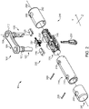
- the lock 90 generally includes a shackle 100 and a crossbar 200 to which the shackle 100 is selectively coupled.
- the shackle 100 generally includes a longitudinally-extending plate portion 110 and a pair of longitudinally-spaced legs 120 extending from the plate portion 110 in a lateral direction, and may further include bumpers 130 and/or a cover 140 ( FIGS. 6 and 7 ).
- the crossbar 200 extends along a crossbar longitudinal axis 202, and generally includes a tube 210, a housing 220 seated in the tube 210, a locking mechanism 230 in the tube 210 and engaged with the shackle 100, and a cover assembly 240 mounted to the outer side of the tube 210.
- the plate portion 110 extends along a longitudinal (X) axis 102, and includes a pair of longitudinally-spaced openings 112, each of which extends through the plate portion 110 along a corresponding and respective lateral (Y) axis 104.
- Each of the openings 112 includes a step 113 such that the laterally-outward or upper portion of each opening 112 is larger than the laterally-inward or lower portion of each opening 112.
- the plate portion 110 includes a pair of enlarged end portions 114 through which the pair of openings 112 extend, and further includes a narrowed central portion 116 extending between and connecting the enlarged end portions 114.
- the enlarged end portions 114 are wider than the narrowed central portion 116 in the transverse (Z) dimension.
- the plate portion 110 also has a proximal or upper surface 118 and a distal or lower surface 119, and the openings 112 extend laterally through the surfaces 118, 119 and the space therebetween.
- Each leg 120 includes a base portion 122 including a shoulder 123, a second portion 124 extending distally from the base portion 122, and a foot portion 125 extending distally from the second portion 124.
- the base portion 122 is configured to be received in the opening 112, and includes a shoulder 123 such that the laterally-outward or upper portion of each base portion 122 is larger than the laterally-inward or lower portion of each base portion 122.
- the shoulder 123 is configured to abut the step 113 to seat the base portion 122 in the opening 112 while preventing the leg 120 from being passed entirely through the opening 112.
- the engagement features are configured to engage the crossbar 200 to aid in constraining the legs 120 relative to the crossbar 200 in various degrees of freedom.
- Each foot 125 includes a notch 126 having a ramp 127 that is configured to engage the locking mechanism 230 in order to selectively prevent removal of the shackle 100 from the crossbar 200.
- Each foot 125 further includes a double-beveled recess 128, which is beveled about two axes. More particularly, the recess 128 is beveled about the lateral (Y) axis such that the tip 129 of the foot 125 takes the shape of a crescent moon. At least an upper portion of the recess 128 is further beveled about a transverse (Z) axis, which provides that portion with a geometry similar to that of an octant of a sphere or ellipsoid.
- the shackle 100 may further include one or more resilient bumpers 130, and in the illustrated form includes two bumpers 130 formed of an elastic material, such as rubber.
- Each bumper 130 is mounted to the second portion 124 of a corresponding leg 120 such that the leg 120 extends through a central opening 132 of the bumper 130.
- the bumpers 130 may be secured to the legs 120 using adhesives, while in other forms such adhesives may be unnecessary.
- the resilient material of the bumpers 130 may attenuate shocks resulting from the shackle 100 being rapidly inserted to the crossbar 200, and may aid in discouraging objects from entering the crossbar openings when the shackle 100 is coupled to the crossbar 200.
- Each bumper has an upper or proximal face 138 and an opposite lower or distal face 139, and the opening extends laterally through the faces 138, 139 and the space therebetween.
- the shackle 100 may further include a protective cover 140 that covers the plate portion 110 and a portion of each leg 120.
- the cover 140 extends distally from the plate portion 110 to the upper faces 138 of the bumpers 130, thereby providing a backstop that prevents proximal movement of the bumpers 130 along the legs 120.
- the cover 140 is provided in the form of a sleeve 140 that provides for increased resistance to attack and tampering.
- the sleeve 140 may, for example, be formed of a hardened steel that is resistant to saw attacks.
- the cover 140 may comprise a coating formed of a low-durometer material, such as a material comprising at least one of a plastic, a rubber, or a polymer.
- the cover 140 includes an upper or proximal surface 148 adjacent the plate portion upper surface 118, and a lower or distal surface 149 adjacent the plate portion lower surface 119.
- the legs 120 are oriented such that the engagement features face one another, and the tip portions 129 are passed through the openings 112 such that the base portions 122 enter the openings 112 and the shoulders 123 abut the steps 113.
- the base portions 122 and the openings 112 may be configured to aid in the bringing the legs 120 to the appropriate orientation relative to the plate portion 110.
- the shoulder 123 may be formed by a spline
- the step 113 may be formed by a slot operable to receive the spline.
- the slot and the spline may be oriented such that when the base portions 122 are received in the openings 112 and the splines are received in the slots, the crossbar-engaging features of the two legs 120 face one another.
- the legs 120 are secured to the plate portion 110.
- the legs 120 may be welded to the plate portion 110.
- the legs 120 may be securely joined to the plate portion 110 in additional or alternative manners, such as those including adhesion, swaging, staking, fusing, or other techniques.
- the plate portion 110 and the legs 120 may be provided as an integrally formed and monolithic structure, such as by machining the joined components from a single contiguous block of material, or by casting or forging the joined components as a single structure.
- the legs 120 may be fixedly, immovably, and non-rotatably coupled with the plate portion 110.
- the plate portion 110 prevents relative movement of the legs 120 in all degrees of freedom.
- the crossbar 200 defines a pair of openings 208 sized and shaped to closely receive the feet 125 of the shackle 100.
- the openings 208 are defined in part by the tube 210, and more particularly by a set of apertures formed in the tube 210.
- a first pair of spaced-apart apertures 212 are formed in an upper side of the tube 210, and a second pair of spaced-apart apertures 214 are formed diametrically opposite the first pair of apertures 212.
- the openings 208 are further defined by the housing 220, which includes a corresponding set of openings 228 that are aligned with the tube apertures 212, 214.
- Each housing opening 228 is defined in part by a double-beveled wall 227 having a geometry corresponding to that of the beveled recess 128, and each of the second apertures 214 has a crescent-shaped geometry corresponding to that of the tips 129 of the shackle feet 125.
- the tube 210 and the housing 220 are secured to one another, for example using press-fit pins 209, thereby maintaining alignment of the elements defining which the openings 208.
- the locking mechanism 230 extends along a central lateral axis 204, and is operable by a key 231.
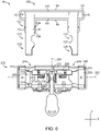
- the locking mechanism 230 generally includes a lock cylinder 232, a cam 234 mounted to a spindle of the lock cylinder 230, a pair of deadbolts 236 slidably captured between the housing 220 and the inner surface of the tube 210.
- the lock cylinder 232 is mounted to the housing 220, and is aligned with an aperture 213 that is formed in the tube 210 and through which the key 231 can be inserted to the lock cylinder 230.
- the locking mechanism 230 further includes a pair of springs 238 longitudinally biasing the deadbolts 236 in a direction away from the central lateral axis 204.
- a pin 237 may be mounted to each deadbolt 236, and the springs 238 may be captured between the pins 237 and walls of the housing 220 to bias the deadbolts 236 longitudinally outward.
- longitudinal directions leading away from the central lateral axis 204 may be referred to herein as longitudinally outward directions, and longitudinal directions leading toward the central lateral axis 204 may be referred to herein as longitudinally inward directions.
- longitudinal directions leading toward the central lateral axis 204 may be referred to herein as longitudinally inward directions.
- one spring 238 biases the right-hand deadbolt 236 in the illustrated rightward direction and the other spring 238 biases the left-hand deadbolt 236 in the illustrated leftward direction
- each of the springs 238 biases the corresponding deadbolt 236 in its longitudinally-outward direction.
- the cam 234 has a longer dimension and a shorter dimension, and is rotatable between a locking position and an unlocking position.
- the longer dimension is aligned with the deadbolts 236, and retains the deadbolts 236 in the extended positions thereof.
- the unlocking position the shorter dimension of the cam 234 is aligned with the deadbolts 236.
- the deadbolts 236 can be urged from their extended positions to their retracted positions, for example upon insertion of the feet 125 into the openings 208.
- the cover assembly 240 provides a protective outer shell for the crossbar 200, and generally includes a first sleeve 241, a second sleeve 242, and a dust cover 246 including a slider 247.
- Each of the sleeves 241, 242 includes a set of apertures 243 that are generally aligned with the tube apertures 212, 214, and which partially define the crossbar openings 208.
- the second sleeve 242 further includes an additional aperture 244 that is aligned with the lock cylinder 232, and through which the key 231 can be inserted to the lock cylinder 232.
- the dust cover 246 includes a corresponding aperture 248, and the slider 247 is operable to slide over the aperture 248 to discourage the entry of debris into the lock cylinder 232.
- the illustrated cover assembly 240 is configured to provide for increased resistance to attack and tampering.
- the sleeves 241, 242 may, for example, be formed of a hardened steel that is resistant to saw attacks.
- the shackle 100 may be attached to the crossbar 200 to define an enclosed hoop 92 that may be used to secure a movable object to a stationary object. To do so, a portion of each object is placed within the area that will be enclosed by the hoop 92.
- the key 231 is inserted into the lock cylinder 232 and rotated to place the cam 234 in its unlocking position, and the feet 125 are inserted into the crossbar openings 208. As the feet 125 enter the openings 208, the beveled recesses 128 urge the deadbolts 236 longitudinally inward against the biasing force of the springs 238.
- the tips 129 enter the second apertures 214, and the bumpers 130 approach the outer surface of the crossbar 200.
- the springs 238 urge the deadbolts 236 into engagement with the notches 126. In this state, the shackle 100 is latched to the crossbar 200, and the lock 90 is in a latched state.
- the key 231 may be rotated to return the cam 234 to its locking position, thereby moving the lock 90 to a locked state.
- the long dimension of the cam 234 is aligned with the deadbolts 236 such that the cam 234 retains the deadbolts 236 in the extended or longitudinally outward positions thereof.
- the deadbolts 236 engage the ramps 127 of the notches 126, thereby preventing removal of the feet 125 from the openings 208.
- the lock 90 can be returned to the latched state by inserting and rotating the key 231, thereby moving the cam 234 to its unlocking position.
- the shackle 100 and crossbar 200 can be separated by pulling the components apart from one another. Such relative movement of the shackle 100 and crossbar 200 causes the ramps 127 to urge the deadbolts 236 to the longitudinally inward against the force of the springs 238, thereby driving the deadbolts 236 to the retracted positions thereof.
- certain features of the assembled lock 90 may aid in discouraging or defeating one or more types of attack or tampering.
- various dimensions 300 of the lock 90 may aid in providing resistance to certain forms of attack. While other forms are contemplated, in the illustrated embodiment, the maximum transverse width 304 of the plate portion 110 is greater than the offset dimension 302 defined between the plate portion 110 and the crossbar 200, and the offset dimension 302 is substantially constant. Additionally, the minimum transverse width 306 of the plate portion 110 is greater than the diameter 308 of the legs 120, and corresponds to the offset dimension 302. The significance of these and other relative dimensions will become apparent in light of the following.
- the lock 90 has various dimensions that may aid in rendering such forms of attack more difficult.
- One dimension is the exposed length 302 of the legs 120, which corresponds to the distance by which the bottom surface 119 of the plate portion 110 is offset from the top surface of the crossbar 200. This dimension 302 may equivalently be measured between the bottom surface 119 of the plate portion 110 and the bottom face 139 of the bumper 130, and may alternatively be referred to as the offset dimension 302.
- This exposed length 302 is much less than the corresponding dimension in conventional U-locks, which may make the attack more difficult.
- the close proximity of the plate portion 110 and the crossbar 200 may hinder the use of powered saws, which typically require more clearance than provided between the plate portion 110 and the crossbar 200.
- the offset dimension 302 may be one inch or less.
- the attacker may attempt to saw through the plate portion 110.
- the transverse width dimensions of the plate portion 110 are selected to discourage such an attack. More particularly, the maximum transverse width 304 of the plate portion (i.e., the width at the thickest portion of the enlarged sections 114) is greater than the minimum transverse width 306 of the plate portion 110 (i.e., the width at the thinnest portion of the narrowed section 116), which is greater than the diameter 308 of the second portions 124 of the legs 120.
- each stroke of the blade may need to remove more material than would be required if attacking the leg 120, which may increase the amount of time required to form a cut of a given depth.
- the lateral thickness 310 of the plate portion 110 may be selected such that the minimum cross-sectional area of the narrowed section 116 is greater than the cross-sectional area of the exposed portions of the legs 120. As a result, more material must be removed to complete the cut, which further hinders the attack.
- the attacker must increase the size of the cut opening to a size sufficient to move at least one of the objects outside the hoop 92.
- the attacker may attempt to do so by pivoting the cut portions of the shackle 100 in opposite directions about the lateral axes 104. With each of the cut segments of the plate portion 110 securely fixed to the base portion 122 of the corresponding leg 120, these torques are transmitted to the crossbar 200 via the feet 125. These torques are partially counteracted by the locking assembly 230, which retains the deadbolts 236 in the extended positions thereof. Further torque resistance is provided by each of the tube 210 and the housing 220.
- the crescent-shaped tips 129 of the feet 125 engage the correspondingly-shaped walls defining the second apertures 214 and the housing openings 228, such that both the tube 210 and the housing 220 resist rotation of the legs 120 about the lateral axes 104.
- the attacker may additionally or alternatively attempt to separate the cut sections of the plate portion 110 from one another by twisting the legs 120 in opposite directions about the longitudinal axis 202 of the crossbar 200.
- the length of the lever arms defined by the legs 120 correspond to the amount of torque that will be generated by a given force, as well as the linear separation that will result from a given degree of twisting.
- the short exposed dimension 302 of the legs 120 aids in reducing both the amount of torque that can be applied and the degree of separation resulting from such torque.
- the short length of the offset dimension 302 hinders the insertion of a pry bar between the plate portion 110 and the crossbar, as may be attempted by a person intending to provide additional leverage for the twist attack.
- Certain additional relative dimensions of the shackle may provide further attack resistance along lines similar to those set forth above.
- one area of engagement that may provide a pivot point during twist attacks is the interface between the tips 129 and the crescent-shaped apertures 214 of the tube.
- the lever arm available for such an attack is limited to a length corresponding to the lateral length dimension 312 of the legs 120, which is less than the longitudinal length dimension 311 of the plate portion 110.
- Another area of engagement that may provide a pivot point during twist attacks is the interface between the deadbolts 236 and the upper surface of the notches 126.
- the lever arm available for such an attack is limited to a length corresponding to the distance 316 between the plate portion 110 and the notch 126, which corresponds to the maximum transverse width 304 of the plate portion 110.
- the dimensions of the cover 140 may be included in or omitted when determining the dimensions described herein. Additionally, the inclusion or omission of the dimensions of the cover 140 may depend upon whether or not the dimension in question provides appreciable resistance to saw and/or twist attacks.
- portions of the cover 140 that are formed of a low-durometer material e.g., a rubber or plastic coating
- those portions formed of a high-durometer metal e.g., hardened steel
- the minimum transverse width 306 of the plate portion 110 is greater than the diameter 308 of the second portions 124 of the legs 120.
- the minimum transverse width 306' of the plate portion 110 is greater than the diameter 308' of the second portions 124 of the legs 120.
- a cross-section may be described with reference to the direction that is orthogonal to the plane along which the cross-section is taken.
- a cross-section taken along a plane including the longitudinal axes 102, 202 and the lateral axes 104 may be described as a transverse cross-section, as the transverse direction is orthogonal to the longitudinal and lateral directions.
- the cross-sections illustrated in FIGS. 4 and 6 are referred to as transverse cross-sections
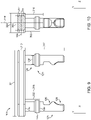
- the cross-section illustrated in FIG. 9 is referred to as a longitudinal cross-section.
- the longitudinal cross-section of the plate portion ( FIG. 10 ) is substantially rectangular. It is also contemplated that the plate portion 110 may have another cross-sectional geometry.
- the plate portion 110 may have a pentagonal cross-sectional geometry in which the upper surface 118 includes a vertex of the pentagon, which may make saw attacks more difficult to execute.
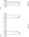
- FIG. 11 is a front view of the shackle 100, which exhibits mirror-image symmetry relative to a central longitudinal-lateral (X-Y) plane. Accordingly, FIG. 11 is also a rear view of the shackle 100.
- FIG. 12 is a right-side view of the shackle 100, which exhibits mirror-image symmetry relative to a central lateral-transverse (Y-X) plane. Accordingly, FIG. 12 is also a leftside view of the shackle 100.
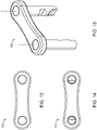
- FIG. 13 is a top-down view of the shackle 100
- FIG. 14 is a bottom-up view of the shackle 100
- FIG. 15 is an isometric view of the shackle 100.
- the bumpers 130 and cover 140 are omitted from FIGS. 11-15 .
Landscapes
- Hooks, Suction Cups, And Attachment By Adhesive Means (AREA)
- Lock And Its Accessories (AREA)
Claims (15)
- Un cadenas (90), comprenant :une manille (100) comprenant :une portion formant plaque (110) présentant une longueur (311) dans une direction longitudinale, une épaisseur (310 ; 310') dans une direction latérale, et une première largeur (304 ; 304') dans une direction transversale, dans lequel la longueur (311) est supérieure à la première largeur (304, 304') ; etune paire de jambes décalées longitudinalement (120) s'étendant à partir de la portion formant plaque (110) dans la direction latérale, dans lequel les jambes (120) sont fixement et immobilement solidaires de la portion formant plaque (110), et dans lequel la portion formant plaque (110) empêche un déplacement relatif des jambes (120) ;dans lequel chaque jambe (120) de la paire de jambes décalées longitudinalement (120) comprend un pied correspondant et respectif (125), et dans lequel chaque pied (125) comprend une encoche correspondante et respective (126) ; etune barre transversale (200) comprenant :une paire d'ouvertures décalées longitudinalement (208), dans lequel chaque pied (125) est reçu dans l'une correspondante et respective des ouvertures (208) ;une paire de pênes dormants (236), dans lequel chaque pêne dormant (236) est dans une position étendue dans laquelle le pêne dormant (236) est engagé dans l'encoche (126) d'un pied correspondant et respectif (125) ; etun mécanisme de verrouillage (230) configuré de sorte à retenir sélectivement les pênes dormants (236) dans leur position étendue, rendant ainsi sélectivement solidaire la manille (100) de la barre transversale (200) ;dans lequel la portion formant plaque (110) est en usage décalée par rapport à la barre transversale (200) d'une distance de décalage (302 ; 302') telle qu'une portion de chaque jambe (120) est exposée, et dans lequel une portion exposée de chaque jambe (120) présente un diamètre (308 ; 308') ;dans lequel la première largeur (304 ; 304') de la portion formant plaque (110) est supérieure au diamètre (308 ; 308') de la portion exposée de chaque jambe (120) ;caractérisé en ce quela première largeur (304 ; 304') est supérieure à l'épaisseur (310 ; 310') ;dans lequel la première largeur (304 ; 304') de la portion formant plaque (110) est supérieure à la distance de décalage (302 ; 302').
- Le cadenas (90) selon la revendication 1, dans lequel la portion formant plaque (110) comprend une portion élargie (114) présentant la première largeur (304 ; 304') et une portion rétrécie (116) présentant une seconde largeur (306 ; 306') inférieure à la première largeur (304 ; 304'), et dans lequel la seconde largeur (306 ; 306') est supérieure au diamètre (308 ; 308') de la portion exposée de chaque jambe (120).
- Le cadenas (90) selon la revendication 2, dans lequel l'épaisseur (310 ; 310'), la seconde largeur (306 ; 306') et le diamètre (308 ; 308') sont sélectionnés de telle sorte qu'une section longitudinale de la portion rétrécie (116) présente une surface supérieure à une section latérale de la portion exposée.
- Le cadenas (90) selon la revendication 2, dans lequel la distance de décalage (302 ; 302') n'est pas plus grande que la seconde largeur (306 ; 306').
- Le cadenas (90) selon la revendication 1, dans lequel chaque pied (125) comprend un renfoncement à double biseau (128), dans lequel le renfoncement à double biseau (128) est défini en partie par un premier biseau configuré de sorte à contraindre les pênes dormants (236) l'un vers l'autre à mesure que les pieds (125) sont insérés dans les ouvertures (208) formées dans la barre transversale (200), dans lequel le renfoncement à double biseau (128) est défini en outre par un second biseau procurant à une terminaison (129) du pied (125) une section transversale en forme de croissant, dans lequel la barre transversale (200) comprend une paire d'ouvertures en forme de croissant (214), et dans lequel les terminaisons (129) des pieds (125) sont reçues dans les ouvertures en forme de croissant (214) de sorte à verrouiller en rotation mutuellement chaque jambe (120) avec la barre transversale (200).
- Le cadenas (90) selon la revendication 1, dans lequel chaque jambe (120) comprend en outre un butoir (130) placé de manière adjacente à la barre transversale (200) .
- Le cadenas (90) selon la revendication 1, dans lequel la première largeur (304 ; 304') est prise le long d'un axe transversal, et dans lequel la manille (100) est symétrique par rapport à un plan qui contient l'axe transversal et s'étend dans la direction latérale.
- Le cadenas (90) selon la revendication 1, dans lequel la distance de décalage (302 ; 302') est inférieure à 25.4 mm.
- Le cadenas selon la revendication 1, dans lequel la portion formant plaque (110) comprend en outre :une paire de portions terminales (114), dans lequel les portions terminales (114) sont décalées l'une de l'autre dans une direction longitudinale ; etune portion de liaison (116) s'étendant entre et reliant les portions terminales (114), dans lequel la portion de liaison (116) s'étend entre les portions terminales (114) dans la direction longitudinale ;dans lequel les portions terminales (114) et la portion de liaison (116) sont couplées l'une à l'autre de manière permanente et immobile ; et
dans lequel chaque jambe (120) s'étend à partir de l'une correspondante et respective des portions terminales (114). - Le cadenas (90) selon la revendication 9, dans lequel chaque portion terminale (114) est une portion élargie (114) et présente la première largeur (304 ; 304'), et dans lequel la portion de liaison (116) est une portion rétrécie (116) et présente une seconde largeur (306 ; 306') inférieure à la première largeur (304 ; 304') ; et
dans lequel la distance de décalage (302 ; 302') n'est pas plus grande que la seconde largeur (306 ; 306'). - Le cadenas (90) selon la revendication 1, dans lequel la portion formant plaque (110) est plane.
- Le cadenas (90) selon la revendication 1, dans lequel la portion formant plaque (110) et les jambes (120) sont constituées d'un métal trempé.
- Le cadenas (90) selon la revendication 1, comprenant en outre une enveloppe (140) ;dans lequel l'enveloppe (140) recouvre la portion formant plaque (110) et des portions (122) des jambes (120) ; etdans lequel l'enveloppe (140) ne recouvre pas les pieds (125) des jambes (120).
- Le cadenas (90) selon la revendication 13, dans lequel l'enveloppe (140) comprend l'un ou l'une :d'un revêtement formé d'un matériau comprenant au moins l'un d'un plastique, d'un caoutchouc ou d'un polymère ; etd'une gaine formée d'acier trempé.
- Le cadenas (90) selon la revendication 1, dans lequel chaque pied (125) comprend en outre un renfoncement à double biseau (128) positionné en-dessous de l'encoche (126), dans lequel le renfoncement à double biseau (128) est défini au moins en partie par un premier biseau et un second biseau, dans lequel le premier biseau procure à une terminaison (129) du pied (125) une section transversale en forme de croissant, et dans lequel le second biseau s'étend radialement vers l'extérieur à partir de la section transversale en forme de croissant ; et
dans lequel chaque renfoncement à double biseau (128) présente optionnellement une géométrie correspondant à un octant d'une sphère ou un octant d'un ellipsoïde.
Priority Applications (1)
| Application Number | Priority Date | Filing Date | Title |
|---|---|---|---|
| EP22168914.4A EP4108862B1 (fr) | 2018-08-10 | 2019-08-12 | Anse et cadenas compact pour bicyclette |
Applications Claiming Priority (2)
| Application Number | Priority Date | Filing Date | Title |
|---|---|---|---|
| US16/100,702 US10577833B1 (en) | 2018-08-10 | 2018-08-10 | Compact bike lock |
| PCT/US2019/046180 WO2020033954A1 (fr) | 2018-08-10 | 2019-08-12 | Cadenas pour bicyclette compact |
Related Child Applications (1)
| Application Number | Title | Priority Date | Filing Date |
|---|---|---|---|
| EP22168914.4A Division EP4108862B1 (fr) | 2018-08-10 | 2019-08-12 | Anse et cadenas compact pour bicyclette |
Publications (3)
| Publication Number | Publication Date |
|---|---|
| EP3707325A1 EP3707325A1 (fr) | 2020-09-16 |
| EP3707325A4 EP3707325A4 (fr) | 2020-12-23 |
| EP3707325B1 true EP3707325B1 (fr) | 2022-04-20 |
Family
ID=69405026
Family Applications (2)
| Application Number | Title | Priority Date | Filing Date |
|---|---|---|---|
| EP22168914.4A Active EP4108862B1 (fr) | 2018-08-10 | 2019-08-12 | Anse et cadenas compact pour bicyclette |
| EP19846907.4A Active EP3707325B1 (fr) | 2018-08-10 | 2019-08-12 | Cadenas pour bicyclette compact |
Family Applications Before (1)
| Application Number | Title | Priority Date | Filing Date |
|---|---|---|---|
| EP22168914.4A Active EP4108862B1 (fr) | 2018-08-10 | 2019-08-12 | Anse et cadenas compact pour bicyclette |
Country Status (3)
| Country | Link |
|---|---|
| US (2) | US10577833B1 (fr) |
| EP (2) | EP4108862B1 (fr) |
| WO (1) | WO2020033954A1 (fr) |
Families Citing this family (5)
| Publication number | Priority date | Publication date | Assignee | Title |
|---|---|---|---|---|
| US10577833B1 (en) * | 2018-08-10 | 2020-03-03 | Schlage Lock Company Llc | Compact bike lock |
| US12031353B2 (en) * | 2021-07-12 | 2024-07-09 | Schlage Lock Company Llc | Portable lock apparatus |
| GB2609978A (en) * | 2021-08-20 | 2023-02-22 | Plus 8 Industries Ltd | A bicycle locking device |
| GB2621101B (en) | 2022-04-01 | 2026-04-08 | Zeal Innovation Ltd | Locking mechanism with anti-rotation |
| USD1051699S1 (en) * | 2022-07-08 | 2024-11-19 | ABUS August Bremicker Söhne KG | Receptacle for bicycle lock |
Family Cites Families (40)
| Publication number | Priority date | Publication date | Assignee | Title |
|---|---|---|---|---|
| US1384590A (en) | 1921-07-12 | X - x x x x x | ||
| US1690041A (en) * | 1925-06-08 | 1928-10-30 | John V Sundquist | Securing device |
| DE810961C (de) | 1948-10-07 | 1951-08-16 | Paul Jagusch | Sicherheits-Vorlegeschloss |
| US2904985A (en) * | 1958-06-13 | 1959-09-22 | George E Murphy | Weatherproof padlock |
| US2983133A (en) * | 1959-08-11 | 1961-05-09 | Eugene A Hruby | Outboard motor clamp safety lock and guard |
| US3345837A (en) * | 1965-07-12 | 1967-10-10 | Lawrence M Barnes | Padlock |
| US3453846A (en) * | 1967-10-06 | 1969-07-08 | Master Lock Co | Padlock shackle guards |
| US3631896A (en) * | 1970-03-09 | 1972-01-04 | Wallace Meigs | Lock for motor boat |
| US3908415A (en) | 1974-05-28 | 1975-09-30 | Master Lock Co | Padlock with deflectable shackle section |
| US4112716A (en) * | 1976-05-18 | 1978-09-12 | Research Machine & Development, Inc. | Padlock device |
| US4106315A (en) * | 1977-01-14 | 1978-08-15 | Dohanyos John A | Shielded lock assembly |
| US4480450A (en) * | 1981-04-20 | 1984-11-06 | Brown Herschel J | Anti-theft device for eyelet type trailer hitches |
| US4438641A (en) * | 1981-10-09 | 1984-03-27 | Levkov Ilya I | Shielded lock assembly |
| US4524591A (en) * | 1982-12-30 | 1985-06-25 | Lanka Richard I | Lock device for chain driven vehicles |
| US4918949A (en) * | 1988-03-25 | 1990-04-24 | Rhode Gear Usa | Tamper-resistant lock |
| US4802351A (en) * | 1988-05-09 | 1989-02-07 | George Kojak | Sliding bolt lock for gates |
| US5010746A (en) | 1990-04-25 | 1991-04-30 | Kryptonite Corporation | Bicycle lock |
| US5123267A (en) * | 1991-05-28 | 1992-06-23 | Paul Appelbaum | Lock for a hasp |
| US5333476A (en) | 1992-09-09 | 1994-08-02 | Byrd Jr Richard H | U-lock with strength enhancing header extensions |
| US5535609A (en) * | 1995-03-30 | 1996-07-16 | Kuo; Wen-Tai | Lock housing with a key way blocking means |
| FR2739890A1 (fr) | 1995-05-17 | 1997-04-18 | Delattre Jean Charles | Blocage de porte de garage |
| US5638707A (en) * | 1995-12-28 | 1997-06-17 | Gould; Murray J. | Protective cover for a lock box |
| IL122509A (en) * | 1997-12-08 | 2000-02-29 | Mul T Lock Technologies Ltd | Padlock |
| US5901588A (en) | 1998-02-25 | 1999-05-11 | Frost; Thomas C. | Locking apparatus for a skateboard |
| US6718802B2 (en) | 2002-09-05 | 2004-04-13 | Robert A. Vito | Tamper resistant lock |
| US6694781B1 (en) * | 2003-05-21 | 2004-02-24 | Vulcan Sports Co., Ltd. | Tow-deterrent lock for camping trailers |
| EP1637679A1 (fr) | 2004-09-21 | 2006-03-22 | Magnum Industries Limited | Cadenas, notamment pour bicyclettes |
| TWI288197B (en) | 2006-08-08 | 2007-10-11 | Miz Engineering Ltd | Clamp of lock for notebook computer |
| US8347664B2 (en) | 2009-04-24 | 2013-01-08 | Acu-Archery, LLC | Adjustable molded archery lock |
| US8266933B2 (en) * | 2009-04-24 | 2012-09-18 | Acu-Archery, LLC | Adjustable archery bow lock |
| DE102009030031A1 (de) | 2009-06-23 | 2010-12-30 | ABUS August Bremicker Söhne KG | Bügelschloss |
| US8640507B1 (en) | 2011-09-09 | 2014-02-04 | Jay S. Derman | Horizontal shackle for lock system and method |
| US20130086955A1 (en) | 2011-10-11 | 2013-04-11 | Jay S. Derman | Lock interface system and method |
| US8820125B1 (en) * | 2013-06-05 | 2014-09-02 | Moshe Dolev | Padlock assembly |
| US9163431B2 (en) | 2013-06-10 | 2015-10-20 | Allen C Young | Lock with independent removable shackles for increased portability |
| GB2516460A (en) | 2013-07-22 | 2015-01-28 | Plus 8 Ind Ltd | A security device |
| WO2015192013A1 (fr) | 2014-06-12 | 2015-12-17 | Schlage Lock Company Llc | Arceau à double verrouillage |
| DK3584394T4 (da) * | 2014-08-22 | 2026-02-23 | Schlage Lock Co Llc | Bøjlelås med drejningssikring |
| US9243428B1 (en) | 2014-12-12 | 2016-01-26 | Darrell Miracle | Bicycle lock |
| US10577833B1 (en) * | 2018-08-10 | 2020-03-03 | Schlage Lock Company Llc | Compact bike lock |
-
2018
- 2018-08-10 US US16/100,702 patent/US10577833B1/en active Active
-
2019
- 2019-08-12 EP EP22168914.4A patent/EP4108862B1/fr active Active
- 2019-08-12 WO PCT/US2019/046180 patent/WO2020033954A1/fr not_active Ceased
- 2019-08-12 EP EP19846907.4A patent/EP3707325B1/fr active Active
-
2020
- 2020-03-03 US US16/807,937 patent/US11214987B2/en active Active
Also Published As
| Publication number | Publication date |
|---|---|
| EP3707325A4 (fr) | 2020-12-23 |
| US20200048936A1 (en) | 2020-02-13 |
| US11214987B2 (en) | 2022-01-04 |
| EP4108862A1 (fr) | 2022-12-28 |
| US20200308877A1 (en) | 2020-10-01 |
| US10577833B1 (en) | 2020-03-03 |
| EP4108862B1 (fr) | 2024-06-05 |
| WO2020033954A1 (fr) | 2020-02-13 |
| EP3707325A1 (fr) | 2020-09-16 |
Similar Documents
| Publication | Publication Date | Title |
|---|---|---|
| EP3707325B1 (fr) | Cadenas pour bicyclette compact | |
| AU2021269400B2 (en) | Rekeyable lock cylinder with enhanced torque resistance | |
| DE60113404T2 (de) | Schlagfeste Verriegelungseinrichtung mit diebstahlsicherem Zylinderkern | |
| EP1411192A1 (fr) | Serrure à barillet à barette latérale à combinaisons codées interchangeables | |
| US5964107A (en) | Lock | |
| EP2942456B1 (fr) | Serrure antivol | |
| US6848284B2 (en) | Lock assembly | |
| JPH02176081A (ja) | 錠装置用符号化組立体 | |
| CN117188870A (zh) | 锁具 | |
| US20040093914A1 (en) | Tamper resistant padlock | |
| US6453706B1 (en) | Padlock with a U-shaped lock casing | |
| WO2000014366A1 (fr) | Cle a element amovible, tete de cle et serrure | |
| EP0623185A1 (fr) | Ensemble serrure a barillet et cle comprenant une barrette laterale et une cle. | |
| CN118774492A (zh) | 接合杆锁的接合杆装置和接合杆锁 | |
| US6595032B2 (en) | Lock cylinder-free lock device | |
| CN215889667U (zh) | 一种拨轮锁死装置 | |
| TWI693328B (zh) | 具增強抗扭矩性之可更換鎖匙的鎖心 | |
| US20030213274A1 (en) | Lock-picking prevention apparatus | |
| JPH01299968A (ja) | サイドバーロック装置 | |
| EP1304434A1 (fr) | Cadenas avec un boítier de serrure en forme de U | |
| JP7150772B2 (ja) | トリプル・プロテクション・システム | |
| NL2028101B1 (en) | A key for operating a cylinder of a cylinder lock | |
| AU713159B3 (en) | Moveable element key and lock system | |
| AU782779B2 (en) | Moveable element key and key handle and lock | |
| JP3002177U (ja) | 錠装置 |
Legal Events
| Date | Code | Title | Description |
|---|---|---|---|
| STAA | Information on the status of an ep patent application or granted ep patent |
Free format text: STATUS: THE INTERNATIONAL PUBLICATION HAS BEEN MADE |
|
| PUAI | Public reference made under article 153(3) epc to a published international application that has entered the european phase |
Free format text: ORIGINAL CODE: 0009012 |
|
| STAA | Information on the status of an ep patent application or granted ep patent |
Free format text: STATUS: REQUEST FOR EXAMINATION WAS MADE |
|
| 17P | Request for examination filed |
Effective date: 20200608 |
|
| AK | Designated contracting states |
Kind code of ref document: A1 Designated state(s): AL AT BE BG CH CY CZ DE DK EE ES FI FR GB GR HR HU IE IS IT LI LT LU LV MC MK MT NL NO PL PT RO RS SE SI SK SM TR |
|
| AX | Request for extension of the european patent |
Extension state: BA ME |
|
| A4 | Supplementary search report drawn up and despatched |
Effective date: 20201125 |
|
| RIC1 | Information provided on ipc code assigned before grant |
Ipc: E05B 71/00 20060101ALN20201119BHEP Ipc: E05B 67/24 20060101ALI20201119BHEP Ipc: E05B 67/06 20060101AFI20201119BHEP |
|
| GRAP | Despatch of communication of intention to grant a patent |
Free format text: ORIGINAL CODE: EPIDOSNIGR1 |
|
| STAA | Information on the status of an ep patent application or granted ep patent |
Free format text: STATUS: GRANT OF PATENT IS INTENDED |
|
| RIC1 | Information provided on ipc code assigned before grant |
Ipc: E05B 71/00 20060101ALN20211006BHEP Ipc: E05B 67/24 20060101ALI20211006BHEP Ipc: E05B 67/06 20060101AFI20211006BHEP |
|
| DAV | Request for validation of the european patent (deleted) | ||
| DAX | Request for extension of the european patent (deleted) | ||
| INTG | Intention to grant announced |
Effective date: 20211105 |
|
| RIC1 | Information provided on ipc code assigned before grant |
Ipc: E05B 71/00 20060101ALN20211025BHEP Ipc: E05B 67/24 20060101ALI20211025BHEP Ipc: E05B 67/06 20060101AFI20211025BHEP |
|
| GRAS | Grant fee paid |
Free format text: ORIGINAL CODE: EPIDOSNIGR3 |
|
| GRAA | (expected) grant |
Free format text: ORIGINAL CODE: 0009210 |
|
| STAA | Information on the status of an ep patent application or granted ep patent |
Free format text: STATUS: THE PATENT HAS BEEN GRANTED |
|
| AK | Designated contracting states |
Kind code of ref document: B1 Designated state(s): AL AT BE BG CH CY CZ DE DK EE ES FI FR GB GR HR HU IE IS IT LI LT LU LV MC MK MT NL NO PL PT RO RS SE SI SK SM TR |
|
| REG | Reference to a national code |
Ref country code: GB Ref legal event code: FG4D |
|
| REG | Reference to a national code |
Ref country code: CH Ref legal event code: EP |
|
| REG | Reference to a national code |
Ref country code: DE Ref legal event code: R096 Ref document number: 602019013978 Country of ref document: DE |
|
| REG | Reference to a national code |
Ref country code: IE Ref legal event code: FG4D |
|
| REG | Reference to a national code |
Ref country code: AT Ref legal event code: REF Ref document number: 1485258 Country of ref document: AT Kind code of ref document: T Effective date: 20220515 |
|
| REG | Reference to a national code |
Ref country code: LT Ref legal event code: MG9D |
|
| REG | Reference to a national code |
Ref country code: NL Ref legal event code: MP Effective date: 20220420 |
|
| REG | Reference to a national code |
Ref country code: AT Ref legal event code: MK05 Ref document number: 1485258 Country of ref document: AT Kind code of ref document: T Effective date: 20220420 |
|
| PG25 | Lapsed in a contracting state [announced via postgrant information from national office to epo] |
Ref country code: NL Free format text: LAPSE BECAUSE OF FAILURE TO SUBMIT A TRANSLATION OF THE DESCRIPTION OR TO PAY THE FEE WITHIN THE PRESCRIBED TIME-LIMIT Effective date: 20220420 |
|
| PG25 | Lapsed in a contracting state [announced via postgrant information from national office to epo] |
Ref country code: SE Free format text: LAPSE BECAUSE OF FAILURE TO SUBMIT A TRANSLATION OF THE DESCRIPTION OR TO PAY THE FEE WITHIN THE PRESCRIBED TIME-LIMIT Effective date: 20220420 Ref country code: PT Free format text: LAPSE BECAUSE OF FAILURE TO SUBMIT A TRANSLATION OF THE DESCRIPTION OR TO PAY THE FEE WITHIN THE PRESCRIBED TIME-LIMIT Effective date: 20220822 Ref country code: NO Free format text: LAPSE BECAUSE OF FAILURE TO SUBMIT A TRANSLATION OF THE DESCRIPTION OR TO PAY THE FEE WITHIN THE PRESCRIBED TIME-LIMIT Effective date: 20220720 Ref country code: LT Free format text: LAPSE BECAUSE OF FAILURE TO SUBMIT A TRANSLATION OF THE DESCRIPTION OR TO PAY THE FEE WITHIN THE PRESCRIBED TIME-LIMIT Effective date: 20220420 Ref country code: HR Free format text: LAPSE BECAUSE OF FAILURE TO SUBMIT A TRANSLATION OF THE DESCRIPTION OR TO PAY THE FEE WITHIN THE PRESCRIBED TIME-LIMIT Effective date: 20220420 Ref country code: GR Free format text: LAPSE BECAUSE OF FAILURE TO SUBMIT A TRANSLATION OF THE DESCRIPTION OR TO PAY THE FEE WITHIN THE PRESCRIBED TIME-LIMIT Effective date: 20220721 Ref country code: FI Free format text: LAPSE BECAUSE OF FAILURE TO SUBMIT A TRANSLATION OF THE DESCRIPTION OR TO PAY THE FEE WITHIN THE PRESCRIBED TIME-LIMIT Effective date: 20220420 Ref country code: ES Free format text: LAPSE BECAUSE OF FAILURE TO SUBMIT A TRANSLATION OF THE DESCRIPTION OR TO PAY THE FEE WITHIN THE PRESCRIBED TIME-LIMIT Effective date: 20220420 Ref country code: BG Free format text: LAPSE BECAUSE OF FAILURE TO SUBMIT A TRANSLATION OF THE DESCRIPTION OR TO PAY THE FEE WITHIN THE PRESCRIBED TIME-LIMIT Effective date: 20220720 Ref country code: AT Free format text: LAPSE BECAUSE OF FAILURE TO SUBMIT A TRANSLATION OF THE DESCRIPTION OR TO PAY THE FEE WITHIN THE PRESCRIBED TIME-LIMIT Effective date: 20220420 |
|
| PG25 | Lapsed in a contracting state [announced via postgrant information from national office to epo] |
Ref country code: RS Free format text: LAPSE BECAUSE OF FAILURE TO SUBMIT A TRANSLATION OF THE DESCRIPTION OR TO PAY THE FEE WITHIN THE PRESCRIBED TIME-LIMIT Effective date: 20220420 Ref country code: PL Free format text: LAPSE BECAUSE OF FAILURE TO SUBMIT A TRANSLATION OF THE DESCRIPTION OR TO PAY THE FEE WITHIN THE PRESCRIBED TIME-LIMIT Effective date: 20220420 Ref country code: LV Free format text: LAPSE BECAUSE OF FAILURE TO SUBMIT A TRANSLATION OF THE DESCRIPTION OR TO PAY THE FEE WITHIN THE PRESCRIBED TIME-LIMIT Effective date: 20220420 Ref country code: IS Free format text: LAPSE BECAUSE OF FAILURE TO SUBMIT A TRANSLATION OF THE DESCRIPTION OR TO PAY THE FEE WITHIN THE PRESCRIBED TIME-LIMIT Effective date: 20220820 |
|
| REG | Reference to a national code |
Ref country code: DE Ref legal event code: R097 Ref document number: 602019013978 Country of ref document: DE |
|
| PG25 | Lapsed in a contracting state [announced via postgrant information from national office to epo] |
Ref country code: SM Free format text: LAPSE BECAUSE OF FAILURE TO SUBMIT A TRANSLATION OF THE DESCRIPTION OR TO PAY THE FEE WITHIN THE PRESCRIBED TIME-LIMIT Effective date: 20220420 Ref country code: SK Free format text: LAPSE BECAUSE OF FAILURE TO SUBMIT A TRANSLATION OF THE DESCRIPTION OR TO PAY THE FEE WITHIN THE PRESCRIBED TIME-LIMIT Effective date: 20220420 Ref country code: RO Free format text: LAPSE BECAUSE OF FAILURE TO SUBMIT A TRANSLATION OF THE DESCRIPTION OR TO PAY THE FEE WITHIN THE PRESCRIBED TIME-LIMIT Effective date: 20220420 Ref country code: EE Free format text: LAPSE BECAUSE OF FAILURE TO SUBMIT A TRANSLATION OF THE DESCRIPTION OR TO PAY THE FEE WITHIN THE PRESCRIBED TIME-LIMIT Effective date: 20220420 Ref country code: DK Free format text: LAPSE BECAUSE OF FAILURE TO SUBMIT A TRANSLATION OF THE DESCRIPTION OR TO PAY THE FEE WITHIN THE PRESCRIBED TIME-LIMIT Effective date: 20220420 Ref country code: CZ Free format text: LAPSE BECAUSE OF FAILURE TO SUBMIT A TRANSLATION OF THE DESCRIPTION OR TO PAY THE FEE WITHIN THE PRESCRIBED TIME-LIMIT Effective date: 20220420 |
|
| PLBE | No opposition filed within time limit |
Free format text: ORIGINAL CODE: 0009261 |
|
| STAA | Information on the status of an ep patent application or granted ep patent |
Free format text: STATUS: NO OPPOSITION FILED WITHIN TIME LIMIT |
|
| REG | Reference to a national code |
Ref country code: DE Ref legal event code: R119 Ref document number: 602019013978 Country of ref document: DE |
|
| 26N | No opposition filed |
Effective date: 20230123 |
|
| PG25 | Lapsed in a contracting state [announced via postgrant information from national office to epo] |
Ref country code: MC Free format text: LAPSE BECAUSE OF FAILURE TO SUBMIT A TRANSLATION OF THE DESCRIPTION OR TO PAY THE FEE WITHIN THE PRESCRIBED TIME-LIMIT Effective date: 20220420 Ref country code: AL Free format text: LAPSE BECAUSE OF FAILURE TO SUBMIT A TRANSLATION OF THE DESCRIPTION OR TO PAY THE FEE WITHIN THE PRESCRIBED TIME-LIMIT Effective date: 20220420 |
|
| REG | Reference to a national code |
Ref country code: CH Ref legal event code: PL |
|
| PG25 | Lapsed in a contracting state [announced via postgrant information from national office to epo] |
Ref country code: LU Free format text: LAPSE BECAUSE OF NON-PAYMENT OF DUE FEES Effective date: 20220812 Ref country code: LI Free format text: LAPSE BECAUSE OF NON-PAYMENT OF DUE FEES Effective date: 20220831 Ref country code: CH Free format text: LAPSE BECAUSE OF NON-PAYMENT OF DUE FEES Effective date: 20220831 |
|
| REG | Reference to a national code |
Ref country code: BE Ref legal event code: MM Effective date: 20220831 |
|
| PG25 | Lapsed in a contracting state [announced via postgrant information from national office to epo] |
Ref country code: SI Free format text: LAPSE BECAUSE OF FAILURE TO SUBMIT A TRANSLATION OF THE DESCRIPTION OR TO PAY THE FEE WITHIN THE PRESCRIBED TIME-LIMIT Effective date: 20220420 |
|
| PG25 | Lapsed in a contracting state [announced via postgrant information from national office to epo] |
Ref country code: IE Free format text: LAPSE BECAUSE OF NON-PAYMENT OF DUE FEES Effective date: 20220812 Ref country code: FR Free format text: LAPSE BECAUSE OF NON-PAYMENT OF DUE FEES Effective date: 20220831 Ref country code: DE Free format text: LAPSE BECAUSE OF NON-PAYMENT OF DUE FEES Effective date: 20230301 |
|
| PG25 | Lapsed in a contracting state [announced via postgrant information from national office to epo] |
Ref country code: BE Free format text: LAPSE BECAUSE OF NON-PAYMENT OF DUE FEES Effective date: 20220831 |
|
| PG25 | Lapsed in a contracting state [announced via postgrant information from national office to epo] |
Ref country code: CY Free format text: LAPSE BECAUSE OF FAILURE TO SUBMIT A TRANSLATION OF THE DESCRIPTION OR TO PAY THE FEE WITHIN THE PRESCRIBED TIME-LIMIT Effective date: 20220420 |
|
| PG25 | Lapsed in a contracting state [announced via postgrant information from national office to epo] |
Ref country code: MK Free format text: LAPSE BECAUSE OF FAILURE TO SUBMIT A TRANSLATION OF THE DESCRIPTION OR TO PAY THE FEE WITHIN THE PRESCRIBED TIME-LIMIT Effective date: 20220420 Ref country code: HU Free format text: LAPSE BECAUSE OF FAILURE TO SUBMIT A TRANSLATION OF THE DESCRIPTION OR TO PAY THE FEE WITHIN THE PRESCRIBED TIME-LIMIT; INVALID AB INITIO Effective date: 20190812 |
|
| PG25 | Lapsed in a contracting state [announced via postgrant information from national office to epo] |
Ref country code: MT Free format text: LAPSE BECAUSE OF FAILURE TO SUBMIT A TRANSLATION OF THE DESCRIPTION OR TO PAY THE FEE WITHIN THE PRESCRIBED TIME-LIMIT Effective date: 20220420 |
|
| PG25 | Lapsed in a contracting state [announced via postgrant information from national office to epo] |
Ref country code: BG Free format text: LAPSE BECAUSE OF FAILURE TO SUBMIT A TRANSLATION OF THE DESCRIPTION OR TO PAY THE FEE WITHIN THE PRESCRIBED TIME-LIMIT Effective date: 20220420 |
|
| PG25 | Lapsed in a contracting state [announced via postgrant information from national office to epo] |
Ref country code: BG Free format text: LAPSE BECAUSE OF FAILURE TO SUBMIT A TRANSLATION OF THE DESCRIPTION OR TO PAY THE FEE WITHIN THE PRESCRIBED TIME-LIMIT Effective date: 20220420 |
|
| PGFP | Annual fee paid to national office [announced via postgrant information from national office to epo] |
Ref country code: IT Payment date: 20250723 Year of fee payment: 7 |
|
| PGFP | Annual fee paid to national office [announced via postgrant information from national office to epo] |
Ref country code: GB Payment date: 20250725 Year of fee payment: 7 |
|
| PG25 | Lapsed in a contracting state [announced via postgrant information from national office to epo] |
Ref country code: TR Free format text: LAPSE BECAUSE OF FAILURE TO SUBMIT A TRANSLATION OF THE DESCRIPTION OR TO PAY THE FEE WITHIN THE PRESCRIBED TIME-LIMIT Effective date: 20220420 |