EP3707706B1 - Détermination d'un codage de paramètre audio spatial et décodage associé - Google Patents
Détermination d'un codage de paramètre audio spatial et décodage associé Download PDFInfo
- Publication number
- EP3707706B1 EP3707706B1 EP17800810.8A EP17800810A EP3707706B1 EP 3707706 B1 EP3707706 B1 EP 3707706B1 EP 17800810 A EP17800810 A EP 17800810A EP 3707706 B1 EP3707706 B1 EP 3707706B1
- Authority
- EP
- European Patent Office
- Prior art keywords
- sphere
- elevation
- cross
- smaller spheres
- circle
- Prior art date
- Legal status (The legal status is an assumption and is not a legal conclusion. Google has not performed a legal analysis and makes no representation as to the accuracy of the status listed.)
- Active
Links
Images






Classifications
-
- G—PHYSICS
- G10—MUSICAL INSTRUMENTS; ACOUSTICS
- G10L—SPEECH ANALYSIS TECHNIQUES OR SPEECH SYNTHESIS; SPEECH RECOGNITION; SPEECH OR VOICE PROCESSING TECHNIQUES; SPEECH OR AUDIO CODING OR DECODING
- G10L19/00—Speech or audio signals analysis-synthesis techniques for redundancy reduction, e.g. in vocoders; Coding or decoding of speech or audio signals, using source filter models or psychoacoustic analysis
- G10L19/008—Multichannel audio signal coding or decoding using interchannel correlation to reduce redundancy, e.g. joint-stereo, intensity-coding or matrixing
-
- G—PHYSICS
- G10—MUSICAL INSTRUMENTS; ACOUSTICS
- G10L—SPEECH ANALYSIS TECHNIQUES OR SPEECH SYNTHESIS; SPEECH RECOGNITION; SPEECH OR VOICE PROCESSING TECHNIQUES; SPEECH OR AUDIO CODING OR DECODING
- G10L19/00—Speech or audio signals analysis-synthesis techniques for redundancy reduction, e.g. in vocoders; Coding or decoding of speech or audio signals, using source filter models or psychoacoustic analysis
- G10L19/02—Speech or audio signals analysis-synthesis techniques for redundancy reduction, e.g. in vocoders; Coding or decoding of speech or audio signals, using source filter models or psychoacoustic analysis using spectral analysis, e.g. transform vocoders or subband vocoders
- G10L19/032—Quantisation or dequantisation of spectral components
-
- H—ELECTRICITY
- H04—ELECTRIC COMMUNICATION TECHNIQUE
- H04S—STEREOPHONIC SYSTEMS
- H04S3/00—Systems employing more than two channels, e.g. quadraphonic
- H04S3/02—Systems employing more than two channels, e.g. quadraphonic of the matrix type, i.e. in which input signals are combined algebraically, e.g. after having been phase shifted with respect to each other
Definitions
- the present application relates to apparatus and methods for sound-field related parameter encoding, but not exclusively for time-frequency domain direction related parameter encoding for an audio encoder and decoder.
- Parametric spatial audio processing is a field of audio signal processing where the spatial aspect of the sound is described using a set of parameters.
- parameters such as directions of the sound in frequency bands, and the ratios between the directional and non-directional parts of the captured sound in frequency bands.
- These parameters are known to well describe the perceptual spatial properties of the captured sound at the position of the microphone array.
- These parameters can be utilized in synthesis of the spatial sound accordingly, for headphones binaurally, for loudspeakers, or to other formats, such as Ambisonics.
- a parameter set consisting of a direction parameter in frequency bands and an energy ratio parameter in frequency bands (indicating the directionality of the sound) can be also utilized as the spatial metadata for an audio codec.
- these parameters can be estimated from microphone-array captured audio signals, and for example a stereo signal can be generated from the microphone array signals to be conveyed with the spatial metadata.
- the stereo signal could be encoded, for example, with an AAC encoder.
- a decoder can decode the audio signals into PCM signals, and process the sound in frequency bands (using the spatial metadata) to obtain the spatial output, for example a binaural output.
- the aforementioned solution is particularly suitable for encoding captured spatial sound from microphone arrays (e.g., in mobile phones, VR cameras, standalone microphone arrays).
- microphone arrays e.g., in mobile phones, VR cameras, standalone microphone arrays.
- a further input for the encoder is also multi-channel loudspeaker input, such as 5.1 or 7.1 channel surround inputs.
- Embodiments of the present application aim to address problems associated with the state of the art.
- the input format may be any suitable input format, such as multi-channel loudspeaker, ambisonic (FOA/HOA) etc. It is understood that in some embodiments the channel location is based on a location of the microphone or is a virtual location or direction.
- the output of the example system is a multi-channel loudspeaker arrangement. However it is understood that the output may be rendered to the user via means other than loudspeakers.
- the multi-channel loudspeaker signals may be generalised to be two or more playback audio signals.
- spatial metadata parameters such as direction and direct-to-total energy ratio (or diffuseness-ratio, absolute energies, or any suitable expression indicating the directionality/non-directionality of the sound at the given time-frequency interval) parameters in frequency bands are particularly suitable for expressing the perceptual properties of natural sound fields.
- Synthetic sound scenes such as 5.1 loudspeaker mixes commonly utilize audio effects and amplitude panning methods that provide spatial sound that differs from sounds occurring in natural sound fields.
- a 5.1 or 7.1 mix may be configured such that it contains coherent sounds played back from multiple directions.
- the spatial metadata parameters such as direction(s) and energy ratio(s) do not express such spatially coherent features accurately.
- other metadata parameters such as coherence parameters may be determined from analysis of the audio signals to express the audio signal relationships between the channels.
- the concept it thus an attempt to determine a direction parameter for spatial metadata and to index the parameter based on a practical sphere covering based distribution of the directions in order to define a more uniform distribution of directions.
- the proposed metadata index may then be used alongside a downmix signal ('channels'), to define a parametric immersive format that can be utilized, e.g., for the IVAS codec.
- a downmix signal e.g., for the IVAS codec.
- the spherical grid format can be used in the codec to quantize directions.
- the concept furthermore discusses the decoding of such indexed direction parameters to produce quantised directional parameters which can be used in synthesis of spatial audio based on sound-field related parameterization (direction(s) and ratio(s) in frequency bands).
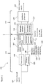
- the system 100 is shown with an 'analysis' part 121 and a 'synthesis' part 131.
- the 'analysis' part 121 is the part from receiving the multi-channel loudspeaker signals up to an encoding of the metadata and downmix signal and the 'synthesis' part 131 is the part from a decoding of the encoded metadata and downmix signal to the presentation of the re-generated signal (for example in multi-channel loudspeaker form).
- the multi-channel signals are passed to a downmixer 103 and to an analysis processor 105.
- the downmixer 103 is configured to receive the multi-channel signals and downmix the signals to a determined number of channels and output the downmix signals 104.
- the downmixer 103 may be configured to generate a 2 audio channel downmix of the multi-channel signals.
- the determined number of channels may be any suitable number of channels.
- the downmixer 103 is optional and the multi-channel signals are passed unprocessed to an encoder 107 in the same manner as the downmix signal are in this example.
- the analysis processor 105 is also configured to receive the multi-channel signals and analyse the signals to produce metadata 106 associated with the multi-channel signals and thus associated with the downmix signals 104.
- the analysis processor 105 may be configured to generate the metadata which may comprise, for each time-frequency analysis interval, a direction parameter 108, an energy ratio parameter 110, a coherence parameter 112, and a diffuseness parameter 114.
- the direction, energy ratio and diffuseness parameters may in some embodiments be considered to be spatial audio parameters.
- the spatial audio parameters comprise parameters which aim to characterize the sound-field created by the multi-channel signals (or two or more playback audio signals in general).
- the coherence parameters may be considered to be signal relationship audio parameters which aim to characterize the relationship between the multi-channel signals.
- the parameters generated may differ from frequency band to frequency band.
- band X all of the parameters are generated and transmitted, whereas in band Y only one of the parameters is generated and transmitted, and furthermore in band Z no parameters are generated or transmitted.
- band Z no parameters are generated or transmitted.
- a practical example of this may be that for some frequency bands such as the highest band some of the parameters are not required for perceptual reasons.
- the downmix signals 104 and the metadata 106 may be passed to an encoder 107.
- the received or retrieved data may be received by a decoder/demultiplexer 133.
- the decoder/demultiplexer 133 may demultiplex the encoded streams and pass the audio encoded stream to a downmix extractor 135 which is configured to decode the audio signals to obtain the downmix signals.
- the decoder/demultiplexer 133 may comprise a metadata extractor 137 which is configured to receive the encoded metadata and generate metadata.
- the decoder/demultiplexer 133 can in some embodiments be a computer (running suitable software stored on memory and on at least one processor), or alternatively a specific device utilizing, for example, FPGAs or ASICs.
- the decoded metadata and downmix audio signals may be passed to a synthesis processor 139.
- the system 100 'synthesis' part 131 further shows a synthesis processor 139 configured to receive the downmix and the metadata and re-creates in any suitable format a synthesized spatial audio in the form of multi-channel signals 110 (these may be multichannel loudspeaker format or in some embodiments any suitable output format such as binaural or Ambisonics signals, depending on the use case) based on the downmix signals and the metadata.
- a synthesis processor 139 configured to receive the downmix and the metadata and re-creates in any suitable format a synthesized spatial audio in the form of multi-channel signals 110 (these may be multichannel loudspeaker format or in some embodiments any suitable output format such as binaural or Ambisonics signals, depending on the use case) based on the downmix signals and the metadata.
- system analysis part
- system is configured to generate a downmix of the multi-channel signals as shown in Figure 4 by step 403.
- system is configured to analyse signals to generate metadata such as direction parameters; energy ratio parameters; diffuseness parameters and coherence parameters as shown in Figure 4 by step 405.
- the system is then configured to encode for storage/transmission the downmix signal and metadata as shown in Figure 4 by step 407.
- the system may store/transmit the encoded downmix and metadata as shown in Figure 4 by step 409.
- the system may retrieve/receive the encoded downmix and metadata as shown in Figure 4 by step 411.
- the system (synthesis part) is configured to synthesize an output multi-channel audio signal based on extracted downmix of multi-channel audio signals and metadata with coherence parameters as shown in Figure 4 by step 415.
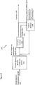
- the analysis processor 105 in some embodiments comprises a time-frequency domain transformer 201.
- the time-frequency domain transformer 201 is configured to receive the multi-channel signals 102 and apply a suitable time to frequency domain transform such as a Short Time Fourier Transform (STFT) in order to convert the input time domain signals into a suitable time-frequency signals.
- STFT Short Time Fourier Transform
- These time-frequency signals may be passed to a direction analyser 203 and to a signal analyser 205.
- the time-frequency signals 202 may be represented in the time-frequency domain representation by s i ( b,n ), where b is the frequency bin index and n is the frame index and i is the channel index.
- n can be considered as a time index with a lower sampling rate than that of the original time-domain signals.
- Each subband k has a lowest bin b k,low and a highest bin b k,high , and the subband contains all bins from b k,low to b k,high .
- the widths of the subbands can approximate any suitable distribution. For example the Equivalent rectangular bandwidth (ERB) scale or the Bark scale.
- the analysis processor 105 comprises a direction analyser 203.
- the direction analyser 203 may be configured to receive the time-frequency signals 202 and based on these signals estimate direction parameters 108.
- the direction parameters may be determined based on any audio based 'direction' determination.
- the direction analyser 203 is configured to estimate the direction with two or more signal inputs. This represents the simplest configuration to estimate a 'direction', more complex processing may be performed with even more signals.
- the direction analyser 203 may thus be configured to provide an azimuth for each frequency band and temporal frame, denoted as azimuth ⁇ ( k,n ) and elevation ⁇ ( k,n ).
- the direction parameter 108 may be also be passed to a signal analyser 205
- the direction analyser 203 is configured to determine an energy ratio parameter 110.
- the energy ratio may be considered to be a determination of the energy of the audio signal which can be considered to arrive from a direction.
- the direct-to-total energy ratio r(k,n) can be estimated, e.g., using a stability measure of the directional estimate, or using any correlation measure, or any other suitable method to obtain a ratio parameter.
- the estimated direction 108 parameters may be output (and passed to an encoder).
- the estimated energy ratio parameters 110 may be passed to a signal analyser 205.
- the analysis processor 105 comprises a signal analyser 205.
- the signal analyser 205 is configured to receive parameters (such as the azimuth ⁇ ( k,n ) and elevation ⁇ (k,n) 108, and the direct-to-total energy ratios r(k, n ) 110) from the direction analyser 203.
- the signal analyser 205 may be further configured to receive the time-frequency signals (s i ( b,n )) 202 from the time-frequency domain transformer 201. All of these are in the time-frequency domain; b is the frequency bin index, k is the frequency band index (each band potentially consists of several bins b), n is the time index, and i is the channel.
- the parameters may be combined over several time indices. Same applies for the frequency axis, as has been expressed, the direction of several frequency bins b could be expressed by one direction parameter in band k consisting of several frequency bins b. The same applies for all of the discussed spatial parameters herein.
- the signal analyser 205 is configured to produce a number of signal parameters. In the following disclosure there are the two parameters: coherence and diffuseness, both analysed in time-frequency domain. In addition, in some embodiments the signal analyser 205 is configured to modify the estimated energy ratios ( r ( k , n )). The signal analyser 205 is configured to generate the coherence and diffuseness parameters based on any suitable known method.
- the first operation is one of receiving time domain multichannel (loudspeaker) audio signals as shown in Figure 5 by step 501.
- time domain to frequency domain transform e.g. STFT
- step 507 applying analysis to determine coherence parameters (such as surrounding and/or spread coherence parameters) and diffuseness parameters is shown in Figure 5 by step 507.
- the energy ratio may also be modified based on the determined coherence parameters in this step.
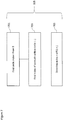
- FIG. 3a an example metadata encoder and specifically the direction metadata encoder 300 is shown according to some embodiments.
- the direction metadata encoder 300 in some embodiments comprises a quantization input 302.
- the quantization input which may also be known as an encoding input is configured to define the granularity of spheres arranged around a reference location or position from which the direction parameter is determined.
- the quantization input is a predefined or fixed value.
- the direction metadata encoder 300 in some embodiments comprises a sphere positioner 303.
- the sphere positioner is configured to configure the arrangement of spheres based on the quantization input value.
- the proposed spherical grid uses the idea of covering a sphere with smaller spheres and considering the centres of the smaller spheres as points defining a grid of almost equidistant directions.
- the concept as shown herein is one in which a sphere is defined relative to the reference location.
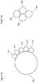
- the sphere can be visualised as a series of circles (or intersections) and for each circle intersection there are located at the circumference of the circle a defined number of (smaller) spheres. This is shown for example with respect to Figure 3c to 3e .
- Figure 3c shows an example 'equatorial cross-section' or a first main circle 370 which has a radius defined as the 'main sphere radius.
- each smaller sphere has a circumference which at one point touches the main sphere circumference and at least one further point which touches at least one further smaller sphere circumference.
- the smaller sphere 371 touches main sphere 370 and smaller sphere 373
- smaller sphere 373 touches main sphere 370 and smaller spheres 371 and 375
- smaller sphere 375 touches main sphere 370 and smaller spheres 373 and 377
- smaller sphere 377 touches main sphere 370 and smaller spheres 375 and 379
- smaller sphere 379 touches main sphere 370 and smaller sphere 377.
- Figure 3d shows an example 'tropical cross-section' or further main circle 380 and the smaller spheres (shown as circle cross-sections) 381, 383, 385 located such that each smaller sphere has a circumference which at one point touches the main sphere (circle) circumference and at least one further point which touches at least one further smaller sphere circumference.
- the smaller sphere 381 touches main sphere 380 and smaller sphere 383, smaller sphere 383 touches main sphere 380 and smaller spheres 381 and 385, smaller sphere 385 touches main sphere 380 and smaller sphere 383.
- Figure 3e shows an example sphere and the cross sections 370, 380 and smaller spheres (cross-sections) 371 associated with cross-section 370, smaller sphere 381 associated with cross-section 380 and other smaller spheres 392, 393, 394, 395, 397, 398.
- the circles with starting azimuth value at 0 are drawn.
- k 4
- [VA(1][GS2]the elevation resolution is approximately 1 degree.
- the resolution is correspondingly smaller.
- Each direction point on one circle can be indexed in increasing order with respect to the azimuth value.
- the index of the first point in each circle is given by an offset that can be deduced from the number of points on each circle, n ( i ).
- the offsets are calculated as the cumulated number of points on the circles for the given order, starting with the value 0 as first offset.
- the direction metadata encoder 300 in some embodiments comprises a direction parameter input 108.
- elevation-azimuth to direction index (EA-DI) converter 305 is configured to perform this conversion according to the following algorithm:
- the granularity, p along the elevation is known.
- the values ⁇ , ⁇ are from a discrete set of values, corresponding to the indexed directions.
- the number of point on each circle and the corresponding offset, off (i) are known.
- the direction index I d 306 may be output.
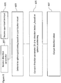
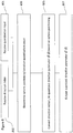
- the receiving of the quantization input is shown in Figure 6 by step 601.
- the method may determine sphere positioning based on the quantization input as shown in Figure 6 by step 603.
- the method may comprise receiving the direction parameter as shown in Figure 6 by step 602.
- the method may comprise converting the direction parameter to a direction index based on the sphere positioning information as shown in Figure 6 by step 605.
- the method may then output the direction index as shown in Figure 6 by step 607.
- the direction is then determined by adding the value of the index of the azimuth to the offset associated with the circle index as shown in Figure 7 by step 705.
- an example metadata extractor 137 and specifically a direction metadata extractor 350 is shown according to some embodiments.
- the direction metadata extractor 350 in some embodiments comprises a quantization input 352. This in some embodiments is passed from the metadata encoder or is otherwise agreed with the encoder.
- the quantization input is configured to define the granularity of spheres arranged around a reference location or position.
- the direction metadata extractor 350 in some embodiments comprises a direction index input 351. This may be received from the encoder or retrieved by any suitable means.
- the direction metadata extractor 350 in some embodiments comprises a sphere positioner 353.
- the sphere positioner 353 is configured to receive as an input the quantization input and generate the sphere arrangement in the same manner as generated in the encoder.
- the quantization input and the sphere positioner 353 is optional and the arrangement of spheres information is passed from the encoder rather than being generated in the extractor.
- the direction metadata extractor 350 comprises a direction index to elevation-azimuth (DI-EA) converter 355.
- the direction index to elevation-azimuth converter 355 is configured to receive the direction index and furthermore the sphere position information and generate an approximate or quantized elevation-azimuth output. In some embodiments the conversion is performed according to the following algorithm. Input: I d Output: ( ⁇ , ⁇ )
- the method may determine sphere positioning based on the quantization input as shown in Figure 8 by step 803.
- the method may comprise receiving the direction index as shown in Figure 8 by step 802.
- the method may then output the quantized direction parameter as shown in Figure 8 by step 807.
- FIG. 9 an example method for converting the direction index to a quantized elevation-azimuth (DI-EA) parameter, as shown in Figure 8 by step 805, according to some embodiments is shown.
- DI-EA quantized elevation-azimuth
- the method comprises finding the circle index value i such that off ( i ) ⁇ I d ⁇ off (i + 1) as shown in Figure 9 by step 901.
- next operation is to calculate the circle index in the hemisphere from the sphere positioning information as shown in Figure 9 by step 903.
- a quantized elevation is determined based on the circle index as shown in Figure 9 by step 905.
- the quantized azimuth is determined based on the circle index and elevation information as shown in Figure 9 by step 907.
- spatial audio processing takes place in frequency bands.
- Those bands could be for example, the frequency bins of the time-frequency transform, or frequency bands combining several bins.
- the combination could be such that approximates properties of human hearing, such as the Bark frequency resolution.
- we could measure and process the audio in time-frequency areas combining several of the frequency bins b and/or time indices n. For simplicity, these aspects were not expressed by all of the equations above.
- typically one set of parameters such as one direction is estimated for that time-frequency area, and all time-frequency samples within that area are synthesized according to that set of parameters, such as that one direction parameter.
- the device 1400 comprises a memory 1411.
- the at least one processor 1407 is coupled to the memory 1411.
- the memory 1411 can be any suitable storage means.
- the memory 1411 comprises a program code section for storing program codes implementable upon the processor 1407.
- the memory 1411 can further comprise a stored data section for storing data, for example data that has been processed or to be processed in accordance with the embodiments as described herein. The implemented program code stored within the program code section and the data stored within the stored data section can be retrieved by the processor 1407 whenever needed via the memory-processor coupling.
- the transceiver can communicate with further apparatus by any suitable known communications protocol.
- the transceiver or transceiver means can use a suitable universal mobile telecommunications system (UMTS) protocol, a wireless local area network (WLAN) protocol such as for example IEEE 802.X, a suitable short-range radio frequency communication protocol such as Bluetooth, or infrared data communication pathway (IRDA).
- UMTS universal mobile telecommunications system
- WLAN wireless local area network
- IRDA infrared data communication pathway
- the transceiver input/output port 1409 may be configured to receive the signals and in some embodiments determine the parameters as described herein by using the processor 1407 executing suitable code. Furthermore the device may generate a suitable downmix signal and parameter output to be transmitted to the synthesis device.
- the device 1400 may be employed as at least part of the synthesis device.
- the input/output port 1409 may be configured to receive the downmix signals and in some embodiments the parameters determined at the capture device or processing device as described herein, and generate a suitable audio signal format output by using the processor 1407 executing suitable code.
- the input/output port 1409 may be coupled to any suitable audio output for example to a multichannel speaker system and/or headphones or similar.
- the various embodiments of the invention may be implemented in hardware or special purpose circuits, software, logic or any combination thereof.
- some aspects may be implemented in hardware, while other aspects may be implemented in firmware or software which may be executed by a controller, microprocessor or other computing device, although the invention is not limited thereto.
- firmware or software which may be executed by a controller, microprocessor or other computing device, although the invention is not limited thereto.
- While various aspects of the invention may be illustrated and described as block diagrams, flow charts, or using some other pictorial representation, it is well understood that these blocks, apparatus, systems, techniques or methods described herein may be implemented in, as non-limiting examples, hardware, software, firmware, special purpose circuits or logic, general purpose hardware or controller or other computing devices, or some combination thereof.
- the embodiments of this invention may be implemented by computer software executable by a data processor of the mobile device, such as in the processor entity, or by hardware, or by a combination of software and hardware.
- any blocks of the logic flow as in the Figures may represent program steps, or interconnected logic circuits, blocks and functions, or a combination of program steps and logic circuits, blocks and functions.
- the software may be stored on such physical media as memory chips, or memory blocks implemented within the processor, magnetic media such as hard disk or floppy disks, and optical media such as for example DVD and the data variants thereof, CD.
- the memory may be of any type suitable to the local technical environment and may be implemented using any suitable data storage technology, such as semiconductor-based memory devices, magnetic memory devices and systems, optical memory devices and systems, fixed memory and removable memory.
- the data processors may be of any type suitable to the local technical environment, and may include one or more of general purpose computers, special purpose computers, microprocessors, digital signal processors (DSPs), application specific integrated circuits (ASIC), gate level circuits and processors based on multi-core processor architecture, as non-limiting examples.
- Embodiments of the inventions may be practiced in various components such as integrated circuit modules.
- the design of integrated circuits is by and large a highly automated process.
- Complex and powerful software tools are available for converting a logic level design into a semiconductor circuit design ready to be etched and formed on a semiconductor substrate.
- Programs such as those provided by Synopsys, Inc. of Mountain View, California and Cadence Design, of San Jose, California automatically route conductors and locate components on a semiconductor chip using well established rules of design as well as libraries of pre-stored design modules.
- the resultant design in a standardized electronic format (e.g., Opus, GDSII, or the like) may be transmitted to a semiconductor fabrication facility or "fab" for fabrication.
Landscapes
- Engineering & Computer Science (AREA)
- Physics & Mathematics (AREA)
- Acoustics & Sound (AREA)
- Signal Processing (AREA)
- Mathematical Physics (AREA)
- Multimedia (AREA)
- Audiology, Speech & Language Pathology (AREA)
- Human Computer Interaction (AREA)
- Computational Linguistics (AREA)
- Health & Medical Sciences (AREA)
- Spectroscopy & Molecular Physics (AREA)
- Algebra (AREA)
- General Physics & Mathematics (AREA)
- Mathematical Analysis (AREA)
- Mathematical Optimization (AREA)
- Pure & Applied Mathematics (AREA)
- Theoretical Computer Science (AREA)
- Stereophonic System (AREA)
Claims (16)
- Appareil pour le codage de signaux audio spatiaux, l'appareil comprenant :un moyen pour déterminer, pour deux signaux audio ou plus, au moins un paramètre audio spatial pour fournir une reproduction audio spatiale, le au moins un paramètre audio spatial comprenant un paramètre de direction avec une composante d'élévation et une composante d'azimut ;un moyen pour définir une grille sphérique générée en couvrant une sphère avec des sphères plus petites, dans lequel les sphères plus petites sont chacune plus petites que la sphère, et dans lequel les centres des sphères plus petites définissent des points de la grille sphérique ; etun moyen pour convertir la composante d'élévation et la composante d'azimut du paramètre de direction en une valeur d'indice sur la base de la grille sphérique définie.
- Appareil selon la revendication 1, dans lequel le moyen pour définir une grille sphérique générée en couvrant une sphère avec des sphères plus petites comprend :un moyen pour sélectionner de nombreuses sphères plus petites déterminées pour un premier cercle de section transversale de la sphère, dans lequel le premier cercle de section transversale est défini par un diamètre de la sphère ; etun moyen pour déterminer de nombreux cercles supplémentaires de section transversale de la sphère, et sélectionner, pour chacun des nombreux cercles supplémentaires de section transversale, de nombreuses sphères supplémentaires des sphères plus petites.
- Appareil selon la revendication 2, dans lequel le premier cercle de section transversale défini par le diamètre de la sphère est l'un parmi :un équateur de la sphère ;tout cercle ayant le même centre que la sphère et étant situé sur la surface de sphère ; etun méridien de la sphère.
- Appareil selon l'une quelconque des revendications 2 et 3, dans lequel le moyen pour définir une grille sphérique générée en couvrant une sphère avec des sphères plus petites comprend un moyen pour définir un ordre d'indice de cercle associé au premier cercle de section transversale et aux nombreux cercles supplémentaires de section transversale.
- Appareil selon l'une quelconque des revendications 2 à 4, dans lequel l'espacement des sphères plus petites sur la sphère est approximativement équidistant par rapport aux sphères plus petites.
- Appareil selon l'une quelconque des revendications 2 à 5, dans lequel les nombreuses sphères plus petites déterminées pour un premier cercle de section transversale de la sphère et les nombreuses sphères plus petites supplémentaires sont déterminées sur la base d'une valeur de quantification d'entrée.
- Appareil selon l'une quelconque des revendications 1 à 6, dans lequel le moyen pour convertir la composante d'élévation et la composante d'azimut du paramètre de direction en la valeur d'indice sur la base de la grille sphérique définie comprend en outre :un moyen pour déterminer une valeur d'indice de cercle de section transversale sur la base d'un ordre défini de la composante d'élévation du paramètre de direction ;un moyen pour déterminer une valeur d'indice intra-cercle sur la base de la composante d'azimut du paramètre de direction ; etla génération de la valeur d'indice sur la base d'une combinaison de la valeur d'indice intra-cercle et d'une valeur de décalage sur la base de la valeur d'indice de cercle de section transversale.
- Appareil pour le décodage de signaux audio spatiaux, l'appareil comprenant :un moyen pour déterminer au moins un indice de direction associé à deux signaux audio ou plus pour fournir une reproduction audio spatiale, le au moins un indice de direction représentant un paramètre spatial avec une composante d'élévation et une composante d'azimut ;un moyen pour déterminer une grille sphérique générée en couvrant une sphère avec des sphères plus petites, dans lequel les sphères plus petites sont chacune plus petites que la sphère, et dans lequel les centres des sphères plus petites définissent des points de la grille sphérique ;un moyen pour convertir le au moins un indice de direction en une représentation quantifiée d'élévation et une représentation quantifiée d'azimut de la composante d'élévation et de la composante d'azimut du paramètre de direction, en une valeur d'indice sur la base de la grille sphérique déterminée ; etun moyen pour convertir la représentation quantifiée d'élévation et la représentation quantifiée d'azimut de la composante d'élévation et de la composante d'azimut du paramètre de direction en une valeur d'indice sur la base de la grille sphérique déterminée.
- Appareil selon la revendication 8, dans lequel le moyen pour déterminer une grille sphérique générée en couvrant une sphère avec des sphères plus petites comprend en outre :un moyen pour sélectionner de nombreuses sphères plus petites déterminées pour un premier cercle de section transversale de la sphère, dans lequel le premier cercle de section transversale est défini par un diamètre de la sphère ; etun moyen pour déterminer de nombreux cercles supplémentaires de section transversale de la sphère et sélectionner pour chacun des nombreux cercles supplémentaires de section transversale de nombreuses sphères supplémentaires des sphères plus petites.
- Appareil selon la revendication 9, dans lequel le premier cercle de section transversale défini par le diamètre de la sphère est l'un parmi :un équateur de la sphère ;tout cercle ayant le même centre que la sphère, et étant situé sur la surface de sphère ; etun méridien de la sphère.
- Appareil selon l'une quelconque des revendications 9 et 10, dans lequel le moyen pour définir une grille sphérique générée en couvrant une sphère avec des sphères plus petites comprend un moyen pour définir un ordre d'indice de cercle associé au premier cercle de section transversale et aux nombreux cercles supplémentaires de section transversale.
- Appareil selon l'une quelconque des revendications 9 à 11, dans lequel l'espacement des sphères plus petites sur la sphère est approximativement équidistant par rapport aux sphères plus petites.
- Appareil selon l'une quelconque des revendications 9 à 12, dans lequel les nombreuses sphères plus petites déterminées pour un premier cercle de section transversale de la sphère et les nombreuses sphères plus petites supplémentaires sont déterminées sur la base d'une valeur de quantification d'entrée.
- Appareil selon l'une quelconque des revendications 8 à 13, dans lequel le moyen pour convertir la représentation quantifiée d'élévation et la représentation quantifiée d'azimut de la composante d'élévation et de la composante d'azimut du paramètre de direction en la valeur d'indice sur la base de la grille sphérique déterminée comprend en outre :un moyen pour déterminer une valeur d'indice de cercle de section transversale sur la base de la valeur d'indice ;un moyen pour déterminer la représentation quantifiée d'élévation de la composante d'élévation sur la base de la valeur d'indice de cercle de section transversale ; etun moyen pour générer la représentation quantifiée d'azimut de la composante d'azimut sur la base d'une valeur d'indice de reste après avoir retiré, de la valeur d'indice, un décalage associé à la valeur d'indice de cercle de section transversale.
- Procédé pour le codage de signaux audio spatiaux, le procédé comprenant :la détermination, pour deux signaux audio ou plus, d'au moins un paramètre audio spatial pour fournir une reproduction audio spatiale, le au moins un paramètre audio spatial comprenant un paramètre de direction avec une composante d'élévation et une composante d'azimut ;la définition d'une grille sphérique générée en couvrant une sphère avec des sphères plus petites, dans lequel les sphères plus petites sont chacune plus petites que la sphère, et dans lequel les centres des sphères plus petites définissent des points de la grille sphérique ; etla conversion de la composante d'élévation et de la composante d'azimut du paramètre de direction en une valeur d'indice sur la base de la grille sphérique définie.
- Procédé pour le décodage de signaux audio spatiaux, le procédé comprenant :la détermination du au moins un indice de direction associé à deux signaux audio ou plus pour fournir une reproduction audio spatiale, le au moins un indice de direction représentant un paramètre spatial avec une composante d'élévation et une composante d'azimut ;la détermination d'une grille sphérique générée en couvrant une sphère avec des sphères plus petites, dans lequel les sphères plus petites sont chacune plus petites que la sphère, et dans lequel les centres des sphères plus petites définissent des points de la grille sphérique ; etla conversion du au moins un indice de direction en une représentation quantifiée d'élévation et une représentation quantifiée d'azimut de la composante d'élévation et de la composante d'azimut du paramètre de direction ; etla conversion de la représentation quantifiée d'élévation et la représentation quantifiée d'azimut de la composante d'élévation et de la composante d'azimut du paramètre de direction en une valeur d'indice sur la base de la grille sphérique déterminée.
Priority Applications (1)
| Application Number | Priority Date | Filing Date | Title |
|---|---|---|---|
| PL17800810T PL3707706T3 (pl) | 2017-11-10 | 2017-11-10 | Określanie kodowania przestrzennego parametrów dźwięku i związane z tym dekodowanie |
Applications Claiming Priority (1)
| Application Number | Priority Date | Filing Date | Title |
|---|---|---|---|
| PCT/EP2017/078948 WO2019091575A1 (fr) | 2017-11-10 | 2017-11-10 | Détermination d'un codage de paramètre audio spatial et décodage associé |
Publications (2)
| Publication Number | Publication Date |
|---|---|
| EP3707706A1 EP3707706A1 (fr) | 2020-09-16 |
| EP3707706B1 true EP3707706B1 (fr) | 2021-08-04 |
Family
ID=60388041
Family Applications (1)
| Application Number | Title | Priority Date | Filing Date |
|---|---|---|---|
| EP17800810.8A Active EP3707706B1 (fr) | 2017-11-10 | 2017-11-10 | Détermination d'un codage de paramètre audio spatial et décodage associé |
Country Status (5)
| Country | Link |
|---|---|
| US (1) | US11328735B2 (fr) |
| EP (1) | EP3707706B1 (fr) |
| CN (1) | CN111316353B (fr) |
| PL (1) | PL3707706T3 (fr) |
| WO (1) | WO2019091575A1 (fr) |
Families Citing this family (14)
| Publication number | Priority date | Publication date | Assignee | Title |
|---|---|---|---|---|
| US11062716B2 (en) | 2017-12-28 | 2021-07-13 | Nokia Technologies Oy | Determination of spatial audio parameter encoding and associated decoding |
| GB2572761A (en) * | 2018-04-09 | 2019-10-16 | Nokia Technologies Oy | Quantization of spatial audio parameters |
| GB2577698A (en) | 2018-10-02 | 2020-04-08 | Nokia Technologies Oy | Selection of quantisation schemes for spatial audio parameter encoding |
| EP4462821A3 (fr) | 2018-11-13 | 2024-12-25 | Dolby Laboratories Licensing Corporation | Représentation d'audio spatial au moyen d'un signal audio et métadonnées associées |
| EP3881559B1 (fr) | 2018-11-13 | 2024-02-14 | Dolby Laboratories Licensing Corporation | Traitement audio dans des services audio immersifs |
| GB2585187A (en) * | 2019-06-25 | 2021-01-06 | Nokia Technologies Oy | Determination of spatial audio parameter encoding and associated decoding |
| GB2587196A (en) | 2019-09-13 | 2021-03-24 | Nokia Technologies Oy | Determination of spatial audio parameter encoding and associated decoding |
| WO2021053266A2 (fr) | 2019-09-17 | 2021-03-25 | Nokia Technologies Oy | Codage de paramètres audio spatiaux et décodage associé |
| GB2592896A (en) * | 2020-01-13 | 2021-09-15 | Nokia Technologies Oy | Spatial audio parameter encoding and associated decoding |
| GB202014572D0 (en) * | 2020-09-16 | 2020-10-28 | Nokia Technologies Oy | Spatial audio parameter encoding and associated decoding |
| KR20230133341A (ko) | 2021-01-18 | 2023-09-19 | 노키아 테크놀로지스 오와이 | 공간 오디오 파라미터들의 변환 |
| CN113889125B (zh) * | 2021-12-02 | 2022-03-04 | 腾讯科技(深圳)有限公司 | 音频生成方法、装置、计算机设备和存储介质 |
| GB2615607A (en) | 2022-02-15 | 2023-08-16 | Nokia Technologies Oy | Parametric spatial audio rendering |
| JP2025510730A (ja) | 2022-03-22 | 2025-04-15 | ノキア テクノロジーズ オサケユイチア | パラメトリック空間オーディオエンコーディング |
Family Cites Families (15)
| Publication number | Priority date | Publication date | Assignee | Title |
|---|---|---|---|---|
| EP1500084B1 (fr) * | 2002-04-22 | 2008-01-23 | Koninklijke Philips Electronics N.V. | Representation parametrique d'un signal audio spatial |
| ES2282899T3 (es) * | 2003-10-30 | 2007-10-16 | Koninklijke Philips Electronics N.V. | Codificacion o descodificacion de señales de audio. |
| ATE390683T1 (de) * | 2004-03-01 | 2008-04-15 | Dolby Lab Licensing Corp | Mehrkanalige audiocodierung |
| GB2467247B (en) * | 2007-10-04 | 2012-02-29 | Creative Tech Ltd | Phase-amplitude 3-D stereo encoder and decoder |
| EP2249334A1 (fr) * | 2009-05-08 | 2010-11-10 | Fraunhofer-Gesellschaft zur Förderung der angewandten Forschung e.V. | Transcodeur de format audio |
| JP2014506416A (ja) * | 2010-12-22 | 2014-03-13 | ジェノーディオ,インコーポレーテッド | オーディオ空間化および環境シミュレーション |
| EP2839460A4 (fr) * | 2012-04-18 | 2015-12-30 | Nokia Technologies Oy | Codeur de signal audio stéréo |
| US20140086416A1 (en) * | 2012-07-15 | 2014-03-27 | Qualcomm Incorporated | Systems, methods, apparatus, and computer-readable media for three-dimensional audio coding using basis function coefficients |
| KR102429953B1 (ko) * | 2012-07-19 | 2022-08-08 | 돌비 인터네셔널 에이비 | 다채널 오디오 신호들의 렌더링을 향상시키기 위한 방법 및 디바이스 |
| US9384741B2 (en) * | 2013-05-29 | 2016-07-05 | Qualcomm Incorporated | Binauralization of rotated higher order ambisonics |
| US9466305B2 (en) * | 2013-05-29 | 2016-10-11 | Qualcomm Incorporated | Performing positional analysis to code spherical harmonic coefficients |
| TWI579831B (zh) * | 2013-09-12 | 2017-04-21 | 杜比國際公司 | 用於參數量化的方法、用於量化的參數之解量化方法及其電腦可讀取的媒體、音頻編碼器、音頻解碼器及音頻系統 |
| US20150332682A1 (en) * | 2014-05-16 | 2015-11-19 | Qualcomm Incorporated | Spatial relation coding for higher order ambisonic coefficients |
| US9800990B1 (en) * | 2016-06-10 | 2017-10-24 | C Matter Limited | Selecting a location to localize binaural sound |
| EP3618466B1 (fr) * | 2018-08-29 | 2024-02-21 | Dolby Laboratories Licensing Corporation | Génération de flux audio binaural extensible |
-
2017
- 2017-11-10 PL PL17800810T patent/PL3707706T3/pl unknown
- 2017-11-10 US US16/762,389 patent/US11328735B2/en active Active
- 2017-11-10 EP EP17800810.8A patent/EP3707706B1/fr active Active
- 2017-11-10 CN CN201780096600.4A patent/CN111316353B/zh active Active
- 2017-11-10 WO PCT/EP2017/078948 patent/WO2019091575A1/fr not_active Ceased
Also Published As
| Publication number | Publication date |
|---|---|
| WO2019091575A1 (fr) | 2019-05-16 |
| CN111316353B (zh) | 2023-11-17 |
| US11328735B2 (en) | 2022-05-10 |
| CN111316353A (zh) | 2020-06-19 |
| PL3707706T3 (pl) | 2021-11-22 |
| US20200273467A1 (en) | 2020-08-27 |
| EP3707706A1 (fr) | 2020-09-16 |
Similar Documents
| Publication | Publication Date | Title |
|---|---|---|
| EP3707706B1 (fr) | Détermination d'un codage de paramètre audio spatial et décodage associé | |
| EP3732678B1 (fr) | Détermination de codage de paramètre audio spatial et décodage associé | |
| EP3818525B1 (fr) | Détermination d'un codage de paramètre audio spatial et d'un décodage associé | |
| JP7405962B2 (ja) | 空間オーディオパラメータ符号化および関連する復号化の決定 | |
| EP3874492B1 (fr) | Détermination du codage de paramètre audio spatial et décodage associé | |
| EP3776545B1 (fr) | Quantification de paramètres audio spatiaux | |
| EP4014235B1 (fr) | Quantification de paramètres de direction de l'audio spatial | |
| US20220366918A1 (en) | Spatial audio parameter encoding and associated decoding | |
| WO2020016479A1 (fr) | Quantification éparse de paramètres audio spatiaux | |
| EP3991170A1 (fr) | Détermination de codage de paramètre audio spatial et décodage associé | |
| US20250029620A1 (en) | Spatial audio parameter decoding | |
| US12412585B2 (en) | Transforming spatial audio parameters |
Legal Events
| Date | Code | Title | Description |
|---|---|---|---|
| STAA | Information on the status of an ep patent application or granted ep patent |
Free format text: STATUS: UNKNOWN |
|
| STAA | Information on the status of an ep patent application or granted ep patent |
Free format text: STATUS: THE INTERNATIONAL PUBLICATION HAS BEEN MADE |
|
| PUAI | Public reference made under article 153(3) epc to a published international application that has entered the european phase |
Free format text: ORIGINAL CODE: 0009012 |
|
| STAA | Information on the status of an ep patent application or granted ep patent |
Free format text: STATUS: REQUEST FOR EXAMINATION WAS MADE |
|
| 17P | Request for examination filed |
Effective date: 20200610 |
|
| AK | Designated contracting states |
Kind code of ref document: A1 Designated state(s): AL AT BE BG CH CY CZ DE DK EE ES FI FR GB GR HR HU IE IS IT LI LT LU LV MC MK MT NL NO PL PT RO RS SE SI SK SM TR |
|
| AX | Request for extension of the european patent |
Extension state: BA ME |
|
| DAV | Request for validation of the european patent (deleted) | ||
| DAX | Request for extension of the european patent (deleted) | ||
| GRAP | Despatch of communication of intention to grant a patent |
Free format text: ORIGINAL CODE: EPIDOSNIGR1 |
|
| STAA | Information on the status of an ep patent application or granted ep patent |
Free format text: STATUS: GRANT OF PATENT IS INTENDED |
|
| INTG | Intention to grant announced |
Effective date: 20210408 |
|
| GRAS | Grant fee paid |
Free format text: ORIGINAL CODE: EPIDOSNIGR3 |
|
| GRAA | (expected) grant |
Free format text: ORIGINAL CODE: 0009210 |
|
| STAA | Information on the status of an ep patent application or granted ep patent |
Free format text: STATUS: THE PATENT HAS BEEN GRANTED |
|
| AK | Designated contracting states |
Kind code of ref document: B1 Designated state(s): AL AT BE BG CH CY CZ DE DK EE ES FI FR GB GR HR HU IE IS IT LI LT LU LV MC MK MT NL NO PL PT RO RS SE SI SK SM TR |
|
| REG | Reference to a national code |
Ref country code: GB Ref legal event code: FG4D |
|
| REG | Reference to a national code |
Ref country code: AT Ref legal event code: REF Ref document number: 1417816 Country of ref document: AT Kind code of ref document: T Effective date: 20210815 |
|
| REG | Reference to a national code |
Ref country code: CH Ref legal event code: EP |
|
| REG | Reference to a national code |
Ref country code: NL Ref legal event code: FP |
|
| REG | Reference to a national code |
Ref country code: DE Ref legal event code: R096 Ref document number: 602017043466 Country of ref document: DE |
|
| REG | Reference to a national code |
Ref country code: IE Ref legal event code: FG4D |
|
| REG | Reference to a national code |
Ref country code: SE Ref legal event code: TRGR |
|
| REG | Reference to a national code |
Ref country code: LT Ref legal event code: MG9D |
|
| REG | Reference to a national code |
Ref country code: AT Ref legal event code: MK05 Ref document number: 1417816 Country of ref document: AT Kind code of ref document: T Effective date: 20210804 |
|
| PG25 | Lapsed in a contracting state [announced via postgrant information from national office to epo] |
Ref country code: RS Free format text: LAPSE BECAUSE OF FAILURE TO SUBMIT A TRANSLATION OF THE DESCRIPTION OR TO PAY THE FEE WITHIN THE PRESCRIBED TIME-LIMIT Effective date: 20210804 Ref country code: HR Free format text: LAPSE BECAUSE OF FAILURE TO SUBMIT A TRANSLATION OF THE DESCRIPTION OR TO PAY THE FEE WITHIN THE PRESCRIBED TIME-LIMIT Effective date: 20210804 Ref country code: ES Free format text: LAPSE BECAUSE OF FAILURE TO SUBMIT A TRANSLATION OF THE DESCRIPTION OR TO PAY THE FEE WITHIN THE PRESCRIBED TIME-LIMIT Effective date: 20210804 Ref country code: FI Free format text: LAPSE BECAUSE OF FAILURE TO SUBMIT A TRANSLATION OF THE DESCRIPTION OR TO PAY THE FEE WITHIN THE PRESCRIBED TIME-LIMIT Effective date: 20210804 Ref country code: BG Free format text: LAPSE BECAUSE OF FAILURE TO SUBMIT A TRANSLATION OF THE DESCRIPTION OR TO PAY THE FEE WITHIN THE PRESCRIBED TIME-LIMIT Effective date: 20211104 Ref country code: AT Free format text: LAPSE BECAUSE OF FAILURE TO SUBMIT A TRANSLATION OF THE DESCRIPTION OR TO PAY THE FEE WITHIN THE PRESCRIBED TIME-LIMIT Effective date: 20210804 Ref country code: LT Free format text: LAPSE BECAUSE OF FAILURE TO SUBMIT A TRANSLATION OF THE DESCRIPTION OR TO PAY THE FEE WITHIN THE PRESCRIBED TIME-LIMIT Effective date: 20210804 Ref country code: PT Free format text: LAPSE BECAUSE OF FAILURE TO SUBMIT A TRANSLATION OF THE DESCRIPTION OR TO PAY THE FEE WITHIN THE PRESCRIBED TIME-LIMIT Effective date: 20211206 Ref country code: NO Free format text: LAPSE BECAUSE OF FAILURE TO SUBMIT A TRANSLATION OF THE DESCRIPTION OR TO PAY THE FEE WITHIN THE PRESCRIBED TIME-LIMIT Effective date: 20211104 |
|
| PG25 | Lapsed in a contracting state [announced via postgrant information from national office to epo] |
Ref country code: LV Free format text: LAPSE BECAUSE OF FAILURE TO SUBMIT A TRANSLATION OF THE DESCRIPTION OR TO PAY THE FEE WITHIN THE PRESCRIBED TIME-LIMIT Effective date: 20210804 Ref country code: GR Free format text: LAPSE BECAUSE OF FAILURE TO SUBMIT A TRANSLATION OF THE DESCRIPTION OR TO PAY THE FEE WITHIN THE PRESCRIBED TIME-LIMIT Effective date: 20211105 |
|
| PG25 | Lapsed in a contracting state [announced via postgrant information from national office to epo] |
Ref country code: DK Free format text: LAPSE BECAUSE OF FAILURE TO SUBMIT A TRANSLATION OF THE DESCRIPTION OR TO PAY THE FEE WITHIN THE PRESCRIBED TIME-LIMIT Effective date: 20210804 |
|
| REG | Reference to a national code |
Ref country code: DE Ref legal event code: R097 Ref document number: 602017043466 Country of ref document: DE |
|
| PG25 | Lapsed in a contracting state [announced via postgrant information from national office to epo] |
Ref country code: SM Free format text: LAPSE BECAUSE OF FAILURE TO SUBMIT A TRANSLATION OF THE DESCRIPTION OR TO PAY THE FEE WITHIN THE PRESCRIBED TIME-LIMIT Effective date: 20210804 Ref country code: SK Free format text: LAPSE BECAUSE OF FAILURE TO SUBMIT A TRANSLATION OF THE DESCRIPTION OR TO PAY THE FEE WITHIN THE PRESCRIBED TIME-LIMIT Effective date: 20210804 Ref country code: RO Free format text: LAPSE BECAUSE OF FAILURE TO SUBMIT A TRANSLATION OF THE DESCRIPTION OR TO PAY THE FEE WITHIN THE PRESCRIBED TIME-LIMIT Effective date: 20210804 Ref country code: EE Free format text: LAPSE BECAUSE OF FAILURE TO SUBMIT A TRANSLATION OF THE DESCRIPTION OR TO PAY THE FEE WITHIN THE PRESCRIBED TIME-LIMIT Effective date: 20210804 Ref country code: CZ Free format text: LAPSE BECAUSE OF FAILURE TO SUBMIT A TRANSLATION OF THE DESCRIPTION OR TO PAY THE FEE WITHIN THE PRESCRIBED TIME-LIMIT Effective date: 20210804 Ref country code: AL Free format text: LAPSE BECAUSE OF FAILURE TO SUBMIT A TRANSLATION OF THE DESCRIPTION OR TO PAY THE FEE WITHIN THE PRESCRIBED TIME-LIMIT Effective date: 20210804 |
|
| PLBE | No opposition filed within time limit |
Free format text: ORIGINAL CODE: 0009261 |
|
| STAA | Information on the status of an ep patent application or granted ep patent |
Free format text: STATUS: NO OPPOSITION FILED WITHIN TIME LIMIT |
|
| PG25 | Lapsed in a contracting state [announced via postgrant information from national office to epo] |
Ref country code: MC Free format text: LAPSE BECAUSE OF FAILURE TO SUBMIT A TRANSLATION OF THE DESCRIPTION OR TO PAY THE FEE WITHIN THE PRESCRIBED TIME-LIMIT Effective date: 20210804 |
|
| REG | Reference to a national code |
Ref country code: CH Ref legal event code: PL |
|
| 26N | No opposition filed |
Effective date: 20220506 |
|
| PG25 | Lapsed in a contracting state [announced via postgrant information from national office to epo] |
Ref country code: LU Free format text: LAPSE BECAUSE OF NON-PAYMENT OF DUE FEES Effective date: 20211110 Ref country code: BE Free format text: LAPSE BECAUSE OF NON-PAYMENT OF DUE FEES Effective date: 20211130 |
|
| REG | Reference to a national code |
Ref country code: BE Ref legal event code: MM Effective date: 20211130 |
|
| PG25 | Lapsed in a contracting state [announced via postgrant information from national office to epo] |
Ref country code: SI Free format text: LAPSE BECAUSE OF FAILURE TO SUBMIT A TRANSLATION OF THE DESCRIPTION OR TO PAY THE FEE WITHIN THE PRESCRIBED TIME-LIMIT Effective date: 20210804 Ref country code: LI Free format text: LAPSE BECAUSE OF NON-PAYMENT OF DUE FEES Effective date: 20211130 Ref country code: CH Free format text: LAPSE BECAUSE OF NON-PAYMENT OF DUE FEES Effective date: 20211130 |
|
| PG25 | Lapsed in a contracting state [announced via postgrant information from national office to epo] |
Ref country code: IE Free format text: LAPSE BECAUSE OF NON-PAYMENT OF DUE FEES Effective date: 20211110 |
|
| PG25 | Lapsed in a contracting state [announced via postgrant information from national office to epo] |
Ref country code: CY Free format text: LAPSE BECAUSE OF FAILURE TO SUBMIT A TRANSLATION OF THE DESCRIPTION OR TO PAY THE FEE WITHIN THE PRESCRIBED TIME-LIMIT Effective date: 20210804 |
|
| P01 | Opt-out of the competence of the unified patent court (upc) registered |
Effective date: 20230527 |
|
| PG25 | Lapsed in a contracting state [announced via postgrant information from national office to epo] |
Ref country code: HU Free format text: LAPSE BECAUSE OF FAILURE TO SUBMIT A TRANSLATION OF THE DESCRIPTION OR TO PAY THE FEE WITHIN THE PRESCRIBED TIME-LIMIT; INVALID AB INITIO Effective date: 20171110 |
|
| PG25 | Lapsed in a contracting state [announced via postgrant information from national office to epo] |
Ref country code: MK Free format text: LAPSE BECAUSE OF FAILURE TO SUBMIT A TRANSLATION OF THE DESCRIPTION OR TO PAY THE FEE WITHIN THE PRESCRIBED TIME-LIMIT Effective date: 20210804 |
|
| PG25 | Lapsed in a contracting state [announced via postgrant information from national office to epo] |
Ref country code: TR Free format text: LAPSE BECAUSE OF FAILURE TO SUBMIT A TRANSLATION OF THE DESCRIPTION OR TO PAY THE FEE WITHIN THE PRESCRIBED TIME-LIMIT Effective date: 20210804 |
|
| PG25 | Lapsed in a contracting state [announced via postgrant information from national office to epo] |
Ref country code: MT Free format text: LAPSE BECAUSE OF FAILURE TO SUBMIT A TRANSLATION OF THE DESCRIPTION OR TO PAY THE FEE WITHIN THE PRESCRIBED TIME-LIMIT Effective date: 20210804 |
|
| PGFP | Annual fee paid to national office [announced via postgrant information from national office to epo] |
Ref country code: FR Payment date: 20250930 Year of fee payment: 9 |
|
| PGFP | Annual fee paid to national office [announced via postgrant information from national office to epo] |
Ref country code: NL Payment date: 20251003 Year of fee payment: 9 |
|
| PGFP | Annual fee paid to national office [announced via postgrant information from national office to epo] |
Ref country code: DE Payment date: 20250930 Year of fee payment: 9 |
|
| PGFP | Annual fee paid to national office [announced via postgrant information from national office to epo] |
Ref country code: GB Payment date: 20251001 Year of fee payment: 9 |
|
| PGFP | Annual fee paid to national office [announced via postgrant information from national office to epo] |
Ref country code: IT Payment date: 20251022 Year of fee payment: 9 |
|
| PGFP | Annual fee paid to national office [announced via postgrant information from national office to epo] |
Ref country code: SE Payment date: 20251001 Year of fee payment: 9 |
|
| PGFP | Annual fee paid to national office [announced via postgrant information from national office to epo] |
Ref country code: PL Payment date: 20251013 Year of fee payment: 9 |