EP3708004B1 - Four à débit d'air amélioré - Google Patents
Four à débit d'air amélioré Download PDFInfo
- Publication number
- EP3708004B1 EP3708004B1 EP19216056.2A EP19216056A EP3708004B1 EP 3708004 B1 EP3708004 B1 EP 3708004B1 EP 19216056 A EP19216056 A EP 19216056A EP 3708004 B1 EP3708004 B1 EP 3708004B1
- Authority
- EP
- European Patent Office
- Prior art keywords
- oven
- meal
- air
- fan
- carrier
- Prior art date
- Legal status (The legal status is an assumption and is not a legal conclusion. Google has not performed a legal analysis and makes no representation as to the accuracy of the status listed.)
- Active
Links
Images






Classifications
-
- A—HUMAN NECESSITIES
- A47—FURNITURE; DOMESTIC ARTICLES OR APPLIANCES; COFFEE MILLS; SPICE MILLS; SUCTION CLEANERS IN GENERAL
- A47J—KITCHEN EQUIPMENT; COFFEE MILLS; SPICE MILLS; APPARATUS FOR MAKING BEVERAGES
- A47J37/00—Baking; Roasting; Grilling; Frying
- A47J37/06—Roasters; Grills; Sandwich grills
- A47J37/0623—Small-size cooking ovens, i.e. defining an at least partially closed cooking cavity
- A47J37/0629—Small-size cooking ovens, i.e. defining an at least partially closed cooking cavity with electric heating elements
- A47J37/0641—Small-size cooking ovens, i.e. defining an at least partially closed cooking cavity with electric heating elements with forced air circulation, e.g. air fryers
-
- A—HUMAN NECESSITIES
- A21—BAKING; EDIBLE DOUGHS
- A21B—BAKERS' OVENS; MACHINES OR EQUIPMENT FOR BAKING
- A21B1/00—Bakers' ovens
- A21B1/02—Bakers' ovens characterised by the heating arrangements
- A21B1/24—Ovens heated by media flowing therethrough
- A21B1/26—Ovens heated by media flowing therethrough by hot air
-
- A—HUMAN NECESSITIES
- A21—BAKING; EDIBLE DOUGHS
- A21B—BAKERS' OVENS; MACHINES OR EQUIPMENT FOR BAKING
- A21B1/00—Bakers' ovens
- A21B1/50—Bakers' ovens characterised by having removable baking surfaces
-
- A—HUMAN NECESSITIES
- A21—BAKING; EDIBLE DOUGHS
- A21B—BAKERS' OVENS; MACHINES OR EQUIPMENT FOR BAKING
- A21B3/00—Parts or accessories of ovens
- A21B3/15—Baking sheets; Baking boards
-
- B—PERFORMING OPERATIONS; TRANSPORTING
- B64—AIRCRAFT; AVIATION; COSMONAUTICS
- B64D—EQUIPMENT FOR FITTING IN OR TO AIRCRAFT; FLIGHT SUITS; PARACHUTES; ARRANGEMENT OR MOUNTING OF POWER PLANTS OR PROPULSION TRANSMISSIONS IN AIRCRAFT
- B64D11/00—Passenger or crew accommodation; Flight-deck installations not otherwise provided for
- B64D11/04—Galleys
-
- F—MECHANICAL ENGINEERING; LIGHTING; HEATING; WEAPONS; BLASTING
- F24—HEATING; RANGES; VENTILATING
- F24C—DOMESTIC STOVES OR RANGES ; DETAILS OF DOMESTIC STOVES OR RANGES, OF GENERAL APPLICATION
- F24C15/00—Details
- F24C15/16—Shelves, racks or trays inside ovens; Supports therefor
-
- F—MECHANICAL ENGINEERING; LIGHTING; HEATING; WEAPONS; BLASTING
- F24—HEATING; RANGES; VENTILATING
- F24C—DOMESTIC STOVES OR RANGES ; DETAILS OF DOMESTIC STOVES OR RANGES, OF GENERAL APPLICATION
- F24C15/00—Details
- F24C15/32—Arrangements of ducts for hot gases, e.g. in or around baking ovens
- F24C15/322—Arrangements of ducts for hot gases, e.g. in or around baking ovens with forced circulation
-
- F—MECHANICAL ENGINEERING; LIGHTING; HEATING; WEAPONS; BLASTING
- F24—HEATING; RANGES; VENTILATING
- F24C—DOMESTIC STOVES OR RANGES ; DETAILS OF DOMESTIC STOVES OR RANGES, OF GENERAL APPLICATION
- F24C15/00—Details
- F24C15/32—Arrangements of ducts for hot gases, e.g. in or around baking ovens
- F24C15/322—Arrangements of ducts for hot gases, e.g. in or around baking ovens with forced circulation
- F24C15/325—Arrangements of ducts for hot gases, e.g. in or around baking ovens with forced circulation electrically-heated
-
- F—MECHANICAL ENGINEERING; LIGHTING; HEATING; WEAPONS; BLASTING
- F24—HEATING; RANGES; VENTILATING
- F24C—DOMESTIC STOVES OR RANGES ; DETAILS OF DOMESTIC STOVES OR RANGES, OF GENERAL APPLICATION
- F24C15/00—Details
- F24C15/30—Arrangements for mounting stoves or ranges in particular locations
Definitions
- WO 2012/062875 A1 , EP2236942 A1 , and JP S57 115039 each discloses a known oven having a fan for distributing heat in the oven.
- embodiments of the invention disclosed herein are directed to an aircraft galley including such a system.
- a letter following a reference numeral is intended to reference an embodiment of the feature or element that may be similar, but not necessarily identical, to a previously described element or feature bearing the same reference numeral (e.g., 1, 1a, 1b).
- reference numeral e.g. 1, 1a, 1b
- Such shorthand notations are used for purposes of convenience only, and should not be construed to limit the inventive concepts disclosed herein in any way unless expressly stated to the contrary.
- embodiments of the invention disclosed herein are directed to a system comprising an oven with improved airflow within an oven cavity.
- the improved airflow within the oven may reduce unevenness between temperatures of meals on meal trays.
- the inventive system includes at least one fan configured to blow air over heating elements so as to blow heated air first through a meal carrier and then suck the air between the meal carrier and inner oven walls back toward the fans.
- energy of the heated air may be first given to the meals on meal trays of the meal carrier, and then, relatively cooler return air is guided between the meal carrier and the inner oven walls toward the rear of the oven, where at least one fan and the at least one heating element are located.
- the heated air may impart more energy to the meals and less energy to the inner oven walls, as opposed to existing ovens where the heated air may first impart energy to the inner oven walls.
- the oven may have the benefit of having a cooler temperature on the outer oven walls such that less insulation may be required between the inner oven walls and the outer oven walls or such that air conditioning costs can be reduced in a galley.
- Embodiments may include one or more air deflectors and/or a baffle plate configured to direct the heated air evenly over the meals on the meal trays of the meal carrier.
- the fans of the oven may be radial fans, axial fans, tangential fans, or some combination thereof.
- the oven may include separate heating elements for every meal tray so that heat energy may be evenly distributed to the meal trays.
- the aircraft 100 may include one or more galleys 102 including one or more ovens 104.
- the oven 104 may be implemented as an oven insert. While the oven 104 is exemplarily depicted in the aircraft 100, the oven 104 may be implemented in any suitable environment.
- the oven 104 includes inner walls 110 defining a cavity within the oven, wherein the oven has a front and a rear 116.
- the oven 104 may further include outer walls 106, insulation 108, and a door 112 at the front of the oven 104.
- the oven 104 has a front (e.g., near the door 112 of the oven 104), and may further have a bottom 114, a top 118, and two sides (not shown).
- the oven 104 includes a cavity contained within the inner walls 110 of the oven 104.
- a meal carrier 120 is positioned within the cavity of the oven 104.
- the meal carrier 120 includes meal trays 122 configured to hold meals within the oven 104.
- the meal carrier 120 has a top wall 124, a bottom wall 126, and two side walls 134 with openings at the front and rear of the meal carrier to allow heated air to be blown by at least one fan 130 over the meal trays 122.
- the oven 104 includes at least one heating element 128 located near the rear 116 of the oven between the meal carrier 120 and the at least one fan 130.
- the at least one fan 130 is positioned near the rear 116 of the oven 104 between the inner walls 110 and the heating elements 128.
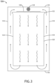
- the oven includes one or more air deflectors 136, and may include a further air deflector 132 and/or a baffle plate 140. As shown in FIG. 5 , the baffle plate 140 may include baffles 138 and baffle plate openings 142.
- the baffle plate 140 may be substituted with a mesh separating the at least one fan 130 and the at least one heating element 128 from the meal carrier 120 to prevent the meal carrier 120 from contacting the at least one fan 130 and/or the at least one heating element 128.
- the oven 104 may be configured to evenly distribute heated air over the meal trays 122.
- the meal carrier 120 is positioned within the cavity of the oven 104.
- the meal carrier 120 has a front and a rear corresponding to the front (e.g., near the door 112) and the rear 116 of the oven 104, respectively.
- the meal carrier 120 includes the top wall 124, the bottom wall 126, and the two side walls 134.
- the front and the rear of the meal carrier 120 are open to allow a flow of air through the meal carrier 120 from the rear 116 of the oven to the front of the oven 104.
- the meal carrier 120 includes the meal trays 122 positioned generally parallel to the top wall 124 and the bottom wall 126 of the meal carrier 120.
- the meal carrier 120 may be implemented as a drawer system (e.g., a fixed drawer system) with the meal trays 122.
- the at least one heating element 128 is configured to heat air in the oven 104.
- the heating elements 128 are positioned between the meal carrier 120 and the rear 116 of the oven 104.
- each of the heating elements 128 may be positioned at a height between heights of two meal trays of the meal trays 122 or at a same height as a height of one of the meal trays 122.
- each meal tray 122 may have a separate heating element 128.
- the at least one fan 130 is positioned between the rear 116 of the oven 104 and the heating elements 128.
- the at least one fan 130 may include any suitable number of fans, such as one, two, three, four, ... six, ... eight, etc.
- the fans 130 may be arranged vertically and/or in an array of at least one (e.g., two or more) column of vertically arranged fans 130.
- the fans 130 are configured to: draw air from the front of the oven 104 between the meal carrier 120 and the inner oven walls 110 to the rear 116 of the oven 104; blow the drawn air over the heating elements 128 to produce heated air; and distribute the heated air through the meal carrier 120 between meal trays of the meal trays 122.
- the fans 130 may be implemented as axial fans, radial fans, tangential fans, or some combination thereof.
- the oven 104 may include one or more types of air deflectors (e.g., 132 and/or 136) and/or a baffle plate 140.
- the oven 104 may include at least one first air deflector 132 positioned between the meal trays 122 and the heating elements 128.
- Each of the at least one first air deflector 132 may be configured to direct the heated air between two meal trays of the meal trays 122.
- Each of the at least one first air deflector may be positioned at a height between heights of two meal trays of the meal trays 122 or at a same height as a height of one of the meal trays 122.
- the at least one first air deflector 132 may have any suitable shape, such as flat, curved, or V-shaped.
- the oven 104 includes at least two second air deflectors 136 configured to direct the air from the front of the oven 104 between the meal carrier 120 and the inner oven walls 110 to the rear 116 of the oven 104 while preventing the heated air from the fans 130 from blowing between the meal carrier 120 and the inner oven walls 110.
- One of the at least two second air deflectors 136 may extend, at least in part, from the top wall 124 of the meal carrier 120 toward the rear 116 of the oven 104.
- Another of the at least two second air deflectors 136 may extend, at least in part, from the bottom wall 126 of the meal carrier 120 toward the rear 116 of the oven 104.
- the at least two second air deflectors 136 may be implemented as four second air deflectors 136 with two second air deflectors extending, at least in part, from the side walls 134 of the meal carrier 120 toward the rear 116 of the oven 104.
- the at least two second air deflectors 136 may be shaped (e.g., straight or curved) to direct air from the front of the oven 104 to between the fans 130 and the oven inner walls 110.
- the oven 104 may include a baffle plate 140 positioned between the meal trays 122 and the heating elements 128.
- the baffle plate 140 may include a plurality of baffles 138 and a plurality of baffle plate openings 142.
- the baffles 138 may be flat or curved.
- the baffle plate 140 may be configured to direct the heated air between meal trays of the meal trays 122.
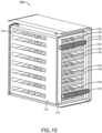
- FIGS. 7-10 exemplary embodiments of the oven 104 are shown.
- the oven 104 of FIGS. 7-10 may be implemented similarly and function similarly as the embodiments of the oven 104 depicted in and described with respect to FIGS. 2-6 , except that the oven 104 of FIGS. 7-10 may have at least two horizontal tangential fans 130 and separate heating elements 128.
- FIGS. 11-13 exemplary embodiments of the oven 104 are shown.
- the oven 104 of FIGS. 11-13 may be implemented similarly and function similarly as the embodiments of the oven 104 depicted in and described with respect to FIGS. 2-6 , except that the oven 104 of FIGS. 11-13 may have at least two vertical tangential fans 130 and separate heating elements 128.
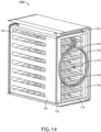
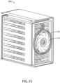
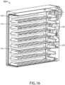
- FIGS. 14-16 exemplary embodiments of the oven 104 are shown.
- the oven 104 of FIGS. 14-16 may be implemented similarly and function similarly as the embodiments of the oven 104 depicted in and described with respect to FIGS. 2-6 , except that the oven 104 of FIGS. 14-16 may have a central radial fan and a central heating element 128 implemented around the radial fan 130.
- embodiments of invention disclosed herein are directed to a system including an oven.
- At least one means one or a plurality of; for example, “at least one” may comprise one, two, three, ..., one hundred, or more.
- one or more means one or a plurality of; for example, “one or more” may comprise one, two, three, ..., one hundred, or more.
- zero or more means zero, one, or a plurality of; for example, “zero or more” may comprise zero, one, two, three, ... , one hundred, or more.
Landscapes
- Engineering & Computer Science (AREA)
- Food Science & Technology (AREA)
- Life Sciences & Earth Sciences (AREA)
- Chemical & Material Sciences (AREA)
- Combustion & Propulsion (AREA)
- Mechanical Engineering (AREA)
- General Engineering & Computer Science (AREA)
- Aviation & Aerospace Engineering (AREA)
- Baking, Grill, Roasting (AREA)
- Electric Stoves And Ranges (AREA)
- Devices For Warming Or Keeping Food Or Tableware Hot (AREA)
- Cold Air Circulating Systems And Constructional Details In Refrigerators (AREA)
Claims (13)
- Système, comprenant :un four (104), comprenant :des parois de four internes (110) définissant une cavité à l'intérieur du four, dans lequel le four a un avant et un arrière (116) ;un porte-repas (120) positionné à l'intérieur de la cavité du four, le porte-repas ayant un avant et un arrière correspondant respectivement à l'avant et à l'arrière (116) du four, le porte-repas (120) comportant une paroi supérieure (124), deux parois latérales (134) et une paroi inférieure (126), l'avant et l'arrière du porte-repas (120) étant ouverts pour permettre un écoulement d'air à travers le porte-repas (120) depuis l'arrière du four à l'avant du four, le porte-repas (120) comportant une pluralité de plateaux-repas (122) positionnés généralement parallèlement à la paroi supérieure (124) et à la paroi inférieure (126) du porte-repas (120) ;au moins un élément chauffant (128) configuré pour chauffer l'air dans le four, l'au moins un élément chauffant (128) étant positionné entre le porte-repas (120) et l'arrière (116) du four ; etau moins un ventilateur (130), l'au moins un ventilateur (130) étant configuré pour :souffler l'air aspiré sur l'au moins un élément chauffant (128) pour produire de l'air chauffé ; etdistribuer l'air chauffé à travers le porte-repas (120) entre les plateaux-repas de la pluralité de plateaux-repas (122) ;caractérisé en ce que : l'au moins un ventilateur (130) est positionné entre l'arrière du four (116) et l'au moins un élément chauffant (128), et est configuré pour aspirer l'air de l'avant du four entre le porte-repas (6) et les parois de four internes à l'arrière du four (116) ; et en ce que le système comprend en outre au moins deux déflecteurs d'air (136) configurés pour diriger l'air de l'avant du four entre le porte-repas (120) et les parois de four internes (110) vers l'arrière (116) du four tout en empêchant l'air chauffé de l'au moins un ventilateur (130) de souffler entre le porte-repas (120) et les parois de four internes (110).
- Système selon la revendication 1, comprenant en outre au moins un déflecteur d'air (132) positionné entre la pluralité de plateaux-repas (122) et l'au moins un élément chauffant (128), chacun de l'au moins un déflecteur d'air (132) étant configuré pour diriger l'air chauffé entre deux plateaux-repas de la pluralité de plateaux-repas (122) ;
dans lequel chacun de l'au moins un déflecteur d'air (132) est positionné à une hauteur entre les hauteurs de deux plateaux-repas de la pluralité de plateaux-repas (122). - Système selon une quelconque revendication précédente, dans lequel les au moins deux déflecteurs d'air (136) sont quatre déflecteurs d'air (136), dans lequel l'un des quatre déflecteurs d'air (136) s'étend, au moins en partie, depuis la paroi supérieure (124) du porte-repas (120) vers l'arrière (116) du four, dans lequel un autre des quatre déflecteurs d'air (136) s'étend, au moins en partie, depuis la paroi inférieure (126) du porte-repas vers l'arrière (116) du four, dans lequel deux des quatre déflecteurs d'air (136) s'étendent, au moins en partie, depuis les deux parois latérales (134) du porte-repas (120) vers l'arrière (116) du four.
- Système selon la revendication 1, comprenant en outre au moins un déflecteur d'air (132), l'au moins un déflecteur d'air (132) étant positionné entre la pluralité de plateaux-repas (122) et l'au moins un élément chauffant (128), chacun de l'au moins un déflecteur d'air (132) étant configuré pour diriger l'air chauffé entre deux plateaux-repas de la pluralité de plateaux-repas (122), dans lequel chacun de l'au moins un déflecteur d'air (132) est positionné à une même hauteur qu'une hauteur de l'un de la pluralité de plateaux-repas (122).
- Système selon une quelconque revendication précédente, comprenant en outre une plaque de chicane (140) positionnée entre les plateaux-repas (122) et l'au moins un élément chauffant (128), la plaque de chicane (140) comportant une pluralité de chicanes (138) et une pluralité d'ouvertures (142), la plaque de chicane (140) étant configurée pour diriger l'air chauffé entre les plateaux-repas de la pluralité de plateaux-repas (122).
- Système selon une quelconque revendication précédente, dans lequel l'au moins un ventilateur (130) comprend au moins deux ventilateurs (130) agencés verticalement.
- Système selon une quelconque revendication précédente, dans lequel l'au moins un ventilateur (130) comprend au moins deux ventilateurs (130) agencés horizontalement.
- Système selon une quelconque revendication précédente, dans lequel au moins l'un de l'au moins un ventilateur (130) est un ventilateur radial.
- Système selon une quelconque revendication précédente, dans lequel au moins l'un de l'au moins un ventilateur (130) est un ventilateur axial ; ou dans lequel au moins l'un de l'au moins un ventilateur (130) est un ventilateur tangentiel.
- Système selon une quelconque revendication précédente, dans lequel chacun de l'au moins un élément chauffant (128) est positionné à une hauteur entre les hauteurs de deux plateaux-repas de la pluralité de plateaux-repas (122) ou à une même hauteur qu'une hauteur de l'un de la pluralité de plateaux-repas (122).
- Système selon une quelconque revendication précédente, dans lequel le four (104) est un insert de four d'une cuisine d'avion.
- Système selon la revendication 1, dans lequel le four (104) est mis en œuvre dans une cuisine d'aéronef ; et/ou dans lequel l'au moins un ventilateur (130) est au moins deux ventilateurs agencés verticalement.
- Cuisine d'aéronef, comprenant le système selon l'une quelconque des revendications 1 à 12, dans laquelle le four (104) est un insert de four dans la cuisine.
Applications Claiming Priority (1)
| Application Number | Priority Date | Filing Date | Title |
|---|---|---|---|
| US16/298,333 US11564396B2 (en) | 2019-03-11 | 2019-03-11 | Oven with improved airflow |
Publications (2)
| Publication Number | Publication Date |
|---|---|
| EP3708004A1 EP3708004A1 (fr) | 2020-09-16 |
| EP3708004B1 true EP3708004B1 (fr) | 2023-04-19 |
Family
ID=68916427
Family Applications (1)
| Application Number | Title | Priority Date | Filing Date |
|---|---|---|---|
| EP19216056.2A Active EP3708004B1 (fr) | 2019-03-11 | 2019-12-13 | Four à débit d'air amélioré |
Country Status (3)
| Country | Link |
|---|---|
| US (1) | US11564396B2 (fr) |
| EP (1) | EP3708004B1 (fr) |
| CN (1) | CN111671319B (fr) |
Families Citing this family (4)
| Publication number | Priority date | Publication date | Assignee | Title |
|---|---|---|---|---|
| AU2020314733B2 (en) | 2019-07-15 | 2022-07-14 | Sharkninja Operating Llc | Cooking device and components thereof |
| US12137838B2 (en) | 2020-12-30 | 2024-11-12 | Sharkninja Operating Llc | Cooking device and components thereof |
| US12117183B2 (en) * | 2021-01-29 | 2024-10-15 | B/E Aerospace, Inc. | Vehicle oven having an improved heating element |
| EP4372286A1 (fr) * | 2022-11-17 | 2024-05-22 | B/E Aerospace, Inc. | Insert de four |
Family Cites Families (24)
| Publication number | Priority date | Publication date | Assignee | Title |
|---|---|---|---|---|
| SE369828B (fr) * | 1973-01-26 | 1974-09-23 | Tipe Revent Ab | |
| JPS57155039A (en) | 1981-03-20 | 1982-09-25 | Matsushita Electric Ind Co Ltd | Cooking heater |
| GB2140914B (en) * | 1983-05-18 | 1987-05-20 | Link Food Systems Inc | Regeneration ovens |
| AT381620B (de) | 1984-03-13 | 1986-11-10 | Koenig Helmut | Backofen |
| AT383471B (de) | 1984-08-08 | 1987-07-10 | Koenig Helmut | Backofen |
| EP0401173A3 (fr) | 1989-05-31 | 1991-05-08 | Electrolux AG | Four pour cuire, rôtir et griller |
| US5228385A (en) * | 1992-03-03 | 1993-07-20 | Friedrich Metal Products Co., Inc. | Convection oven for bakery goods |
| US6252201B1 (en) * | 2000-01-06 | 2001-06-26 | Middleby Marshall Incorporated | Small fast acting conveyor toaster oven |
| US20070108179A1 (en) * | 2005-03-14 | 2007-05-17 | Hines Robert S Jr | Cooking oven |
| WO2008105581A1 (fr) * | 2007-01-17 | 2008-09-04 | Lg Electronics Inc. | Four |
| JP5437666B2 (ja) * | 2009-03-09 | 2014-03-12 | 株式会社ジャムコ | 旅客機搭載用スチームオーブンの加熱むら防止装置 |
| JP2010210118A (ja) | 2009-03-09 | 2010-09-24 | Jamco Corp | 漏水防止用安全弁を備えた旅客機搭載用スチームオーブン |
| EP2467646B1 (fr) * | 2009-08-19 | 2020-03-11 | Wolf Appliance, Inc. | Four |
| WO2012062875A1 (fr) | 2010-11-11 | 2012-05-18 | Arcelik Anonim Sirketi | Four à tubes échangeurs de chaleur |
| US20130156906A1 (en) * | 2011-12-14 | 2013-06-20 | J.K. Raghavan | Salamander Element for Closed System Oven |
| CN202723624U (zh) * | 2012-05-18 | 2013-02-13 | 九阳股份有限公司 | 热风循环装置及热风循环烧烤炉 |
| CN202665302U (zh) * | 2012-08-02 | 2013-01-16 | 黄振雄 | 一种热风电烤炉 |
| US11690478B2 (en) * | 2013-03-14 | 2023-07-04 | Timothy Kolb | Stackable cooking apparatus |
| US20150056355A1 (en) * | 2013-08-23 | 2015-02-26 | B/E Aerospace, Inc. | Toaster Broiler for Aircraft Galley |
| ITTO20131035A1 (it) * | 2013-12-17 | 2015-06-18 | Indesit Co Spa | Forno ventilato a riscaldamento diretto |
| CN106580118A (zh) * | 2016-12-09 | 2017-04-26 | 广东美的厨房电器制造有限公司 | 烤箱和烤箱的控制方法 |
| KR20190131043A (ko) | 2017-03-01 | 2019-11-25 | 벨쇼우브로스,인크 | 랙 오븐 및 이를 사용하는 시스템 |
| IT201700082197A1 (it) * | 2017-07-19 | 2019-01-19 | Tecnoeka S R L | Forno per la cottura degli alimenti |
| US11333364B2 (en) * | 2018-04-05 | 2022-05-17 | Rockwell Collins, Inc. | Adaptive cooking system |
-
2019
- 2019-03-11 US US16/298,333 patent/US11564396B2/en active Active
- 2019-12-13 EP EP19216056.2A patent/EP3708004B1/fr active Active
-
2020
- 2020-02-04 CN CN202010079863.8A patent/CN111671319B/zh active Active
Also Published As
| Publication number | Publication date |
|---|---|
| CN111671319B (zh) | 2024-12-06 |
| EP3708004A1 (fr) | 2020-09-16 |
| US20200288725A1 (en) | 2020-09-17 |
| US11564396B2 (en) | 2023-01-31 |
| CN111671319A (zh) | 2020-09-18 |
Similar Documents
| Publication | Publication Date | Title |
|---|---|---|
| EP3708004B1 (fr) | Four à débit d'air amélioré | |
| US8528537B2 (en) | Combustion and cooling airflow system for a cooking appliance | |
| US5025775A (en) | Air delivery system and oven control circuitry cooling system for a low profile impingement oven | |
| EP3302191B1 (fr) | Four à convection comportant des plénums d'air amovibles | |
| US5816234A (en) | Convection oven | |
| US10371391B2 (en) | Cooking oven provided for heat transfer by convection | |
| US20110083657A1 (en) | Oven air flow arrangement | |
| EP3084312B1 (fr) | Four à convection à chauffage direct | |
| JP5054992B2 (ja) | 空冷装置及び空冷方法 | |
| JP6148723B2 (ja) | 最適化された空気流を有する車両用オーブン | |
| US6054686A (en) | Uniform air flow oven | |
| US10842155B2 (en) | Baking drawer and method of circulating air within the baking drawer | |
| EP3671045B1 (fr) | Four d'avion avec porte-repas | |
| CN110199156A (zh) | 热干扰减少的用于净化循环烤箱空气的系统 | |
| EP2241820B1 (fr) | Four doté d'un refroidissement externe et methode d'operation | |
| AU2011227241A1 (en) | An oven for heating food | |
| US12590707B2 (en) | System and method for improved convection airflow in a cooking appliance | |
| JP6308662B2 (ja) | 2温度式のショーケース | |
| ES2866412T3 (es) | Encimera de cocción y sistema de enfriamiento de la encimera de cocción | |
| EP0593212A1 (fr) | Unités de présentation réfrigérées | |
| ITTO20131034A1 (it) | Forno ventilato a riscaldamento diretto | |
| CN213850230U (zh) | 一种食品保温柜 | |
| TR2022017306A1 (tr) | Aerodi̇nami̇k raf yani kanallarina sahi̇p bi̇r enerji̇ depolama si̇stemi̇ | |
| ITTO20131035A1 (it) | Forno ventilato a riscaldamento diretto | |
| JP2019076566A (ja) | 処理装置 |
Legal Events
| Date | Code | Title | Description |
|---|---|---|---|
| PUAI | Public reference made under article 153(3) epc to a published international application that has entered the european phase |
Free format text: ORIGINAL CODE: 0009012 |
|
| STAA | Information on the status of an ep patent application or granted ep patent |
Free format text: STATUS: THE APPLICATION HAS BEEN PUBLISHED |
|
| AK | Designated contracting states |
Kind code of ref document: A1 Designated state(s): AL AT BE BG CH CY CZ DE DK EE ES FI FR GB GR HR HU IE IS IT LI LT LU LV MC MK MT NL NO PL PT RO RS SE SI SK SM TR |
|
| AX | Request for extension of the european patent |
Extension state: BA ME |
|
| STAA | Information on the status of an ep patent application or granted ep patent |
Free format text: STATUS: REQUEST FOR EXAMINATION WAS MADE |
|
| 17P | Request for examination filed |
Effective date: 20210315 |
|
| RBV | Designated contracting states (corrected) |
Designated state(s): AL AT BE BG CH CY CZ DE DK EE ES FI FR GB GR HR HU IE IS IT LI LT LU LV MC MK MT NL NO PL PT RO RS SE SI SK SM TR |
|
| RAP3 | Party data changed (applicant data changed or rights of an application transferred) |
Owner name: B/E AEROSPACE, INC. |
|
| GRAP | Despatch of communication of intention to grant a patent |
Free format text: ORIGINAL CODE: EPIDOSNIGR1 |
|
| STAA | Information on the status of an ep patent application or granted ep patent |
Free format text: STATUS: GRANT OF PATENT IS INTENDED |
|
| INTG | Intention to grant announced |
Effective date: 20230110 |
|
| GRAS | Grant fee paid |
Free format text: ORIGINAL CODE: EPIDOSNIGR3 |
|
| GRAA | (expected) grant |
Free format text: ORIGINAL CODE: 0009210 |
|
| STAA | Information on the status of an ep patent application or granted ep patent |
Free format text: STATUS: THE PATENT HAS BEEN GRANTED |
|
| AK | Designated contracting states |
Kind code of ref document: B1 Designated state(s): AL AT BE BG CH CY CZ DE DK EE ES FI FR GB GR HR HU IE IS IT LI LT LU LV MC MK MT NL NO PL PT RO RS SE SI SK SM TR |
|
| REG | Reference to a national code |
Ref country code: GB Ref legal event code: FG4D |
|
| REG | Reference to a national code |
Ref country code: DE Ref legal event code: R096 Ref document number: 602019027698 Country of ref document: DE |
|
| REG | Reference to a national code |
Ref country code: CH Ref legal event code: EP |
|
| REG | Reference to a national code |
Ref country code: NL Ref legal event code: FP |
|
| REG | Reference to a national code |
Ref country code: IE Ref legal event code: FG4D |
|
| REG | Reference to a national code |
Ref country code: AT Ref legal event code: REF Ref document number: 1560539 Country of ref document: AT Kind code of ref document: T Effective date: 20230515 |
|
| REG | Reference to a national code |
Ref country code: LT Ref legal event code: MG9D |
|
| REG | Reference to a national code |
Ref country code: AT Ref legal event code: MK05 Ref document number: 1560539 Country of ref document: AT Kind code of ref document: T Effective date: 20230419 |
|
| PG25 | Lapsed in a contracting state [announced via postgrant information from national office to epo] |
Ref country code: SE Free format text: LAPSE BECAUSE OF FAILURE TO SUBMIT A TRANSLATION OF THE DESCRIPTION OR TO PAY THE FEE WITHIN THE PRESCRIBED TIME-LIMIT Effective date: 20230419 Ref country code: PT Free format text: LAPSE BECAUSE OF FAILURE TO SUBMIT A TRANSLATION OF THE DESCRIPTION OR TO PAY THE FEE WITHIN THE PRESCRIBED TIME-LIMIT Effective date: 20230821 Ref country code: NO Free format text: LAPSE BECAUSE OF FAILURE TO SUBMIT A TRANSLATION OF THE DESCRIPTION OR TO PAY THE FEE WITHIN THE PRESCRIBED TIME-LIMIT Effective date: 20230719 Ref country code: ES Free format text: LAPSE BECAUSE OF FAILURE TO SUBMIT A TRANSLATION OF THE DESCRIPTION OR TO PAY THE FEE WITHIN THE PRESCRIBED TIME-LIMIT Effective date: 20230419 Ref country code: AT Free format text: LAPSE BECAUSE OF FAILURE TO SUBMIT A TRANSLATION OF THE DESCRIPTION OR TO PAY THE FEE WITHIN THE PRESCRIBED TIME-LIMIT Effective date: 20230419 |
|
| PG25 | Lapsed in a contracting state [announced via postgrant information from national office to epo] |
Ref country code: RS Free format text: LAPSE BECAUSE OF FAILURE TO SUBMIT A TRANSLATION OF THE DESCRIPTION OR TO PAY THE FEE WITHIN THE PRESCRIBED TIME-LIMIT Effective date: 20230419 Ref country code: PL Free format text: LAPSE BECAUSE OF FAILURE TO SUBMIT A TRANSLATION OF THE DESCRIPTION OR TO PAY THE FEE WITHIN THE PRESCRIBED TIME-LIMIT Effective date: 20230419 Ref country code: LV Free format text: LAPSE BECAUSE OF FAILURE TO SUBMIT A TRANSLATION OF THE DESCRIPTION OR TO PAY THE FEE WITHIN THE PRESCRIBED TIME-LIMIT Effective date: 20230419 Ref country code: LT Free format text: LAPSE BECAUSE OF FAILURE TO SUBMIT A TRANSLATION OF THE DESCRIPTION OR TO PAY THE FEE WITHIN THE PRESCRIBED TIME-LIMIT Effective date: 20230419 Ref country code: IS Free format text: LAPSE BECAUSE OF FAILURE TO SUBMIT A TRANSLATION OF THE DESCRIPTION OR TO PAY THE FEE WITHIN THE PRESCRIBED TIME-LIMIT Effective date: 20230819 Ref country code: HR Free format text: LAPSE BECAUSE OF FAILURE TO SUBMIT A TRANSLATION OF THE DESCRIPTION OR TO PAY THE FEE WITHIN THE PRESCRIBED TIME-LIMIT Effective date: 20230419 Ref country code: GR Free format text: LAPSE BECAUSE OF FAILURE TO SUBMIT A TRANSLATION OF THE DESCRIPTION OR TO PAY THE FEE WITHIN THE PRESCRIBED TIME-LIMIT Effective date: 20230720 |
|
| PG25 | Lapsed in a contracting state [announced via postgrant information from national office to epo] |
Ref country code: FI Free format text: LAPSE BECAUSE OF FAILURE TO SUBMIT A TRANSLATION OF THE DESCRIPTION OR TO PAY THE FEE WITHIN THE PRESCRIBED TIME-LIMIT Effective date: 20230419 |
|
| PG25 | Lapsed in a contracting state [announced via postgrant information from national office to epo] |
Ref country code: SK Free format text: LAPSE BECAUSE OF FAILURE TO SUBMIT A TRANSLATION OF THE DESCRIPTION OR TO PAY THE FEE WITHIN THE PRESCRIBED TIME-LIMIT Effective date: 20230419 |
|
| REG | Reference to a national code |
Ref country code: DE Ref legal event code: R097 Ref document number: 602019027698 Country of ref document: DE |
|
| PG25 | Lapsed in a contracting state [announced via postgrant information from national office to epo] |
Ref country code: SM Free format text: LAPSE BECAUSE OF FAILURE TO SUBMIT A TRANSLATION OF THE DESCRIPTION OR TO PAY THE FEE WITHIN THE PRESCRIBED TIME-LIMIT Effective date: 20230419 Ref country code: SK Free format text: LAPSE BECAUSE OF FAILURE TO SUBMIT A TRANSLATION OF THE DESCRIPTION OR TO PAY THE FEE WITHIN THE PRESCRIBED TIME-LIMIT Effective date: 20230419 Ref country code: RO Free format text: LAPSE BECAUSE OF FAILURE TO SUBMIT A TRANSLATION OF THE DESCRIPTION OR TO PAY THE FEE WITHIN THE PRESCRIBED TIME-LIMIT Effective date: 20230419 Ref country code: EE Free format text: LAPSE BECAUSE OF FAILURE TO SUBMIT A TRANSLATION OF THE DESCRIPTION OR TO PAY THE FEE WITHIN THE PRESCRIBED TIME-LIMIT Effective date: 20230419 Ref country code: DK Free format text: LAPSE BECAUSE OF FAILURE TO SUBMIT A TRANSLATION OF THE DESCRIPTION OR TO PAY THE FEE WITHIN THE PRESCRIBED TIME-LIMIT Effective date: 20230419 Ref country code: CZ Free format text: LAPSE BECAUSE OF FAILURE TO SUBMIT A TRANSLATION OF THE DESCRIPTION OR TO PAY THE FEE WITHIN THE PRESCRIBED TIME-LIMIT Effective date: 20230419 |
|
| PLBE | No opposition filed within time limit |
Free format text: ORIGINAL CODE: 0009261 |
|
| STAA | Information on the status of an ep patent application or granted ep patent |
Free format text: STATUS: NO OPPOSITION FILED WITHIN TIME LIMIT |
|
| 26N | No opposition filed |
Effective date: 20240122 |
|
| PG25 | Lapsed in a contracting state [announced via postgrant information from national office to epo] |
Ref country code: SI Free format text: LAPSE BECAUSE OF FAILURE TO SUBMIT A TRANSLATION OF THE DESCRIPTION OR TO PAY THE FEE WITHIN THE PRESCRIBED TIME-LIMIT Effective date: 20230419 |
|
| PG25 | Lapsed in a contracting state [announced via postgrant information from national office to epo] |
Ref country code: SI Free format text: LAPSE BECAUSE OF FAILURE TO SUBMIT A TRANSLATION OF THE DESCRIPTION OR TO PAY THE FEE WITHIN THE PRESCRIBED TIME-LIMIT Effective date: 20230419 Ref country code: IT Free format text: LAPSE BECAUSE OF FAILURE TO SUBMIT A TRANSLATION OF THE DESCRIPTION OR TO PAY THE FEE WITHIN THE PRESCRIBED TIME-LIMIT Effective date: 20230419 |
|
| REG | Reference to a national code |
Ref country code: CH Ref legal event code: PL |
|
| PG25 | Lapsed in a contracting state [announced via postgrant information from national office to epo] |
Ref country code: LU Free format text: LAPSE BECAUSE OF NON-PAYMENT OF DUE FEES Effective date: 20231213 |
|
| PG25 | Lapsed in a contracting state [announced via postgrant information from national office to epo] |
Ref country code: MC Free format text: LAPSE BECAUSE OF FAILURE TO SUBMIT A TRANSLATION OF THE DESCRIPTION OR TO PAY THE FEE WITHIN THE PRESCRIBED TIME-LIMIT Effective date: 20230419 |
|
| REG | Reference to a national code |
Ref country code: BE Ref legal event code: MM Effective date: 20231231 |
|
| PG25 | Lapsed in a contracting state [announced via postgrant information from national office to epo] |
Ref country code: MC Free format text: LAPSE BECAUSE OF FAILURE TO SUBMIT A TRANSLATION OF THE DESCRIPTION OR TO PAY THE FEE WITHIN THE PRESCRIBED TIME-LIMIT Effective date: 20230419 Ref country code: LU Free format text: LAPSE BECAUSE OF NON-PAYMENT OF DUE FEES Effective date: 20231213 |
|
| REG | Reference to a national code |
Ref country code: IE Ref legal event code: MM4A |
|
| PG25 | Lapsed in a contracting state [announced via postgrant information from national office to epo] |
Ref country code: IE Free format text: LAPSE BECAUSE OF NON-PAYMENT OF DUE FEES Effective date: 20231213 |
|
| PG25 | Lapsed in a contracting state [announced via postgrant information from national office to epo] |
Ref country code: BE Free format text: LAPSE BECAUSE OF NON-PAYMENT OF DUE FEES Effective date: 20231231 |
|
| PG25 | Lapsed in a contracting state [announced via postgrant information from national office to epo] |
Ref country code: CH Free format text: LAPSE BECAUSE OF NON-PAYMENT OF DUE FEES Effective date: 20231231 |
|
| PG25 | Lapsed in a contracting state [announced via postgrant information from national office to epo] |
Ref country code: IE Free format text: LAPSE BECAUSE OF NON-PAYMENT OF DUE FEES Effective date: 20231213 Ref country code: CH Free format text: LAPSE BECAUSE OF NON-PAYMENT OF DUE FEES Effective date: 20231231 Ref country code: BE Free format text: LAPSE BECAUSE OF NON-PAYMENT OF DUE FEES Effective date: 20231231 |
|
| PG25 | Lapsed in a contracting state [announced via postgrant information from national office to epo] |
Ref country code: BG Free format text: LAPSE BECAUSE OF FAILURE TO SUBMIT A TRANSLATION OF THE DESCRIPTION OR TO PAY THE FEE WITHIN THE PRESCRIBED TIME-LIMIT Effective date: 20230419 |
|
| PG25 | Lapsed in a contracting state [announced via postgrant information from national office to epo] |
Ref country code: BG Free format text: LAPSE BECAUSE OF FAILURE TO SUBMIT A TRANSLATION OF THE DESCRIPTION OR TO PAY THE FEE WITHIN THE PRESCRIBED TIME-LIMIT Effective date: 20230419 |
|
| PG25 | Lapsed in a contracting state [announced via postgrant information from national office to epo] |
Ref country code: CY Free format text: LAPSE BECAUSE OF FAILURE TO SUBMIT A TRANSLATION OF THE DESCRIPTION OR TO PAY THE FEE WITHIN THE PRESCRIBED TIME-LIMIT; INVALID AB INITIO Effective date: 20191213 |
|
| PG25 | Lapsed in a contracting state [announced via postgrant information from national office to epo] |
Ref country code: HU Free format text: LAPSE BECAUSE OF FAILURE TO SUBMIT A TRANSLATION OF THE DESCRIPTION OR TO PAY THE FEE WITHIN THE PRESCRIBED TIME-LIMIT; INVALID AB INITIO Effective date: 20191213 |
|
| PG25 | Lapsed in a contracting state [announced via postgrant information from national office to epo] |
Ref country code: TR Free format text: LAPSE BECAUSE OF FAILURE TO SUBMIT A TRANSLATION OF THE DESCRIPTION OR TO PAY THE FEE WITHIN THE PRESCRIBED TIME-LIMIT Effective date: 20230419 |
|
| PGFP | Annual fee paid to national office [announced via postgrant information from national office to epo] |
Ref country code: NL Payment date: 20251119 Year of fee payment: 7 |
|
| PGFP | Annual fee paid to national office [announced via postgrant information from national office to epo] |
Ref country code: DE Payment date: 20251126 Year of fee payment: 7 |
|
| PGFP | Annual fee paid to national office [announced via postgrant information from national office to epo] |
Ref country code: GB Payment date: 20251119 Year of fee payment: 7 |
|
| PGFP | Annual fee paid to national office [announced via postgrant information from national office to epo] |
Ref country code: FR Payment date: 20251120 Year of fee payment: 7 |
|
| P01 | Opt-out of the competence of the unified patent court (upc) registered |
Free format text: CASE NUMBER: UPC_APP_0019054_3708004/2025 Effective date: 20251222 |