EP3708385A1 - Systèmes et de dispositifs de freinage réagissant à une charge - Google Patents
Systèmes et de dispositifs de freinage réagissant à une charge Download PDFInfo
- Publication number
- EP3708385A1 EP3708385A1 EP20166461.2A EP20166461A EP3708385A1 EP 3708385 A1 EP3708385 A1 EP 3708385A1 EP 20166461 A EP20166461 A EP 20166461A EP 3708385 A1 EP3708385 A1 EP 3708385A1
- Authority
- EP
- European Patent Office
- Prior art keywords
- axle
- roller
- load
- plunger
- braking
- Prior art date
- Legal status (The legal status is an assumption and is not a legal conclusion. Google has not performed a legal analysis and makes no representation as to the accuracy of the status listed.)
- Granted
Links
Images
Classifications
-
- B—PERFORMING OPERATIONS; TRANSPORTING
- B65—CONVEYING; PACKING; STORING; HANDLING THIN OR FILAMENTARY MATERIAL
- B65G—TRANSPORT OR STORAGE DEVICES, e.g. CONVEYORS FOR LOADING OR TIPPING, SHOP CONVEYOR SYSTEMS OR PNEUMATIC TUBE CONVEYORS
- B65G13/00—Roller-ways
- B65G13/075—Braking means
-
- B—PERFORMING OPERATIONS; TRANSPORTING
- B60—VEHICLES IN GENERAL
- B60B—VEHICLE WHEELS; CASTORS; AXLES FOR WHEELS OR CASTORS; INCREASING WHEEL ADHESION
- B60B33/00—Castors in general ; Anti-clogging castors
- B60B33/0036—Castors in general ; Anti-clogging castors characterised by type of wheels
- B60B33/0044—Roller type wheels, i.e. extra wide wheels
-
- B—PERFORMING OPERATIONS; TRANSPORTING
- B60—VEHICLES IN GENERAL
- B60B—VEHICLE WHEELS; CASTORS; AXLES FOR WHEELS OR CASTORS; INCREASING WHEEL ADHESION
- B60B33/00—Castors in general ; Anti-clogging castors
- B60B33/0047—Castors in general ; Anti-clogging castors characterised by details of the rolling axle
- B60B33/0049—Castors in general ; Anti-clogging castors characterised by details of the rolling axle the rolling axle being horizontal
-
- B—PERFORMING OPERATIONS; TRANSPORTING
- B60—VEHICLES IN GENERAL
- B60B—VEHICLE WHEELS; CASTORS; AXLES FOR WHEELS OR CASTORS; INCREASING WHEEL ADHESION
- B60B33/00—Castors in general ; Anti-clogging castors
- B60B33/006—Castors in general ; Anti-clogging castors characterised by details of the swivel mechanism
- B60B33/0063—Castors in general ; Anti-clogging castors characterised by details of the swivel mechanism no swivelling action, i.e. no real caster
-
- B—PERFORMING OPERATIONS; TRANSPORTING
- B60—VEHICLES IN GENERAL
- B60B—VEHICLE WHEELS; CASTORS; AXLES FOR WHEELS OR CASTORS; INCREASING WHEEL ADHESION
- B60B33/00—Castors in general ; Anti-clogging castors
- B60B33/0078—Castors in general ; Anti-clogging castors characterised by details of the wheel braking mechanism
- B60B33/0086—Castors in general ; Anti-clogging castors characterised by details of the wheel braking mechanism acting on rim or side portion of tyre
-
- B—PERFORMING OPERATIONS; TRANSPORTING
- B60—VEHICLES IN GENERAL
- B60B—VEHICLE WHEELS; CASTORS; AXLES FOR WHEELS OR CASTORS; INCREASING WHEEL ADHESION
- B60B33/00—Castors in general ; Anti-clogging castors
- B60B33/0078—Castors in general ; Anti-clogging castors characterised by details of the wheel braking mechanism
- B60B33/0094—Castors in general ; Anti-clogging castors characterised by details of the wheel braking mechanism actuated automatically
-
- B—PERFORMING OPERATIONS; TRANSPORTING
- B64—AIRCRAFT; AVIATION; COSMONAUTICS
- B64D—EQUIPMENT FOR FITTING IN OR TO AIRCRAFT; FLIGHT SUITS; PARACHUTES; ARRANGEMENT OR MOUNTING OF POWER PLANTS OR PROPULSION TRANSMISSIONS IN AIRCRAFT
- B64D9/00—Equipment for handling freight; Equipment for facilitating passenger embarkation or the like
- B64D2009/006—Rollers or drives for pallets of freight containers, e.g. PDU
-
- B—PERFORMING OPERATIONS; TRANSPORTING
- B65—CONVEYING; PACKING; STORING; HANDLING THIN OR FILAMENTARY MATERIAL
- B65G—TRANSPORT OR STORAGE DEVICES, e.g. CONVEYORS FOR LOADING OR TIPPING, SHOP CONVEYOR SYSTEMS OR PNEUMATIC TUBE CONVEYORS
- B65G2205/00—Stopping elements used in conveyors to stop articles or arrays of articles
- B65G2205/02—Stopping elements used in conveyors to stop articles or arrays of articles where the stop device is adaptable to the size of the article or array
-
- F—MECHANICAL ENGINEERING; LIGHTING; HEATING; WEAPONS; BLASTING
- F16—ENGINEERING ELEMENTS AND UNITS; GENERAL MEASURES FOR PRODUCING AND MAINTAINING EFFECTIVE FUNCTIONING OF MACHINES OR INSTALLATIONS; THERMAL INSULATION IN GENERAL
- F16D—COUPLINGS FOR TRANSMITTING ROTATION; CLUTCHES; BRAKES
- F16D51/00—Brakes with outwardly-movable braking members co-operating with the inner surface of a drum or the like
Definitions
- the disclosure relates generally to reactive load braking, and more particularly, to systems and devices for load reactive braking in cargo movement.
- Rollers, coasters, and other wheeled mechanisms are often used to move loads.
- the rollers may have an associated braking mechanism to prevent loss of control.
- braking rollers may have the braking arrangement preset at or near the maximum braking load that is selected for a maximum weight cargo container at the maximum angle of the cargo floor.
- the strong brakes on the rollers are too powerful to allow the roller to roll under light loads.
- Braking rollers often have a friction material around the outer surface. In instances where the load applied to the roller is not enough to overcome the braking mechanism, the container skids over the roller and creates flat spots on the roller.
- a roller assembly comprising a housing having an outer surface attached thereto, and a braking arrangement positioned at least partially within the housing.
- the braking arrangement is configured to increase resistance to rotation of the housing proportionally to a load applied against the outer surface.
- the roller assembly may include a linkage coupled to the axle and a roller support structure pivotally coupled to the linkage.
- the linkage may be configured to pivot relative to the axle and the roller support structure in response to the load on the outer surface.
- the roller assembly may also include an axle interface disposed at a distal end of axle and a roller support structure having an angled surface.
- the axle interface may be configured to engage the angled surface.
- the axle may also include a first plunger and a second plunger configured to apply the compressive force to the braking arrangement. A preload adjustment may urge the first plunger toward the second plunger.
- the axle may also comprise a pilot configured to maintain alignment of the axle.
- a bearing may be disposed radially inward from the housing, and the axle may slideably engage an inner diameter of the bearing.
- a roller assembly for a cargo loading system may include an outer surface, a housing radially inward from the outer surface, a bearing retained within the housing, a braking arrangement retained within the housing, and an axle disposed at least partially within the housing.
- the axle may be configured to engage the bearing and apply a compressive force to the braking arrangement.
- the axle may be configured to apply the compressive force to the braking arrangement in response to a load on the outer surface.
- the compressive force may be applied to the braking arrangement proportionally to the load on the outer surface. Proportionally may be used to describe a linear relationship between the compressive force applied to the braking arrangement and the load on the outer surface.
- the braking arrangement may be configured to produce a braking force proportional to the load on the outer surface.
- the axle may include a first plunger and a second plunger configured to apply the compressive force to the braking arrangement.
- the first plunger and second plunger may also be configured to translate towards the braking arrangement in response a load on the outer surface.
- a preload adjustment may be configured to urge the first plunger toward the second plunger.
- a pilot may maintain alignment of the axle.
- a linkage may be coupled to the axle with a roller support structure pivotally coupled to the linkage. The linkage may pivot relative to the axle and the roller support structure in response to the load on the outer surface.
- the roller assembly may also include an axle interface disposed at a distal end of axle and a roller support structure having an angled surface. The axle interface may engage the angled surface. The axle may also slideably engage an inner diameter of the bearing.
- a method of applying reactive braking includes the steps of applying a load to an outer surface of a roller assembly, axially compressing a braking arrangement disposed at the roller assembly, and increasing resistance to rotation of the outer surface proportional to the load on the outer surface.
- Rollers of the present disclosure may apply a braking load that is a direct function of the weight applied to the roller (i.e., unit area load applied over the braking roller). This applied load on the braking rollers' outer surface results in the optimum braking load for a given container weight.
- a variable brake load may be adjusted.
- the variable brake load may be directly proportional to the containers' applied unit area load on the roller. Controlling the brake load below the load required to maintain traction on the braking roller tends to eliminate the slippage and wear and still provide suitable braking force for heavy loads.
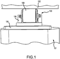
- roller assembly 100 may support cargo 102 on platform 104.
- Roller assembly 100 may be a cylindrical structure and coupled to a roller support structure 106 that is configured to retain roller 108 relative to platform 104.
- Roller 108 may include an internal braking mechanism configured to increase braking force in response to the mass of cargo 102.
- the braking force applied by roller assembly 100 may have a linear relationship with the mass of the load supported by roller assembly 100.
- roller assembly 100 may also be mounted to a floor to provide a rolling surface for cargo to move across.
- roller assembly 100 may be mounted to fixed locations in an aircraft cargo bay to enable loading and unloading of cargo with cargo 102 in direct contact with roller 108.
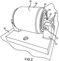
- roller 108 is shown mounted to roller support structure 106, in accordance with various embodiments.
- Roller 108 includes an outer surface 200 having friction characteristics suitable for providing traction on cargo containers.
- Outer surface 200 may thus be made of suitable rubbers (both natural and synthetic) and plastics having the desired friction characteristics.
- Housing 202 is disposed radially inward to and concentric with outer surface 200 and may be recessed relative to outer surface 200. In that regard, outer surface may protrude from housing 202 to make contact with a cargo container, the ground, or another surface.
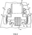
- FIG. 3 illustrates roller 108 in a disassembled state, in accordance with various embodiments.
- housing 202 may contain bearings 204.
- Bearing 204 may provide support for housing 202 as housing 202 rotates about an axle 205.
- Axle 205 and axle 305 may be halves of a split axle, as described in greater detail below, with the two halves of the split axle configured to translate relative to one another.
- Linkage 206 may be coupled to axle 205 and roller support structure 106 by fastener 210 extending through flanges 208 and linkage 206. Linkage 206 is thus pivotally coupled to roller support structure 106.
- Roller 108 may apply a braking force to cargo container 102 in response to a compressive force transmitted through axle 205 and/or axle 305 into brake arrangement 300.
- the braking force provided by brake arrangement 300 may be related to the angle of linkage 206 relative to roller support structure 106.
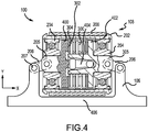
- Roller 108 is configured to rotate about axle 205, which extends in the x direction and may serve as both an axis of symmetry and an axis of rotation for roller assembly 100.
- Linkages 206 mechanically couple axle 205 to roller support structure 106 at an angle with the mounting point of linkage 206 to axle 205 offset in the y direction from the mounting point of linkage 206 to roller support structure 106.
- the angle of linkage 206 may be oriented so that an increased load on outer surface 200 of roller in the y direction urges roller 108 towards base 406 of roller support structure 106.
- increased load on outer surface 200 of roller 108 in the y direction may decrease the offset in the y direction of mounting point of linkage 206 to axle 205 from the mounting point of linkage 206 to roller support structure 106, thereby generating a compressive force on axle 205 in the x direction.
- Axle 205 may act as a spring in the x direction and compress in the x direction in in response to a load applied to outer surface 200 in the y direction.
- a separate biasing member such as a torsion spring can be positioned and configured to urge the axles 205, 305 in the Y direction opposite to that of the load applied to the outer surface 200.
- Axle 205 may decompress or expand in the x direction back to its original state in response to the load being removed from outer surface 200.
- Axle 205 may slideably engage an inner diameter of bearing 204 as the axle compresses and decompresses.
- axle 205 may comprise plunger 400 and axle 305 may comprise plunger 402 with the plungers disposed radially inward from outer surface 200.
- Plunger 400 (and axle 205) may be configured to translate in the x direction relative to plunger 402 (and axle 305).
- Axle 205 and axle 305 may each be a portion of the complete axle extending through housing 202 and supports bearings 204.
- Plunger 400 of axle 205 and a plunger 402 of axle 305 may thus be configured to apply compressive force to brake arrangement 300 in response to the compression of axle 305 and axle 205 in the x direction.
- brake arrangement 300 may comprise drive disks 304 and brake disks 302.
- Drive disks 304 may be coupled to housing 202 and configured to rotate with housing 202.
- Brake disks 302 may be coupled to axle 305, and thus may be rotationally fixed.
- Brake disks 302 may include friction media such as, for example, a skewed roller or friction pad configured to create friction with drive disks 304 in response to the compression of axle 305 and 205 in the x direction.
- a load applied at outer surface 200 in the y direction may cause linkage 206 to rotate about pivot 207, thereby urging axle 305 and axle 205 toward one another and thereby compressing drive disks 304 between brake disks 302.
- An increased axial (i.e., in the x direction) compressive load between brake disks 302 and drive disks 304 may increase braking force, which is proportional to the load on outer surface 200.
- brake arrangement 300 may be disposed between plunger 400 and plunger 402 and radially inward from outer surface 200. Brake arrangement 300 may resist rotation in response to the compressive force between plunger 400 towards plunger 402 generated in response to a load applied at outer surface 200. In response to a load being removed from outer surface 200, brake arrangement 300 may urge plunger 400 away from plunger 402. Brake arrangement 300 may thus provide the expanding force for the spring-like behavior of axle 305 and 205 by pushing outward in the x direction against plunger 400 and plunger 402 of axle 305 and 205.
- a pilot 404 extending in the x direction on axle 205 may maintain alignment with axle 305 and react any moment that might be generated by forces applied to outer surface 200 in the y direction. In that regard, pilot 404 may allow for plunger 400 and plunger 402 to move relative to one another axially (i.e., in the x direction) while maintaining alignment radially (i.e., in the y direction).
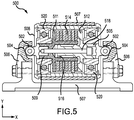
- roller 508 is configured to rotate about axle 505 and axle 509, which extends in the x direction.
- Roller 502 may be disposed at the distal ends of axle 505 and 509.
- Roller 502 may also be configured to engage angled surface 504 of support structure 506.
- Roller 502 may thus be a sliding interface or a rolling interface to engage angled surface 504 of support structure 506.
- Angled surface 504 of support structure 506 and 509 may be disposed at an angle relative to the y axis such that a compressive force is exerted on axle 505 and 509 in response to a load applied at outer surface 501 of roller 508.
- the angle of angled surface 504 relative to the y axis may be selected at least partially based on the desired level of braking in response to the magnitude of the load applied on outer surface 501.
- a load on outer surface 501 of roller 508 in the y direction may thus urge roller 508 towards base 507 of roller support structure 506.
- the distance spanned by axle 505 and 509 may be reduced based on the position of roller 502 on axle 505 and 509 on angled surface 504.
- increased load on outer surface 501 of roller 508 in the y direction may generate a compressive force on axle 505 and axle 509 in the x direction in response to the distance spanned by axle 505 and axle 509 decreasing.
- Axle 505 and axle 509 may act as a spring in the x direction and compress in the x direction in in response to a load applied to outer surface 501 in the y direction. Axle 505 and 509 may decompress or expand in the x direction back to its original state in response to the load being removed from outer surface 501. Axle 505 and axle 509 may slideably engage an inner diameter of bearing 520 as the axle compresses and decompresses.
- Axle 505 may comprise plunger 512 and axle 509 may comprise plunger 511 that translate in the x direction relative to one another.
- Plunger 511 of axle 509 and a plunger 512 of axle 505 may thus be configured to apply compressive force to brake arrangement 514 in response to the compression of axle 505 and 509.
- Brake arrangement 514 (similar to brake arrangement 300 in FIG. 4 ) may resist rotation in response to the compressive force between plunger 511 towards plunger 512 generated in response to a load applied at outer surface 501.
- brake arrangement 514 may urge plunger 511 away from plunger 512.
- Brake arrangement 514 may thus provide the expanding force for the spring-like behavior of axle 505 and axle 509 by pushing outward in the x direction against plunger 511 of axle 509 and plunger 512 of axle 505.
- a pilot 516 may maintain alignment of axle 505 and react any moment that might be generated by forces applied to outer surface 501 in the y direction.
- pilot 516 may allow for plunger 511 and plunger 512 to move relative to one another axially (i.e., in the x direction) while maintaining alignment radially (i.e., in the y direction).
- Axle 505 and axle 509 may also include a preloading adjustment 518.
- the preloading adjustment 518 may include, for example, a screw or other adjustable length rod that preloads roller assembly 500 by urging plunger 511 towards plunger 512 and applying a compressive force to brake arrangement 514.
- Shortening preloading adjustment 518 may increase the braking force applied to roller 508 absent a load on outer surface 501.
- the preload adjustment may apply a predetermined braking force from brake arrangement 514 until a load sufficient to press axle 505 further along angled surface 504 and overcome the expansive force of brake arrangement 514 at the preloaded level of compression.
- references to "one embodiment”, “an embodiment”, “an example embodiment”, etc. indicate that the embodiment described may include a particular feature, structure, or characteristic, but every embodiment may not necessarily include the particular feature, structure, or characteristic. Moreover, such phrases are not necessarily referring to the same embodiment. Further, when a particular feature, structure, or characteristic is described in connection with an embodiment, it is submitted that it is within the knowledge of one skilled in the art to affect such feature, structure, or characteristic in connection with other embodiments whether or not explicitly described. After reading the description, it will be apparent to one skilled in the relevant art(s) how to implement the disclosure in alternative embodiments. The scope of the invention is defined by the claims.
Landscapes
- Engineering & Computer Science (AREA)
- Mechanical Engineering (AREA)
- Braking Arrangements (AREA)
- Rolling Contact Bearings (AREA)
Applications Claiming Priority (2)
| Application Number | Priority Date | Filing Date | Title |
|---|---|---|---|
| US15/154,556 US9845196B2 (en) | 2016-05-13 | 2016-05-13 | Load reactive braking systems and devices |
| EP17170994.2A EP3246176B1 (fr) | 2016-05-13 | 2017-05-15 | Systèmes et de dispositifs de freinage réagissant à une charge |
Related Parent Applications (2)
| Application Number | Title | Priority Date | Filing Date |
|---|---|---|---|
| EP17170994.2A Division-Into EP3246176B1 (fr) | 2016-05-13 | 2017-05-15 | Systèmes et de dispositifs de freinage réagissant à une charge |
| EP17170994.2A Division EP3246176B1 (fr) | 2016-05-13 | 2017-05-15 | Systèmes et de dispositifs de freinage réagissant à une charge |
Publications (2)
| Publication Number | Publication Date |
|---|---|
| EP3708385A1 true EP3708385A1 (fr) | 2020-09-16 |
| EP3708385B1 EP3708385B1 (fr) | 2025-04-30 |
Family
ID=58745029
Family Applications (2)
| Application Number | Title | Priority Date | Filing Date |
|---|---|---|---|
| EP20166461.2A Active EP3708385B1 (fr) | 2016-05-13 | 2017-05-15 | Agencement de roulage pour systeme de chargement |
| EP17170994.2A Active EP3246176B1 (fr) | 2016-05-13 | 2017-05-15 | Systèmes et de dispositifs de freinage réagissant à une charge |
Family Applications After (1)
| Application Number | Title | Priority Date | Filing Date |
|---|---|---|---|
| EP17170994.2A Active EP3246176B1 (fr) | 2016-05-13 | 2017-05-15 | Systèmes et de dispositifs de freinage réagissant à une charge |
Country Status (3)
| Country | Link |
|---|---|
| US (1) | US9845196B2 (fr) |
| EP (2) | EP3708385B1 (fr) |
| CN (1) | CN107444833B (fr) |
Families Citing this family (4)
| Publication number | Priority date | Publication date | Assignee | Title |
|---|---|---|---|---|
| US11053078B1 (en) | 2020-03-03 | 2021-07-06 | Goodrich Corporation | Load reactive braking systems and devices |
| EP4140923B1 (fr) * | 2021-08-27 | 2025-08-20 | Airbus Operations GmbH | Système de chargement de fret à commande dynamique pour un aéronef |
| US11772899B2 (en) | 2021-10-05 | 2023-10-03 | Goodrich Corporation | Cargo velocity control for cargo handling systems |
| US12415602B2 (en) * | 2022-08-12 | 2025-09-16 | Goodrich Corporation | Solenoid/magnetic hold brake with power off magnet hold function |
Citations (4)
| Publication number | Priority date | Publication date | Assignee | Title |
|---|---|---|---|---|
| US6131717A (en) * | 1998-06-05 | 2000-10-17 | Pemco Engineers | Braking roller |
| US6256835B1 (en) * | 1999-12-02 | 2001-07-10 | Taiwan Golden Ball Industrial Co., Ltd. | Caster with a locking mechanism |
| WO2006066417A1 (fr) * | 2004-12-24 | 2006-06-29 | Pare-Chute Inc. | Dispositif de descente de charge en rappel |
| US8109702B2 (en) * | 2008-08-28 | 2012-02-07 | Goodrich Corporation | Attenuated cargo caster |
Family Cites Families (6)
| Publication number | Priority date | Publication date | Assignee | Title |
|---|---|---|---|---|
| US3285377A (en) * | 1964-02-20 | 1966-11-15 | Formsprag Co | Torque released one way brake |
| US3713521A (en) * | 1970-10-12 | 1973-01-30 | Takenishi Seisakusho K K | Roller provided with speed controlling mechanism for articles being conveyed on a roller conveyor |
| JPS5982207A (ja) * | 1982-11-02 | 1984-05-12 | Toyota Motor Corp | ロ−ラ式搬送装置用制動機構付きロ−ラ |
| DE502006002577D1 (de) * | 2006-04-21 | 2009-02-26 | Interroll Holding Ag | Rolle mit Freilauf und Bremse |
| DE102010011725A1 (de) * | 2010-03-17 | 2011-09-22 | Haldex Brake Products Ab | Scheibenbremse und Herstellungsverfahren für eine Scheibenbremse |
| US11053078B1 (en) * | 2020-03-03 | 2021-07-06 | Goodrich Corporation | Load reactive braking systems and devices |
-
2016
- 2016-05-13 US US15/154,556 patent/US9845196B2/en active Active
-
2017
- 2017-05-12 CN CN201710334782.6A patent/CN107444833B/zh active Active
- 2017-05-15 EP EP20166461.2A patent/EP3708385B1/fr active Active
- 2017-05-15 EP EP17170994.2A patent/EP3246176B1/fr active Active
Patent Citations (4)
| Publication number | Priority date | Publication date | Assignee | Title |
|---|---|---|---|---|
| US6131717A (en) * | 1998-06-05 | 2000-10-17 | Pemco Engineers | Braking roller |
| US6256835B1 (en) * | 1999-12-02 | 2001-07-10 | Taiwan Golden Ball Industrial Co., Ltd. | Caster with a locking mechanism |
| WO2006066417A1 (fr) * | 2004-12-24 | 2006-06-29 | Pare-Chute Inc. | Dispositif de descente de charge en rappel |
| US8109702B2 (en) * | 2008-08-28 | 2012-02-07 | Goodrich Corporation | Attenuated cargo caster |
Also Published As
| Publication number | Publication date |
|---|---|
| US20170327315A1 (en) | 2017-11-16 |
| EP3246176A1 (fr) | 2017-11-22 |
| US9845196B2 (en) | 2017-12-19 |
| CN107444833A (zh) | 2017-12-08 |
| EP3246176B1 (fr) | 2020-05-06 |
| CN107444833B (zh) | 2020-08-11 |
| EP3708385B1 (fr) | 2025-04-30 |
Similar Documents
| Publication | Publication Date | Title |
|---|---|---|
| EP3246176B1 (fr) | Systèmes et de dispositifs de freinage réagissant à une charge | |
| US5402560A (en) | Bearing setting apparatus | |
| EP0960811B1 (fr) | Vis à billes bidirectionelle et autoblocante | |
| CN105270605B (zh) | 混合转矩限制旋转止回装置 | |
| US6487775B2 (en) | Bearing assembly adjustable spacer and system for adjusting the same | |
| CN1818409B (zh) | 无反力及转矩限制器的联合装置 | |
| CA2734341C (fr) | Frein a cone sans flasque | |
| US20100187367A1 (en) | Spring track roller assembly | |
| KR102733866B1 (ko) | 주차 브레이크 장치 | |
| US9989114B2 (en) | Power transfer mechanism for a parking brake assembly | |
| JP5576368B2 (ja) | ディスクブレーキ用の調整装置 | |
| US6974015B2 (en) | One-way bidirectional clutch | |
| EP4269287B1 (fr) | Systèmes et dispositifs de freinage à réaction de charge | |
| WO2015193207A1 (fr) | Actionneur electromecanique a limiteur de couple magnetique | |
| WO2011067864A1 (fr) | Dispositif manipulateur du type à bras pivotant | |
| US9889833B2 (en) | Integrated parking brake for disk brake | |
| US11691848B2 (en) | Safely brake for an elevator | |
| US20070137970A1 (en) | Conical clutch pack actuator especially for a transfer case | |
| US20070119664A1 (en) | Electromechanical aircraft brake with tiltable actuators | |
| US20130122790A1 (en) | Contrast device for the grinding of products held between centres | |
| WO2016143908A1 (fr) | Dispositif de frein à disque | |
| FR3105170A1 (fr) | Manche de pilotage d’un aéronef comprenant un rapport de réduction global amélioré et procédé d’utilisation d’un tel manche | |
| US20060054429A1 (en) | Ball ramp caliper brake | |
| CN210830253U (zh) | 盘式制动器中间隙自调机构的主调总成 | |
| US5988890A (en) | Rotor shaft |
Legal Events
| Date | Code | Title | Description |
|---|---|---|---|
| PUAI | Public reference made under article 153(3) epc to a published international application that has entered the european phase |
Free format text: ORIGINAL CODE: 0009012 |
|
| STAA | Information on the status of an ep patent application or granted ep patent |
Free format text: STATUS: THE APPLICATION HAS BEEN PUBLISHED |
|
| AC | Divisional application: reference to earlier application |
Ref document number: 3246176 Country of ref document: EP Kind code of ref document: P |
|
| AK | Designated contracting states |
Kind code of ref document: A1 Designated state(s): AL AT BE BG CH CY CZ DE DK EE ES FI FR GB GR HR HU IE IS IT LI LT LU LV MC MK MT NL NO PL PT RO RS SE SI SK SM TR |
|
| STAA | Information on the status of an ep patent application or granted ep patent |
Free format text: STATUS: REQUEST FOR EXAMINATION WAS MADE |
|
| 17P | Request for examination filed |
Effective date: 20210315 |
|
| RBV | Designated contracting states (corrected) |
Designated state(s): AL AT BE BG CH CY CZ DE DK EE ES FI FR GB GR HR HU IE IS IT LI LT LU LV MC MK MT NL NO PL PT RO RS SE SI SK SM TR |
|
| STAA | Information on the status of an ep patent application or granted ep patent |
Free format text: STATUS: EXAMINATION IS IN PROGRESS |
|
| 17Q | First examination report despatched |
Effective date: 20221121 |
|
| P01 | Opt-out of the competence of the unified patent court (upc) registered |
Effective date: 20230922 |
|
| GRAP | Despatch of communication of intention to grant a patent |
Free format text: ORIGINAL CODE: EPIDOSNIGR1 |
|
| STAA | Information on the status of an ep patent application or granted ep patent |
Free format text: STATUS: GRANT OF PATENT IS INTENDED |
|
| RIC1 | Information provided on ipc code assigned before grant |
Ipc: B64D 9/00 20060101ALN20241119BHEP Ipc: B60P 1/52 20060101ALI20241119BHEP Ipc: B60B 33/00 20060101AFI20241119BHEP |
|
| INTG | Intention to grant announced |
Effective date: 20241129 |
|
| GRAS | Grant fee paid |
Free format text: ORIGINAL CODE: EPIDOSNIGR3 |
|
| GRAA | (expected) grant |
Free format text: ORIGINAL CODE: 0009210 |
|
| STAA | Information on the status of an ep patent application or granted ep patent |
Free format text: STATUS: THE PATENT HAS BEEN GRANTED |
|
| RIN1 | Information on inventor provided before grant (corrected) |
Inventor name: LARSON, WALLACE HAROLD |
|
| AC | Divisional application: reference to earlier application |
Ref document number: 3246176 Country of ref document: EP Kind code of ref document: P |
|
| AK | Designated contracting states |
Kind code of ref document: B1 Designated state(s): AL AT BE BG CH CY CZ DE DK EE ES FI FR GB GR HR HU IE IS IT LI LT LU LV MC MK MT NL NO PL PT RO RS SE SI SK SM TR |
|
| REG | Reference to a national code |
Ref country code: CH Ref legal event code: EP Ref country code: GB Ref legal event code: FG4D |
|
| REG | Reference to a national code |
Ref country code: IE Ref legal event code: FG4D |
|
| REG | Reference to a national code |
Ref country code: DE Ref legal event code: R096 Ref document number: 602017089266 Country of ref document: DE |
|
| REG | Reference to a national code |
Ref country code: NL Ref legal event code: MP Effective date: 20250430 |
|
| REG | Reference to a national code |
Ref country code: AT Ref legal event code: MK05 Ref document number: 1789710 Country of ref document: AT Kind code of ref document: T Effective date: 20250430 |
|
| PG25 | Lapsed in a contracting state [announced via postgrant information from national office to epo] |
Ref country code: FI Free format text: LAPSE BECAUSE OF FAILURE TO SUBMIT A TRANSLATION OF THE DESCRIPTION OR TO PAY THE FEE WITHIN THE PRESCRIBED TIME-LIMIT Effective date: 20250430 Ref country code: ES Free format text: LAPSE BECAUSE OF FAILURE TO SUBMIT A TRANSLATION OF THE DESCRIPTION OR TO PAY THE FEE WITHIN THE PRESCRIBED TIME-LIMIT Effective date: 20250430 Ref country code: PT Free format text: LAPSE BECAUSE OF FAILURE TO SUBMIT A TRANSLATION OF THE DESCRIPTION OR TO PAY THE FEE WITHIN THE PRESCRIBED TIME-LIMIT Effective date: 20250901 |
|
| REG | Reference to a national code |
Ref country code: LT Ref legal event code: MG9D |
|
| PG25 | Lapsed in a contracting state [announced via postgrant information from national office to epo] |
Ref country code: NO Free format text: LAPSE BECAUSE OF FAILURE TO SUBMIT A TRANSLATION OF THE DESCRIPTION OR TO PAY THE FEE WITHIN THE PRESCRIBED TIME-LIMIT Effective date: 20250730 Ref country code: GR Free format text: LAPSE BECAUSE OF FAILURE TO SUBMIT A TRANSLATION OF THE DESCRIPTION OR TO PAY THE FEE WITHIN THE PRESCRIBED TIME-LIMIT Effective date: 20250731 |
|
| PG25 | Lapsed in a contracting state [announced via postgrant information from national office to epo] |
Ref country code: PL Free format text: LAPSE BECAUSE OF FAILURE TO SUBMIT A TRANSLATION OF THE DESCRIPTION OR TO PAY THE FEE WITHIN THE PRESCRIBED TIME-LIMIT Effective date: 20250430 Ref country code: NL Free format text: LAPSE BECAUSE OF FAILURE TO SUBMIT A TRANSLATION OF THE DESCRIPTION OR TO PAY THE FEE WITHIN THE PRESCRIBED TIME-LIMIT Effective date: 20250430 |
|
| PG25 | Lapsed in a contracting state [announced via postgrant information from national office to epo] |
Ref country code: BG Free format text: LAPSE BECAUSE OF FAILURE TO SUBMIT A TRANSLATION OF THE DESCRIPTION OR TO PAY THE FEE WITHIN THE PRESCRIBED TIME-LIMIT Effective date: 20250430 |
|
| PG25 | Lapsed in a contracting state [announced via postgrant information from national office to epo] |
Ref country code: HR Free format text: LAPSE BECAUSE OF FAILURE TO SUBMIT A TRANSLATION OF THE DESCRIPTION OR TO PAY THE FEE WITHIN THE PRESCRIBED TIME-LIMIT Effective date: 20250430 |
|
| PG25 | Lapsed in a contracting state [announced via postgrant information from national office to epo] |
Ref country code: AT Free format text: LAPSE BECAUSE OF FAILURE TO SUBMIT A TRANSLATION OF THE DESCRIPTION OR TO PAY THE FEE WITHIN THE PRESCRIBED TIME-LIMIT Effective date: 20250430 |
|
| PGFP | Annual fee paid to national office [announced via postgrant information from national office to epo] |
Ref country code: FR Payment date: 20250922 Year of fee payment: 9 |
|
| PG25 | Lapsed in a contracting state [announced via postgrant information from national office to epo] |
Ref country code: RS Free format text: LAPSE BECAUSE OF FAILURE TO SUBMIT A TRANSLATION OF THE DESCRIPTION OR TO PAY THE FEE WITHIN THE PRESCRIBED TIME-LIMIT Effective date: 20250731 |
|
| PG25 | Lapsed in a contracting state [announced via postgrant information from national office to epo] |
Ref country code: IS Free format text: LAPSE BECAUSE OF FAILURE TO SUBMIT A TRANSLATION OF THE DESCRIPTION OR TO PAY THE FEE WITHIN THE PRESCRIBED TIME-LIMIT Effective date: 20250830 |
|
| PG25 | Lapsed in a contracting state [announced via postgrant information from national office to epo] |
Ref country code: LV Free format text: LAPSE BECAUSE OF FAILURE TO SUBMIT A TRANSLATION OF THE DESCRIPTION OR TO PAY THE FEE WITHIN THE PRESCRIBED TIME-LIMIT Effective date: 20250430 |
|
| REG | Reference to a national code |
Ref country code: CH Ref legal event code: H13 Free format text: ST27 STATUS EVENT CODE: U-0-0-H10-H13 (AS PROVIDED BY THE NATIONAL OFFICE) Effective date: 20251223 |
|
| PGFP | Annual fee paid to national office [announced via postgrant information from national office to epo] |
Ref country code: DE Payment date: 20251031 Year of fee payment: 9 |
|
| PG25 | Lapsed in a contracting state [announced via postgrant information from national office to epo] |
Ref country code: SM Free format text: LAPSE BECAUSE OF FAILURE TO SUBMIT A TRANSLATION OF THE DESCRIPTION OR TO PAY THE FEE WITHIN THE PRESCRIBED TIME-LIMIT Effective date: 20250430 Ref country code: DK Free format text: LAPSE BECAUSE OF FAILURE TO SUBMIT A TRANSLATION OF THE DESCRIPTION OR TO PAY THE FEE WITHIN THE PRESCRIBED TIME-LIMIT Effective date: 20250430 |
|
| PG25 | Lapsed in a contracting state [announced via postgrant information from national office to epo] |
Ref country code: LU Free format text: LAPSE BECAUSE OF NON-PAYMENT OF DUE FEES Effective date: 20250515 |
|
| PG25 | Lapsed in a contracting state [announced via postgrant information from national office to epo] |
Ref country code: CH Free format text: LAPSE BECAUSE OF NON-PAYMENT OF DUE FEES Effective date: 20250531 |
|
| PG25 | Lapsed in a contracting state [announced via postgrant information from national office to epo] |
Ref country code: CZ Free format text: LAPSE BECAUSE OF FAILURE TO SUBMIT A TRANSLATION OF THE DESCRIPTION OR TO PAY THE FEE WITHIN THE PRESCRIBED TIME-LIMIT Effective date: 20250430 |
|
| PG25 | Lapsed in a contracting state [announced via postgrant information from national office to epo] |
Ref country code: EE Free format text: LAPSE BECAUSE OF FAILURE TO SUBMIT A TRANSLATION OF THE DESCRIPTION OR TO PAY THE FEE WITHIN THE PRESCRIBED TIME-LIMIT Effective date: 20250430 |
|
| PG25 | Lapsed in a contracting state [announced via postgrant information from national office to epo] |
Ref country code: SK Free format text: LAPSE BECAUSE OF FAILURE TO SUBMIT A TRANSLATION OF THE DESCRIPTION OR TO PAY THE FEE WITHIN THE PRESCRIBED TIME-LIMIT Effective date: 20250430 Ref country code: RO Free format text: LAPSE BECAUSE OF FAILURE TO SUBMIT A TRANSLATION OF THE DESCRIPTION OR TO PAY THE FEE WITHIN THE PRESCRIBED TIME-LIMIT Effective date: 20250430 |
|
| PG25 | Lapsed in a contracting state [announced via postgrant information from national office to epo] |
Ref country code: IT Free format text: LAPSE BECAUSE OF FAILURE TO SUBMIT A TRANSLATION OF THE DESCRIPTION OR TO PAY THE FEE WITHIN THE PRESCRIBED TIME-LIMIT Effective date: 20250430 |
|
| REG | Reference to a national code |
Ref country code: BE Ref legal event code: MM Effective date: 20250531 |
|
| PG25 | Lapsed in a contracting state [announced via postgrant information from national office to epo] |
Ref country code: MC Free format text: LAPSE BECAUSE OF FAILURE TO SUBMIT A TRANSLATION OF THE DESCRIPTION OR TO PAY THE FEE WITHIN THE PRESCRIBED TIME-LIMIT Effective date: 20250430 |
|
| REG | Reference to a national code |
Ref country code: DE Ref legal event code: R097 Ref document number: 602017089266 Country of ref document: DE |
|
| PLBE | No opposition filed within time limit |
Free format text: ORIGINAL CODE: 0009261 |
|
| STAA | Information on the status of an ep patent application or granted ep patent |
Free format text: STATUS: NO OPPOSITION FILED WITHIN TIME LIMIT |
|
| REG | Reference to a national code |
Ref country code: CH Ref legal event code: L10 Free format text: ST27 STATUS EVENT CODE: U-0-0-L10-L00 (AS PROVIDED BY THE NATIONAL OFFICE) Effective date: 20260311 |
|
| GBPC | Gb: european patent ceased through non-payment of renewal fee |
Effective date: 20250730 |
|
| 26N | No opposition filed |
Effective date: 20260202 |
|
| PG25 | Lapsed in a contracting state [announced via postgrant information from national office to epo] |
Ref country code: GB Free format text: LAPSE BECAUSE OF NON-PAYMENT OF DUE FEES Effective date: 20250730 |
|
| PG25 | Lapsed in a contracting state [announced via postgrant information from national office to epo] |
Ref country code: IE Free format text: LAPSE BECAUSE OF NON-PAYMENT OF DUE FEES Effective date: 20250515 |
|
| PG25 | Lapsed in a contracting state [announced via postgrant information from national office to epo] |
Ref country code: BE Free format text: LAPSE BECAUSE OF NON-PAYMENT OF DUE FEES Effective date: 20250531 |