EP3708465B1 - Vehicle with steering angle sensor - Google Patents
Vehicle with steering angle sensor Download PDFInfo
- Publication number
- EP3708465B1 EP3708465B1 EP19163099.5A EP19163099A EP3708465B1 EP 3708465 B1 EP3708465 B1 EP 3708465B1 EP 19163099 A EP19163099 A EP 19163099A EP 3708465 B1 EP3708465 B1 EP 3708465B1
- Authority
- EP
- European Patent Office
- Prior art keywords
- magnet
- vehicle
- recess
- encoder
- sensor
- Prior art date
- Legal status (The legal status is an assumption and is not a legal conclusion. Google has not performed a legal analysis and makes no representation as to the accuracy of the status listed.)
- Active
Links
Images


Classifications
-
- B—PERFORMING OPERATIONS; TRANSPORTING
- B62—LAND VEHICLES FOR TRAVELLING OTHERWISE THAN ON RAILS
- B62D—MOTOR VEHICLES; TRAILERS
- B62D15/00—Steering not otherwise provided for
- B62D15/02—Steering position indicators ; Steering position determination; Steering aids
- B62D15/021—Determination of steering angle
- B62D15/0215—Determination of steering angle by measuring on the steering column
-
- B—PERFORMING OPERATIONS; TRANSPORTING
- B62—LAND VEHICLES FOR TRAVELLING OTHERWISE THAN ON RAILS
- B62D—MOTOR VEHICLES; TRAILERS
- B62D5/00—Power-assisted or power-driven steering
- B62D5/04—Power-assisted or power-driven steering electrical, e.g. using an electric servo-motor connected to, or forming part of, the steering gear
- B62D5/0457—Power-assisted or power-driven steering electrical, e.g. using an electric servo-motor connected to, or forming part of, the steering gear characterised by control features of the drive means as such
- B62D5/0481—Power-assisted or power-driven steering electrical, e.g. using an electric servo-motor connected to, or forming part of, the steering gear characterised by control features of the drive means as such monitoring the steering system, e.g. failures
-
- B—PERFORMING OPERATIONS; TRANSPORTING
- B62—LAND VEHICLES FOR TRAVELLING OTHERWISE THAN ON RAILS
- B62D—MOTOR VEHICLES; TRAILERS
- B62D6/00—Arrangements for automatically controlling steering depending on driving conditions sensed and responded to, e.g. control circuits
- B62D6/08—Arrangements for automatically controlling steering depending on driving conditions sensed and responded to, e.g. control circuits responsive only to driver input torque
- B62D6/10—Arrangements for automatically controlling steering depending on driving conditions sensed and responded to, e.g. control circuits responsive only to driver input torque characterised by means for sensing or determining torque
-
- G—PHYSICS
- G01—MEASURING; TESTING
- G01D—MEASURING NOT SPECIALLY ADAPTED FOR A SPECIFIC VARIABLE; ARRANGEMENTS FOR MEASURING TWO OR MORE VARIABLES NOT COVERED IN A SINGLE OTHER SUBCLASS; TARIFF METERING APPARATUS; MEASURING OR TESTING NOT OTHERWISE PROVIDED FOR
- G01D5/00—Mechanical means for transferring the output of a sensing member; Means for converting the output of a sensing member to another variable where the form or nature of the sensing member does not constrain the means for converting; Transducers not specially adapted for a specific variable
- G01D5/12—Mechanical means for transferring the output of a sensing member; Means for converting the output of a sensing member to another variable where the form or nature of the sensing member does not constrain the means for converting; Transducers not specially adapted for a specific variable using electric or magnetic means
- G01D5/14—Mechanical means for transferring the output of a sensing member; Means for converting the output of a sensing member to another variable where the form or nature of the sensing member does not constrain the means for converting; Transducers not specially adapted for a specific variable using electric or magnetic means influencing the magnitude of a current or voltage
- G01D5/142—Mechanical means for transferring the output of a sensing member; Means for converting the output of a sensing member to another variable where the form or nature of the sensing member does not constrain the means for converting; Transducers not specially adapted for a specific variable using electric or magnetic means influencing the magnitude of a current or voltage using Hall-effect devices
- G01D5/145—Mechanical means for transferring the output of a sensing member; Means for converting the output of a sensing member to another variable where the form or nature of the sensing member does not constrain the means for converting; Transducers not specially adapted for a specific variable using electric or magnetic means influencing the magnitude of a current or voltage using Hall-effect devices influenced by the relative movement between the Hall device and magnetic fields
-
- G—PHYSICS
- G01—MEASURING; TESTING
- G01D—MEASURING NOT SPECIALLY ADAPTED FOR A SPECIFIC VARIABLE; ARRANGEMENTS FOR MEASURING TWO OR MORE VARIABLES NOT COVERED IN A SINGLE OTHER SUBCLASS; TARIFF METERING APPARATUS; MEASURING OR TESTING NOT OTHERWISE PROVIDED FOR
- G01D5/00—Mechanical means for transferring the output of a sensing member; Means for converting the output of a sensing member to another variable where the form or nature of the sensing member does not constrain the means for converting; Transducers not specially adapted for a specific variable
- G01D5/12—Mechanical means for transferring the output of a sensing member; Means for converting the output of a sensing member to another variable where the form or nature of the sensing member does not constrain the means for converting; Transducers not specially adapted for a specific variable using electric or magnetic means
- G01D5/14—Mechanical means for transferring the output of a sensing member; Means for converting the output of a sensing member to another variable where the form or nature of the sensing member does not constrain the means for converting; Transducers not specially adapted for a specific variable using electric or magnetic means influencing the magnitude of a current or voltage
- G01D5/20—Mechanical means for transferring the output of a sensing member; Means for converting the output of a sensing member to another variable where the form or nature of the sensing member does not constrain the means for converting; Transducers not specially adapted for a specific variable using electric or magnetic means influencing the magnitude of a current or voltage by varying inductance, e.g. by a movable armature
- G01D5/204—Mechanical means for transferring the output of a sensing member; Means for converting the output of a sensing member to another variable where the form or nature of the sensing member does not constrain the means for converting; Transducers not specially adapted for a specific variable using electric or magnetic means influencing the magnitude of a current or voltage by varying inductance, e.g. by a movable armature by influencing the mutual induction between two or more coils
- G01D5/2046—Mechanical means for transferring the output of a sensing member; Means for converting the output of a sensing member to another variable where the form or nature of the sensing member does not constrain the means for converting; Transducers not specially adapted for a specific variable using electric or magnetic means influencing the magnitude of a current or voltage by varying inductance, e.g. by a movable armature by influencing the mutual induction between two or more coils by a movable ferromagnetic element, e.g. a core
-
- G—PHYSICS
- G01—MEASURING; TESTING
- G01L—MEASURING FORCE, STRESS, TORQUE, WORK, MECHANICAL POWER, MECHANICAL EFFICIENCY, OR FLUID PRESSURE
- G01L3/00—Measuring torque, work, mechanical power, or mechanical efficiency, in general
- G01L3/02—Rotary-transmission dynamometers
- G01L3/04—Rotary-transmission dynamometers wherein the torque-transmitting element comprises a torsionally-flexible shaft
- G01L3/10—Rotary-transmission dynamometers wherein the torque-transmitting element comprises a torsionally-flexible shaft involving electric or magnetic means for indicating
- G01L3/101—Rotary-transmission dynamometers wherein the torque-transmitting element comprises a torsionally-flexible shaft involving electric or magnetic means for indicating involving magnetic or electromagnetic means
- G01L3/104—Rotary-transmission dynamometers wherein the torque-transmitting element comprises a torsionally-flexible shaft involving electric or magnetic means for indicating involving magnetic or electromagnetic means involving permanent magnets
-
- H—ELECTRICITY
- H01—ELECTRIC ELEMENTS
- H01F—MAGNETS; INDUCTANCES; TRANSFORMERS; SELECTION OF MATERIALS FOR THEIR MAGNETIC PROPERTIES
- H01F7/00—Magnets
- H01F7/02—Permanent magnets [PM]
- H01F7/0273—Magnetic circuits with PM for magnetic field generation
- H01F7/0294—Detection, inspection, magnetic treatment
-
- B—PERFORMING OPERATIONS; TRANSPORTING
- B62—LAND VEHICLES FOR TRAVELLING OTHERWISE THAN ON RAILS
- B62D—MOTOR VEHICLES; TRAILERS
- B62D5/00—Power-assisted or power-driven steering
- B62D5/04—Power-assisted or power-driven steering electrical, e.g. using an electric servo-motor connected to, or forming part of, the steering gear
- B62D5/0409—Electric motor acting on the steering column
-
- G—PHYSICS
- G01—MEASURING; TESTING
- G01D—MEASURING NOT SPECIALLY ADAPTED FOR A SPECIFIC VARIABLE; ARRANGEMENTS FOR MEASURING TWO OR MORE VARIABLES NOT COVERED IN A SINGLE OTHER SUBCLASS; TARIFF METERING APPARATUS; MEASURING OR TESTING NOT OTHERWISE PROVIDED FOR
- G01D2205/00—Indexing scheme relating to details of means for transferring or converting the output of a sensing member
- G01D2205/40—Position sensors comprising arrangements for concentrating or redirecting magnetic flux
-
- G—PHYSICS
- G01—MEASURING; TESTING
- G01D—MEASURING NOT SPECIALLY ADAPTED FOR A SPECIFIC VARIABLE; ARRANGEMENTS FOR MEASURING TWO OR MORE VARIABLES NOT COVERED IN A SINGLE OTHER SUBCLASS; TARIFF METERING APPARATUS; MEASURING OR TESTING NOT OTHERWISE PROVIDED FOR
- G01D5/00—Mechanical means for transferring the output of a sensing member; Means for converting the output of a sensing member to another variable where the form or nature of the sensing member does not constrain the means for converting; Transducers not specially adapted for a specific variable
- G01D5/12—Mechanical means for transferring the output of a sensing member; Means for converting the output of a sensing member to another variable where the form or nature of the sensing member does not constrain the means for converting; Transducers not specially adapted for a specific variable using electric or magnetic means
- G01D5/244—Mechanical means for transferring the output of a sensing member; Means for converting the output of a sensing member to another variable where the form or nature of the sensing member does not constrain the means for converting; Transducers not specially adapted for a specific variable using electric or magnetic means influencing characteristics of pulses or pulse trains; generating pulses or pulse trains
- G01D5/24428—Error prevention
- G01D5/24433—Error prevention by mechanical means
- G01D5/24438—Special design of the sensing element or scale
Definitions
- the present invention relates to a vehicle according to the preamble part of claim 1.
- EP2037221A2 discloses an encoder for interaction with a control device.
- the encoder comprises a sensor module for outputting the angular position of an actuating element.
- the control device can be switched between a power-saving idle state and an operating state.
- the sensor module works cyclically.
- the sensor module saves the current position during the respective cycle.
- the stored position is compared with the current position during the next cycles and when a change in position, in particular an angular deviation, is detected, a wake-up signal is generated to switch the control unit to the operating state.
- US 2002/011837 A1 discloses a rotation angle sensor for measuring a rotation angle of an object to be measured with a rotation shaft which is rotated by rotation of the object to be measured, a parallel magnetic field generator for generating parallel magnetic field which is rotated as the rotation shaft rotates, a magnetic force detector for detecting magnetic field strength in the parallel magnetic field generated by the parallel magnetic field generator, and for outputting output voltage based on the magnetic field strength, and a rotation angle calculator for calculating a rotation angle of the object to be measured based on the output voltage output from the magnetic force detector.
- DE 10 2014 200365 A1 discloses a sensor arrangement for a motor vehicle control device, a magnetization apparatus for magnetizing a permanent magnet of the sensor arrangement, and the use of the sensor arrangement in a motor vehicle control device.
- a vehicle comprises a chassis that is moveable in a driving direction, two rear wheels moveably carrying the chassis on the rear side seen in the driving direction, two front wheels moveably carrying the chassis on the front side seen in the driving direction, a steering wheel for turning a steering column around a rotation axis for steering the front wheels, and a steering angle sensor for measuring a rotation angle of the steering column around the rotation axis with an encoder that is stationary to the steering column and with a magnet sensor that is disposed axially displaced from the encoder on the rotation axis, wherein the encoder includes a first magnet with a top side directed to the magnet sensor and a second magnet attached to the first magnet opposite to the top side, wherein at least the first magnet includes a recess starting from the top side, wherein each magnet is magnetized orthogonal to the rotation axis, and wherein regarding from the magnetizations, the first magnet and the second magnet are displaced against each other in rotation direction.
- the recess has a depth that is lower than an axial thickness of the first magnet.
- Stopping the recess already in the first magnet leads to the effect that the magnet lines generated by the encoder run more parallel to each other. This reduces the the above mentioned non-linearity of the angular error and allows to place the encoder and the magnet sensor with higher tolerances to each other.
- a ratio between the axial thickness of the first magnet and the depth of the recess is larger than 1:20 but lower than 1:2, preferably lower than 1:5.
- the steering angle sensor achieves a good sensitivity to reliably measure the rotation angle by keeping the above mentioned idea to keep the angular error as independent as possible from the distance between the encoder and the magnet sensor.
- the recess the second magnet includes a bottom side opposite to the first magnet and wherein further recess is formed into the second magnet starting from the bottom side and extending to the first magnet, wherein the recess and the further recess can be formed symmetrically with respect to a plane separating the first magnet from the second magnet.
- the first magnet and the recess have a circular shape seen in the axial direction, wherein a ration between a diameter of the first magnet and a diameter of the recess is preferably higher than 4:3 and and lower than 2:1, more preferably higher than 3:2 and lower than 5:3 and most preferably 11:7.
- the first magnet is a permanent magnet with a residual induction between 250 mT and 350 mT, preferably with a with a residual induction of 300 mT.
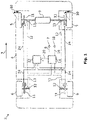
- Fig. 1 shows a schematic view of a vehicle 2 with a basically known driving dynamic control. Details to this driving dynamic control can be taken from DE 10 2011 080 789 A1 .
- the vehicle 2 is movable in a driving direction 3 and comprises a chassis 4 that is in the driving direction 3 movably carried on two front wheels 5 and two rear wheels 6. Each wheel 5, 6 can be slowed down via a brake 8 that is stationary fixed at the chassis 4 to slow down the movement of the vehicle on a street that is not shown in the figures.
- the driving direction 3 during the movement of the vehicle 2 can be controlled by a driver of the vehicle 2 by positioning a steering wheel 7 that is symbolically indicated in Fig. 1 into a steering angle 8.
- the steering wheel 7 itself controls based on the steering angle 8 a steering gear 9 that adjusts a wheel angle 10 of the front wheels 5 based on the steering angle 8.
- the vehicle 2 runs a trajectory on the street that is defined by the driver of the vehicle.
- the vehicle 2 During the movement of the vehicle 2 it may occur in a manner that is basically known to the skilled person in the art that the wheels 5, 6 loose their contact to the street and deviates from the trajectory defined by the driver. To prevent such a behaviour, the vehicle 2 is provided with the before mentioned vehicle dynamic control.
- the vehicle dynamic control includes a brake 11 and wheel speed sensor 12 at each wheel 5, 6.
- the wheel speed sensor 12 measures the wheel speed 13 of each wheel and provides it to a controller 14.
- the controller 14 further receives inertial data 16 like a gear rate of the vehicle 2 from an inertial sensor 18 and calculates based on these data the measured driving direction. Then, the controller 14 determines whether the measured driving direction corresponds to the steering angle 8 defined by the driver. In case of any deviations, the controller 14 outputs a controll signal 20 to a actuator 22 that individually controls the brakes 11 with suitable acutator signals 24 to correct the driving direction 3 of the vehicle.
- the steering wheel 7 When the driver positions the steering wheel 7 in the steering angle 8, the steering wheel 7 turns a steering column 26 around a rotation axis 28 that itself moves a steering rod 30 for turning the front wheels. That is, the rotation angle of the steering column 26 around the rotation axis 28 corresponds to the steering angle 8, such that when the rotation angle of the steering column 26 is measured, the steering angle 8 of the steering wheel 7 is known.
- this steering angle sensor 32 measures the rotation angle of the steering column 26 and therewith the steering angle 8.
- this steering angle sensor 32 should be described in further detail.
- the steering angle sensor 32 comprises an encoder 34 that is stationary to the steering column 26 and a magnet sensor 36 that is stationary to the chassis 4 of the vehicle 2.
- the fixation of these components within the vehicle 2 is indicated by arrows in Figs. 3 to 4b .
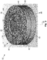
- the encoder 36 is comprises a first magnet 38 and a second magnet 40. Both magnets 38, 40 are formed as a circular disc that is magnetised in a direction perpendicular to the rotation axis, such that one disc half of each magnet 38, 40 is the north pole 42 and the other disc half of each magnet 38, 40 is the south pole 44. Both magnets 38, 40 are stacked on each other and alligned to the rotation axis 28. Therein, the north pole 42 of one magnet 38, 40 is placed on the south pole 44 of the other magnet 40, 38 and vice versa, such that both magnets 38, 40 are displaced in a rotation direction 46 around the rotation axis 28.
- the description of the encoder 32 as composed based on two separated magnets 38, 40 is only figurative to comprehensively explain the construction of the encoder 32.
- the encoder 32 can also be a single magnetizable piece, wherein the north and south poles 42, 44 are introduced with a suitable magnetization method.
- the first magnet 38 has a top surface 48 that is directed to the magnet sensor 36.
- the top surface 48 of the first magnet 38 is not visible in the perspective of Fig. 4b .
- the second magnet 40 is attached to the first magnet 38 opposite to the top surface 48.
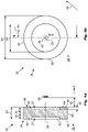
- the encoder 32 Seen from the rotation axis 28, the encoder 32 has a circular shape with an encoder diameter 52 of 11 mm.
- the first magnet 38 of the encoder 32 includes a recess 52 that has seen in the direction of the rotation axis 28 a circular shape with a recess diameter 54 of 7 mm.
- the recess 52 is formed with a recess depth 56 of 0,55 mm, while the complete encoder 32 has seen in the rotational axis 28 an encoder height 58 of 3 mm.
- the second magnet 40 of the encoder 34 also includes a recess 52' that is formed symmetrically into the second magnet 40 with respect to a section plane 60 separating the first magnet 38 from the second magnet 40.
- both magnets have a same magnet thickness 61 in the direction of the rotation axis 28 of 1,5 mm.
- the encoder 34 generates a magnetic field that is not visible in figs. 3 to 4b .
- the magnetic field varies around the rotation axis 28, such that a rotation of the encoder 34 around the rotation axis 28 changes the magnetic field from the view of the magnetic sensor 36. That is, based on the change of the magnetic field, the magnetic sensor 36 can derive the rotation angle of the steering column 26.
- the magnetic sensor 36 is placed in a measurement distance 62 from the top side 48 of the encoder 34.
- This measurement distance 62 however has an impact on an angular error in the rotation angle to be measured.
- the angular error always exists and defines thus a tolerance, by which the magnetic sensor 36 can be placed relatively to the encoder 34.
- fig. 5 shows a diagram, in which a first developing 64 of a maximal angular error 66 and a second developing 68 of a maximal angular error 66 over the measurement distance 62 is drawn. These measurements were taken for a residual induction of 300 mT.
- the first developing 64 belongs to a known angle sensor that is described in DE 10 2018 102 184 .
- the known angle sensor outputs angle results with a comparatively high maximal angular error 66 that rapidly falls with an increasing measurement distance 62 until a minimum error 70 at an optimum distance 72. After this minimum error 70, the maximal angular error 66 raises in the known angle sensor.
- the measurement distance 62 must chosen at the optimum distance 72 and due to the comparatively high non-linearity, there are no high tolerances for relative displacement errors between encoder and magnetic sensor.
- the second developing 68 in turn belongs to the angle sensor 32 according to the present embodiment.
- the measurements clearly show that the maximal angular error 66 in the angle sensor 32 according to the present embodiment keeps below the minimum error 70 for measurement distances 62 in a lower distance range 73 lower than the optimum distance 72. There is even a zero crossing 74 of the maximal angular error 66 indicating that the maximal angular error 66 can be further reduced over the known angle sensor within the lower distance range 73.
- the second developing 68 keeps compared to the first developing 64 comparatively constant in the lower distance range 73. That is, the encoder 34 and the magnetic sensor 36 can be basically arbitrarily placed relative to each other within the lower distance range, without significantly running contrary a required maximal angular error. This freedom can be used in dimension the angle sensor according to the present embodiment with higher tolerances.
Landscapes
- Engineering & Computer Science (AREA)
- Combustion & Propulsion (AREA)
- Transportation (AREA)
- Mechanical Engineering (AREA)
- Chemical & Material Sciences (AREA)
- Physics & Mathematics (AREA)
- General Physics & Mathematics (AREA)
- Electromagnetism (AREA)
- Power Engineering (AREA)
- Measurement Of Length, Angles, Or The Like Using Electric Or Magnetic Means (AREA)
- Transmission And Conversion Of Sensor Element Output (AREA)
- Steering Controls (AREA)
- Regulating Braking Force (AREA)
Priority Applications (8)
| Application Number | Priority Date | Filing Date | Title |
|---|---|---|---|
| ES19163099T ES2927209T3 (es) | 2019-03-15 | 2019-03-15 | Vehículo con sensor de ángulo de dirección |
| HUE19163099A HUE059648T2 (hu) | 2019-03-15 | 2019-03-15 | Kormányzásiszög-érzékelõvel ellátott jármû |
| PL19163099.5T PL3708465T3 (pl) | 2019-03-15 | 2019-03-15 | Pojazd z czujnikiem kąta skrętu |
| EP19163099.5A EP3708465B1 (en) | 2019-03-15 | 2019-03-15 | Vehicle with steering angle sensor |
| CN202010134765.XA CN111688808A (zh) | 2019-03-15 | 2020-03-02 | 带有转向角传感器的车辆 |
| US16/816,628 US11325645B2 (en) | 2019-03-15 | 2020-03-12 | Vehicle with steering angle sensor |
| KR1020200030823A KR20200110222A (ko) | 2019-03-15 | 2020-03-12 | 조향각 센서를 갖는 차량 |
| JP2020044625A JP7485524B2 (ja) | 2019-03-15 | 2020-03-13 | 転舵角センサ搭載車両 |
Applications Claiming Priority (1)
| Application Number | Priority Date | Filing Date | Title |
|---|---|---|---|
| EP19163099.5A EP3708465B1 (en) | 2019-03-15 | 2019-03-15 | Vehicle with steering angle sensor |
Publications (2)
| Publication Number | Publication Date |
|---|---|
| EP3708465A1 EP3708465A1 (en) | 2020-09-16 |
| EP3708465B1 true EP3708465B1 (en) | 2022-06-22 |
Family
ID=65817891
Family Applications (1)
| Application Number | Title | Priority Date | Filing Date |
|---|---|---|---|
| EP19163099.5A Active EP3708465B1 (en) | 2019-03-15 | 2019-03-15 | Vehicle with steering angle sensor |
Country Status (8)
| Country | Link |
|---|---|
| US (1) | US11325645B2 (pl) |
| EP (1) | EP3708465B1 (pl) |
| JP (1) | JP7485524B2 (pl) |
| KR (1) | KR20200110222A (pl) |
| CN (1) | CN111688808A (pl) |
| ES (1) | ES2927209T3 (pl) |
| HU (1) | HUE059648T2 (pl) |
| PL (1) | PL3708465T3 (pl) |
Families Citing this family (1)
| Publication number | Priority date | Publication date | Assignee | Title |
|---|---|---|---|---|
| FR3121117B1 (fr) | 2021-03-29 | 2025-06-27 | Psa Automobiles Sa | Véhicule automobile avec structure arrière renforcée |
Family Cites Families (23)
| Publication number | Priority date | Publication date | Assignee | Title |
|---|---|---|---|---|
| JPH0325109U (pl) * | 1989-07-20 | 1991-03-14 | ||
| DE19703903A1 (de) * | 1997-02-03 | 1998-08-13 | Bosch Gmbh Robert | Lenkwinkelsensor |
| JP2000269567A (ja) * | 1999-03-18 | 2000-09-29 | Tdk Corp | 半導体磁気抵抗素子 |
| AU5473000A (en) | 1999-06-28 | 2001-01-31 | American Electronic Components | Linear displacement sensor |
| JP2002022406A (ja) * | 2000-07-11 | 2002-01-23 | Yazaki Corp | 回転角センサ |
| DE102005007307A1 (de) | 2005-02-16 | 2006-08-17 | Zf Lenksysteme Gmbh | Lenkung |
| US7304472B2 (en) * | 2005-04-28 | 2007-12-04 | Williams Controls Industries, Inc. | Rotary position sensor |
| DE102008047109A1 (de) * | 2007-09-13 | 2009-05-14 | Marquardt Gmbh | Drehwinkelsensor |
| DE102008040360A1 (de) * | 2008-07-11 | 2010-01-14 | Robert Bosch Gmbh | Einrichtung zur Erfassung eines rotierenden Magnetfelds |
| FR2936307B1 (fr) * | 2008-09-24 | 2010-09-17 | Moving Magnet Tech Mmt | Capteur de position lineaire ou rotatifa aimant permanent pour la detection d'une cible ferromagnetique |
| JP2010145371A (ja) * | 2008-12-22 | 2010-07-01 | Aisin Seiki Co Ltd | 角度検出装置 |
| DE102010033769A1 (de) * | 2010-08-09 | 2012-02-09 | Valeo Schalter Und Sensoren Gmbh | Vorrichtung mit einem Drehmomentsensor und einem Drehwinkelsensor |
| DE102011080789B4 (de) | 2010-08-10 | 2022-11-10 | Continental Automotive Technologies GmbH | Verfahren und System zur Regelung der Fahrstabilität |
| JP5141780B2 (ja) | 2011-01-12 | 2013-02-13 | Tdk株式会社 | 回転角度センサ |
| JP5607594B2 (ja) * | 2011-09-12 | 2014-10-15 | 株式会社東海理化電機製作所 | ポジションセンサ |
| DE102013015452A1 (de) * | 2013-09-18 | 2015-03-19 | Valeo Schalter Und Sensoren Gmbh | Verfahren zum Herstellen einer Magneteinheit für eine Sensoreinrichtung zum Erfassen einer einen Rotationszustand einer Lenkwelle eines Kraftfahrzeugs charakterisierenden Messgröße, Magneteinheit, Sensoreinrichtung und Kraftfahrzeug |
| DE102014200365A1 (de) * | 2013-11-26 | 2015-05-28 | Continental Teves Ag & Co. Ohg | Sensoranordnung und Magnetisierungsvorrichtung sowie Verwendung der Sensoranordnung in einem Kraftfahrzeugsteuergerät |
| JP6148971B2 (ja) | 2013-12-02 | 2017-06-14 | 日立オートモティブシステムズ株式会社 | 回転角検出装置 |
| DE102014207139A1 (de) * | 2014-04-14 | 2015-10-15 | Robert Bosch Gmbh | Messvorrichtung für eine berührungslose Drehwinkelerfassung |
| DE102016009209B3 (de) * | 2016-08-01 | 2017-10-19 | Tdk-Micronas Gmbh | Messsystem |
| DE102017103877A1 (de) * | 2017-02-24 | 2018-08-30 | Infineon Technologies Ag | Magnetsensoranordnung und magnetisches Erfassungsverfahren |
| DE102017003075B4 (de) * | 2017-03-30 | 2021-09-23 | Tdk-Micronas Gmbh | Messsystem zur Drehwinkelbestimmung |
| JP2019131176A (ja) * | 2018-01-31 | 2019-08-08 | ボーンズ・インコーポレーテッドBourns,Incorporated | スロット付磁石を有する車両 |
-
2019
- 2019-03-15 HU HUE19163099A patent/HUE059648T2/hu unknown
- 2019-03-15 ES ES19163099T patent/ES2927209T3/es active Active
- 2019-03-15 PL PL19163099.5T patent/PL3708465T3/pl unknown
- 2019-03-15 EP EP19163099.5A patent/EP3708465B1/en active Active
-
2020
- 2020-03-02 CN CN202010134765.XA patent/CN111688808A/zh active Pending
- 2020-03-12 KR KR1020200030823A patent/KR20200110222A/ko not_active Ceased
- 2020-03-12 US US16/816,628 patent/US11325645B2/en active Active
- 2020-03-13 JP JP2020044625A patent/JP7485524B2/ja active Active
Also Published As
| Publication number | Publication date |
|---|---|
| US20200290676A1 (en) | 2020-09-17 |
| CN111688808A (zh) | 2020-09-22 |
| ES2927209T3 (es) | 2022-11-03 |
| JP2020147279A (ja) | 2020-09-17 |
| EP3708465A1 (en) | 2020-09-16 |
| US11325645B2 (en) | 2022-05-10 |
| JP7485524B2 (ja) | 2024-05-16 |
| PL3708465T3 (pl) | 2022-11-21 |
| KR20200110222A (ko) | 2020-09-23 |
| HUE059648T2 (hu) | 2022-12-28 |
Similar Documents
| Publication | Publication Date | Title |
|---|---|---|
| CN102686980B (zh) | 用于检测运动元件位移的磁场传感器装置 | |
| US20100289485A1 (en) | System including a magnet and first and second concentrators | |
| JP5296541B2 (ja) | 車両のための電動補助駆動装置 | |
| US20150211890A1 (en) | Sensor Arrangement for Detecting Angles of Rotation on a Rotated Component | |
| WO2009120507A3 (en) | Position measurement using magnetic fields | |
| KR20140078047A (ko) | 모터 및 그의 센싱 마그네트 | |
| EP1561608B1 (en) | Pressure sensing device for rotatable parts and pressure detection method therefor | |
| US10953919B2 (en) | Steering angle sensor with slotted magnet | |
| EP3708465B1 (en) | Vehicle with steering angle sensor | |
| CN103419889A (zh) | 一种电动助力自行车的助力控制机构 | |
| KR20070110353A (ko) | 회전 가능 부재의 회전각을 무접촉 방식으로 검출하는 방법및 장치 | |
| JP2013082440A (ja) | ステアリング装置 | |
| JP2005062189A (ja) | 磁気多極エンコーダ | |
| JP2003307419A (ja) | 舵角検出装置 | |
| JP2002090109A (ja) | 回転角検出装置、トルク検出装置、及び舵取装置 | |
| CN206412855U (zh) | 带编码器的轮毂电机 | |
| JPH03137530A (ja) | 変位センサ及びトルクセンサ | |
| JP2010014462A (ja) | 回転トルク検出装置 | |
| EP4227645B1 (en) | System for measuring the rotation of a vehicle throttle knob | |
| US12534152B2 (en) | Devices and methods for controlling the power of a vehicle motor | |
| JP2014065367A (ja) | 回転角度・トルク検出装置 | |
| JP2011043398A (ja) | 回転トルク検出装置 | |
| CN102473019A (zh) | 踏板单元、用于检测踏板运动的无接触的传感机构、输出装置、传感器元件以及用于制造踏板单元的方法 | |
| JP2024084478A (ja) | ストロークセンサとこれを備えたストロークセンサ組立体 | |
| JPH07107706A (ja) | サーボモータ |
Legal Events
| Date | Code | Title | Description |
|---|---|---|---|
| PUAI | Public reference made under article 153(3) epc to a published international application that has entered the european phase |
Free format text: ORIGINAL CODE: 0009012 |
|
| STAA | Information on the status of an ep patent application or granted ep patent |
Free format text: STATUS: THE APPLICATION HAS BEEN PUBLISHED |
|
| AK | Designated contracting states |
Kind code of ref document: A1 Designated state(s): AL AT BE BG CH CY CZ DE DK EE ES FI FR GB GR HR HU IE IS IT LI LT LU LV MC MK MT NL NO PL PT RO RS SE SI SK SM TR |
|
| AX | Request for extension of the european patent |
Extension state: BA ME |
|
| STAA | Information on the status of an ep patent application or granted ep patent |
Free format text: STATUS: REQUEST FOR EXAMINATION WAS MADE |
|
| 17P | Request for examination filed |
Effective date: 20210316 |
|
| RBV | Designated contracting states (corrected) |
Designated state(s): AL AT BE BG CH CY CZ DE DK EE ES FI FR GB GR HR HU IE IS IT LI LT LU LV MC MK MT NL NO PL PT RO RS SE SI SK SM TR |
|
| GRAP | Despatch of communication of intention to grant a patent |
Free format text: ORIGINAL CODE: EPIDOSNIGR1 |
|
| STAA | Information on the status of an ep patent application or granted ep patent |
Free format text: STATUS: GRANT OF PATENT IS INTENDED |
|
| INTG | Intention to grant announced |
Effective date: 20220128 |
|
| RAP3 | Party data changed (applicant data changed or rights of an application transferred) |
Owner name: BOURNS, INC. |
|
| GRAS | Grant fee paid |
Free format text: ORIGINAL CODE: EPIDOSNIGR3 |
|
| GRAA | (expected) grant |
Free format text: ORIGINAL CODE: 0009210 |
|
| STAA | Information on the status of an ep patent application or granted ep patent |
Free format text: STATUS: THE PATENT HAS BEEN GRANTED |
|
| AK | Designated contracting states |
Kind code of ref document: B1 Designated state(s): AL AT BE BG CH CY CZ DE DK EE ES FI FR GB GR HR HU IE IS IT LI LT LU LV MC MK MT NL NO PL PT RO RS SE SI SK SM TR |
|
| REG | Reference to a national code |
Ref country code: GB Ref legal event code: FG4D |
|
| REG | Reference to a national code |
Ref country code: CH Ref legal event code: EP |
|
| REG | Reference to a national code |
Ref country code: DE Ref legal event code: R096 Ref document number: 602019016055 Country of ref document: DE |
|
| REG | Reference to a national code |
Ref country code: AT Ref legal event code: REF Ref document number: 1499615 Country of ref document: AT Kind code of ref document: T Effective date: 20220715 |
|
| REG | Reference to a national code |
Ref country code: IE Ref legal event code: FG4D |
|
| REG | Reference to a national code |
Ref country code: RO Ref legal event code: EPE |
|
| REG | Reference to a national code |
Ref country code: LT Ref legal event code: MG9D |
|
| REG | Reference to a national code |
Ref country code: NL Ref legal event code: MP Effective date: 20220622 |
|
| PG25 | Lapsed in a contracting state [announced via postgrant information from national office to epo] |
Ref country code: SE Free format text: LAPSE BECAUSE OF FAILURE TO SUBMIT A TRANSLATION OF THE DESCRIPTION OR TO PAY THE FEE WITHIN THE PRESCRIBED TIME-LIMIT Effective date: 20220622 Ref country code: NO Free format text: LAPSE BECAUSE OF FAILURE TO SUBMIT A TRANSLATION OF THE DESCRIPTION OR TO PAY THE FEE WITHIN THE PRESCRIBED TIME-LIMIT Effective date: 20220922 Ref country code: LT Free format text: LAPSE BECAUSE OF FAILURE TO SUBMIT A TRANSLATION OF THE DESCRIPTION OR TO PAY THE FEE WITHIN THE PRESCRIBED TIME-LIMIT Effective date: 20220622 Ref country code: HR Free format text: LAPSE BECAUSE OF FAILURE TO SUBMIT A TRANSLATION OF THE DESCRIPTION OR TO PAY THE FEE WITHIN THE PRESCRIBED TIME-LIMIT Effective date: 20220622 Ref country code: GR Free format text: LAPSE BECAUSE OF FAILURE TO SUBMIT A TRANSLATION OF THE DESCRIPTION OR TO PAY THE FEE WITHIN THE PRESCRIBED TIME-LIMIT Effective date: 20220923 Ref country code: FI Free format text: LAPSE BECAUSE OF FAILURE TO SUBMIT A TRANSLATION OF THE DESCRIPTION OR TO PAY THE FEE WITHIN THE PRESCRIBED TIME-LIMIT Effective date: 20220622 Ref country code: BG Free format text: LAPSE BECAUSE OF FAILURE TO SUBMIT A TRANSLATION OF THE DESCRIPTION OR TO PAY THE FEE WITHIN THE PRESCRIBED TIME-LIMIT Effective date: 20220922 |
|
| REG | Reference to a national code |
Ref country code: ES Ref legal event code: FG2A Ref document number: 2927209 Country of ref document: ES Kind code of ref document: T3 Effective date: 20221103 |
|
| REG | Reference to a national code |
Ref country code: AT Ref legal event code: MK05 Ref document number: 1499615 Country of ref document: AT Kind code of ref document: T Effective date: 20220622 |
|
| PG25 | Lapsed in a contracting state [announced via postgrant information from national office to epo] |
Ref country code: RS Free format text: LAPSE BECAUSE OF FAILURE TO SUBMIT A TRANSLATION OF THE DESCRIPTION OR TO PAY THE FEE WITHIN THE PRESCRIBED TIME-LIMIT Effective date: 20220622 Ref country code: LV Free format text: LAPSE BECAUSE OF FAILURE TO SUBMIT A TRANSLATION OF THE DESCRIPTION OR TO PAY THE FEE WITHIN THE PRESCRIBED TIME-LIMIT Effective date: 20220622 |
|
| REG | Reference to a national code |
Ref country code: HU Ref legal event code: AG4A Ref document number: E059648 Country of ref document: HU |
|
| PG25 | Lapsed in a contracting state [announced via postgrant information from national office to epo] |
Ref country code: NL Free format text: LAPSE BECAUSE OF FAILURE TO SUBMIT A TRANSLATION OF THE DESCRIPTION OR TO PAY THE FEE WITHIN THE PRESCRIBED TIME-LIMIT Effective date: 20220622 |
|
| PG25 | Lapsed in a contracting state [announced via postgrant information from national office to epo] |
Ref country code: SM Free format text: LAPSE BECAUSE OF FAILURE TO SUBMIT A TRANSLATION OF THE DESCRIPTION OR TO PAY THE FEE WITHIN THE PRESCRIBED TIME-LIMIT Effective date: 20220622 Ref country code: SK Free format text: LAPSE BECAUSE OF FAILURE TO SUBMIT A TRANSLATION OF THE DESCRIPTION OR TO PAY THE FEE WITHIN THE PRESCRIBED TIME-LIMIT Effective date: 20220622 Ref country code: PT Free format text: LAPSE BECAUSE OF FAILURE TO SUBMIT A TRANSLATION OF THE DESCRIPTION OR TO PAY THE FEE WITHIN THE PRESCRIBED TIME-LIMIT Effective date: 20221024 Ref country code: EE Free format text: LAPSE BECAUSE OF FAILURE TO SUBMIT A TRANSLATION OF THE DESCRIPTION OR TO PAY THE FEE WITHIN THE PRESCRIBED TIME-LIMIT Effective date: 20220622 Ref country code: AT Free format text: LAPSE BECAUSE OF FAILURE TO SUBMIT A TRANSLATION OF THE DESCRIPTION OR TO PAY THE FEE WITHIN THE PRESCRIBED TIME-LIMIT Effective date: 20220622 |
|
| PG25 | Lapsed in a contracting state [announced via postgrant information from national office to epo] |
Ref country code: IS Free format text: LAPSE BECAUSE OF FAILURE TO SUBMIT A TRANSLATION OF THE DESCRIPTION OR TO PAY THE FEE WITHIN THE PRESCRIBED TIME-LIMIT Effective date: 20221022 |
|
| REG | Reference to a national code |
Ref country code: DE Ref legal event code: R097 Ref document number: 602019016055 Country of ref document: DE |
|
| PG25 | Lapsed in a contracting state [announced via postgrant information from national office to epo] |
Ref country code: AL Free format text: LAPSE BECAUSE OF FAILURE TO SUBMIT A TRANSLATION OF THE DESCRIPTION OR TO PAY THE FEE WITHIN THE PRESCRIBED TIME-LIMIT Effective date: 20220622 |
|
| PG25 | Lapsed in a contracting state [announced via postgrant information from national office to epo] |
Ref country code: DK Free format text: LAPSE BECAUSE OF FAILURE TO SUBMIT A TRANSLATION OF THE DESCRIPTION OR TO PAY THE FEE WITHIN THE PRESCRIBED TIME-LIMIT Effective date: 20220622 |
|
| PLBE | No opposition filed within time limit |
Free format text: ORIGINAL CODE: 0009261 |
|
| STAA | Information on the status of an ep patent application or granted ep patent |
Free format text: STATUS: NO OPPOSITION FILED WITHIN TIME LIMIT |
|
| 26N | No opposition filed |
Effective date: 20230323 |
|
| P01 | Opt-out of the competence of the unified patent court (upc) registered |
Effective date: 20230529 |
|
| PG25 | Lapsed in a contracting state [announced via postgrant information from national office to epo] |
Ref country code: SI Free format text: LAPSE BECAUSE OF FAILURE TO SUBMIT A TRANSLATION OF THE DESCRIPTION OR TO PAY THE FEE WITHIN THE PRESCRIBED TIME-LIMIT Effective date: 20220622 |
|
| PG25 | Lapsed in a contracting state [announced via postgrant information from national office to epo] |
Ref country code: MC Free format text: LAPSE BECAUSE OF FAILURE TO SUBMIT A TRANSLATION OF THE DESCRIPTION OR TO PAY THE FEE WITHIN THE PRESCRIBED TIME-LIMIT Effective date: 20220622 |
|
| REG | Reference to a national code |
Ref country code: CH Ref legal event code: PL |
|
| GBPC | Gb: european patent ceased through non-payment of renewal fee |
Effective date: 20230315 |
|
| REG | Reference to a national code |
Ref country code: BE Ref legal event code: MM Effective date: 20230331 |
|
| PG25 | Lapsed in a contracting state [announced via postgrant information from national office to epo] |
Ref country code: LU Free format text: LAPSE BECAUSE OF NON-PAYMENT OF DUE FEES Effective date: 20230315 |
|
| REG | Reference to a national code |
Ref country code: IE Ref legal event code: MM4A |
|
| PG25 | Lapsed in a contracting state [announced via postgrant information from national office to epo] |
Ref country code: GB Free format text: LAPSE BECAUSE OF NON-PAYMENT OF DUE FEES Effective date: 20230315 |
|
| PG25 | Lapsed in a contracting state [announced via postgrant information from national office to epo] |
Ref country code: LI Free format text: LAPSE BECAUSE OF NON-PAYMENT OF DUE FEES Effective date: 20230331 Ref country code: IE Free format text: LAPSE BECAUSE OF NON-PAYMENT OF DUE FEES Effective date: 20230315 Ref country code: GB Free format text: LAPSE BECAUSE OF NON-PAYMENT OF DUE FEES Effective date: 20230315 Ref country code: CH Free format text: LAPSE BECAUSE OF NON-PAYMENT OF DUE FEES Effective date: 20230331 |
|
| PG25 | Lapsed in a contracting state [announced via postgrant information from national office to epo] |
Ref country code: BE Free format text: LAPSE BECAUSE OF NON-PAYMENT OF DUE FEES Effective date: 20230331 |
|
| PGFP | Annual fee paid to national office [announced via postgrant information from national office to epo] |
Ref country code: RO Payment date: 20240306 Year of fee payment: 6 Ref country code: HU Payment date: 20240318 Year of fee payment: 6 Ref country code: DE Payment date: 20240307 Year of fee payment: 6 Ref country code: CZ Payment date: 20240301 Year of fee payment: 6 |
|
| PGFP | Annual fee paid to national office [announced via postgrant information from national office to epo] |
Ref country code: PL Payment date: 20240306 Year of fee payment: 6 Ref country code: IT Payment date: 20240329 Year of fee payment: 6 Ref country code: FR Payment date: 20240308 Year of fee payment: 6 |
|
| PGFP | Annual fee paid to national office [announced via postgrant information from national office to epo] |
Ref country code: ES Payment date: 20240403 Year of fee payment: 6 |
|
| PG25 | Lapsed in a contracting state [announced via postgrant information from national office to epo] |
Ref country code: BG Free format text: LAPSE BECAUSE OF FAILURE TO SUBMIT A TRANSLATION OF THE DESCRIPTION OR TO PAY THE FEE WITHIN THE PRESCRIBED TIME-LIMIT Effective date: 20220622 |
|
| PG25 | Lapsed in a contracting state [announced via postgrant information from national office to epo] |
Ref country code: BG Free format text: LAPSE BECAUSE OF FAILURE TO SUBMIT A TRANSLATION OF THE DESCRIPTION OR TO PAY THE FEE WITHIN THE PRESCRIBED TIME-LIMIT Effective date: 20220622 |
|
| PG25 | Lapsed in a contracting state [announced via postgrant information from national office to epo] |
Ref country code: CY Free format text: LAPSE BECAUSE OF FAILURE TO SUBMIT A TRANSLATION OF THE DESCRIPTION OR TO PAY THE FEE WITHIN THE PRESCRIBED TIME-LIMIT; INVALID AB INITIO Effective date: 20190315 |
|
| REG | Reference to a national code |
Ref country code: DE Ref legal event code: R119 Ref document number: 602019016055 Country of ref document: DE |
|
| PG25 | Lapsed in a contracting state [announced via postgrant information from national office to epo] |
Ref country code: CZ Free format text: LAPSE BECAUSE OF NON-PAYMENT OF DUE FEES Effective date: 20250315 |
|
| PG25 | Lapsed in a contracting state [announced via postgrant information from national office to epo] |
Ref country code: RO Free format text: LAPSE BECAUSE OF NON-PAYMENT OF DUE FEES Effective date: 20250315 |
|
| PG25 | Lapsed in a contracting state [announced via postgrant information from national office to epo] |
Ref country code: HU Free format text: LAPSE BECAUSE OF NON-PAYMENT OF DUE FEES Effective date: 20250316 |
|
| PG25 | Lapsed in a contracting state [announced via postgrant information from national office to epo] |
Ref country code: TR Free format text: LAPSE BECAUSE OF FAILURE TO SUBMIT A TRANSLATION OF THE DESCRIPTION OR TO PAY THE FEE WITHIN THE PRESCRIBED TIME-LIMIT Effective date: 20220622 |
|
| PG25 | Lapsed in a contracting state [announced via postgrant information from national office to epo] |
Ref country code: DE Free format text: LAPSE BECAUSE OF NON-PAYMENT OF DUE FEES Effective date: 20251001 |
|
| PG25 | Lapsed in a contracting state [announced via postgrant information from national office to epo] |
Ref country code: IT Free format text: LAPSE BECAUSE OF NON-PAYMENT OF DUE FEES Effective date: 20250315 Ref country code: FR Free format text: LAPSE BECAUSE OF NON-PAYMENT OF DUE FEES Effective date: 20250331 |
|
| PG25 | Lapsed in a contracting state [announced via postgrant information from national office to epo] |
Ref country code: PL Free format text: LAPSE BECAUSE OF NON-PAYMENT OF DUE FEES Effective date: 20250315 |
|
| REG | Reference to a national code |
Ref country code: ES Ref legal event code: FD2A Effective date: 20260428 |