EP3710196B1 - Laser machining system and method for laser machining - Google Patents
Laser machining system and method for laser machining Download PDFInfo
- Publication number
- EP3710196B1 EP3710196B1 EP18789601.4A EP18789601A EP3710196B1 EP 3710196 B1 EP3710196 B1 EP 3710196B1 EP 18789601 A EP18789601 A EP 18789601A EP 3710196 B1 EP3710196 B1 EP 3710196B1
- Authority
- EP
- European Patent Office
- Prior art keywords
- laser
- machining
- laser beam
- seam
- measuring
- Prior art date
- Legal status (The legal status is an assumption and is not a legal conclusion. Google has not performed a legal analysis and makes no representation as to the accuracy of the status listed.)
- Active
Links
Images


Classifications
-
- G—PHYSICS
- G01—MEASURING; TESTING
- G01B—MEASURING LENGTH, THICKNESS OR SIMILAR LINEAR DIMENSIONS; MEASURING ANGLES; MEASURING AREAS; MEASURING IRREGULARITIES OF SURFACES OR CONTOURS
- G01B9/00—Measuring instruments characterised by the use of optical techniques
- G01B9/02—Interferometers
- G01B9/0209—Low-coherence interferometers
- G01B9/02091—Tomographic interferometers, e.g. based on optical coherence
-
- B—PERFORMING OPERATIONS; TRANSPORTING
- B23—MACHINE TOOLS; METAL-WORKING NOT OTHERWISE PROVIDED FOR
- B23K—SOLDERING OR UNSOLDERING; WELDING; CLADDING OR PLATING BY SOLDERING OR WELDING; CUTTING BY APPLYING HEAT LOCALLY, e.g. FLAME CUTTING; WORKING BY LASER BEAM
- B23K26/00—Working by laser beam, e.g. welding, cutting or boring
- B23K26/02—Positioning or observing the workpiece, e.g. with respect to the point of impact; Aligning, aiming or focusing the laser beam
- B23K26/03—Observing, e.g. monitoring, the workpiece
- B23K26/032—Observing, e.g. monitoring, the workpiece using optical means
-
- B—PERFORMING OPERATIONS; TRANSPORTING
- B23—MACHINE TOOLS; METAL-WORKING NOT OTHERWISE PROVIDED FOR
- B23K—SOLDERING OR UNSOLDERING; WELDING; CLADDING OR PLATING BY SOLDERING OR WELDING; CUTTING BY APPLYING HEAT LOCALLY, e.g. FLAME CUTTING; WORKING BY LASER BEAM
- B23K26/00—Working by laser beam, e.g. welding, cutting or boring
- B23K26/02—Positioning or observing the workpiece, e.g. with respect to the point of impact; Aligning, aiming or focusing the laser beam
- B23K26/04—Automatically aligning, aiming or focusing the laser beam, e.g. using the back-scattered light
- B23K26/044—Seam tracking
-
- B—PERFORMING OPERATIONS; TRANSPORTING
- B23—MACHINE TOOLS; METAL-WORKING NOT OTHERWISE PROVIDED FOR
- B23K—SOLDERING OR UNSOLDERING; WELDING; CLADDING OR PLATING BY SOLDERING OR WELDING; CUTTING BY APPLYING HEAT LOCALLY, e.g. FLAME CUTTING; WORKING BY LASER BEAM
- B23K26/00—Working by laser beam, e.g. welding, cutting or boring
- B23K26/02—Positioning or observing the workpiece, e.g. with respect to the point of impact; Aligning, aiming or focusing the laser beam
- B23K26/06—Shaping the laser beam, e.g. by masks or multi-focusing
- B23K26/064—Shaping the laser beam, e.g. by masks or multi-focusing by means of optical elements, e.g. lenses, mirrors or prisms
- B23K26/0643—Shaping the laser beam, e.g. by masks or multi-focusing by means of optical elements, e.g. lenses, mirrors or prisms comprising mirrors
-
- B—PERFORMING OPERATIONS; TRANSPORTING
- B23—MACHINE TOOLS; METAL-WORKING NOT OTHERWISE PROVIDED FOR
- B23K—SOLDERING OR UNSOLDERING; WELDING; CLADDING OR PLATING BY SOLDERING OR WELDING; CUTTING BY APPLYING HEAT LOCALLY, e.g. FLAME CUTTING; WORKING BY LASER BEAM
- B23K26/00—Working by laser beam, e.g. welding, cutting or boring
- B23K26/02—Positioning or observing the workpiece, e.g. with respect to the point of impact; Aligning, aiming or focusing the laser beam
- B23K26/06—Shaping the laser beam, e.g. by masks or multi-focusing
- B23K26/064—Shaping the laser beam, e.g. by masks or multi-focusing by means of optical elements, e.g. lenses, mirrors or prisms
- B23K26/0648—Shaping the laser beam, e.g. by masks or multi-focusing by means of optical elements, e.g. lenses, mirrors or prisms comprising lenses
-
- B—PERFORMING OPERATIONS; TRANSPORTING
- B23—MACHINE TOOLS; METAL-WORKING NOT OTHERWISE PROVIDED FOR
- B23K—SOLDERING OR UNSOLDERING; WELDING; CLADDING OR PLATING BY SOLDERING OR WELDING; CUTTING BY APPLYING HEAT LOCALLY, e.g. FLAME CUTTING; WORKING BY LASER BEAM
- B23K26/00—Working by laser beam, e.g. welding, cutting or boring
- B23K26/02—Positioning or observing the workpiece, e.g. with respect to the point of impact; Aligning, aiming or focusing the laser beam
- B23K26/06—Shaping the laser beam, e.g. by masks or multi-focusing
- B23K26/064—Shaping the laser beam, e.g. by masks or multi-focusing by means of optical elements, e.g. lenses, mirrors or prisms
- B23K26/0652—Shaping the laser beam, e.g. by masks or multi-focusing by means of optical elements, e.g. lenses, mirrors or prisms comprising prisms
-
- B—PERFORMING OPERATIONS; TRANSPORTING
- B23—MACHINE TOOLS; METAL-WORKING NOT OTHERWISE PROVIDED FOR
- B23K—SOLDERING OR UNSOLDERING; WELDING; CLADDING OR PLATING BY SOLDERING OR WELDING; CUTTING BY APPLYING HEAT LOCALLY, e.g. FLAME CUTTING; WORKING BY LASER BEAM
- B23K26/00—Working by laser beam, e.g. welding, cutting or boring
- B23K26/02—Positioning or observing the workpiece, e.g. with respect to the point of impact; Aligning, aiming or focusing the laser beam
- B23K26/06—Shaping the laser beam, e.g. by masks or multi-focusing
- B23K26/067—Dividing the beam into multiple beams, e.g. multi-focusing
-
- B—PERFORMING OPERATIONS; TRANSPORTING
- B23—MACHINE TOOLS; METAL-WORKING NOT OTHERWISE PROVIDED FOR
- B23K—SOLDERING OR UNSOLDERING; WELDING; CLADDING OR PLATING BY SOLDERING OR WELDING; CUTTING BY APPLYING HEAT LOCALLY, e.g. FLAME CUTTING; WORKING BY LASER BEAM
- B23K26/00—Working by laser beam, e.g. welding, cutting or boring
- B23K26/08—Devices involving relative movement between laser beam and workpiece
- B23K26/082—Scanning systems, i.e. devices involving movement of the laser beam relative to the laser head
-
- B—PERFORMING OPERATIONS; TRANSPORTING
- B23—MACHINE TOOLS; METAL-WORKING NOT OTHERWISE PROVIDED FOR
- B23K—SOLDERING OR UNSOLDERING; WELDING; CLADDING OR PLATING BY SOLDERING OR WELDING; CUTTING BY APPLYING HEAT LOCALLY, e.g. FLAME CUTTING; WORKING BY LASER BEAM
- B23K26/00—Working by laser beam, e.g. welding, cutting or boring
- B23K26/20—Bonding
- B23K26/21—Bonding by welding
- B23K26/24—Seam welding
- B23K26/28—Seam welding of curved planar seams
-
- B—PERFORMING OPERATIONS; TRANSPORTING
- B23—MACHINE TOOLS; METAL-WORKING NOT OTHERWISE PROVIDED FOR
- B23K—SOLDERING OR UNSOLDERING; WELDING; CLADDING OR PLATING BY SOLDERING OR WELDING; CUTTING BY APPLYING HEAT LOCALLY, e.g. FLAME CUTTING; WORKING BY LASER BEAM
- B23K31/00—Processes relevant to this subclass, specially adapted for particular articles or purposes, but not covered by any single one of main groups B23K1/00 - B23K28/00
- B23K31/12—Processes relevant to this subclass, specially adapted for particular articles or purposes, but not covered by any single one of main groups B23K1/00 - B23K28/00 relating to investigating the properties, e.g. the weldability, of materials
- B23K31/125—Weld quality monitoring
-
- G—PHYSICS
- G01—MEASURING; TESTING
- G01B—MEASURING LENGTH, THICKNESS OR SIMILAR LINEAR DIMENSIONS; MEASURING ANGLES; MEASURING AREAS; MEASURING IRREGULARITIES OF SURFACES OR CONTOURS
- G01B2290/00—Aspects of interferometers not specifically covered by any group under G01B9/02
- G01B2290/65—Spatial scanning object beam
Definitions
- the present disclosure relates to a laser processing system, in particular a system for material processing by means of a laser beam, such as a laser processing head for laser welding or laser cutting, and a method for laser processing.
- a laser processing system in particular a system for material processing by means of a laser beam, such as a laser processing head for laser welding or laser cutting, and a method for laser processing.
- the present disclosure relates in particular to seam measurement and seam tracking, for example by means of optical coherence tomography.
- the laser beam emerging from a laser light source is focused on the workpiece to be processed with the aid of beam guidance and focusing optics.
- a laser processing head with collimator optics and focusing optics is used as standard, the laser light being supplied via an optical fiber, also referred to as a laser source.
- the laser light passes through a large number of optical elements, such as lenses, in a device for processing materials by means of a laser, for example in a laser processing head.
- DE 10 2009 057 209 B4 is a device for material processing by means of laser with a scanner optics that can be moved by a guide machine relative to the workpiece to be processed.
- the device comprises a projector which is used to project measuring light in the form of measuring structures onto the workpiece to be processed, and an image sensor which is sensitive in the wavelength range of the measuring light emitted by the projector.
- the projector and the image sensor are connected to the scanner optics and are consequently moved along with the scanner optics when the device is operated. A direction-independent measurement is therefore not possible.
- a laser processing system comprises a first deflection optics which are set up to deflect a processing laser beam in two spatial directions, a second Deflection optics that are set up to deflect a measuring beam independently of the machining laser beam in two spatial directions, and a coupling device that is arranged in a beam path of the machining laser beam and is set up to couple the measuring beam into the beam path of the machining laser beam.
- the first deflecting optics preferably comprises two first deflecting mirrors that are independent of one another.
- the first deflection optics are typically set up for a two-dimensional oscillation of the processing laser beam, such as a movement along a line, preferably along a line perpendicular to the seam path, a circular movement or a movement in the form of an “8”.
- the second deflecting optics preferably comprises two second deflecting mirrors that are independent of one another.
- the second deflection optics is set up for a linear movement and / or a circular movement of the measuring beam.
- the second deflection optics are preferably set up to direct the measuring beam onto at least one workpiece, and in particular onto a joining area of two workpieces, independently of a feed direction of the machining laser beam.
- the coupling device is preferably a beam splitter.
- the coupling device is typically set up to superimpose the machining laser beam and the measuring beam essentially coaxially.
- the laser processing system preferably comprises a controller which is set up to control the first deflection device in such a way that the processing laser beam follows a seam path on the workpiece.
- the laser processing system preferably comprises an evaluation unit which is set up to measure a seam course, such as an edge course and / or a weld seam course, on the workpiece with the measuring beam.
- the evaluation unit can measure an edge profile of joining pieces before the machining laser beam and / or a weld seam profile after the machining laser beam.
- the evaluation unit can in particular be set up to determine the course of the seam by means of optical short coherence tomography.
- a method for laser machining comprises deflecting a machining laser beam in two spatial directions so that the machining laser beam executes a two-dimensional movement on at least one workpiece, deflecting a measuring beam in two spatial directions independently of the machining laser beam, and coupling the measuring beam into a beam path of the machining laser beam.
- the machining laser beam preferably executes an oscillating movement (2D wobbling process), such as, for example, a linear movement, a circular movement or a movement in the form of an “8”.
- 2D wobbling process such as, for example, a linear movement, a circular movement or a movement in the form of an “8”.
- the measuring beam preferably executes a linear or circular movement on the course of the seam, such as on an edge course and / or a weld seam course.
- the method preferably further comprises determining a seam course, such as an edge course of two workpieces to be joined, using the measuring beam, and following the seam course with the processing laser beam based on the determined seam course.
- a seam course such as an edge course of two workpieces to be joined
- Optical short coherence tomography is preferably used to determine the course of the seam.
- a direction-independent measurement of a seam course on a component and an exact positioning of the laser beam at the determined seam position are made possible in a laser machining process.
- An optical measuring beam is guided via its own actuator system and coupled into its beam path via a coupling device after the actuator system of a processing laser and superimposed on it.
- This arrangement enables a quasi-coaxial measurement of the component geometry around the current position of the machining laser beam, regardless of the movement of the machining laser beam during the machining process.
- Another advantage of the embodiments described here for finding seams compared to line projection in the light section method is the resolution that can be achieved.
- the embodiments described here in particular when using optical coherence tomography, offer an accuracy for the measured distance value of approximately 1 ⁇ m. Vertical structures on the component, such as the edge height of a fillet weld, can be measured with this accuracy.
- the resolution that can be achieved with a light section method is mainly limited by the quality of the line projection. Typical line widths are in the range from about 20 to 100 ⁇ m. As a result, the resolution of the structure recognition through the evaluation of the lines on the camera images is about an order of magnitude lower.
- Figure 1 shows a laser processing system 100, and in particular a system for material processing by means of a laser beam, for example for laser welding, according to embodiments of the present disclosure.
- the beam path of the machining laser is shown schematically, and on the right the beam path of the optical sensor system.
- the optical sensor system can be a coherence interferometer.
- the laser processing system 100 comprises first deflection optics 110, which are set up to deflect a machining laser beam 10 in two spatial directions x, y, a second deflection optics 120, which are set up to a measuring beam 15 (sensor beam) independently of the machining laser beam 10 in deflect two spatial directions x, y, and a coupling device 130 which is arranged in a beam path of the processing laser beam 10 and is set up to couple the measuring beam 15 into the beam path of the processing laser beam 10.
- the second deflection optics 120 is preferably set up to direct the measuring beam 15 onto at least one workpiece 1, and in particular onto a joining area of two workpieces, independently of a feed direction or machining direction 20 of the machining laser beam 10.
- a seam is found, for example, when welding components for precise positioning of the machining laser beam 10 relative to this seam.
- the measuring beam 15, which can be deflected in two directions by the second deflecting optics 120, enables the seam position to be determined independently of the current feed direction of a given machining process, such as a welding process, for example.
- a laser beam oscillation in two directions (“2D wobble process") can be carried out by means of its own actuator system in the beam path of the processing laser beam, which can be carried out independently of the movement of the measuring beam 15 in the measuring beam path.
- the laser processing system 100 (also referred to as “laser processing head”) comprises a laser source (not shown) for providing the processing laser beam, such as, for example, an optical fiber, as well as collimator optics 140, which are set up to collimate the processing laser beam 10, and a Focusing optics 150, which are set up to focus the machining laser beam 10 on at least one workpiece 1 or component.
- a laser source for providing the processing laser beam
- collimator optics 140 which are set up to collimate the processing laser beam 10
- Focusing optics 150 which are set up to focus the machining laser beam 10 on at least one workpiece 1 or component.
- the laser processing system 100 or parts thereof, such as, for example, a welding head, can, according to embodiments, be movable along the processing direction 20.
- the machining direction 20 can be a welding direction and / or a movement direction of the laser machining system 100, such as the welding head, with respect to the workpiece 1.
- the machining direction 20 can be a horizontal direction.
- the machining direction 20 can also be referred to as the “feed direction” or “process direction”.
- the laser processing system 100 is configured for welding.
- the laser processing system 100 can form a weld seam on a single workpiece, or can weld two workpieces (“joining pieces”) to one another, as in the example of FIG Figure 1 is shown.
- the laser processing system 100 can use the measuring beam 15 to measure a seam course, such as an edge course 2 and / or a weld seam course 3, on the workpiece 1.
- the edge profile 2 of joining pieces can be measured before the machining laser beam 10 and / or the weld seam profile 3 after the machining laser beam 10.
- the course of the seam can be measured or determined by means of the measuring beam 15 in the lead and / or in the wake of the machining laser beam 10.
- the laser processing system 100 preferably comprises an evaluation unit which is set up to measure the seam course, such as the edge course 2 and / or the weld seam course 3, on the workpiece with the measuring beam 15.
- the evaluation unit can measure or determine an edge profile of joining pieces with respect to the machining direction 20 in front of the machining laser beam 10 and / or a weld seam profile after the machining laser beam 10.
- the evaluation unit can, for example, in one optical coherence tomograph be included and evaluate the reflected measuring beam in order to determine the course of the seam.
- the laser processing system 100 typically comprises a controller which is set up to control the first deflection device 110 in such a way that the processing laser beam 10 follows the course of the seam on the workpiece.
- the controller can be connected to the evaluation unit and can receive data relating to the course of the seam from the evaluation unit.
- the controller can control the first deflection device 110 based on this data in such a way that the machining laser beam 10 follows the course of the seam on the workpiece.
- the laser processing system 100 is set up to deflect the processing laser beam 10 and the measuring beam 15 in two spatial directions x, y.
- the two spatial directions x, y can be directions of the Cartesian coordinate system, such as the X direction and the Y direction.
- the two spatial directions can be orthogonal to one another and span a plane.
- the coordinate system can be defined with respect to the workpiece and, in particular, can be fixed or stationary with respect to the workpiece.
- the coordinate system can be defined with respect to the part of the laser machining system 100 moving in the machining direction 20, such as the welding head, and can in particular be fixed or stationary with respect to the welding head.
- the first deflection optics 110 preferably comprises at least one first deflection mirror, and in particular two first deflection mirrors that are independent of one another.
- the independent first deflecting mirrors can be mounted rotatably about a respective axis of rotation in order to deflect the machining laser beam 10 in the two spatial directions.
- the axes of rotation can be perpendicular to one another and provide two degrees of freedom through which the machining laser beam 10 can be deflected two-dimensionally.
- the laser optics thus have an actuator, such as, for example, scanner optics, consisting of two independent scanning mirrors, by means of which the processing laser beam 10 can be deflected in two directions on the component.
- an actuator such as, for example, scanner optics, consisting of two independent scanning mirrors, by means of which the processing laser beam 10 can be deflected in two directions on the component.
- the first deflection optics 110 are set up for a two-dimensional oscillation of the machining laser beam 100.
- the machining laser beam 10 can oscillate in two directions during the process in order to specifically enlarge the area of influence of the machining laser beam 10 on the component and thereby achieve a more stable seam connection.
- the machining laser beam 10 can be deflected on a specific two-dimensional scan figure on the component, which, for example, consists of a line, a circle ( Figure 2 (a) ) or from the shape of an 8 ( Figures 2 (b) and (c) ) consists.
- the oscillation occurs at a frequency in the range from about 50 to 1000 Hz, and preferably at a frequency in the range from about 100 to 800 Hz.
- process variables such as laser speed, welding depth and seam width can be set in a targeted manner via the amplitude and the frequency of the movement.
- process variables such as laser speed, welding depth and seam width can be set in a targeted manner via the amplitude and the frequency of the movement.
- the amplitude of the laser oscillation by adapting the amplitude of the laser oscillation, the area of influence of the laser can be enlarged and, as a result, better gap bridging can be achieved.
- the mixing ratio in the melt can be set in a targeted manner by selecting the amplitude and frequency.
- the second deflection optics 120 comprises at least one second deflection mirror, and in particular two second deflection mirrors that are independent of one another.
- the independent second deflecting mirrors can be mounted rotatably about a respective axis of rotation in order to deflect the measuring beam 15 in the two spatial directions.
- the axes of rotation can be perpendicular to one another and provide two degrees of freedom through which the measuring beam 15 can be deflected two-dimensionally.
- the second deflection optics 120 is set up for a linear movement and / or a circular movement of the measuring beam, as described with reference to FIG Figure 2 is explained in more detail.
- the coupling device 130 is a beam splitter.
- the coupling-in device 130 is typically set up to superimpose the machining laser beam 10 and the measuring beam 15 essentially coaxially.
- the coupling device 130 can be arranged in front of the focusing optics 150, so that the processing laser beam 10 and the measuring beam 15 both pass through the focusing optics 150.
- the measuring light of the sensor system is coupled into the beam path of the processing laser, with the position of the measuring beam 15 on the component being able to be moved via a dedicated actuator or scanner unit.
- the sensor principle for distance measurement can, for example, be based on optical short-coherence interferometry (OCT).
- OCT optical short-coherence interferometry
- the coupling of the measuring beam 15 can take place via a beam splitter, which is located in the beam path of the hot laser beam after the actuator system of the processing laser.
- This arrangement achieves a quasi-coaxial superimposition of the measuring beam 15 and the machining laser beam 10, each of the two beams being able to be deflected in two directions independently of one another by its own actuator system.
- An essential advantage is that the component geometry can be measured around the current position of the machining laser beam 10 with the measuring beam 15, regardless of the movement of the machining laser beam 10 during the process.
- the measuring beam 15 can initially be moved repeatedly along a line which is located in front of the laser position in the welding direction in order to detect and set the exact position of the weld seam.
- the measuring beam 15 can then be moved repeatedly, for example, along a line that is located in the welding direction after the laser position in order to measure the seam geometry (see FIG Figures 1 and 2 (a) and (b) ).
- Another possible movement of the measuring beam 15 on the component is the repeated tracing of a circular figure, which also provides a seam detection in the pre-run and a monitoring of the seam profile of the finished seam in the post-run (see Figure 2 (c) ).
- the laser beam executes an oscillating movement, a so-called wobbling process, around the previously determined seam position.
- a so-called wobbling process around the previously determined seam position.
- the movement can take place, depending on the seam geometry and the material of the components, on a linear path perpendicular to the seam or on a predetermined two-dimensional figure, such as a circle or an 8.
- a high-frequency laser beam oscillation can thus take place along a two-dimensional scan figure, the position of which follows the course of a weld seam very precisely, regardless of the direction of this seam on the component.
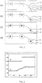
- FIG. 2 shows schematic courses of a processing laser beam 10 and a measuring beam 15 according to embodiments of the present disclosure.
- various scan figures of the measuring beam 15 for seam finding and seam quality monitoring with simultaneous high-frequency laser oscillation of the processing laser (2D wobbling process) are shown.
- the arrow indicates the advance direction of the welding process along a curved seam course 11.
- the processing laser beam 10 can carry out a high-frequency two-dimensional wobbling process along a line that is, for example, perpendicular to the course of the seam ( Figure 2 (a) ).
- Another possibility for the scan figure of the processing laser beam 10 is a circular figure or the shape of an 8 ( Figures 2 (b) and 2 (c) ).
- An alternative for the scan figure of the measuring beam 15 is a circle which, like the two lines in the forerun and in the trailing edge, contains the areas of seam detection before the laser and the seam quality after the laser ( Figure 2 (d) ).
- the scan figures of the measuring beam 15 and the scan figures of the processing beam 10 can be arbitrary can be combined with each other. Shapes other than a straight line or a figure in the form of a circle or an 8 can also be used.
- a circular figure is that the actuator system for deflecting the measuring beam 15 or the processing beam 10 has to carry out less abrupt deceleration and acceleration movements and thus a higher repetition frequency of the figure can be achieved.
- the figure of an 8 can be advantageous as a scan figure for the processing beam 10.
- the specific requirements for a given process, such as the seam geometry, the exact seam path or the feed speed, can decide whether a line scan or a circle scan is used.
- Another advantage of scanning the measuring beam 15 on a circle is that the course of the seam does not have to be known in advance of the actual processing.
- the two lines in the fore and aft should always be aligned perpendicular to the seam for a measurement.
- the information about the seam path can be passed on to the control software for the actuators of the measuring beam so that the lines can always be aligned perpendicular to the current seam direction during the process.
- there is no alignment of the scan figure since a certain segment of the circle always runs perpendicular to the seam for each seam direction, both in front of and behind the point of impact of the laser.
- Figure 3 shows measurement data that were recorded with an optical short coherence tomography (OCT) system for a fillet weld configuration for a line scan consisting of a line in the lead and a line in the trailing edge.
- OCT optical short coherence tomography
- the data shown are OCT measurement data from a line scan through processing optics for welding processes when welding an aluminum fillet weld joint.
- the distance values of the OCT measurement in micrometers are plotted on the Y-axis and the position on the component (any unit) is plotted on the X-axis.
- the height and the exact position of the fillet weld can be determined from the measurement data of the line in the area in front of the laser (see Fig. 3 (1)).
- the profile of the finished welded seam and its quality can be monitored from the measurement data of the line in the area after the laser (see Fig. 3 (2)).
- FIG. 10 shows a flow diagram of a method for laser machining in accordance with embodiments of the present disclosure. The method can be performed with reference to the Figures 1 to 3 described aspects.
- the method includes deflecting a machining laser beam in two spatial directions so that the machining laser beam executes a two-dimensional movement on at least one workpiece, deflecting a measuring beam in two spatial directions independently of the machining laser beam, and coupling the measuring beam into a beam path of the machining laser beam.
- the machining laser beam preferably performs an oscillating movement (“2D wobbling process”).
- the measuring beam can execute a linear or circular movement on the seam course, such as an edge course and / or a weld seam course, as it is for example in FIG Figure 2 is shown.
- the method further comprises determining a seam course using the measuring beam, for example in the advance of the machining laser beam, and following the seam course by the machining laser beam based on the determined seam course.
- two mutually independent deflection optics are used to deflect the machining laser beam and the measuring beam in two dimensions.
- the measuring beam is coupled into the beam path of the machining laser beam and is essentially superimposed coaxially with the machining laser beam in order to carry out, for example, an optical coherence tomography.
- a direction-independent seam finding can be achieved, for example in a 2D wobbling process.
- the seam can be found independently of a machining direction of the machining laser beam.
Landscapes
- Physics & Mathematics (AREA)
- Optics & Photonics (AREA)
- Engineering & Computer Science (AREA)
- Mechanical Engineering (AREA)
- Plasma & Fusion (AREA)
- Quality & Reliability (AREA)
- Health & Medical Sciences (AREA)
- General Health & Medical Sciences (AREA)
- Nuclear Medicine, Radiotherapy & Molecular Imaging (AREA)
- Radiology & Medical Imaging (AREA)
- General Physics & Mathematics (AREA)
- Laser Beam Processing (AREA)
- Length Measuring Devices By Optical Means (AREA)
Description
Die vorliegende Offenbarung betrifft ein Laserbearbeitungssystem, insbesondere ein System zur Materialbearbeitung mittels eines Laserstrahls, wie etwa ein Laserbearbeitungskopf zum Laserschweißen oder Laserschneiden, und ein Verfahren zur Laserbearbeitung. Die vorliegende Offenbarung betrifft insbesondere eine Nahtvermessung und Nahtverfolgung, z.B. mittels optischer Kohärenztomographie.The present disclosure relates to a laser processing system, in particular a system for material processing by means of a laser beam, such as a laser processing head for laser welding or laser cutting, and a method for laser processing. The present disclosure relates in particular to seam measurement and seam tracking, for example by means of optical coherence tomography.
Bei der Materialbearbeitung mittels eines Laserstrahls, wie beispielsweise Laserschweißen oder Laserschneiden, wird der von einer Laserlichtquelle, beispielsweise dem Ende einer Laserleitfaser, austretende Laserstrahl mit Hilfe einer Strahlführungs- und Fokussierungsoptik auf das zu bearbeitende Werkstück fokussiert. Standardmäßig wird ein Laserbearbeitungskopf mit einer Kollimatoroptik und einer Fokussierungsoptik verwendet, wobei das Laserlicht über eine Lichtleitfaser, auch als Laserquelle bezeichnet, zugeführt wird. Das Laserlicht tritt in einer Vorrichtung zur Materialbearbeitung mittels Laser, z.B. in einem Laserbearbeitungskopf, durch eine Vielzahl von optischen Elementen, wie z.B. Linsen, hindurch.When processing materials by means of a laser beam, such as laser welding or laser cutting, the laser beam emerging from a laser light source, for example the end of a laser guide fiber, is focused on the workpiece to be processed with the aid of beam guidance and focusing optics. A laser processing head with collimator optics and focusing optics is used as standard, the laser light being supplied via an optical fiber, also referred to as a laser source. The laser light passes through a large number of optical elements, such as lenses, in a device for processing materials by means of a laser, for example in a laser processing head.
Bei vielen Schweißprozessen ist es notwendig, dass der Auftreffpunkt des Bearbeitungslaserstrahls für einen stabilen Prozess sehr genau mit dem Nahtverlauf der beiden Fügepartner zusammenfällt. Um dies zu erreichen, kann während des Schweißprozesses durchgehend die Position der Naht ermittelt werden, so dass der Laser mit Hilfe einer Scannereinrichtung immer auf diese Nahtposition nachgeführt werden kann. Bekannte technische Lösungen zur Ermittlung der Nahtposition bei einem Schweißprozess beruhen jedoch zumeist auf der Projektion von Laserlinien auf das Bauteil senkrecht zum Nahtverlauf und Auswertung dieser Laserlinie mit Hilfe einer Kamera.In many welding processes it is necessary that the point of impact of the machining laser beam coincides very precisely with the seam path of the two joining partners for a stable process. In order to achieve this, the position of the seam can be determined continuously during the welding process, so that the laser can always be tracked to this seam position with the aid of a scanner device. However, known technical solutions for determining the seam position in a welding process are mostly based on the projection of laser lines onto the component perpendicular to the course of the seam and evaluation of this laser line with the aid of a camera.
Nachteil bei solchen Lichtschnittverfahren ist, dass die Ausrichtung der Laserlinie im Verhältnis zur Bearbeitungsoptik fest vorgegeben ist und dieses Verfahren somit nur für eine für einen bestimmten Prozess fest vorgegebene Schweißrichtung funktioniert. Anders gesagt ist die Ermittlung des Nahtverlaufs nicht richtungsunabhängig. Ein möglicher Ausweg beim Lichtschnittverfahren ist das Mitdrehen der gesamten Optik um dem Nahtverlauf zu folgen, was jedoch selbst bei Robotergeführten Prozessen nur begrenzt möglich ist.The disadvantage of such light section methods is that the alignment of the laser line in relation to the processing optics is fixed and this method therefore only works for a welding direction that is fixed for a specific process. In other words the determination of the seam course is not direction-independent. One possible way out with the light section process is to rotate the entire optics to follow the seam course, which is only possible to a limited extent, even with robot-guided processes.
In
Es ist eine Aufgabe der vorliegenden Offenbarung, ein Laserbearbeitungssystem, insbesondere ein System zur Materialbearbeitung mittels eines Laserstrahls, wie etwa ein Laserbearbeitungskopf oder ein System zum Laserschweißen, und ein Verfahren zur Laserbearbeitung bereitzustellen, die eine präzise Nahtverfolgung unabhängig von einer Bearbeitungsrichtung erlauben.It is an object of the present disclosure to provide a laser processing system, in particular a system for material processing by means of a laser beam, such as a laser processing head or a system for laser welding, and a method for laser processing that allow precise seam tracking regardless of a processing direction.
Diese Aufgabe wird durch den Gegenstand der unabhängigen Ansprüche gelöst. Vorteilhafte Ausgestaltungen der sind in den Unteransprüchen angegeben.This problem is solved by the subject matter of the independent claims. Advantageous embodiments of the are specified in the subclaims.
Gemäß Ausführungsformen der vorliegenden Offenbarung ist ein Laserbearbeitungssystem angegeben. Das Laserbearbeitungssystem umfasst eine erste Ablenk-Optik, die eingerichtet ist, um einen Bearbeitungslaserstrahl in zwei Raumrichtungen abzulenken, eine zweite Ablenk-Optik, die eingerichtet ist, um einen Messstrahl unabhängig vom Bearbeitungslaserstrahl in zwei Raumrichtungen abzulenken, und eine Einkopplungsvorrichtung, die in einem Strahlengang des Bearbeitungslaserstrahls angeordnet ist und eingerichtet ist, um den Messstrahl in den Strahlengang des Bearbeitungslaserstrahls einzukoppeln.In accordance with embodiments of the present disclosure, a laser processing system is provided. The laser processing system comprises a first deflection optics which are set up to deflect a processing laser beam in two spatial directions, a second Deflection optics that are set up to deflect a measuring beam independently of the machining laser beam in two spatial directions, and a coupling device that is arranged in a beam path of the machining laser beam and is set up to couple the measuring beam into the beam path of the machining laser beam.
Vorzugsweise umfasst die erste Ablenk-Optik zwei voneinander unabhängige erste Ablenkspiegel. Typischerweise ist die erste Ablenk-Optik für eine zweidimensionale Oszillation des Bearbeitungslaserstrahls eingerichtet, wie beispielsweise eine Bewegung entlang einer Linie, vorzugsweise entlang einer Linie senkrecht zum Nahtverlauf, eine kreisförmige Bewegung oder eine Bewegung in Form einer "8".The first deflecting optics preferably comprises two first deflecting mirrors that are independent of one another. The first deflection optics are typically set up for a two-dimensional oscillation of the processing laser beam, such as a movement along a line, preferably along a line perpendicular to the seam path, a circular movement or a movement in the form of an “8”.
Vorzugsweise umfasst die zweite Ablenk-Optik zwei voneinander unabhängige zweite Ablenkspiegel. Typischerweise ist die zweite Ablenk-Optik für eine lineare Bewegung und/oder eine kreisförmige Bewegung des Messstrahls eingerichtet.The second deflecting optics preferably comprises two second deflecting mirrors that are independent of one another. Typically, the second deflection optics is set up for a linear movement and / or a circular movement of the measuring beam.
Vorzugsweise ist die zweite Ablenk-Optik eingerichtet, um den Messstrahl unabhängig von einer Vorschubrichtung des Bearbeitungslaserstrahls auf mindestens ein Werkstück, und insbesondere auf einen Fügebereich zweier Werkstücke, zu lenken.The second deflection optics are preferably set up to direct the measuring beam onto at least one workpiece, and in particular onto a joining area of two workpieces, independently of a feed direction of the machining laser beam.
Vorzugsweise ist die Einkopplungsvorrichtung ein Strahlteiler. Typischerweise ist die Einkopplungsvorrichtung eingerichtet, um den Bearbeitungslaserstrahl und den Messstrahl im Wesentlichen koaxial zu überlagern.The coupling device is preferably a beam splitter. The coupling device is typically set up to superimpose the machining laser beam and the measuring beam essentially coaxially.
Vorzugsweise umfasst das Laserbearbeitungssystem eine Steuerung, die eingerichtet ist, um die erste Ablenk-Vorrichtung so zu steuern, dass der Bearbeitungslaserstrahl einem Nahtverlauf auf dem Werkstück folgt.The laser processing system preferably comprises a controller which is set up to control the first deflection device in such a way that the processing laser beam follows a seam path on the workpiece.
Vorzugsweise umfasst das Laserbearbeitungssystem eine Auswerteeinheit, die eingerichtet ist, um mit dem Messstrahl einen Nahtverlauf, wie etwa einen Kantenverlauf und/oder einen Schweißnahtverlauf, auf dem Werkstück zu vermessen. Die Auswerteeinheit kann einen Kantenverlauf von Fügestücken vor dem Bearbeitungslaserstrahl und/oder einen Schweißnahtverlauf nach dem Bearbeitungslaserstrahl vermessen. Hierbei kann die Auswerteeinheit insbesondere eingerichtet sein, den Nahtverlauf mittels optischer Kurzkohärenztomographie zu ermitteln.The laser processing system preferably comprises an evaluation unit which is set up to measure a seam course, such as an edge course and / or a weld seam course, on the workpiece with the measuring beam. The evaluation unit can measure an edge profile of joining pieces before the machining laser beam and / or a weld seam profile after the machining laser beam. In this case, the evaluation unit can in particular be set up to determine the course of the seam by means of optical short coherence tomography.
Gemäß einem weiteren Aspekt der vorliegenden Offenbarung ist ein Verfahren zur Laserbearbeitung angegeben. Das Verfahren umfasst ein Ablenken eines Bearbeitungslaserstrahls in zwei Raumrichtungen, so dass der Bearbeitungslaserstrahl eine zweidimensionale Bewegung auf mindestens einem Werkstück ausführt, ein Ablenken eines Messstrahls in zwei Raumrichtung unabhängig vom Bearbeitungslaserstrahl, und ein Einkoppeln des Messstrahls in einen Strahlengang des Bearbeitungslaserstrahls.According to a further aspect of the present disclosure, a method for laser machining is specified. The method comprises deflecting a machining laser beam in two spatial directions so that the machining laser beam executes a two-dimensional movement on at least one workpiece, deflecting a measuring beam in two spatial directions independently of the machining laser beam, and coupling the measuring beam into a beam path of the machining laser beam.
Vorzugsweise führt der Bearbeitungslaserstrahl eine oszillierende Bewegung aus (2D Wobbelprozess), wie beispielsweise eine lineare Bewegung, eine kreisförmige Bewegung oder eine Bewegung in Form einer "8".The machining laser beam preferably executes an oscillating movement (2D wobbling process), such as, for example, a linear movement, a circular movement or a movement in the form of an “8”.
Vorzugsweise führt der Messstrahl eine lineare oder kreisförmige Bewegung am Nahtverlauf, wie an einem Kantenverlauf und/oder einem Schweißnahtverlauf, aus.The measuring beam preferably executes a linear or circular movement on the course of the seam, such as on an edge course and / or a weld seam course.
Vorzugsweise umfasst das Verfahren weiter ein Bestimmen eines Nahtverlaufs, wie beispielwiese eines Kantenverlaufs zweier zu fügenden Werkstücke, unter Verwendung des Messstrahls, und ein Folgen des Nahtverlaufs durch den Bearbeitungslaserstrahl basierend auf dem bestimmten Nahtverlauf. Vorzugsweise wird zum Bestimmen des Nahtverlaufs optische Kurzkohärenztomographie verwendet.The method preferably further comprises determining a seam course, such as an edge course of two workpieces to be joined, using the measuring beam, and following the seam course with the processing laser beam based on the determined seam course. Optical short coherence tomography is preferably used to determine the course of the seam.
Bevorzugte, optionale Ausführungsformen und besondere Aspekte der Offenbarung ergeben sich aus den abhängigen Ansprüchen, den Zeichnungen und der vorliegenden Beschreibung.Preferred, optional embodiments and special aspects of the disclosure emerge from the dependent claims, the drawings and the present description.
Gemäß den hier beschriebenen Ausführungsformen wird bei einem Laserbearbeitungsprozess eine richtungsunabhängige Vermessung eines Nahtverlaufs auf einem Bauteil sowie eine genaue Positionierung des Laserstrahls auf die ermittelte Nahtposition ermöglicht. Ein optischer Messstrahl wird über eine eigene Aktorik geleitet und über eine Einkopplungsvorrichtung nach der Aktorik eines Bearbeitungslasers in dessen Strahlengang eingekoppelt und mit diesem überlagert. Durch diese Anordnung kann eine quasi koaxiale Vermessung der Bauteilgeometrie um die aktuelle Position des Bearbeitungslaserstrahls herum ermöglicht werden, unabhängig von der Bewegung des Bearbeitungslaserstrahls während des Bearbeitungsprozesses.According to the embodiments described here, a direction-independent measurement of a seam course on a component and an exact positioning of the laser beam at the determined seam position are made possible in a laser machining process. An optical measuring beam is guided via its own actuator system and coupled into its beam path via a coupling device after the actuator system of a processing laser and superimposed on it. This arrangement enables a quasi-coaxial measurement of the component geometry around the current position of the machining laser beam, regardless of the movement of the machining laser beam during the machining process.
Ein weiterer Vorteil der hier beschriebenen Ausführungsformen zur Nahtfindung gegenüber der Linienprojektion beim Lichtschnittverfahren ist die erreichbare Auflösung. Die hier beschriebenen Ausführungsformen, insbesondere bei Verwendung von optischer Kohärenztomographie, bieten eine Genauigkeit für den gemessenen Abstandswert von etwa 1 µm. Mit dieser Genauigkeit können senkrechte Strukturen auf dem Bauteil wie beispielsweise die Kantenhöhe einer Kehlnaht vermessen werden. Im Vergleich dazu ist die Auflösung, die bei einem Lichtschnittverfahren erreicht werden kann, hauptsächlich durch die Qualität der Linienprojektion begrenzt. Typische Linienbreiten liegen im Bereich von etwa 20 bis 100 µm. Dadurch ist die Auflösung der Strukturerkennung durch die Auswertung der Linien auf den Kamerabildern um etwa eine Größenordnung geringer.Another advantage of the embodiments described here for finding seams compared to line projection in the light section method is the resolution that can be achieved. The embodiments described here, in particular when using optical coherence tomography, offer an accuracy for the measured distance value of approximately 1 μm. Vertical structures on the component, such as the edge height of a fillet weld, can be measured with this accuracy. In comparison, the resolution that can be achieved with a light section method is mainly limited by the quality of the line projection. Typical line widths are in the range from about 20 to 100 µm. As a result, the resolution of the structure recognition through the evaluation of the lines on the camera images is about an order of magnitude lower.
Ausführungsbeispiele der Offenbarung sind in den Figuren dargestellt und werden im Folgenden näher beschrieben. Es zeigen:
-
Figur 1 -
Figur 2 -
Figur 3 -
Figur 4 ein Flussdiagramm eines Verfahrens zur Laserbearbeitung gemäß Ausführungsformen der vorliegenden Offenbarung.
-
Figure 1 a schematic view of a laser processing system according to embodiments of the present disclosure; -
Figure 2 schematic courses of a processing laser beam and a measuring beam according to embodiments of the present disclosure, -
Figure 3 Measurement data from a line scan of an optical coherence tomograph, and -
Figure 4 FIG. 3 is a flow diagram of a method for laser machining in accordance with embodiments of the present disclosure.
Im Folgenden werden, sofern nicht anders vermerkt, für gleiche und gleichwirkende Elemente gleiche Bezugszeichen verwendet.Unless otherwise noted, the same reference symbols are used below for elements that are the same and have the same effect.
Das Laserbearbeitungssystem 100 umfasst eine erste Ablenk-Optik 110, die eingerichtet ist, um einen Bearbeitungslaserstrahl 10 in zwei Raumrichtungen x, y abzulenken, eine zweite Ablenk-Optik 120, die eingerichtet ist, um einen Messstrahl 15 (Sensorstrahl) unabhängig vom Bearbeitungslaserstrahl 10 in zwei Raumrichtungen x, y abzulenken, und eine Einkopplungsvorrichtung 130, die in einem Strahlengang des Bearbeitungslaserstrahls 10 angeordnet ist und eingerichtet ist, um den Messstrahl 15 in den Strahlengang des Bearbeitungslaserstrahls 10 einzukoppeln. Vorzugsweise ist die zweite Ablenk-Optik 120 eingerichtet, um den Messstrahl 15 unabhängig von einer Vorschubrichtung oder Bearbeitungsrichtung 20 des Bearbeitungslaserstrahls 10 auf mindestens ein Werkstück 1, und insbesondere auf einen Fügebereich zweier Werkstücke zu lenken.The
Gemäß Ausführungsformen der vorliegenden Offenbarung erfolgt eine Nahtfindung beispielsweise beim Schweißen von Bauteilen zur genauen Positionierung des Bearbeitungslaserstrahls 10 relativ zu dieser Naht. Der durch die zweite Ablenk-Optik 120 in zwei Richtungen ablenkbare Messstrahl 15 ermöglicht dabei die Ermittlung der Nahtposition unabhängig von der aktuellen Vorschubrichtung eines gegebenen Bearbeitungsprozesses, wie beispielsweise eines Schweißprozesses. Durch eine eigene Aktorik im Strahlengang des Bearbeitungslaserstrahls kann eine Laserstrahloszillation in zwei Richtungen ("2D Wobbelprozess") erfolgen, die unabhängig von der Bewegung des Messstrahls 15 im Messstrahlengang durchgeführt werden kann.According to embodiments of the present disclosure, a seam is found, for example, when welding components for precise positioning of the
Gemäß Ausführungsformen umfasst das Laserbearbeitungssystem 100 (auch als "Laserbearbeitungskopf" bezeichnet) eine Laserquelle (nicht gezeigt) zur Bereitstellung des Bearbeitungslaserstrahls, wie beispielsweise eine Lichtleitfaser, sowie eine Kollimator-Optik 140, die eingerichtet ist, um den Bearbeitungslaserstrahl 10 zu kollimieren, und eine Fokussier-Optik 150, die eingerichtet ist, um den Bearbeitungslaserstrahl 10 auf wenigstens ein Werkstück 1 oder Bauteil zu fokussieren.According to embodiments, the laser processing system 100 (also referred to as “laser processing head”) comprises a laser source (not shown) for providing the processing laser beam, such as, for example, an optical fiber, as well as
Das Laserbearbeitungssystem 100 oder Teile davon, wie beispielsweise ein Schweißkopf, können gemäß Ausführungsformen entlang der Bearbeitungsrichtung 20 bewegbar sein. Die Bearbeitungsrichtung 20 kann eine Schweißrichtung und/oder eine Bewegungsrichtung des Laserbearbeitungssystems 100, wie beispielsweise des Schweißkopfes, bezüglich des Werkstücks 1 sein. Insbesondere kann die Bearbeitungsrichtung 20 eine horizontale Richtung sein. Die Bearbeitungsrichtung 20 kann auch als "Vorschubrichtung" oder "Prozessrichtung" bezeichnet werden.The
In einigen Ausführungsformen ist das Laserbearbeitungssystem 100 zum Schweißen eingerichtet. Das Laserbearbeitungssystem 100 kann eine Schweißnaht auf einem einzelnen Werkstück bilden, oder kann zwei Werkstücke ("Fügestücke") miteinander verschweißen, wie es im Beispiel der
Vorzugsweise umfasst das Laserbearbeitungssystem 100 eine Auswerteeinheit, die eingerichtet ist, um mit dem Messstrahl 15 den Nahtverlauf, wie den Kantenverlauf 2 und/oder den Schweißnahtverlauf 3, auf dem Werkstück zu vermessen. Die Auswerteeinheit kann einen Kantenverlauf von Fügestücken bezüglich der Bearbeitungsrichtung 20 vor dem Bearbeitungslaserstrahl 10 und/oder einen Schweißnahtverlauf nach dem Bearbeitungslaserstrahl 10 vermessen oder bestimmen. Die Auswerteeinheit kann beispielsweise in einem optischen Kohärenztomographen enthalten sein und den reflektierten Messstrahl auswerten, um den Nahtverlauf zu bestimmen.The
Typischerweise umfasst das Laserbearbeitungssystem 100 eine Steuerung, die eingerichtet ist, um die erste Ablenk-Vorrichtung 110 so zu steuern, dass der Bearbeitungslaserstrahl 10 dem Nahtverlauf auf dem Werkstück folgt. Die Steuerung kann mit der Auswerteeinheit verbunden sein und von der Auswerteeinheit Daten bezüglich des Nahtverlaufs erhalten. Die Steuerung kann die erste Ablenk-Vorrichtung 110 basierend auf diesen Daten so steuern, dass der Bearbeitungslaserstrahl 10 dem Nahtverlauf auf dem Werkstück folgt.The
Das Laserbearbeitungssystem 100 ist eingerichtet, um den Bearbeitungslaserstrahl 10 und den Messstrahl 15 in zwei Raumrichtungen x, y abzulenken. Anders gesagt sind für jeden der beiden Strahlen zwei Freiheitsgrade bereitgestellt. Die zwei Raumrichtungen x, y können Richtungen des Kartesischen Koordinatensystems sein, wie beispielsweise die X-Richtung und die Y-Richtung. Die zwei Raumrichtungen können orthogonal zueinander sein und eine Ebene aufspannen. Das Koordinatensystem kann bezüglich des Werkstücks definiert sein, und kann insbesondere bezüglich des Werkstücks fest bzw. stationär sein. Alternativ kann das Koordinatensystem bezüglich des sich in die Bearbeitungsrichtung 20 bewegenden Teils des Laserbearbeitungssystems 100, wie beispielsweise des Schweißkopfes definiert sein, und kann insbesondere bezüglich des Schweißkopfes fest bzw. stationär sein.The
Vorzugsweise umfasst die erste Ablenk-Optik 110 wenigstens einen ersten Ablenkspiegel, und insbesondere zwei voneinander unabhängige erste Ablenkspiegel. Die unabhängigen ersten Ablenkspiegel können um eine jeweilige Rotationsachse drehbar gelagert sein, um den Bearbeitungslaserstrahl 10 in die zwei Raumrichtungen abzulenken. Die Rotationsachsen können zueinander senkrecht sein und die zwei Freiheitsgrade bereitstellen, durch die der Bearbeitungslaserstrahl 10 zweidimensional abgelenkt werden kann.The
Die Laseroptik verfügt damit über eine Aktorik, wie beispielsweise eine Scanner-Optik, bestehend aus zwei unabhängigen Scanspiegeln, durch die der Bearbeitungslaserstrahl 10 in zwei Richtungen auf dem Bauteil ausgelenkt werden kann. Dadurch ist eine genaue Positionierung des Bearbeitungslaserstrahls 10 auf dem Bauteil in zwei Raumrichtungen möglich, um dem Nahtverlauf bei einem Schweißprozess, beispielsweise einer Kehlnaht, zu folgen.The laser optics thus have an actuator, such as, for example, scanner optics, consisting of two independent scanning mirrors, by means of which the
Gemäß Ausführungsformen ist die erste Ablenk-Optik 110 für eine zweidimensionale Oszillation des Bearbeitungslaserstrahls 100 eingerichtet. Insbesondere kann der Bearbeitungslaserstrahl 10 während des Prozesses in zwei Richtungen oszillieren, um gezielt den Einflussbereich des Bearbeitungslaserstrahls 10 auf dem Bauteil zu vergrößern und dadurch eine stabilere Nahtanbindung zu erreichen. Bei einem solchen 2D Wobbelprozess kann der Bearbeitungslaserstrahl 10 auf einer bestimmten zweidimensionalen Scanfigur auf dem Bauteil ausgelenkt werden, die beispielsweise aus einer Linie, einem Kreis (
Durch eine hochfrequente Bewegung des Bearbeitungslaserstrahls 10 auf einer zweidimensionalen Figur können Prozessgrößen wie Lasergeschwindigkeit, Einschweißtiefe und Nahtbreite über die Amplitude sowie die Frequenz der Bewegung gezielt eingestellt werden. So kann beispielsweise für eine gegebene Nahtgeometrie durch Anpassen der Amplitude der Laseroszillation der Einflussbereich des Lasers vergrößert und dadurch eine bessere Spaltüberbrückbarkeit erreicht werden. Des Weiteren kann für eine Mischverbindung zweier verschiedener Materialien, wie Kupfer und Aluminium, durch eine Wahl von Amplitude und Frequenz das Durchmischungsverhältnis in der Schmelze gezielt eingestellt werden.By means of a high-frequency movement of the
In einigen Ausführungsformen umfasst die zweite Ablenk-Optik 120 wenigstens einen zweiten Ablenkspiegel, und insbesondere zwei voneinander unabhängige zweite Ablenkspiegel. Die unabhängigen zweiten Ablenkspiegel können um eine jeweilige Rotationsachse drehbar gelagert sein, um den Messstrahl 15 in die zwei Raumrichtungen abzulenken. Die Rotationsachsen können zueinander senkrecht sein und die zwei Freiheitsgrade bereitstellen, durch die der Messstrahl 15 zweidimensional abgelenkt werden kann. Typischerweise ist die zweite Ablenk-Optik 120 für eine lineare Bewegung und/oder eine kreisförmige Bewegung des Messstrahls eingerichtet, wie es unter Bezugnahme auf die
Gemäß Ausführungsformen der vorliegenden Offenbarung ist die Einkopplungsvorrichtung 130 ein Strahlteiler. Typischerweise ist die Einkopplungsvorrichtung 130 eingerichtet, um den Bearbeitungslaserstrahl 10 und den Messstrahl 15 im Wesentlichen koaxial zu überlagern. Die Einkopplungsvorrichtung 130 kann der Fokussier-Optik 150 vorgelagert sein, so dass der Bearbeitungslaserstrahl 10 und der Messstrahl 15 beide durch die Fokussier-Optik 150 hindurchlaufen.According to embodiments of the present disclosure, the
Gemäß den hier beschriebenen Ausführungsformen wird das Messlicht des Sensorsystems in den Strahlengang des Bearbeitungslasers eingekoppelt, wobei die Position des Messstrahls 15 auf dem Bauteil über eine eigene Aktorik oder Scannereinheit verfahren werden kann. Das Sensorprinzip zur Abstandsmessung kann beispielsweise auf der optischen Kurzkohärenz-Interferometrie (OCT) beruhen. Die Einkopplung des Messstrahls 15 kann über einen Strahlteiler geschehen, der sich im Strahlengang des heißen Laserstrahls nach der Aktorik des Bearbeitungslasers befindet. Durch diese Anordnung wird eine quasi koaxiale Überlagerung des Messstrahls 15 und des Bearbeitungslaserstrahls 10 erreicht, wobei jeder der beiden Strahlen unabhängig voneinander durch eine eigene Aktorik in zwei Richtungen abgelenkt werden kann. Ein wesentlicher Vorteil besteht darin, dass mit dem Messstrahl 15 die Bauteilgeometrie um die aktuelle Position des Bearbeitungslaserstrahls 10 herum vermessen werden kann, unabhängig von der Bewegung des Bearbeitungslaserstrahls 10 während des Prozesses.According to the embodiments described here, the measuring light of the sensor system is coupled into the beam path of the processing laser, with the position of the
So kann der Messstrahl 15 beispielsweise wiederholt zunächst entlang einer Linie bewegt werden, die sich in Schweißrichtung vor der Laserposition befindet, um die genaue Position der Schweißnaht zu detektieren und einzustellen. Anschließend kann der Messstrahl 15 beispielsweise wiederholt entlang einer Linie bewegt werden, die sich in Schweißrichtung nach der Laserposition befindet, um die Nahtgeometrie zu vermessen (siehe
Neben der genauen Positionierung des Laserstrahls auf den Nahtverlauf einer Verbindung kann es außerdem für die Qualität des Schweißprozesses sowie die Stabilität der Verbindung von Vorteil sein, wenn der Laserstrahl um die zuvor ermittelte Nahtposition herum eine oszillierende Bewegung, einen sogenannten Wobbelprozess, ausführt. Beispielsweise kann nur der Mittelpunkt dieser oszillierenden Bewegung mit der Nahtposition zusammenfallen, während der Laser hochfrequent um diesen Mittelpunkt herumbewegt wird. Die Bewegung kann dabei je nach Nahtgeometrie und dem Material der Bauteile auf einer linearen Bahn senkrecht zur Naht oder auch auf einer vorgegebenen zweidimensionalen Figur, wie beispielsweise einem Kreis oder einer 8, erfolgen. Mit den hier beschriebenen Ausführungsformen kann somit eine hochfrequente Laserstrahloszillation entlang einer zweidimensionalen Scanfigur erfolgen, deren Position sehr genau dem Verlauf einer Schweißnaht folgt, unabhängig von der Richtung dieser Naht auf dem Bauteil.In addition to the precise positioning of the laser beam on the seam path of a connection, it can also be of advantage for the quality of the welding process and the stability of the connection if the laser beam executes an oscillating movement, a so-called wobbling process, around the previously determined seam position. For example, only the center of this oscillating movement can coincide with the seam position, while the laser is moved around this center at high frequencies. The movement can take place, depending on the seam geometry and the material of the components, on a linear path perpendicular to the seam or on a predetermined two-dimensional figure, such as a circle or an 8. With the embodiments described here, a high-frequency laser beam oscillation can thus take place along a two-dimensional scan figure, the position of which follows the course of a weld seam very precisely, regardless of the direction of this seam on the component.
Durch das schnelle Abscannen der Oberfläche mit dem Messstrahl 15 kann ein Höhenprofil entlang der Scanfiguren erstellt werden. Durch die Linie vor dem Laserstrahl erhält man die Position der Naht und durch das Scannen einer Linie nach dem Laserstrahl das Höhenprofil der fertigen Schweißraupe. Gleichzeitig kann der Bearbeitungslaserstrahl 10 einen hochfrequenten zweidimensionalen Wobbelprozess entlang einer Linie, die z.B. senkrecht auf dem Nahtverlauf steht, ausführen (
Ein Vorteil einer Kreisfigur besteht darin, dass die Aktorik zur Ablenkung des Messstrahls 15 bzw. des Bearbeitungsstrahls 10 weniger abrupte Abbrems- und Beschleunigungsbewegungen durchführen muss und somit eine höhere Wiederholfrequenz der Figur erreicht werden kann. Aus demselben Grund kann die Figur einer 8 als Scanfigur für den Bearbeitungsstrahl 10 vorteilhaft sein. Die spezifischen Anforderungen an einen gegebenen Prozess, wie z.B. die Nahtgeometrie, der genaue Nahtverlauf oder auch die Vorschubgeschwindigkeit, können darüber entscheiden, ob ein Linienscan oder ein Kreisscan eingesetzt wird.One advantage of a circular figure is that the actuator system for deflecting the
Ein weiterer Vorteil beim Scannen des Messstrahls 15 auf einem Kreis besteht darin, dass der Verlauf der Naht im Vorfeld zur eigentlichen Bearbeitung nicht bekannt sein muss. Die beiden Linien im Vor- und Nachlauf sollten für eine Messung immer senkrecht zur Naht ausgerichtet sein. Dafür kann die Information des Nahtverlaufs an die Ansteuerungssoftware für die Aktorik des Messstrahls weitergegeben werden, damit die Linien während des Prozesses immer senkrecht zur aktuellen Nahtrichtung ausgerichtet werden können. Bei einem Kreisscan entfällt eine Ausrichtung der Scanfigur, da für jede Nahtrichtung immer ein bestimmtes Segment des Kreises senkrecht zur Naht verläuft, sowohl vor als auch hinter dem Auftreffpunkt des Lasers.Another advantage of scanning the
Das Verfahren umfasst ein Ablenken eines Bearbeitungslaserstrahls in zwei Raumrichtung, so dass der Bearbeitungslaserstrahl eine zweidimensionale Bewegung auf mindestens einem Werkstück ausführt, ein Ablenken eines Messstrahls in zwei Raumrichtung unabhängig vom Bearbeitungslaserstrahl, und ein Einkoppeln des Messstrahls in einen Strahlengang des Bearbeitungslaserstrahls. Vorzugsweise führt der Bearbeitungslaserstrahl eine oszillierende Bewegung aus ("2D Wobbelprozess"). Der Messstrahl kann eine lineare oder kreisförmige Bewegung am Nahtverlauf, wie einen Kantenverlauf und/oder einen Schweißnahtverlauf, ausführen, wie es beispielsweise in
Gemäß den hier beschriebenen Ausführungsformen werden zwei voneinander unabhängige Ablenk-Optiken verwendet, um den Bearbeitungslaserstrahl und den Messstrahl jeweils zweidimensional auszulenken. Der Messstrahl wird in den Strahlengang des Bearbeitungslaserstrahls eingekoppelt und mit dem Bearbeitungslaserstrahl im Wesentlichen koaxial überlagert, um beispielswiese eine optische Kohärenztomographie durchzuführen. Damit kann eine richtungsunabhängige Nahtfindung beispielsweise in einem 2D Wobbelprozess erreicht werden. Insbesondere kann die Nahtfindung unabhängig von einer Bearbeitungsrichtung des Bearbeitungslaserstrahls erfolgen.According to the embodiments described here, two mutually independent deflection optics are used to deflect the machining laser beam and the measuring beam in two dimensions. The measuring beam is coupled into the beam path of the machining laser beam and is essentially superimposed coaxially with the machining laser beam in order to carry out, for example, an optical coherence tomography. In this way, a direction-independent seam finding can be achieved, for example in a 2D wobbling process. In particular, the seam can be found independently of a machining direction of the machining laser beam.
Claims (15)
- A laser machining system (100), comprising:first deflection optics (110), which are designed for deflecting a machining laser beam (10) in two directions in space (x, y);second deflection optics (120), which are designed for deflecting a measuring beam (15) in two directions in space (x, y) independently of the machining laser beam (10); anda coupling device (130), which is designed for coupling the measuring beam (15) into the beam path of the machining laser beam (10),characterised in that the coupling device (130) is arranged in the beam path of the machining laser beam (10) after the first deflection optics (110).
- The laser machining system (100) according to claim 1, wherein the first deflection optics (110) comprise two independent first deflection mirrors.
- The laser machining system (100) according to claim 1 or 2, wherein the first deflection optics (110) are designed for a two-dimensional oscillation of the machining laser beam (10).
- The laser machining system (100) according to one of claims 1-3, wherein the second deflection optics (120) comprise two independent second deflection mirrors.
- The laser machining system (100) according to one of claims 1-4, wherein the second deflection optics (120) are designed for a linear or circular motion of the measuring beam (15).
- The laser machining system (100) according to one of claims 1-5, wherein the second deflection optics (120) are designed for deflecting the measuring beam (15) on at least one workpiece (1) independently of an advance direction (20) of the machining laser beam (10).
- The laser machining system (100) according to one of claims 1-6, wherein the coupling device (130) is a beam splitter.
- The laser machining system (100) according to one of claims 1-7, wherein the coupling device (130) is designed for superimposing the machining laser beam (10) and the measuring beam (15) coaxially.
- The laser machining system (100) according to one of claims 1-8, further comprising an evaluation unit that is designed for determining a seam progression on a workpiece (1) with the measuring beam (150).
- The laser machining system (100) according to one of claims 1-9, further comprising a control unit that is designed for controlling the first deflection optics (110) in such a way that the machining laser beam (10) tracks a seam progression on a workpiece (1).
- The laser machining system (100) according to claim 10, wherein the evaluation unit comprises an optical coherence interferometer.
- A laser machining method, comprising:deflecting a machining laser beam (10) in two directions in space (x, y) with first deflection optics (110) such that the machining laser beam (10) carries out a two-dimensional motion on at least one workpiece (1);deflecting a measuring beam (15) in two directions in space (x, y) independently of the machining laser beam (10) with second deflection optics (120); andcoupling the measuring beam (15) into a beam path of the machining laser beam (10),characterised in that the measuring beam is coupled through a coupling device (130) arranged after the first deflection optics (110) in the beam path of the machining laser beam (10).
- The method according to claim 12, wherein the machining laser beam (10) carries out an oscillating motion.
- The method according to claim 12 or 13, wherein the measuring beam (15) carries out a linear or circular motion.
- The method according to one of claims 12-14, further comprising:determining a seam progression by using the measuring beam (15) by means of optical coherence tomography; andtracking the seam progression by means of the machining laser beam (10) based on the determined seam progression.
Applications Claiming Priority (2)
| Application Number | Priority Date | Filing Date | Title |
|---|---|---|---|
| DE102017126867.7A DE102017126867A1 (en) | 2017-11-15 | 2017-11-15 | Laser processing system and method for laser processing |
| PCT/EP2018/078430 WO2019096529A1 (en) | 2017-11-15 | 2018-10-17 | Laser machining system and method for laser machining |
Publications (2)
| Publication Number | Publication Date |
|---|---|
| EP3710196A1 EP3710196A1 (en) | 2020-09-23 |
| EP3710196B1 true EP3710196B1 (en) | 2022-01-05 |
Family
ID=63915262
Family Applications (1)
| Application Number | Title | Priority Date | Filing Date |
|---|---|---|---|
| EP18789601.4A Active EP3710196B1 (en) | 2017-11-15 | 2018-10-17 | Laser machining system and method for laser machining |
Country Status (7)
| Country | Link |
|---|---|
| US (1) | US11148232B2 (en) |
| EP (1) | EP3710196B1 (en) |
| JP (1) | JP6999032B2 (en) |
| KR (1) | KR20200081493A (en) |
| CN (1) | CN111344101A (en) |
| DE (1) | DE102017126867A1 (en) |
| WO (1) | WO2019096529A1 (en) |
Cited By (1)
| Publication number | Priority date | Publication date | Assignee | Title |
|---|---|---|---|---|
| US12097572B2 (en) | 2018-07-19 | 2024-09-24 | Ipg Photonics Corporation | Systems and methods for monitoring and/or controlling wobble-processing using inline coherent imaging (ICI) |
Families Citing this family (28)
| Publication number | Priority date | Publication date | Assignee | Title |
|---|---|---|---|---|
| DE102017211982B4 (en) * | 2017-07-13 | 2019-04-18 | Trumpf Laser- Und Systemtechnik Gmbh | Method and device for joining at least two workpieces |
| WO2020132282A1 (en) * | 2018-12-19 | 2020-06-25 | Ipg Photonics Corporation | Monitoring material processing using imaging signal density determined from inline coherent imaging (ici) |
| CN111347157B (en) * | 2018-12-21 | 2023-04-28 | 松下知识产权经营株式会社 | Laser welding device and laser welding method |
| DE102019116280B3 (en) * | 2019-06-14 | 2020-12-17 | Etalon Ag | Method and apparatus for determining a length |
| JP7462387B2 (en) * | 2019-06-26 | 2024-04-05 | ダイハツ工業株式会社 | Sealer application device |
| JP7317429B2 (en) * | 2019-12-19 | 2023-07-31 | エルジー エナジー ソリューション リミテッド | Battery module and manufacturing method thereof |
| CN111266684B (en) * | 2020-03-11 | 2022-07-29 | 华工法利莱切焊系统工程有限公司 | Laser filler wire welding bare wire centering monitoring method, bare wire centering monitoring device and laser filler wire welding device |
| JP7222945B2 (en) * | 2020-03-12 | 2023-02-15 | 株式会社アイシン | Stator manufacturing method for rotary electric machine |
| DE102020203983A1 (en) * | 2020-03-27 | 2021-09-30 | Trumpf Laser Gmbh | Method for OCT weld seam monitoring as well as the associated laser processing machine and computer program product |
| US12403548B2 (en) * | 2020-08-19 | 2025-09-02 | Panasonic Intellectual Property Management Co., Ltd. | Laser processing apparatus and laser processing method |
| US12179284B2 (en) * | 2020-08-27 | 2024-12-31 | Dm3D Technology, Llc | Vision-based rotary part offset correction for weld toolpathing |
| CN112157368B (en) * | 2020-09-24 | 2021-11-23 | 长春理工大学 | Laser non-penetration welding seam penetration nondestructive testing method |
| KR102299184B1 (en) * | 2020-09-28 | 2021-09-07 | 모니텍주식회사 | Laser welding monitoring system using Optical Coherence Tomography |
| CN112902876B (en) * | 2021-01-14 | 2022-08-26 | 西北工业大学 | Method for measuring weld deflection of spin forming curved surface member of tailor-welded blank |
| JP7568522B2 (en) * | 2021-01-19 | 2024-10-16 | ファナック株式会社 | Laser Processing Equipment |
| DE102021201989A1 (en) | 2021-03-02 | 2022-09-08 | Trumpf Laser- Und Systemtechnik Gmbh | Method for monitoring a laser welding process and associated laser processing machine |
| CN114434001A (en) * | 2021-03-24 | 2022-05-06 | 西华大学 | An Algorithm for Autonomous Tracking of Weld Trajectory |
| DE102021113597A1 (en) | 2021-05-26 | 2022-12-01 | Trumpf Laser Gmbh | Process and laser processing device for the production of a bipolar plate |
| DE102021115036A1 (en) * | 2021-06-10 | 2022-12-15 | Precitec Gmbh & Co. Kg | Process for laser processing of a workpiece and associated laser processing system |
| DE102022100231A1 (en) * | 2022-01-05 | 2023-07-06 | Trumpf Laser- Und Systemtechnik Gmbh | Process for laser beam welding of several components at different processing points of a component and laser welding device |
| KR20230117891A (en) | 2022-02-03 | 2023-08-10 | 주식회사 탑아이앤티 | Potable card payment device holder |
| DE102022106558A1 (en) | 2022-03-21 | 2023-09-21 | Blackbird Robotersysteme Gmbh | Method for detecting a surface of at least one object for a processing device |
| US20250033144A1 (en) * | 2022-07-08 | 2025-01-30 | Lg Energy Solution, Ltd. | Welding device |
| WO2024009286A2 (en) * | 2022-07-08 | 2024-01-11 | 주식회사 엘지에너지솔루션 | Apparatus for manufacturing secondary battery and method for manufacturing secondary battery using same |
| DE102022129220B3 (en) | 2022-11-04 | 2024-03-28 | Lessmüller Lasertechnik GmbH | Measuring device and method for carrying out measurements on a workpiece as well as processing system and method for welding |
| DE102022129218A1 (en) | 2022-11-04 | 2024-05-08 | Lessmüller Lasertechnik GmbH | Device and method for carrying out measurements on a workpiece and machining system and method for machining a workpiece |
| CN116786948B (en) * | 2023-06-27 | 2025-08-05 | 上海交通大学 | Method and system for adjusting welding process parameters of lap joints |
| DE102024106057A1 (en) * | 2024-03-01 | 2025-09-04 | TRUMPF Laser SE | Method for correcting the image field plane of a scanner optics of a laser system |
Family Cites Families (23)
| Publication number | Priority date | Publication date | Assignee | Title |
|---|---|---|---|---|
| JP2662041B2 (en) * | 1989-07-28 | 1997-10-08 | 株式会社日立製作所 | Drilling method using laser beam and method for manufacturing nozzle of fuel injection valve using the same |
| US5045668A (en) | 1990-04-12 | 1991-09-03 | Armco Inc. | Apparatus and method for automatically aligning a welding device for butt welding workpieces |
| DE59709824D1 (en) | 1996-07-29 | 2003-05-22 | Elpatronic Ag Bergdietikon | Method and device for edge tracking and edge testing |
| FR2809646B1 (en) | 2000-05-31 | 2002-09-27 | Air Liquide | METHOD AND DEVICE FOR HYBRID LASER-ARC WELDING WITH CONTROLLING THE POSITIONING OF MASS TAKES |
| JP3424001B2 (en) * | 2000-12-28 | 2003-07-07 | 川崎重工業株式会社 | Laser welding method and laser welding apparatus |
| TWI382795B (en) * | 2005-03-04 | 2013-01-11 | 日立比亞機械股份有限公司 | A method of opening a printed circuit board and an opening device for a printed circuit board |
| US7983470B2 (en) * | 2005-11-14 | 2011-07-19 | Precitec Vision Gmbh & Co. Kg | Method and device for assessing joins of workpieces |
| DE102007016444B4 (en) * | 2007-04-05 | 2024-08-22 | Precitec Optronik Gmbh | Processing facility |
| DE102009007769B4 (en) | 2009-02-05 | 2016-07-14 | Jenoptik Automatisierungstechnik Gmbh | Laser processing head with integrated sensor device for focus position monitoring |
| DE102009057209B4 (en) | 2009-02-09 | 2012-06-28 | Scansonic Mi Gmbh | Device with scanner optics for material processing by laser |
| DE102009042986B3 (en) | 2009-09-25 | 2011-03-03 | Precitec Kg | Welding head and method for joining a workpiece |
| DE102010011253B4 (en) | 2010-03-12 | 2013-07-11 | Precitec Kg | Laser processing head, robot apparatus and method for processing a workpiece by means of a laser beam |
| CA2905616C (en) | 2013-03-13 | 2021-08-24 | Queen's University At Kingston | Methods and systems for characterizing laser machining properties by measuring keyhole dynamics using interferometry |
| DE102013008269C5 (en) * | 2013-05-15 | 2019-01-24 | Precitec Optronik Gmbh | Processing head for a laser processing device |
| DE102014113283B4 (en) | 2014-09-15 | 2016-11-03 | Blackbird Robotersysteme Gmbh | Device for remote laser processing with sensor scanner device |
| JP2016000421A (en) * | 2014-06-12 | 2016-01-07 | 株式会社レーザックス | Laser processing system and laser processing method |
| JP6376963B2 (en) | 2014-12-09 | 2018-08-22 | 日立造船株式会社 | Laser welding apparatus having groove monitoring device and groove monitoring method for laser welding device |
| DE102015007142A1 (en) | 2015-06-02 | 2016-12-08 | Lessmüller Lasertechnik GmbH | Measuring device for a laser processing system and method for carrying out position measurements by means of a measuring beam on a workpiece |
| DE102015015112B4 (en) | 2015-11-23 | 2022-02-10 | Lessmüller Lasertechnik GmbH | Device and method for monitoring a machining process for material machining using an optical measuring beam |
| DE102015015330B4 (en) * | 2015-11-25 | 2024-03-21 | Lessmüller Lasertechnik GmbH | Processing device and method for monitoring a processing process carried out with a processing device |
| DE102016001661B3 (en) * | 2016-02-12 | 2017-04-13 | Lessmüller Lasertechnik GmbH | Measuring device and method for determining a relative inclination of a workpiece by means of optical coherence tomography during processing |
| DE102016106648B4 (en) * | 2016-04-12 | 2018-08-09 | Blackbird Robotersysteme Gmbh | Calibration method for a sensor deflection system of a laser processing apparatus and calibration system for carrying out such a calibration method |
| CN110023026B (en) * | 2016-10-20 | 2021-03-30 | 通用汽车环球科技运作有限责任公司 | Laser welding of overlapping metal workpieces assisted by the focal position of an oscillating laser beam |
-
2017
- 2017-11-15 DE DE102017126867.7A patent/DE102017126867A1/en active Pending
-
2018
- 2018-10-17 KR KR1020207017166A patent/KR20200081493A/en not_active Ceased
- 2018-10-17 CN CN201880073395.4A patent/CN111344101A/en active Pending
- 2018-10-17 WO PCT/EP2018/078430 patent/WO2019096529A1/en not_active Ceased
- 2018-10-17 JP JP2020527022A patent/JP6999032B2/en active Active
- 2018-10-17 EP EP18789601.4A patent/EP3710196B1/en active Active
- 2018-11-08 US US16/184,598 patent/US11148232B2/en active Active
Cited By (2)
| Publication number | Priority date | Publication date | Assignee | Title |
|---|---|---|---|---|
| US12097572B2 (en) | 2018-07-19 | 2024-09-24 | Ipg Photonics Corporation | Systems and methods for monitoring and/or controlling wobble-processing using inline coherent imaging (ICI) |
| EP3807041B1 (en) * | 2018-07-19 | 2025-08-27 | IPG Photonics Corporation | System and method for monitoring and/or controlling wobble-processing using inline coherent imaging (ici) |
Also Published As
| Publication number | Publication date |
|---|---|
| JP2021502901A (en) | 2021-02-04 |
| KR20200081493A (en) | 2020-07-07 |
| WO2019096529A1 (en) | 2019-05-23 |
| CN111344101A (en) | 2020-06-26 |
| DE102017126867A1 (en) | 2019-05-16 |
| US11148232B2 (en) | 2021-10-19 |
| JP6999032B2 (en) | 2022-01-18 |
| EP3710196A1 (en) | 2020-09-23 |
| US20190143458A1 (en) | 2019-05-16 |
Similar Documents
| Publication | Publication Date | Title |
|---|---|---|
| WO2019096529A1 (en) | Laser machining system and method for laser machining | |
| DE102018002960B4 (en) | LASER PROCESSING SYSTEM WITH MEASURING FUNCTION | |
| DE102016014564B4 (en) | Measuring device for monitoring a machining process using measurement information acquired at different measuring positions | |
| EP0770445B1 (en) | Control and positioning method of a beam or jet for machining a workpiece | |
| DE102015015330B4 (en) | Processing device and method for monitoring a processing process carried out with a processing device | |
| EP2544849B1 (en) | Laser machning head und method of machining a workpiece using a laser beam | |
| DE102007027377B4 (en) | Device and method for processing a workpiece by means of a laser beam | |
| EP1979124B1 (en) | Laser beam welding head, its use and beam welding method | |
| DE102018219129B3 (en) | Method and computer program product for OCT measurement beam adjustment | |
| WO2018178387A1 (en) | Device and method for an additive manufacture | |
| WO2014183849A1 (en) | Machining head for a laser machining device comprising a path-length modulator in the reference arm; method for laser machining of a workpiece, comprising corresponding steps | |
| DE102016001661B3 (en) | Measuring device and method for determining a relative inclination of a workpiece by means of optical coherence tomography during processing | |
| WO2018059901A1 (en) | Method and laser machining tool for laser welding a first and a second workpiece portion | |
| DE102017010055A1 (en) | Laser beam welding of geometric figures with OCT seam guide | |
| DE102014203025A1 (en) | Method for laser beam welding and welding head | |
| WO2010088873A1 (en) | Apparatus having scanner lens for material processing by way of laser | |
| EP1238746A2 (en) | Method and device for robotically controlled laser cutting and welding | |
| DE102012212278A1 (en) | Arrangement for producing holes or welds | |
| DE4026759A1 (en) | LASER WELDING SYSTEM WORKING WITH WELDING SHOCK TRACKING | |
| EP2091699B1 (en) | Method and device for fine-positioning a tool having a handling device | |
| DE102020203983A1 (en) | Method for OCT weld seam monitoring as well as the associated laser processing machine and computer program product | |
| DE102016010508A1 (en) | Apparatus, processing apparatus and method for performing a machining process by means of a high-energy machining beam while adjusting the machining beam in accordance with a current processing situation | |
| DE102004050819B4 (en) | Method and device for laser beam machining | |
| EP0037521B1 (en) | Process and apparatus for automatically tracking a weld seam | |
| DE202006005916U1 (en) | Monitoring device for jet mechanisms e.g. remote lasers, has jet e.g. laser beam for treatment of workpiece and movable jet head e.g. laser head, where monitoring device has sensor unit attached to jet head, preferably at exit of jet optics |
Legal Events
| Date | Code | Title | Description |
|---|---|---|---|
| STAA | Information on the status of an ep patent application or granted ep patent |
Free format text: STATUS: UNKNOWN |
|
| STAA | Information on the status of an ep patent application or granted ep patent |
Free format text: STATUS: THE INTERNATIONAL PUBLICATION HAS BEEN MADE |
|
| PUAI | Public reference made under article 153(3) epc to a published international application that has entered the european phase |
Free format text: ORIGINAL CODE: 0009012 |
|
| STAA | Information on the status of an ep patent application or granted ep patent |
Free format text: STATUS: REQUEST FOR EXAMINATION WAS MADE |
|
| 17P | Request for examination filed |
Effective date: 20200403 |
|
| AK | Designated contracting states |
Kind code of ref document: A1 Designated state(s): AL AT BE BG CH CY CZ DE DK EE ES FI FR GB GR HR HU IE IS IT LI LT LU LV MC MK MT NL NO PL PT RO RS SE SI SK SM TR |
|
| AX | Request for extension of the european patent |
Extension state: BA ME |
|
| DAV | Request for validation of the european patent (deleted) | ||
| DAX | Request for extension of the european patent (deleted) | ||
| GRAP | Despatch of communication of intention to grant a patent |
Free format text: ORIGINAL CODE: EPIDOSNIGR1 |
|
| STAA | Information on the status of an ep patent application or granted ep patent |
Free format text: STATUS: GRANT OF PATENT IS INTENDED |
|
| INTG | Intention to grant announced |
Effective date: 20210831 |
|
| GRAS | Grant fee paid |
Free format text: ORIGINAL CODE: EPIDOSNIGR3 |
|
| GRAA | (expected) grant |
Free format text: ORIGINAL CODE: 0009210 |
|
| STAA | Information on the status of an ep patent application or granted ep patent |
Free format text: STATUS: THE PATENT HAS BEEN GRANTED |
|
| AK | Designated contracting states |
Kind code of ref document: B1 Designated state(s): AL AT BE BG CH CY CZ DE DK EE ES FI FR GB GR HR HU IE IS IT LI LT LU LV MC MK MT NL NO PL PT RO RS SE SI SK SM TR |
|
| REG | Reference to a national code |
Ref country code: GB Ref legal event code: FG4D Free format text: NOT ENGLISH |
|
| REG | Reference to a national code |
Ref country code: CH Ref legal event code: EP |
|
| REG | Reference to a national code |
Ref country code: AT Ref legal event code: REF Ref document number: 1460089 Country of ref document: AT Kind code of ref document: T Effective date: 20220115 |
|
| REG | Reference to a national code |
Ref country code: DE Ref legal event code: R096 Ref document number: 502018008433 Country of ref document: DE |
|
| REG | Reference to a national code |
Ref country code: IE Ref legal event code: FG4D Free format text: LANGUAGE OF EP DOCUMENT: GERMAN |
|
| REG | Reference to a national code |
Ref country code: LT Ref legal event code: MG9D |
|
| REG | Reference to a national code |
Ref country code: NL Ref legal event code: MP Effective date: 20220105 |
|
| PG25 | Lapsed in a contracting state [announced via postgrant information from national office to epo] |
Ref country code: NL Free format text: LAPSE BECAUSE OF FAILURE TO SUBMIT A TRANSLATION OF THE DESCRIPTION OR TO PAY THE FEE WITHIN THE PRESCRIBED TIME-LIMIT Effective date: 20220105 |
|
| PG25 | Lapsed in a contracting state [announced via postgrant information from national office to epo] |
Ref country code: SE Free format text: LAPSE BECAUSE OF FAILURE TO SUBMIT A TRANSLATION OF THE DESCRIPTION OR TO PAY THE FEE WITHIN THE PRESCRIBED TIME-LIMIT Effective date: 20220105 Ref country code: RS Free format text: LAPSE BECAUSE OF FAILURE TO SUBMIT A TRANSLATION OF THE DESCRIPTION OR TO PAY THE FEE WITHIN THE PRESCRIBED TIME-LIMIT Effective date: 20220105 Ref country code: PT Free format text: LAPSE BECAUSE OF FAILURE TO SUBMIT A TRANSLATION OF THE DESCRIPTION OR TO PAY THE FEE WITHIN THE PRESCRIBED TIME-LIMIT Effective date: 20220505 Ref country code: NO Free format text: LAPSE BECAUSE OF FAILURE TO SUBMIT A TRANSLATION OF THE DESCRIPTION OR TO PAY THE FEE WITHIN THE PRESCRIBED TIME-LIMIT Effective date: 20220405 Ref country code: LT Free format text: LAPSE BECAUSE OF FAILURE TO SUBMIT A TRANSLATION OF THE DESCRIPTION OR TO PAY THE FEE WITHIN THE PRESCRIBED TIME-LIMIT Effective date: 20220105 Ref country code: HR Free format text: LAPSE BECAUSE OF FAILURE TO SUBMIT A TRANSLATION OF THE DESCRIPTION OR TO PAY THE FEE WITHIN THE PRESCRIBED TIME-LIMIT Effective date: 20220105 Ref country code: ES Free format text: LAPSE BECAUSE OF FAILURE TO SUBMIT A TRANSLATION OF THE DESCRIPTION OR TO PAY THE FEE WITHIN THE PRESCRIBED TIME-LIMIT Effective date: 20220105 Ref country code: BG Free format text: LAPSE BECAUSE OF FAILURE TO SUBMIT A TRANSLATION OF THE DESCRIPTION OR TO PAY THE FEE WITHIN THE PRESCRIBED TIME-LIMIT Effective date: 20220405 |
|
| PG25 | Lapsed in a contracting state [announced via postgrant information from national office to epo] |
Ref country code: PL Free format text: LAPSE BECAUSE OF FAILURE TO SUBMIT A TRANSLATION OF THE DESCRIPTION OR TO PAY THE FEE WITHIN THE PRESCRIBED TIME-LIMIT Effective date: 20220105 Ref country code: LV Free format text: LAPSE BECAUSE OF FAILURE TO SUBMIT A TRANSLATION OF THE DESCRIPTION OR TO PAY THE FEE WITHIN THE PRESCRIBED TIME-LIMIT Effective date: 20220105 Ref country code: GR Free format text: LAPSE BECAUSE OF FAILURE TO SUBMIT A TRANSLATION OF THE DESCRIPTION OR TO PAY THE FEE WITHIN THE PRESCRIBED TIME-LIMIT Effective date: 20220406 Ref country code: FI Free format text: LAPSE BECAUSE OF FAILURE TO SUBMIT A TRANSLATION OF THE DESCRIPTION OR TO PAY THE FEE WITHIN THE PRESCRIBED TIME-LIMIT Effective date: 20220105 |
|
| PG25 | Lapsed in a contracting state [announced via postgrant information from national office to epo] |
Ref country code: IS Free format text: LAPSE BECAUSE OF FAILURE TO SUBMIT A TRANSLATION OF THE DESCRIPTION OR TO PAY THE FEE WITHIN THE PRESCRIBED TIME-LIMIT Effective date: 20220505 |
|
| REG | Reference to a national code |
Ref country code: DE Ref legal event code: R097 Ref document number: 502018008433 Country of ref document: DE |
|
| PG25 | Lapsed in a contracting state [announced via postgrant information from national office to epo] |
Ref country code: SM Free format text: LAPSE BECAUSE OF FAILURE TO SUBMIT A TRANSLATION OF THE DESCRIPTION OR TO PAY THE FEE WITHIN THE PRESCRIBED TIME-LIMIT Effective date: 20220105 Ref country code: SK Free format text: LAPSE BECAUSE OF FAILURE TO SUBMIT A TRANSLATION OF THE DESCRIPTION OR TO PAY THE FEE WITHIN THE PRESCRIBED TIME-LIMIT Effective date: 20220105 Ref country code: RO Free format text: LAPSE BECAUSE OF FAILURE TO SUBMIT A TRANSLATION OF THE DESCRIPTION OR TO PAY THE FEE WITHIN THE PRESCRIBED TIME-LIMIT Effective date: 20220105 Ref country code: EE Free format text: LAPSE BECAUSE OF FAILURE TO SUBMIT A TRANSLATION OF THE DESCRIPTION OR TO PAY THE FEE WITHIN THE PRESCRIBED TIME-LIMIT Effective date: 20220105 Ref country code: DK Free format text: LAPSE BECAUSE OF FAILURE TO SUBMIT A TRANSLATION OF THE DESCRIPTION OR TO PAY THE FEE WITHIN THE PRESCRIBED TIME-LIMIT Effective date: 20220105 Ref country code: CZ Free format text: LAPSE BECAUSE OF FAILURE TO SUBMIT A TRANSLATION OF THE DESCRIPTION OR TO PAY THE FEE WITHIN THE PRESCRIBED TIME-LIMIT Effective date: 20220105 |
|
| PLBE | No opposition filed within time limit |
Free format text: ORIGINAL CODE: 0009261 |
|
| STAA | Information on the status of an ep patent application or granted ep patent |
Free format text: STATUS: NO OPPOSITION FILED WITHIN TIME LIMIT |
|
| PG25 | Lapsed in a contracting state [announced via postgrant information from national office to epo] |
Ref country code: AL Free format text: LAPSE BECAUSE OF FAILURE TO SUBMIT A TRANSLATION OF THE DESCRIPTION OR TO PAY THE FEE WITHIN THE PRESCRIBED TIME-LIMIT Effective date: 20220105 |
|
| 26N | No opposition filed |
Effective date: 20221006 |
|
| PG25 | Lapsed in a contracting state [announced via postgrant information from national office to epo] |
Ref country code: SI Free format text: LAPSE BECAUSE OF FAILURE TO SUBMIT A TRANSLATION OF THE DESCRIPTION OR TO PAY THE FEE WITHIN THE PRESCRIBED TIME-LIMIT Effective date: 20220105 |
|
| PG25 | Lapsed in a contracting state [announced via postgrant information from national office to epo] |
Ref country code: MC Free format text: LAPSE BECAUSE OF FAILURE TO SUBMIT A TRANSLATION OF THE DESCRIPTION OR TO PAY THE FEE WITHIN THE PRESCRIBED TIME-LIMIT Effective date: 20220105 |
|
| REG | Reference to a national code |
Ref country code: CH Ref legal event code: PL |
|
| REG | Reference to a national code |
Ref country code: BE Ref legal event code: MM Effective date: 20221031 |
|
| GBPC | Gb: european patent ceased through non-payment of renewal fee |
Effective date: 20221017 |
|
| P01 | Opt-out of the competence of the unified patent court (upc) registered |
Effective date: 20230524 |
|
| PG25 | Lapsed in a contracting state [announced via postgrant information from national office to epo] |
Ref country code: LU Free format text: LAPSE BECAUSE OF NON-PAYMENT OF DUE FEES Effective date: 20221017 |
|
| PG25 | Lapsed in a contracting state [announced via postgrant information from national office to epo] |
Ref country code: LI Free format text: LAPSE BECAUSE OF NON-PAYMENT OF DUE FEES Effective date: 20221031 Ref country code: CH Free format text: LAPSE BECAUSE OF NON-PAYMENT OF DUE FEES Effective date: 20221031 |
|
| PG25 | Lapsed in a contracting state [announced via postgrant information from national office to epo] |
Ref country code: BE Free format text: LAPSE BECAUSE OF NON-PAYMENT OF DUE FEES Effective date: 20221031 |
|
| PG25 | Lapsed in a contracting state [announced via postgrant information from national office to epo] |
Ref country code: IE Free format text: LAPSE BECAUSE OF NON-PAYMENT OF DUE FEES Effective date: 20221017 Ref country code: GB Free format text: LAPSE BECAUSE OF NON-PAYMENT OF DUE FEES Effective date: 20221017 |
|
| PG25 | Lapsed in a contracting state [announced via postgrant information from national office to epo] |
Ref country code: CY Free format text: LAPSE BECAUSE OF FAILURE TO SUBMIT A TRANSLATION OF THE DESCRIPTION OR TO PAY THE FEE WITHIN THE PRESCRIBED TIME-LIMIT Effective date: 20220105 |
|
| PG25 | Lapsed in a contracting state [announced via postgrant information from national office to epo] |
Ref country code: MK Free format text: LAPSE BECAUSE OF FAILURE TO SUBMIT A TRANSLATION OF THE DESCRIPTION OR TO PAY THE FEE WITHIN THE PRESCRIBED TIME-LIMIT Effective date: 20220105 Ref country code: HU Free format text: LAPSE BECAUSE OF FAILURE TO SUBMIT A TRANSLATION OF THE DESCRIPTION OR TO PAY THE FEE WITHIN THE PRESCRIBED TIME-LIMIT; INVALID AB INITIO Effective date: 20181017 |
|
| PG25 | Lapsed in a contracting state [announced via postgrant information from national office to epo] |
Ref country code: TR Free format text: LAPSE BECAUSE OF FAILURE TO SUBMIT A TRANSLATION OF THE DESCRIPTION OR TO PAY THE FEE WITHIN THE PRESCRIBED TIME-LIMIT Effective date: 20220105 |
|
| PG25 | Lapsed in a contracting state [announced via postgrant information from national office to epo] |
Ref country code: MT Free format text: LAPSE BECAUSE OF FAILURE TO SUBMIT A TRANSLATION OF THE DESCRIPTION OR TO PAY THE FEE WITHIN THE PRESCRIBED TIME-LIMIT Effective date: 20220105 |
|
| REG | Reference to a national code |
Ref country code: AT Ref legal event code: MM01 Ref document number: 1460089 Country of ref document: AT Kind code of ref document: T Effective date: 20231017 |
|
| PG25 | Lapsed in a contracting state [announced via postgrant information from national office to epo] |
Ref country code: AT Free format text: LAPSE BECAUSE OF NON-PAYMENT OF DUE FEES Effective date: 20231017 |
|
| PGFP | Annual fee paid to national office [announced via postgrant information from national office to epo] |
Ref country code: FR Payment date: 20241025 Year of fee payment: 7 |
|
| PGFP | Annual fee paid to national office [announced via postgrant information from national office to epo] |
Ref country code: IT Payment date: 20241031 Year of fee payment: 7 |
|
| PG25 | Lapsed in a contracting state [announced via postgrant information from national office to epo] |
Ref country code: AT Free format text: LAPSE BECAUSE OF NON-PAYMENT OF DUE FEES Effective date: 20231017 |
|
| PGFP | Annual fee paid to national office [announced via postgrant information from national office to epo] |
Ref country code: DE Payment date: 20251020 Year of fee payment: 8 |
|
| PGFP | Annual fee paid to national office [announced via postgrant information from national office to epo] |
Ref country code: AT Payment date: 20260410 Year of fee payment: 5 |