EP2833473A1 - Abstimmbares filter und duplexer mit dem abstimmbaren filter - Google Patents
Abstimmbares filter und duplexer mit dem abstimmbaren filter Download PDFInfo
- Publication number
- EP2833473A1 EP2833473A1 EP12874984.3A EP12874984A EP2833473A1 EP 2833473 A1 EP2833473 A1 EP 2833473A1 EP 12874984 A EP12874984 A EP 12874984A EP 2833473 A1 EP2833473 A1 EP 2833473A1
- Authority
- EP
- European Patent Office
- Prior art keywords
- tuning
- tuning part
- resonance tube
- resonance
- bolt
- Prior art date
- Legal status (The legal status is an assumption and is not a legal conclusion. Google has not performed a legal analysis and makes no representation as to the accuracy of the status listed.)
- Granted
Links
Images



Classifications
-
- H—ELECTRICITY
- H01—ELECTRIC ELEMENTS
- H01P—WAVEGUIDES; RESONATORS, LINES, OR OTHER DEVICES OF THE WAVEGUIDE TYPE
- H01P1/00—Auxiliary devices
- H01P1/20—Frequency-selective devices, e.g. filters
- H01P1/207—Hollow waveguide filters
- H01P1/208—Cascaded cavities; Cascaded resonators inside a hollow waveguide structure
-
- H—ELECTRICITY
- H01—ELECTRIC ELEMENTS
- H01P—WAVEGUIDES; RESONATORS, LINES, OR OTHER DEVICES OF THE WAVEGUIDE TYPE
- H01P1/00—Auxiliary devices
- H01P1/20—Frequency-selective devices, e.g. filters
- H01P1/201—Filters for transverse electromagnetic waves
- H01P1/205—Comb or interdigital filters; Cascaded coaxial cavities
- H01P1/2053—Comb or interdigital filters; Cascaded coaxial cavities the coaxial cavity resonators being disposed parall to each other
Definitions
- the present invention relates to the field of communications devices, and in particular, to a tunable filter and a duplexer including the filter.
- a duplexer of a base transceiver module is formed of RF (radio frequency) cavity filters, is generally located on a mechanical part on a rear side of a transceiver board, and is used for transmitting a single-path high-power signal.
- the RF cavity filters in the duplexer include a TX filter (transmit channel filter) and an RX filter (receive channel filter).
- a frequency band of DCS distributed control system
- PCS personal communications service
- TD-SCDMA Time Division Synchronous Code Division Multiple Access
- UMTS Universal Mobile Telecommunications System
- the resonance frequency of each single cavity is tunable, that is, enabling the equivalent inductor L or the equivalent capacitor C to be tunable or both of them to be tunable.
- the prior art provides various solutions, and examples thereof are given as follows:
- a US patent US20090058563 discloses a tunable filter.
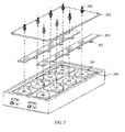
- dielectric TE (transverse electric wave) mode filter dielectric tuning parts 203 and sliding members 204 are added between a cavity 201 and a cover 202.
- cavity perturbation between the dielectric tuning parts 203 and dielectric resonators 206 is achieved, thereby changing the resonance frequency.
- a tuning range of the dielectric filter is relatively small and a tuning range of the dielectric parts is much more limited, the tuning range of such a filter still cannot meet requirements.
- a Chinese patent with an application number of 201110251164.8 discloses a tunable filter, where an inductance coil 302 is wound over a tuning bolt 301, and currents of different directions and magnitudes are supplied to the inductance coil 302 so as to change inductance, thereby achieving cavity perturbation and further achieving tuning.
- this technical solution can achieve a multi-band filtering function without manual tuning, a position where the tuning bolt and the cover are connected is grounded, and applying a voltage nearly has little influence on the inductance of the inductance coil.
- the cavity filter is a typical distributed parameter circuit filter and the inductance coil is a low-frequency lumped parameter component; therefore, it is difficult to tune the cavity resonance frequency by changing a inductance value and a current direction of a lumped parameter inductor at high frequency. As a result, the tuning range of the filter is still small, and cannot meet a requirement of tunable wideband, which results in that platformization cannot be achieved.
- An objective of embodiments of the present invention is to provide a tunable filter, so as to solve a problem that a tuning range of a conventional tunable filter is too small to implement platformization.
- Embodiments of the present invention are implemented as follows: including a plurality of resonance cavities, where each resonance cavity has a resonance tube and a tuning bolt penetrating into space enclosed by the resonance tube; further including a tuning part disposed between the tuning bolt and the resonance tube, where the tuning part and the resonance tube form a first capacitor, and the tuning part and the tuning bolt form a second capacitor; and further including an adjusting structure used for rotating the tuning part, so as to change relative areas between the tuning part and the resonance tube and between the tuning part and the tuning bolt, so that the first capacitor and the second capacitor change synchronously.
- a duplexer including a transmit channel filter and a receive channel filter, where both the transmit channel filter and the receive channel filter perform filtering by using a tunable filter; and the tunable filter includes a plurality of resonance cavities, where each resonance cavity has a resonance tube and a tuning bolt penetrating into space enclosed by the resonance tube; further including a tuning part disposed between the tuning bolt and the resonance tube, where the tuning part and the resonance tube form a first capacitor, and the tuning part and the tuning bolt form a second capacitor; and further including an adjusting structure used for rotating the tuning part, so as to change relative areas between the tuning part and the resonance tube and between the tuning part and the tuning bolt, so that the first capacitor and the second capacitor change synchronously.
- a tuning part is disposed between a tuning bolt and a resonance tube, so that the tuning part, together with the resonance tube and the tuning bolt, forms a double-capacitor structure. Synchronous change of the two capacitors can be achieved by rotating the tuning part by using an adjusting structure, so as to change resonance frequency. Because the two capacitors change synchronously, a tuning range of a filter is larger than a conventional frequency tuning range. As a result, a filter and a duplexer can be truly bandwidth-tunable. Products of different frequency can be tuned by a duplexer using the filter according to an actual requirement instead of a large number of duplexers of different frequency sub-bands, which achieves platformization of a duplexer and significantly saves management and manufacturing costs.
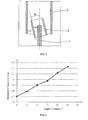
- FIG. 4 is a schematic structural diagram of a single cavity of a tunable filter according to an embodiment of the present invention
- FIG. 5 is a schematic diagram of an operating state of a single cavity of a tunable filter according to an embodiment of the present invention
- FIG. 6 is a schematic diagram of test data of a tunable filter according to an embodiment of the present invention. For ease of description, only parts related to the embodiments are shown.
- the tunable filter includes a plurality of resonance cavities 1, where a resonance tube 2 and a tuning bolt 3 are disposed in each resonance cavity 1, and the tuning bolt 3 penetrates into space enclosed by the resonance tube 2.
- a tuning part 4 is also disposed between the tuning bolt 3 and the resonance tube 2.
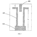
- the resonance tube 2 is equivalent to an inductor L
- an exterior wall of the tuning part 4 and an interior wall of the resonance tube 2 are equivalent to a capacitor (a first capacitor) C 1
- an interior wall of the tuning part 4 and an exterior surface of the tuning bolt 3 are equivalent to another capacitor (a second capacitor) C 2 .
- the tuning part 4, together with the resonance tube 2 and the tuning bolt 3, forms a parallel double-capacitor structure.
- the resonance tube 2, the turning screw 3, and the tuning part 4 cooperate to form a resonance unit that has a filtering function.
- the tunable filter further includes an adjusting structure 5 used for rotating the tuning part 4, so as to change relative areas between the tuning part 4 and the resonance tube 2 and between the tuning part 4 and the tuning bolt 3.
- the tuning part 4 may have a plurality of rotating directions, and the relative areas are changed as long as a central axis of the tuning part 4 rotates relative to central axes of the tuning bolt 3 and the resonance tube 2.
- the tuning part 4 in the embodiment of the present invention is driven by the adjusting structure 5 to rotate in any direction relative to a tuning bolt 3 and a resonance tube 2.
- the tuning part 4 rotates by a certain angle ⁇ , both the relative areas and distances between the tuning part 4 and the resonance tube 2 and between the tuning part 4 and the tuning bolt 3 change, so that the first capacitor C 1 and the second capacitor C 2 change simultaneously, so as to achieve an objective of changing the resonance frequency Fr .
- Different resonance frequency Fr may be obtained by rotating the tuning part 4 by different angles.
- Table 1 Contrast data of angle of rotation of the tuning part and the resonance frequency of the single cavity Angle of rotation (°) 0 15 25 Resonance frequency (GHz) 1.703 1.98 2.23
- the swinging angle in the foregoing data is defined as follows: When the tuning part 4, the tuning bolt 3 and the resonance tube 2 are coaxial, the position of the tuning part 4 is taken as an initial position, and after the tuning part 4 rotates by a certain angle, a deflection angle of the central axis of the tuning part 4 relative to the initial position is the angle of rotation.
- the rotation of the tuning part 4 may be a reciprocating motion and is not limited to rotation in a same direction; therefore, it may be defined that the angle of rotation has a positive value when the tuning part 4 rotates in one direction, and the angle of rotation has a negative value when the tuning part 4 rotates in an opposite direction.
- the foregoing data only records data when the tuning part rotates in a same direction; however, a tunable wideband can also be achieved when the tuning part rotates in an opposite direction. Detailed data thereof is not listed in this embodiment.
- the resonance frequency of the tuning part 4 increases continuously in a range from 1.703 GHz to 2.23 GHz.
- Such a wide frequency tuning range can satisfy band requirements of services such as DCS, PCS, TD-SCDMA and UMTS.
- the foregoing data is only test data of a specific embodiment of the present invention.
- the embodiment of the present invention focuses on the variable tuning range of the filter, and for a specific resonance frequency value, a proper adjustment may be made according to an actual requirement. For example, a resonance frequency of 1.5 to 2.0 GHz is actually required, an initial setting may be properly performed for the structures, relative positions and the like of the resonance tube 2, the tuning bolt 3 and the tuning part 4, and different resonance frequencies may be obtained by adjusting the tuning part 4 during practical operation.
- the tuning part is disposed between the tuning bolt 3 and the resonance tube 2, so as to form a double-capacitor structure. Synchronous change of the two capacitors can be implemented by using the adjusting structure 5 to rotate the tuning part 4, so as to change the resonance frequency. Because the two capacitors change simultaneously, the tuning range of the frequency of the filter is larger than the frequency tuning range of a conventional filter, so that a wideband tuning range of the filter and the duplexer is actually achieved. During practical use, products of different bands can be tuned by one duplexer, so that the duplexer is applicable to a plurality of scenarios, which thereby implements platformization of the duplexer and significantly saves management and manufacturing costs.
- the filter has a simple structure, and does not need addition of a complex device and control unit, thereby effectively controlling increase of production cost. Besides, because synchronous change of the two capacitors can be achieved by rotating the tuning part in any direction and the rotating fulcrum of the tuning part does not need to be strictly limited, the tuning part is freer in rotation and more flexible in design, and manufacturing is more convenient. Moreover, due to the simple structure, the filter is easier to operate and maintain, which thereby further facilitates platformization of the duplexer.
- the resonance tube 2, the tuning part 4, and the tuning bolt 3 may have various specific shapes.
- the shape of the resonance tube 2 may use, but be not limited to, a round-barrel-shape or a polygonal-barrel-shape.
- the shape of the tuning part 4 may also use the foregoing shapes, or may be a barrel shape with a longitudinal opening.
- the shape of the tuning bolt 3 also does not need to be strictly limited. Specific shapes of the three shapes may be properly designed according to an actual requirement and based on the manufacturing difficultly as long as they can form the double-capacitor structure.
- the shapes of the tuning part 4, the resonance tube 2, and the tuning bolt 3 adapt to each other, which can ensure that two electrodes of the first capacitor are parallel to those of the second capacitor, so as to maximize the capacitance and thereby widen the variable range of the capacitor and facilitating manufacturing.
- the tuning bolt 3 is cylindrical, and both the tuning part 4 and the resonance tube 2 are round-barrel-shaped.
- the three are preferably disposed coaxially. In this way, no matter in which direction the tuning part 4 rotates, as long as angles of rotation are the same, changes of the relative areas and distances are the same, and therefore, changes of the resonance frequency are also the same, If the three do not use the foregoing shapes, for example, the three are all polygonal-cylinder-shaped or the three use different shapes, when the tuning part 4 rotates in different directions, changes of the relative areas and distances may not be the same, that is for different rotating directions, correspondence relationships between the angle of rotation and the resonance frequency are not the same, but the wideband tuning range of the filter is not affected.
- the tuning bolt 3 is designed as cylindrical, both the tuning part 4 and the resonance tube 2 are designed as round-barrel-shaped, and the three are coaxial.
- manufacturing is facilitated and design flexibility is improved.
- the tuning effect of the tuning part 4 remains unchanged, which is conducive to maintaining stable operation performance of the tuning part 4 and is convenient for use and maintenance.
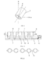
- the tuning part 4 may have various rotating directions. Specifically, referring to a three-dimensional coordinate system shown in FIG. 7, FIG. 8 , and FIG. 9 , Z axis corresponds to a central axis of the tuning part 4 in an initial position.
- the tuning part 4 may rotate in a plane where X axis and Z axis are located, as shown in FIG. 7 .
- the tuning part 4 may rotate in a plane where Y axis and Z axis are located, as shown in FIG. 8 .
- the tuning part 4 may rotate in a plane which presents an angle of 45° to the plane where Y axis and Z axis are located and to the plane where X axis and Z axis are located, as shown in FIG. 9 .
- the rotation may also be in another plane where the relative areas and distances between the tuning part 4 and the resonance tube 2 and between the tuning part 4 and the tuning bolt 3 can also be changed, thereby changing the first capacitor and the second capacitor.
- the number and arrangement manner of the resonance cavities 1 may be determined according to an actual requirement without a strict limitation.
- a plurality of resonance cavities 1 may be arranged in a row by means of straight cavity layout, that is, straight cavity arrangement, as shown in FIG. 10 .
- This arrangement manner facilitates manufacturing, and makes it convenient to dispose the tuning part 4 and control swinging of the tuning part 4.
- the adjusting structure 5 specifically may include a connecting rod 51.
- This structure is suitable for the filter using the straight cavity arrangement. Ends, which are exposed outside the resonance tube 2, of a plurality of tuning parts 4 may be connected in sequence by the connecting rod 51 to form an integral structure.
- the connecting rod 51 is rotatable about its central axis to drive the tuning part 4 to rotate.
- the central axis of the connecting rod 51 may be orthogonal to the central axis of the tuning part 4, that is, the two intersect and are perpendicular.
- the tuning part 4 and the tuning bolt 3 are generally disposed coaxially, and the central axis of the connecting rod 51 is also orthogonal to the central axis of the tuning bolt 3.
- the center of gravity of the tuning part 4 is located exactly above the connecting rod 51, which is conducive to maintaining stability of the tuning part 4, facilitates adjusting the rotation of the tuning part 4, and makes it convenient to establish a correspondence relationship between the angle of rotation and the tuning frequency in the manufacturing stage.
- the adjusting structure 5 may further include a driving unit 52 connected to one end of the connecting rod 51 to drive the connecting rod 51 to rotate in an axial direction, so as to drive the plurality of tuning parts 4 to rotate simultaneously.
- This control unit has a simple structure and is easy to operate.
- the driving unit 52 may use a stepper motor or a gear transmission control mechanism, and may be any unit that can drive the connecting rod 51 to rotate around its central axis.
- the adjusting apparatus 5 in the embodiment of the present invention is not limited to the foregoing structure, and other proper designs may also be made according to an actual requirement, as long as the adjusting structure can enable the tuning part 4 to swing relative to the resonance tube 2 and the tuning bolt 3.
- the swinging angle range of the tuning part 4 may be determined according to an actual requirement.
- the angle of rotation is excessively large, contact with the tuning bolt 3 or the resonance tube 2 may occur, resulting in short circuit.
- the angle of rotation is excessively small, the frequency tuning range is too small to satisfy the requirement for a wideband tuning range.
- the angle of rotation of the tuning part 4 may be limited to -45° to 45°. It can be known from the data recorded in Table 1 that in a rotating range of 0° to 25°, the resonance frequency can satisfy the band requirements of DCS, PCS, TD-SCDMA and UMTS, and in this case, if the angle of rotation is increased to 45°, the resonance range of the filter can be further increased, so that the filter has a wider tuning range and is applicable to more application scenarios. It can be understood that during the rotation of the tuning part 4 in a forward direction and a reverse direction, the adjustment effects of the tuning part 4 are symmetrical. That is, the effects of adjusting from 0° to 45° and adjusting from 0° to -45° are the same, and definitely, the effects of adjusting from 45° to 0° and from -45° to 0° are also the same.
- two notches 41 of the tuning part 4 that are opposite to each other are formed at one end which is hidden inside the resonance tube 2, and an axis of the two notches 41 is consistent with a rotatable direction of the tuning part 4.
- the notch 41 can provide a certain safety margin for the tuning bolt 3, so as to avoid contact between the tuning bolt 3 and the tuning part 4 and thereby further improve stability and safety of the filter.
- width of the notches 41 may be slightly larger than diameter of the tuning bolt 3, and the height may be determined according to a preset angle of rotation, so as to ensure the tuning bolt 3 does not contact bottoms of the notches 41.
- the tuning part 4 and the tuning bolt 3 may use a metal material, so as to provide a wider tuning range.
- the filter may further include a first cover 6 and a second cover 7 disposed opposite to each other. As shown in FIG. 4 , the resonance tube 2 and the tuning bolt 3 are fastened onto the first cover 6 and the second cover 7 respectively.
- the second cover 7 is movable along a central axis of the tuning bolt 3 to change a depth by which the tuning bolt 3 is inserted into the resonance tube 2, so as to change the second capacitor, thereby changing the resonance frequency.
- the resonance tube 2 and the tuning bolt 3 may be fastened onto the respective covers by using screws or other parts.
- the second cover 7 may move under the control of a corresponding control apparatus, and specifically, an existing control manner may be used, which is not described in detail herein.
- the filter has a housing 8, as shown in FIG. 10 .
- space enclosed by the housing may be divided into a plurality of resonance cavities 1 by using any component.
- Each resonance cavity 1 has a resonance unit formed by the resonance tube 2, the tuning part 4, and the tuning bolt 3.
- a specific cavity design manner does not need to be specifically limited.
- the first cover 6 and the second cover 7 may be two opposite surfaces of the housing 8, and may also be two cover plates additionally provided in the housing 8, but the present invention is not limited thereto.
- the tuning part 4 is additionally disposed between the resonance tube 2 and the tuning bolt 3, so as to form a double-capacitor structure.
- the adjusting structure 5 to drive the tuning part 4 to rotate relative to the resonance tube 2 and the tuning bolt 3, the objective of changing the two capacitors synchronously to change the resonance frequency is achieved.
- the filter with two capacitors that change synchronously has a wider tuning range.
- the tuning range of the filter can also be increased by 50%.
- a duplexer using the filter can satisfy the tuning requirement of a wide band, which is of great significance to achieving platformization of a duplexer and reducing management and manufacturing costs.
Landscapes
- Physics & Mathematics (AREA)
- Electromagnetism (AREA)
- Control Of Motors That Do Not Use Commutators (AREA)
Applications Claiming Priority (2)
| Application Number | Priority Date | Filing Date | Title |
|---|---|---|---|
| CN201210132184.8A CN102683773B (zh) | 2012-04-28 | 2012-04-28 | 一种可调滤波器及包括该滤波器的双工器 |
| PCT/CN2012/086836 WO2013159545A1 (zh) | 2012-04-28 | 2012-12-18 | 一种可调滤波器及包括该滤波器的双工器 |
Publications (3)
| Publication Number | Publication Date |
|---|---|
| EP2833473A1 true EP2833473A1 (de) | 2015-02-04 |
| EP2833473A4 EP2833473A4 (de) | 2015-04-15 |
| EP2833473B1 EP2833473B1 (de) | 2016-05-18 |
Family
ID=46815374
Family Applications (1)
| Application Number | Title | Priority Date | Filing Date |
|---|---|---|---|
| EP12874984.3A Not-in-force EP2833473B1 (de) | 2012-04-28 | 2012-12-18 | Abstimmbares filter und duplexer mit dem abstimmbaren filter |
Country Status (4)
| Country | Link |
|---|---|
| US (1) | US9647307B2 (de) |
| EP (1) | EP2833473B1 (de) |
| CN (1) | CN102683773B (de) |
| WO (1) | WO2013159545A1 (de) |
Cited By (1)
| Publication number | Priority date | Publication date | Assignee | Title |
|---|---|---|---|---|
| EP3711113B1 (de) * | 2017-11-16 | 2024-01-17 | RF Microtech S.r.l. | Abstimmbarer bandpassfilter |
Families Citing this family (15)
| Publication number | Priority date | Publication date | Assignee | Title |
|---|---|---|---|---|
| CN102683773B (zh) | 2012-04-28 | 2014-07-09 | 华为技术有限公司 | 一种可调滤波器及包括该滤波器的双工器 |
| CN104969411B (zh) * | 2013-10-10 | 2017-09-12 | 华为技术有限公司 | 滤波器及应用其的通信模块 |
| CN103700912B (zh) * | 2013-12-31 | 2016-06-08 | 深圳市大富科技股份有限公司 | 腔体滤波器及其盖板 |
| US9899716B1 (en) * | 2015-03-01 | 2018-02-20 | Telefonaktiebolaget Lm Ericsson (Publ) | Waveguide E-plane filter |
| KR101756124B1 (ko) * | 2015-11-30 | 2017-07-11 | 주식회사 케이엠더블유 | 크로스 커플링 노치 구조를 구비한 캐비티 타입의 무선 주파수 필터 |
| TWI630330B (zh) | 2016-11-15 | 2018-07-21 | 財團法人工業技術研究院 | 智慧機械元件 |
| CN109103554A (zh) * | 2017-06-21 | 2018-12-28 | 罗森伯格技术(昆山)有限公司 | 可调波导滤波器 |
| CN109585989B (zh) * | 2017-09-29 | 2025-05-30 | 普罗斯通信技术(苏州)有限公司 | 一种可调波导滤波器及其调谐方法 |
| CN113131898A (zh) * | 2019-12-30 | 2021-07-16 | 深圳市大富科技股份有限公司 | 一种滤波器及通信设备 |
| CN111987397A (zh) * | 2020-07-05 | 2020-11-24 | 苏州诺泰信通讯有限公司 | 一种倒装式滤波器结构 |
| CN112072237B (zh) * | 2020-08-27 | 2021-12-03 | 电子科技大学 | 一种陶瓷/空气复合介质可调腔体滤波器 |
| CN113725569A (zh) * | 2021-09-13 | 2021-11-30 | 宁波华瓷通信技术股份有限公司 | 一种滤波器耦合量增强结构 |
| CN116864943A (zh) * | 2023-07-03 | 2023-10-10 | 南方科技大学 | 可调双工器 |
| CN117117447A (zh) * | 2023-08-01 | 2023-11-24 | 苏州诺泰信通讯有限公司 | 谐振柱位置可变的窗口耦合结构 |
| CN117713727A (zh) * | 2023-12-21 | 2024-03-15 | 福建星海通信科技有限公司 | 一种高q小型化加载分布式电容的谐振腔结构 |
Family Cites Families (26)
| Publication number | Priority date | Publication date | Assignee | Title |
|---|---|---|---|---|
| US2402443A (en) * | 1941-08-26 | 1946-06-18 | Rca Corp | Resonant line and associated circuits |
| CH303063A (de) * | 1952-06-20 | 1954-11-15 | Patelhold Patentverwertung | Bandpassfilter für Mikrowellen mit verschiebbarem Durchlassbereich. |
| US3252116A (en) * | 1963-12-17 | 1966-05-17 | Rca Corp | Combined tuning and stabilization means for cavity resonators |
| DE2236955A1 (de) * | 1971-07-30 | 1973-02-08 | Cossor Ltd A C | Hohlraumfilter |
| JPS55100701A (en) * | 1979-01-26 | 1980-07-31 | Matsushita Electric Ind Co Ltd | Coaxial resonator |
| SU974431A1 (ru) * | 1979-09-25 | 1982-11-15 | Предприятие П/Я В-2518 | Трехэлектродный конденсатор переменной емкости |
| FR2477783A1 (fr) * | 1980-03-04 | 1981-09-11 | Thomson Csf | Dispositif d'accord a capacite variable et filtre hyperfrequences accordable comportant au moins un tel dispositif |
| JPS57136802A (en) * | 1981-02-17 | 1982-08-24 | Matsushita Electric Ind Co Ltd | Coaxial filter |
| JPS58111404A (ja) * | 1981-12-24 | 1983-07-02 | Matsushita Electric Ind Co Ltd | 同軸型フイルタ |
| FR2635620B1 (fr) | 1988-08-19 | 1991-08-02 | Radiotechnique Compelec | Circuit d'entree a commutation acceleree |
| JPH077449A (ja) * | 1993-06-17 | 1995-01-10 | Oki Electric Ind Co Ltd | アンテナ切り替えスイッチ |
| US5682128A (en) * | 1996-04-23 | 1997-10-28 | Illinois Superconductor Corporation | Superconducting reentrant resonator |
| FI973842A7 (fi) * | 1997-09-30 | 1999-03-31 | Fertron Oy | Koaksiaaliresonaattori |
| US6081175A (en) * | 1998-09-11 | 2000-06-27 | Radio Frequency Systems Inc. | Coupling structure for coupling cavity resonators |
| JP2003318603A (ja) * | 2002-04-19 | 2003-11-07 | Kobe Steel Ltd | 高周波フィルタ |
| KR100769657B1 (ko) * | 2003-08-23 | 2007-10-23 | 주식회사 케이엠더블유 | 무선 주파수 대역 가변 필터 |
| US7456711B1 (en) | 2005-11-09 | 2008-11-25 | Memtronics Corporation | Tunable cavity filters using electronically connectable pieces |
| CN101743040B (zh) | 2007-05-14 | 2013-04-03 | 帕奥罗·纳尔奇斯 | 鼻腔滤器 |
| EP2031693B1 (de) | 2007-08-28 | 2014-04-30 | ACE Technology | Frequenzabstimmbarer Filter |
| GB0721361D0 (en) * | 2007-10-30 | 2007-12-12 | Radio Design Ltd | Tunable filter |
| CN201117780Y (zh) * | 2007-11-12 | 2008-09-17 | 摩比天线技术(深圳)有限公司 | 一种同轴腔体谐振器间的耦合结构 |
| KR101094762B1 (ko) * | 2009-05-12 | 2011-12-16 | 주식회사 알림테크놀러지 | 이중 공진기 구조의 rf 필터 |
| GB2478938A (en) * | 2010-03-24 | 2011-09-28 | Gary Raymond Cobb | Coupled transmission line resonator band-pass filter with transversely rotated resonators for improved selectivity |
| CN101820091B (zh) | 2010-04-29 | 2013-07-03 | 罗森伯格(上海)通信技术有限公司 | 可调腔体滤波器 |
| CN102324601A (zh) | 2011-08-29 | 2012-01-18 | 摩比天线技术(深圳)有限公司 | 一种可调滤波器 |
| CN102683773B (zh) * | 2012-04-28 | 2014-07-09 | 华为技术有限公司 | 一种可调滤波器及包括该滤波器的双工器 |
-
2012
- 2012-04-28 CN CN201210132184.8A patent/CN102683773B/zh not_active Expired - Fee Related
- 2012-12-18 WO PCT/CN2012/086836 patent/WO2013159545A1/zh not_active Ceased
- 2012-12-18 EP EP12874984.3A patent/EP2833473B1/de not_active Not-in-force
-
2014
- 2014-10-27 US US14/524,400 patent/US9647307B2/en not_active Expired - Fee Related
Cited By (1)
| Publication number | Priority date | Publication date | Assignee | Title |
|---|---|---|---|---|
| EP3711113B1 (de) * | 2017-11-16 | 2024-01-17 | RF Microtech S.r.l. | Abstimmbarer bandpassfilter |
Also Published As
| Publication number | Publication date |
|---|---|
| CN102683773A (zh) | 2012-09-19 |
| CN102683773B (zh) | 2014-07-09 |
| EP2833473A4 (de) | 2015-04-15 |
| US20150042413A1 (en) | 2015-02-12 |
| EP2833473B1 (de) | 2016-05-18 |
| US9647307B2 (en) | 2017-05-09 |
| WO2013159545A1 (zh) | 2013-10-31 |
Similar Documents
| Publication | Publication Date | Title |
|---|---|---|
| EP2833473B1 (de) | Abstimmbares filter und duplexer mit dem abstimmbaren filter | |
| EP3062386B1 (de) | Resonator, filter, duplexer und multiplexer | |
| CN1717838B (zh) | 谐振器滤波器 | |
| US6147577A (en) | Tunable ceramic filters | |
| AU701389B2 (en) | Double helix antenna system | |
| DE602006000444T2 (de) | Aus dielektrischem material hergestellter, mit diskreten spannungen abstimmbarer resonator | |
| CN102324602A (zh) | 用于TE01δ模介质谐振器的电感耦合装置 | |
| CN109888444A (zh) | 可调滤波器及可调双工器 | |
| US20110133862A1 (en) | Tunable filter capable of controlling tuning characteristics | |
| EP2203953B1 (de) | Einstellbarer filter und verfahren zu seiner verwendung | |
| CN109244619B (zh) | 折叠腔体介质加载可调滤波器、双工器 | |
| CN108448215A (zh) | 一种c波段电调腔体滤波器 | |
| CN105070987B (zh) | 一种c波段可调带通滤波器 | |
| US5285178A (en) | Combiner resonator having an I-beam shaped element disposed within its cavity | |
| CN211320278U (zh) | 一种可调滤波器 | |
| CN102723569B (zh) | 一种可调谐振腔 | |
| EP3207587B1 (de) | Elektrisch abstimmbare wellenleiterstruktur | |
| CN103117431A (zh) | 一种腔体高通滤波器 | |
| US11431068B2 (en) | Frequency variable filter and coupling method | |
| CN203760601U (zh) | 基于刻蚀五角星形槽的圆形贴片谐振器的可切换微带带通滤波器 | |
| WO2019109735A1 (zh) | 一种可调带宽的波导滤波器 | |
| CN203760605U (zh) | 一种新型结构的可切换微带带通滤波器 | |
| Mao et al. | A Frequency Reconfigurable Band-pass Filter Based on Microstrip Open-Loop Hole Resonator | |
| You et al. | Reconfigurable Cavity Filter Using Coplanar Microstrip Feeding Network | |
| CN203760604U (zh) | 基于刻蚀矩形槽的圆形贴片谐振器的可切换微带带通滤波器 |
Legal Events
| Date | Code | Title | Description |
|---|---|---|---|
| PUAI | Public reference made under article 153(3) epc to a published international application that has entered the european phase |
Free format text: ORIGINAL CODE: 0009012 |
|
| 17P | Request for examination filed |
Effective date: 20141030 |
|
| AK | Designated contracting states |
Kind code of ref document: A1 Designated state(s): AL AT BE BG CH CY CZ DE DK EE ES FI FR GB GR HR HU IE IS IT LI LT LU LV MC MK MT NL NO PL PT RO RS SE SI SK SM TR |
|
| AX | Request for extension of the european patent |
Extension state: BA ME |
|
| RA4 | Supplementary search report drawn up and despatched (corrected) |
Effective date: 20150312 |
|
| RIC1 | Information provided on ipc code assigned before grant |
Ipc: H01P 1/205 20060101AFI20150306BHEP |
|
| DAX | Request for extension of the european patent (deleted) | ||
| REG | Reference to a national code |
Ref country code: DE Ref legal event code: R079 Ref document number: 602012018854 Country of ref document: DE Free format text: PREVIOUS MAIN CLASS: H01P0001205000 Ipc: H01P0001208000 |
|
| GRAP | Despatch of communication of intention to grant a patent |
Free format text: ORIGINAL CODE: EPIDOSNIGR1 |
|
| RIC1 | Information provided on ipc code assigned before grant |
Ipc: H01P 1/208 20060101AFI20151117BHEP |
|
| INTG | Intention to grant announced |
Effective date: 20151204 |
|
| RIN1 | Information on inventor provided before grant (corrected) |
Inventor name: ZHOU, YANZHAO |
|
| GRAS | Grant fee paid |
Free format text: ORIGINAL CODE: EPIDOSNIGR3 |
|
| GRAA | (expected) grant |
Free format text: ORIGINAL CODE: 0009210 |
|
| AK | Designated contracting states |
Kind code of ref document: B1 Designated state(s): AL AT BE BG CH CY CZ DE DK EE ES FI FR GB GR HR HU IE IS IT LI LT LU LV MC MK MT NL NO PL PT RO RS SE SI SK SM TR |
|
| REG | Reference to a national code |
Ref country code: GB Ref legal event code: FG4D |
|
| REG | Reference to a national code |
Ref country code: CH Ref legal event code: EP |
|
| REG | Reference to a national code |
Ref country code: IE Ref legal event code: FG4D Ref country code: AT Ref legal event code: REF Ref document number: 801163 Country of ref document: AT Kind code of ref document: T Effective date: 20160615 |
|
| REG | Reference to a national code |
Ref country code: DE Ref legal event code: R096 Ref document number: 602012018854 Country of ref document: DE |
|
| REG | Reference to a national code |
Ref country code: NL Ref legal event code: FP |
|
| REG | Reference to a national code |
Ref country code: SE Ref legal event code: TRGR |
|
| REG | Reference to a national code |
Ref country code: LT Ref legal event code: MG4D |
|
| PG25 | Lapsed in a contracting state [announced via postgrant information from national office to epo] |
Ref country code: NO Free format text: LAPSE BECAUSE OF FAILURE TO SUBMIT A TRANSLATION OF THE DESCRIPTION OR TO PAY THE FEE WITHIN THE PRESCRIBED TIME-LIMIT Effective date: 20160818 Ref country code: LT Free format text: LAPSE BECAUSE OF FAILURE TO SUBMIT A TRANSLATION OF THE DESCRIPTION OR TO PAY THE FEE WITHIN THE PRESCRIBED TIME-LIMIT Effective date: 20160518 Ref country code: FI Free format text: LAPSE BECAUSE OF FAILURE TO SUBMIT A TRANSLATION OF THE DESCRIPTION OR TO PAY THE FEE WITHIN THE PRESCRIBED TIME-LIMIT Effective date: 20160518 |
|
| REG | Reference to a national code |
Ref country code: FR Ref legal event code: PLFP Year of fee payment: 5 |
|
| REG | Reference to a national code |
Ref country code: AT Ref legal event code: MK05 Ref document number: 801163 Country of ref document: AT Kind code of ref document: T Effective date: 20160518 |
|
| PG25 | Lapsed in a contracting state [announced via postgrant information from national office to epo] |
Ref country code: RS Free format text: LAPSE BECAUSE OF FAILURE TO SUBMIT A TRANSLATION OF THE DESCRIPTION OR TO PAY THE FEE WITHIN THE PRESCRIBED TIME-LIMIT Effective date: 20160518 Ref country code: GR Free format text: LAPSE BECAUSE OF FAILURE TO SUBMIT A TRANSLATION OF THE DESCRIPTION OR TO PAY THE FEE WITHIN THE PRESCRIBED TIME-LIMIT Effective date: 20160819 Ref country code: HR Free format text: LAPSE BECAUSE OF FAILURE TO SUBMIT A TRANSLATION OF THE DESCRIPTION OR TO PAY THE FEE WITHIN THE PRESCRIBED TIME-LIMIT Effective date: 20160518 Ref country code: LV Free format text: LAPSE BECAUSE OF FAILURE TO SUBMIT A TRANSLATION OF THE DESCRIPTION OR TO PAY THE FEE WITHIN THE PRESCRIBED TIME-LIMIT Effective date: 20160518 Ref country code: ES Free format text: LAPSE BECAUSE OF FAILURE TO SUBMIT A TRANSLATION OF THE DESCRIPTION OR TO PAY THE FEE WITHIN THE PRESCRIBED TIME-LIMIT Effective date: 20160518 Ref country code: PT Free format text: LAPSE BECAUSE OF FAILURE TO SUBMIT A TRANSLATION OF THE DESCRIPTION OR TO PAY THE FEE WITHIN THE PRESCRIBED TIME-LIMIT Effective date: 20160919 |
|
| PG25 | Lapsed in a contracting state [announced via postgrant information from national office to epo] |
Ref country code: RO Free format text: LAPSE BECAUSE OF FAILURE TO SUBMIT A TRANSLATION OF THE DESCRIPTION OR TO PAY THE FEE WITHIN THE PRESCRIBED TIME-LIMIT Effective date: 20160518 Ref country code: EE Free format text: LAPSE BECAUSE OF FAILURE TO SUBMIT A TRANSLATION OF THE DESCRIPTION OR TO PAY THE FEE WITHIN THE PRESCRIBED TIME-LIMIT Effective date: 20160518 Ref country code: SK Free format text: LAPSE BECAUSE OF FAILURE TO SUBMIT A TRANSLATION OF THE DESCRIPTION OR TO PAY THE FEE WITHIN THE PRESCRIBED TIME-LIMIT Effective date: 20160518 Ref country code: DK Free format text: LAPSE BECAUSE OF FAILURE TO SUBMIT A TRANSLATION OF THE DESCRIPTION OR TO PAY THE FEE WITHIN THE PRESCRIBED TIME-LIMIT Effective date: 20160518 Ref country code: CZ Free format text: LAPSE BECAUSE OF FAILURE TO SUBMIT A TRANSLATION OF THE DESCRIPTION OR TO PAY THE FEE WITHIN THE PRESCRIBED TIME-LIMIT Effective date: 20160518 |
|
| REG | Reference to a national code |
Ref country code: DE Ref legal event code: R097 Ref document number: 602012018854 Country of ref document: DE |
|
| PG25 | Lapsed in a contracting state [announced via postgrant information from national office to epo] |
Ref country code: AT Free format text: LAPSE BECAUSE OF FAILURE TO SUBMIT A TRANSLATION OF THE DESCRIPTION OR TO PAY THE FEE WITHIN THE PRESCRIBED TIME-LIMIT Effective date: 20160518 Ref country code: BE Free format text: LAPSE BECAUSE OF FAILURE TO SUBMIT A TRANSLATION OF THE DESCRIPTION OR TO PAY THE FEE WITHIN THE PRESCRIBED TIME-LIMIT Effective date: 20160518 Ref country code: SM Free format text: LAPSE BECAUSE OF FAILURE TO SUBMIT A TRANSLATION OF THE DESCRIPTION OR TO PAY THE FEE WITHIN THE PRESCRIBED TIME-LIMIT Effective date: 20160518 Ref country code: PL Free format text: LAPSE BECAUSE OF FAILURE TO SUBMIT A TRANSLATION OF THE DESCRIPTION OR TO PAY THE FEE WITHIN THE PRESCRIBED TIME-LIMIT Effective date: 20160518 |
|
| PLBE | No opposition filed within time limit |
Free format text: ORIGINAL CODE: 0009261 |
|
| STAA | Information on the status of an ep patent application or granted ep patent |
Free format text: STATUS: NO OPPOSITION FILED WITHIN TIME LIMIT |
|
| 26N | No opposition filed |
Effective date: 20170221 |
|
| PG25 | Lapsed in a contracting state [announced via postgrant information from national office to epo] |
Ref country code: SI Free format text: LAPSE BECAUSE OF FAILURE TO SUBMIT A TRANSLATION OF THE DESCRIPTION OR TO PAY THE FEE WITHIN THE PRESCRIBED TIME-LIMIT Effective date: 20160518 |
|
| PG25 | Lapsed in a contracting state [announced via postgrant information from national office to epo] |
Ref country code: MC Free format text: LAPSE BECAUSE OF FAILURE TO SUBMIT A TRANSLATION OF THE DESCRIPTION OR TO PAY THE FEE WITHIN THE PRESCRIBED TIME-LIMIT Effective date: 20160518 |
|
| REG | Reference to a national code |
Ref country code: CH Ref legal event code: PL |
|
| REG | Reference to a national code |
Ref country code: IE Ref legal event code: MM4A |
|
| PG25 | Lapsed in a contracting state [announced via postgrant information from national office to epo] |
Ref country code: LI Free format text: LAPSE BECAUSE OF NON-PAYMENT OF DUE FEES Effective date: 20161231 Ref country code: CH Free format text: LAPSE BECAUSE OF NON-PAYMENT OF DUE FEES Effective date: 20161231 Ref country code: LU Free format text: LAPSE BECAUSE OF NON-PAYMENT OF DUE FEES Effective date: 20161218 |
|
| REG | Reference to a national code |
Ref country code: FR Ref legal event code: PLFP Year of fee payment: 6 |
|
| PG25 | Lapsed in a contracting state [announced via postgrant information from national office to epo] |
Ref country code: IE Free format text: LAPSE BECAUSE OF NON-PAYMENT OF DUE FEES Effective date: 20161218 |
|
| PG25 | Lapsed in a contracting state [announced via postgrant information from national office to epo] |
Ref country code: HU Free format text: LAPSE BECAUSE OF FAILURE TO SUBMIT A TRANSLATION OF THE DESCRIPTION OR TO PAY THE FEE WITHIN THE PRESCRIBED TIME-LIMIT; INVALID AB INITIO Effective date: 20121218 |
|
| PG25 | Lapsed in a contracting state [announced via postgrant information from national office to epo] |
Ref country code: MK Free format text: LAPSE BECAUSE OF FAILURE TO SUBMIT A TRANSLATION OF THE DESCRIPTION OR TO PAY THE FEE WITHIN THE PRESCRIBED TIME-LIMIT Effective date: 20160518 Ref country code: IS Free format text: LAPSE BECAUSE OF FAILURE TO SUBMIT A TRANSLATION OF THE DESCRIPTION OR TO PAY THE FEE WITHIN THE PRESCRIBED TIME-LIMIT Effective date: 20160518 Ref country code: CY Free format text: LAPSE BECAUSE OF FAILURE TO SUBMIT A TRANSLATION OF THE DESCRIPTION OR TO PAY THE FEE WITHIN THE PRESCRIBED TIME-LIMIT Effective date: 20160518 |
|
| PG25 | Lapsed in a contracting state [announced via postgrant information from national office to epo] |
Ref country code: BG Free format text: LAPSE BECAUSE OF FAILURE TO SUBMIT A TRANSLATION OF THE DESCRIPTION OR TO PAY THE FEE WITHIN THE PRESCRIBED TIME-LIMIT Effective date: 20160518 |
|
| PG25 | Lapsed in a contracting state [announced via postgrant information from national office to epo] |
Ref country code: MT Free format text: LAPSE BECAUSE OF NON-PAYMENT OF DUE FEES Effective date: 20161218 |
|
| PG25 | Lapsed in a contracting state [announced via postgrant information from national office to epo] |
Ref country code: TR Free format text: LAPSE BECAUSE OF FAILURE TO SUBMIT A TRANSLATION OF THE DESCRIPTION OR TO PAY THE FEE WITHIN THE PRESCRIBED TIME-LIMIT Effective date: 20160518 Ref country code: AL Free format text: LAPSE BECAUSE OF FAILURE TO SUBMIT A TRANSLATION OF THE DESCRIPTION OR TO PAY THE FEE WITHIN THE PRESCRIBED TIME-LIMIT Effective date: 20160518 |
|
| PGFP | Annual fee paid to national office [announced via postgrant information from national office to epo] |
Ref country code: NL Payment date: 20231116 Year of fee payment: 12 |
|
| PGFP | Annual fee paid to national office [announced via postgrant information from national office to epo] |
Ref country code: GB Payment date: 20231102 Year of fee payment: 12 |
|
| PGFP | Annual fee paid to national office [announced via postgrant information from national office to epo] |
Ref country code: SE Payment date: 20231110 Year of fee payment: 12 Ref country code: IT Payment date: 20231110 Year of fee payment: 12 Ref country code: FR Payment date: 20231108 Year of fee payment: 12 Ref country code: DE Payment date: 20231031 Year of fee payment: 12 |
|
| REG | Reference to a national code |
Ref country code: DE Ref legal event code: R119 Ref document number: 602012018854 Country of ref document: DE |
|
| REG | Reference to a national code |
Ref country code: SE Ref legal event code: EUG |
|
| REG | Reference to a national code |
Ref country code: NL Ref legal event code: MM Effective date: 20250101 |
|
| GBPC | Gb: european patent ceased through non-payment of renewal fee |
Effective date: 20241218 |
|
| PG25 | Lapsed in a contracting state [announced via postgrant information from national office to epo] |
Ref country code: NL Free format text: LAPSE BECAUSE OF NON-PAYMENT OF DUE FEES Effective date: 20250101 |
|
| PG25 | Lapsed in a contracting state [announced via postgrant information from national office to epo] |
Ref country code: DE Free format text: LAPSE BECAUSE OF NON-PAYMENT OF DUE FEES Effective date: 20250701 |
|
| PG25 | Lapsed in a contracting state [announced via postgrant information from national office to epo] |
Ref country code: IT Free format text: LAPSE BECAUSE OF NON-PAYMENT OF DUE FEES Effective date: 20241218 |
|
| PG25 | Lapsed in a contracting state [announced via postgrant information from national office to epo] |
Ref country code: GB Free format text: LAPSE BECAUSE OF NON-PAYMENT OF DUE FEES Effective date: 20241218 |
|
| PG25 | Lapsed in a contracting state [announced via postgrant information from national office to epo] |
Ref country code: FR Free format text: LAPSE BECAUSE OF NON-PAYMENT OF DUE FEES Effective date: 20241231 |