EP3712010A1 - Zurrpunkt mit montagestellung - Google Patents
Zurrpunkt mit montagestellung Download PDFInfo
- Publication number
- EP3712010A1 EP3712010A1 EP19209481.1A EP19209481A EP3712010A1 EP 3712010 A1 EP3712010 A1 EP 3712010A1 EP 19209481 A EP19209481 A EP 19209481A EP 3712010 A1 EP3712010 A1 EP 3712010A1
- Authority
- EP
- European Patent Office
- Prior art keywords
- recess
- eyelet
- cassette
- lashing point
- lashing
- Prior art date
- Legal status (The legal status is an assumption and is not a legal conclusion. Google has not performed a legal analysis and makes no representation as to the accuracy of the status listed.)
- Granted
Links
Images




Classifications
-
- B—PERFORMING OPERATIONS; TRANSPORTING
- B60—VEHICLES IN GENERAL
- B60P—VEHICLES ADAPTED FOR LOAD TRANSPORTATION OR TO TRANSPORT, TO CARRY, OR TO COMPRISE SPECIAL LOADS OR OBJECTS
- B60P7/00—Securing or covering of load on vehicles
- B60P7/06—Securing of load
- B60P7/08—Securing to the vehicle floor or sides
- B60P7/0807—Attachment points
-
- B—PERFORMING OPERATIONS; TRANSPORTING
- B64—AIRCRAFT; AVIATION; COSMONAUTICS
- B64D—EQUIPMENT FOR FITTING IN OR TO AIRCRAFT; FLIGHT SUITS; PARACHUTES; ARRANGEMENT OR MOUNTING OF POWER PLANTS OR PROPULSION TRANSMISSIONS IN AIRCRAFT
- B64D9/00—Equipment for handling freight; Equipment for facilitating passenger embarkation or the like
- B64D9/003—Devices for retaining pallets or freight containers
Definitions
- the present invention relates to a lashing point according to the features in the preamble of claim 1.
- Lashing points count, for example, through the German utility model DE 20 2008 008 418 U1 to the state of the art.
- Such lashing points have a pivot axis for a bracket that can be pulled out of a pocket and moved into a lashing position.
- the load is lashed under tensile load on the bracket, which automatically assumes an angular position in the longitudinal direction of the lashing device.
- a minimum angle to the loading area should not be undercut.
- the bracket should be supported on a rear wall of the lashing point and not on devices on the loading area, such as light grids. This is to avoid damaging the loading area. It has been suggested to crop the back wall so that the Angled bracket comes to rest flat on an upper side of the rear wall.
- a support cam is formed on a rear side of the eyelet body. If the eyelet body is pulled out of the backdrop and brought into a lashing position or use position in the direction of the loading area, the support cam rests on an upper side of the cassette or the loading area, which is why the eyelet body remains in the use position.
- a installing fitter can therefore only use one hand to hook or thread a corresponding hook or other lashing device into the eye of the eye body.
- the object of the present invention is to improve a lashing point with regard to its manufacture and also its handling compared to lashing points known from the prior art.
- the lashing point according to the invention is intended to be arranged on a loading area of a transport vehicle.
- the lashing point can be coupled with a lifting, pulling or lashing means, in that an eyelet body is mounted relatively movably in a cassette and can be pulled out from a rest position in the cassette into a position of use.
- a link guide is formed in laterally arranged link plates.
- the eyelet body itself has laterally protruding arms in a lower area, the arms engaging the link guide. If the eyelet body is from a rest position to a Out of use position, the arms are moved through the backdrop. In particular, this means that, in relation to the vertical direction, the eyelet is pulled up out of the rest position.
- the eyelet body is arranged in a specific position of use in which it is held to connect the lifting, pulling or lashing means, which is called the assembly position.
- this is done in such a way that a depression or indentation is formed in a rear side of the eyelet body.
- the back of the eyelet body is the side of the eyelet body that is oriented towards the loading area.
- the recess rests positively on one edge.
- the edge can be formed on the cassette or the loading area.
- an extension can be provided, the extension itself being formed on the cassette or being formed on the loading area. The extension then engages positively in the recess.
- the depression does not cause any weakening of the eyelet body with regard to its usage properties for lashing to the loading area.
- the fact that the recess can easily be introduced into the eyelet body from a production point of view also improves the manufacture of a lashing point according to the invention compared to the prior art.
- the recess itself can be formed continuously over the entire width of the eyelet body. This is particularly advantageous if the depression comes to rest on an edge.
- the recess itself can, however, also only be designed in a point-like manner or lengthwise. This is advantageous if corresponding extensions engage in the depression.
- Two or more depressions can then be formed next to one another at a distance from one another.
- Corresponding extensions are then preferably also arranged next to one another, which positively engage in the recess.
- the recess is designed in such a way that it is set back with respect to a surface on the rear side which surrounds or borders it or is adjacent. Set back means in the direction of the eyelet body.
- the recess itself is preferably triangular or trough-shaped in cross section, very particularly preferably rectangular.
- the extension is designed in its cross section to correspond in particular to the cross section of the recess, so that in the assembly position a secure hold is ensured by a form fit.
- the recess is arranged on the eyelet body itself below an opening for forming the eyelet.
- the recess is arranged above an axis formed by the arms. This positioning makes it possible, in particular, to support the eyelet body in the assembly position in the area of an edge of the cassette or edge of the loading area.
- Figure 1 shows the lashing point 1 according to the invention in a perspective view in the assembly position.
- An eyelet body 2 is pulled out from a cassette 3.
- the cassette 3 is formed by two lateral link plates 4 and corresponding links 5; a web 6 or back plate connecting the link plates 4 is also arranged.
- Laterally protruding arms 7 of the eyelet body 2 engage in the link 5 and thus guide the eyelet body 2 within the link 5.
- the eyelet body 2 can thus be from the in Figure 1 mounting position shown in Figure 2 shown rest position are brought within the cassette 3 or lowered.
- the eyelet body 2 in the assembly position, this is at least partially pulled out of the cassette 3 and arranged at an angle alpha ⁇ to a loading surface 8.
- the angle alpha ⁇ can preferably be 20 to 40 °, in particular 25 to 35 ° and very particularly preferably be 30 °. Due to the action of gravity, the eyelet body 2 would now slide back into the cassette 3 in the vertical direction V in relation to the image plane.
- Figure 4 which is a longitudinal sectional view according to Figure 3 represents, avoided by a recess 10 is formed on a rear side 9 of the eyelet body 2.
- An extension 11 of the web 6 arranged on the rear side engages in the recess 10 according to the invention in a form-fitting manner and thus holds the eyelet body 2 securely stored in the assembly position shown.
- the recess 10 itself is configured essentially rectangular in its cross section, as is the extension 11.
- the extension 11 is also shown in FIG Figure 2 . It can be seen here that the extension 11 is only formed in sections over the width 14 of the web 6.
- the recess 10 on the rear side 9 of the eyelet body 2 is also formed only lengthwise over the width 14 of the eyelet body 2.
- the recess 10 can, however, also be formed over the entire width 14 of the rear side 9 of the eyelet body 2.
- the entire web 6 is angled, so that the extension 11 is designed to protrude from the web 6, in particular an end face 12 of the web 6.
- FIG. 5 An alternative is shown in Figure 5 .
- the web 6 is designed as a web plate essentially flat or straight.
- the extension 11 is angled so that the extension 11 also engages in a form-fitting manner in the assembly position.
- Figure 6 which shows the first variant, a further position of use can be assumed, shown again in FIG Figure 7a and b.
- Figure 7a shows a side view of Figure 6 .
- Figure 7b shows a corresponding longitudinal sectional view.
- the recess 10 is designed to be set back with respect to the surface or area of the rear side 9 that borders it.
- the eyelet is pivoted outward in relation to an indicated loading surface 8 and protrudes essentially perpendicularly from the cassette 3.
- the recess 10 is set back with respect to the adjacent surface or the area of the rear side 9 surrounding the recess 10.
- the recess 10 is below an opening 13 which forms the eyelet in the eyelet body 2, and above a through the arms 7 formed axis. Further positions of use, not shown, can be assumed due to the pivotability of the eyelet body 2 in the upper position in the link.
- the recess 10 is only formed lengthwise over the width 14 of the eyelet body 2, correspondingly the extension 11 is also formed lengthwise. It is also conceivable, but not shown here in more detail, that two or more depressions 10 are formed next to one another, based on the width.
- the depressions 10 could, for example, also be formed only in the form of points; likewise, as already mentioned above, the depression 10 can be embodied to run over the entire width 14 of the rear side 9.
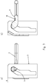
- Figures 9a and b shows a side view and a side sectional view of the lashing point according to the invention.
- the eyelet body 2 has a recess 10 formed on its rear side 9. With this recess 10 it rests on an edge 15 of the loading area 8 in the assembly position. This prevents the eyelet body 2 from being lowered into the rest position.
- a corresponding lashing means can be coupled to the eyelet body 2 without the eyelet body 2 being held separately.
- Figure 9c shows a rear view of the eyelet body 2. It can be seen that the recess 10 extends over the entire width B of the eyelet body 2. The recess 10 itself is arranged at such a height that it is at least partially formed into the opening 13 of the eyelet body 2. The depression 10 can, however, also lie further down to the right in relation to the image plane, so that it would be arranged below the opening of the eyelet body 2.
- the recess 10 according to Figure 9 is designed such that in the area of the recess 10 the eyelet has a smaller thickness D10 than in the area of the rest of the eyelet body 2. This means that the thickness D2 is greater than the thickness D10.
- the recess 10 thus forms a shoulder 16, the shoulder 16 resting on the edge 15 of the loading area 8.
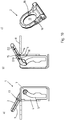
- Figure 10a, b and c show an alternative design variant. This essentially corresponds to that in Figure 9 shown variant.
- a corresponding recess 10 is formed on the rear side 9 of the eyelet body 2.
- This recess 10 of the eyelet body 2 is formed by a bend 17 of the eyelet body 2.
- the thickness of the eyelet body D2 essentially corresponds to the thickness D10 of the eyelet body 2.
- a shoulder 16 is thus also formed, so that the shoulder 16 again rests on the edge 15 of the loading surface 8 in the assembly position.
- the edge 15 can be formed, as shown, by the back plate or the web 6 of the lashing point 1.
- the recess 10 then extends over the entire width of the eyelet body 2.
Landscapes
- Engineering & Computer Science (AREA)
- Aviation & Aerospace Engineering (AREA)
- Transportation (AREA)
- Mechanical Engineering (AREA)
- Hooks, Suction Cups, And Attachment By Adhesive Means (AREA)
- Packaging Of Annular Or Rod-Shaped Articles, Wearing Apparel, Cassettes, Or The Like (AREA)
Abstract
Description
- Die vorliegende Erfindung betrifft einen Zurrpunkt gemäß den Merkmalen im Obergriff von Anspruch 1.
- Zurrpunkte zählen zum Beispiel durch das deutsche Gebrauchsmuster
DE 20 2008 008 418 U1 zum Stand der Technik. Derartige Zurrpunkte besitzen eine Schwenkachse für einen Bügel, der aus einer Tasche herausgezogen und in eine Zurrposition verlagert werden kann. Das Verzurren der Ladung erfolgt unter Zugbelastung des Bügels, der selbsttätig eine Winkellage in Längsrichtung des Zurrmittels einnimmt. Hierbei sollte ein minimaler Winkel zur Ladefläche nicht unterschritten werden. Es ist bekannt, dass sich der Bügel an einer Rückwand des Zurrpunktes abstützen soll und nicht an Einrichtungen auf der Ladefläche, wie zum Beispiel Lichtgitter. Dadurch soll die Beschädigung der Ladefläche vermieden werden. Es ist vorgeschlagen worden, die Rückwand abzukröpfen, damit der abgewinkelte Bügel flächig an einer Oberseite der Rückwand zur Anlage kommt. Allerdings wird der Abstand zwischen der Schwenkachse und der Rückwand dadurch verkleinert. Bei einer Zugbelastung, die einem Winkel kleiner als dem minimal einstellbaren Winkel des Bügels entspricht, wird der Bügel im Kontaktbereich mit der Rückwand daher stark auf Biegung beansprucht, was zu unerwünschten Spannungsspitzen führen kann. - Ferner ist aus der gattungsbildenden
DE 20 2015 100 750 U1 ein Zurrpunkt bekannt. Hierbei ist an einer Rückseite des Ösenkörpers ein Stütznocken ausgebildet. Wird der Ösenkörper aus der Kulisse herausgezogen und in eine Zurrstellung bzw. Gebrauchsstellung in Richtung zu der Ladefläche gebracht, so liegt der Stütznocken auf einer Oberseite der Kassette bzw. der Ladefläche auf, weshalb der Ösenkörper in der Gebrauchsstellung verbleibt. Ein anwendender Monteur kann somit nur eine Hand verwenden, um einen entsprechenden Haken oder ein sonstiges Zurrmittel in die Öse des Ösenkörpers einzuhängen bzw. einzufädeln. - Aufgabe der vorliegenden Erfindung ist es, einen Zurrpunkt hinsichtlich seiner Fertigung und auch seiner Handhabung gegenüber aus dem Stand der Technik bekannten Zurrpunkten zu verbessern.
- Die zuvor genannte Aufgabe wird erfindungsgemäß mit einem Zurrpunkt an einer Ladefläche eines Transportfahrzeuges mit den Merkmalen im Oberbegriff von Anspruch 1 gelöst.
- Vorteilhafte Ausgestaltungsvarianten der vorliegenden Erfindung sind Gegenstand der abhängigen Ansprüche.
- Der erfindungsgemäße Zurrpunkt ist zur Anordnung an einer Ladefläche eines Transportfahrzeuges vorgesehen. Der Zurrpunkt kann mit einem Hebe-, Zug- oder Zurrmittel gekoppelt werden, indem ein Ösenkörper relativ beweglich in einer Kassette gelagert ist und von einer in der Kassette befindlichen Ruhestellung in eine Gebrauchsstellung herausziehbar ist. In der Kassette ist in seitlich angeordneten Kulissenblechen jeweils eine Kulissenführung ausgebildet. Der Ösenkörper selbst weist in einem unteren Bereich seitlich überstehende Arme auf, wobei die Arme in die Kulissenführung eingreifen. Wird der Ösenkörper von einer Ruhestellung in eine Gebrauchsstellung geführt, so werden die Arme durch die Kulisse bewegt. Insbesondere bedeutet dies, dass auf die Vertikalrichtung bezogen die Öse nach oben aus der Ruhestellung herausgezogen wird.
- Erfindungsgemäß ist nunmehr vorgesehen, dass der Ösenkörper in einer bestimmten Gebrauchsstellung angeordnet ist, in welcher er zur Anbindung der Hebe-, Zug- oder Zurrmittel gehalten wird, welche Montagestellung genannt wird. Dies geschieht erfindungsgemäß dergestalt, dass in einer Rückseite des Ösenkörpers eine Vertiefung bzw. Einmuldung ausgebildet ist. Die Rückseite des Ösenkörpers ist die Seite des Ösenkörpers, die zur Ladefläche hin orientiert ist. In der Montagestellung liegt die Vertiefung an einer Kante formschlüssig auf. Die Kante kann dabei an der Kassette oder der Ladefläche ausgebildet sein. Alternativ kann ein Fortsatz vorgesehen sein, wobei der Fortsatz selbst an der Kassette ausgebildet ist bzw. an der Ladefläche ausgebildet ist. Der Fortsatz greift dann formschlüssig in die Vertiefung ein.
- Durch das Zusammenspiel von Fortsatz und Vertiefung bzw. Aufliegen der Vertiefung an einer Kante, ist zum einen das Halten in der Montagestellung verbessert. Es hat sich erfindungsgemäß darüber hinaus herausgestellt, dass die Vertiefung keine Schwächung des Ösenkörpers hervorruft hinsichtlich seiner Gebrauchseigenschaften zum Verzurren an der Ladefläche. Dadurch, dass die Vertiefung produktionstechnisch einfach in den Ösenkörper eingebracht werden kann, ist auch die Herstellung eines erfindungsgemäßen Zurrpunktes gegenüber dem Stand der Technik verbessert.
- Die Vertiefung selbst kann dabei durchgehend über die gesamte Breite des Ösenkörpers ausgebildet sein. Dies ist insbesondere Vorteilhaft, wenn die Vertiefung an einer Kante zur Auflage kommt.
- Die Vertiefung selbst kann jedoch auch nur punktartig bzw. längenabschnittsweise ausgebildet sein. Dies ist vorteilig, wenn entsprechende Fortsätze in die Vertiefung eingreifen.
- Es können dann in einem Abstand zueinander zwei oder mehr Vertiefungen nebeneinander ausgebildet sein. Bevorzugt sind dann auch entsprechende Fortsätze nebeneinander angeordnet, welche formschlüssig in die Vertiefung eingreifen.
- Insbesondere ist die Vertiefung dergestalt ausgebildet, dass diese gegenüber einer diese umgebenden bzw. umrandenden bzw. benachbarten Fläche der Rückseite zurückversetzt ausgebildet ist. Zurückversetzt bedeutet in Richtung des Ösenkörpers hinein.
- Die Vertiefung selbst ist bevorzugt in ihrem Querschnitt dreieckförmig oder muldenförmig, ganz besonders bevorzugt rechteckförmig ausgebildet.
- Der Fortsatz ist in seinem Querschnitt insbesondere korrespondierend zu dem Querschnitt der Vertiefung ausgebildet, sodass in der Montagestellung ein sicheres Halten durch einen Formschluss gewährleistet ist.
- Die Vertiefung ist an dem Ösenkörper selbst unterhalb einer Öffnung zur Ausbildung der Öse angeordnet. Alternativ oder ergänzend ist die Vertiefung oberhalb, einer durch die Arme gebildeten Achse, angeordnet. Diese Positionierung erlaubt es, insbesondere den Ösenkörper in der Montagestellung im Bereich einer Kante der Kassette bzw. Kante der Ladefläche abzustützen.
- Weitere Vorteile, Merkmale, Eigenschaften und Aspekte der vorliegenden Erfindung sind Gegenstand der nachfolgenden Beschreibung. Bevorzugte Ausgestaltungsvarianten werden in schematischen Figuren dargestellt.
- Diese dienen dem einfachen Verständnis der Erfindung.
- Es zeigen:
- Figur 1
- einen erfindungsgemäßen Zurrpunkt in Gebrauchsstellung in perspektivischer Darstellung,
- Figur 2
- den Zurrpunkt in Ruhestellung,
- Figur 3
- eine Seitenansicht zur
Figur 1 , - Figur 4
- eine Längsschnittansicht zur
Figur 3 , - Figur 5
- eine Kassette mit Fortsatz in alternativer Ausgestaltungsvariante,
- Figur 6
- den Zurrpunkt aus
Figur 2 in einer nach außen geschwenkten Gebrauchsstellung in perspektivischer Ansicht, - Figur 7a und b
- eine Seitenansicht und eine Längsschnittansicht zu
Figur 6 , - Figur 8
- eine Draufsicht zu
Figur 6 - Figur 9a, b und c
- zeigt eine alternative Ausgestaltungsvariante hinsichtlich des Aufliegens der Öse an einer Kante der Ladefläche sowie der Öse in Rückansicht
- Fig. 10a, b und c
- zeigt eine zu
Figur 9 ausgebildete Alternative, wobei die Ausnehmung durch eine Abkröpfung hergestellt ist. - In den Figuren werden für gleiche oder ähnliche Bauteile dieselben Bezugszeichen verwendet, auch wenn eine wiederholte Beschreibung aus Vereinfachungsgründen entfällt.
-
Figur 1 zeigt den erfindungsgemäßen Zurrpunkt 1 in einer perspektivischen Ansicht in Montagestellung. Ein Ösenkörper 2 ist gegenüber einer Kassette 3 herausgezogen. Die Kassette 3 ist in dieser Ausgestaltungsvariante durch zwei seitliche Kulissenbleche 4 sowie entsprechende Kulissen 5 ausgebildet, ebenfalls ist ein die Kulissenbleche 4 verbindender Steg 6 bzw. Rückenblech angeordnet. Seitlich abstehende Arme 7 des Ösenkörpers 2 greifen dabei in die Kulissen 5 ein und führen somit den Ösenkörper 2 innerhalb der Kulisse 5. Der Ösenkörper 2 kann somit von der inFigur 1 dargestellten Montagestellung in einer inFigur 2 dargestellten Ruhestellung innerhalb der Kassette 3 verbracht bzw. abgesenkt werden. - Befindet sich, wie in
Figur 3 dargestellt, der Ösenkörper 2 in der Montagestellung, ist dieser zumindest teilweise aus der Kassette 3 ausgezogen und in einem Winkel Alpha α zu einer Ladefläche 8 angeordnet. Der Winkel Alpha α kann in der Montagestellung bevorzugt 20 bis 40° insbesondere 25 bis 35° und ganz besonders bevorzugt 30° betragen. Aufgrund der Schwerkrafteinwirkung würde nunmehr der Ösenkörper 2 in Vertikalrichtung V bezogen auf die Bildebene nach unten in die Kassette 3 zurückgleiten. Erfindungsgemäß wird dies, dargestellt inFigur 4 , welche eine Längsschnittansicht gemäßFigur 3 darstellt, vermieden, indem an einer Rückseite 9 des Ösenkörpers 2 eine Vertiefung 10 ausgebildet ist. Ein Fortsatz 11 des rückseitig angeordneten Steges 6 greift in die erfindungsgemäße Vertiefung 10 formschlüssig ein und hält somit den Ösenkörper 2 sicher gelagert in der dargestellten Montagestellung. Die Vertiefung 10 selbst ist in ihrem Querschnitt im Wesentlichen rechteckförmig konfiguriert, der Fortsatz 11 ebenfalls. Der Fortsatz 11 ist auch dargestellt inFigur 2 . Hier ist zu erkennen, dass der Fortsatz 11 über die Breite 14 des Steges 6 nur abschnittsweise ausgebildet ist. Entsprechend ist die Vertiefung 10 an der Rückseite 9 des Ösenkörpers 2 auch nur längenabschnittsweise über die Breite 14 der Ösenkörper 2 ausgebildet. Die Vertiefung 10 kann jedoch auch über die ganze Breite 14 der Rückseite 9 des Ösenkörpers 2 ausgebildet sein. Gemäß der Ausgestaltungsvariante vonFigur 2 ist der gesamte Steg 6 abgewinkelt ausgebildet, sodass der Fortsatz 11 gegenüber dem Steg 6, insbesondere einer Stirnfläche 12 des Steges 6 überstehend ausgebildet ist. - Eine Alternative ist dargestellt in
Figur 5 . Hier ist der Steg 6 als Stegblech im Wesentlichen flächig bzw. gerade ausgebildet. Der Fortsatz 11 ist abwinkelt ausgebildet, sodass ebenfalls wiederum in der Montagestellung der Fortsatz 11 formschlüssig eingreift. - Gemäß
Figur 6 , welche die erste Ausführungsvariante zeigt, kann eine weitere Gebrauchsstellung eingenommen werden, nochmals dargestellt inFigur 7a und b.Figur 7a zeigt eine Seitenansicht zuFigur 6 .Figur 7b zeigt eine dazu korrespondierende Längsschnittansicht. Hier dargestellt ist, dass die Vertiefung 10 gegenüber der diese berandenden Fläche bzw. Bereich der Rückseite 9 zurückversetzt ausgebildet ist. Die Öse ist bezogen auf eine angedeutete Ladefläche 8 nach außen geschwenkt und steht im Wesentlichen senkrecht von der Kassette 3 ab. Gemäß der Darstellung inFigur 6 ist zu erkennen, dass die Vertiefung 10 gegenüber benachbarten bzw. der die Vertiefung 10 umgebenden Fläche der Rückseite 9 zurückversetzt ist. Die Vertiefung 10 ist unterhalb einer Öffnung 13, welche die Öse in dem Ösenkörper 2 ausbildet, angeordnet und oberhalb einer durch die Arme 7 ausgebildeten Achse. Es können weitere nicht dargestellte Gebrauchsstellungen eingenommen werden, aufgrund der Schwenkbarkeit des Ösenkörpers 2 in der oberen Position in der Kulisse. - Gemäß einer Draufsicht von
Figur 6 , dargestellt inFigur 8 , ist die Vertiefung 10 über die Breite 14 des Ösenkörpers 2 nur längenabschnittsweise ausgebildet, entsprechend korrespondierend ist der Fortsatz 11 ebenfalls längenabschnittsweise ausgebildet. Denkbar ist auch, jedoch hier nicht näher dargestellt, dass nebeneinander, bezogen auf die Breite, zwei oder mehr Vertiefungen 10 ausgebildet sind. Die Vertiefungen 10 könnten bspw. auch nur punktförmig ausgebildet sein, ebenfalls, wie bereits zuvor erwähnt, kann die Vertiefung 10 über die gesamte Breite 14 der Rückseite 9 verlaufend ausgebildet sein. -
Figur 9a und b zeigt eine Seitenansicht sowie eine seitliche Schnittansicht des erfindungsgemäßen Zurrpunktes. Der Ösenkörper 2 weist an seiner Rückseite 9 eine ausgebildete Vertiefung 10 auf. Mit dieser Vertiefung 10 liegt er an einer Kante 15 der Ladefläche 8 in der Montagestellung auf. Hierdurch wird ein Absenken des Ösenkörpers 2 in die Ruhestellung verhindert. Ein entsprechendes Zurrmittel kann mit dem Ösenkörper 2 gekoppelt werden, ohne dass der Ösenkörper 2 separat festgehalten wird. -
Figur 9c zeigt eine Rückansicht des Ösenkörpers 2. Zu erkennen ist, dass sich die Vertiefung 10 über die gesamte Breite B des Ösenkörpers 2 erstreckt. Die Vertiefung 10 ist selbst auf einer derartigen Höhe angeordnet, dass sie zumindest teilweise in die Öffnung 13 des Ösenkörpers 2 hinein ausgebildet ist. Die Vertiefung 10 kann jedoch auch weiter bezogen auf die Bildebene nach rechts unten liegen, so dass sie unterhalb der Öffnung des Ösenkörpers 2 angeordnet wäre. - Die Vertiefung 10 gemäß
Figur 9 ist derart ausgebildet, dass im Bereich der Vertiefung 10 die Öse eine geringere Dicke D10 aufweist als im Bereich des restlichen Ösenkörpers 2. Dies bedeutet, dass die Dicke D2 größer ist als die Dicke D10. Die Vertiefung 10 bildet somit einen Absatz 16 aus, wobei der Absatz 16 an der Kante 15 der Ladefläche 8 aufliegt. -
Figur 10a, b und c zeigen dazu eine alternative Ausgestaltungsvariante. Diese entspricht im Wesentlichen der inFigur 9 dargestellten Ausführungsvariante. Auch hier ist an der Rückseite 9 des Ösenkörpers 2 eine entsprechende Vertiefung 10 ausgebildet. Diese Vertiefung 10 des Ösenkörpers 2 ist durch eine Abkröpfung 17 des Ösenkörpers 2 ausgebildet. Die Dicke des Ösenkörpers D2 entspricht dabei im Wesentlichen der Dicke D10 des Ösenkörpers 2. Im Bereich der Abkröpfung 17 wird somit ebenfalls ein Absatz 16 ausgebildet, so dass wiederum der Absatz 16 an der Kante 15 der Ladefläche 8 in der Montagestellung aufliegt. - Die Kante 15 kann bei diesen Figuren wie dargestellt ausgebildet sein durch das Rückenblech bzw. den Steg 6 des Zurrpunktes 1. Auch hier erstreckt sich dann die Vertiefung 10 über die gesamte Breite des Ösenkörpers 2.
-
- 1 -
- Zurrpunkt
- 2 -
- Ösenkörper
- 3 -
- Kassette
- 4 -
- Kulissenblech
- 5 -
- Kulisse
- 6 -
- Steg
- 7 -
- Arm
- 8 -
- Ladefläche
- 9 -
- Rückseite
- 10 -
- Vertiefung
- 11 -
- Fortsatz
- 12 -
- Stirnfläche zu 6
- 13 -
- Öffnung
- 14 -
- Breite zu 2
- 15 -
- Kante
- 16 -
- Absatz
- 17 -
- Abkröpfung
- α -
- Winkel
- B -
- Breite
- D2 -
- Dicke zu 2
- D10 -
- Dicke zu 2 im Bereich 10
Claims (10)
- Zurrpunkt (1) an einer Ladefläche (8) eines Transportfahrzeuges, wobei der Zurrpunkt (1) mit einem Hebe-, Zug- oder Zurrmittel gekoppelt wird, indem ein Ösenkörper (2) relativ beweglich in einer Kassette (3) gelagert ist und von einer in der Kassette (3) befindlichen Ruhestellung in eine Montagestellung herausziehbar ist, wobei die Kassette (3) in seitlich angeordneten Kulissenblechen (4) eine Kulissenführung aufweist und der Ösenkörper (2) seitlich überstehende Arme (7) aufweist, die in die Kulissenführung eingreifen, dadurch gekennzeichnet, dass eine Rückseite (9) des Ösenkörpers (2), wobei die Rückseite (9) des Ösenkörpers (2) in Montagestellung zu der Ladefläche (8) orientiert ist, eine Vertiefung (10) aufweist, dergestalt, dass in der Montagestellung die Vertiefung (10) an einer Kante formschlüssig aufliegt oder ein Fortsatz (11) der Kassette (3) bzw. der Ladefläche (8) formschlüssig in die Vertiefung (10) eingreift.
- Zurrpunkt (1) nach Anspruch 1, dadurch gekennzeichnet, dass die Vertiefung (10) durchgehend sich über die gesamte Breite (14) des Ösenkörpers (2) erstreckt.
- Zurrpunkt (1) nach Anspruch 1 oder 2, dadurch gekennzeichnet, dass die Vertiefung (10) punktartig oder längenabschnittsweise ausgebildet ist.
- Zurrpunkt (1) nach einem der vorangegangenen Ansprüche, dadurch gekennzeichnet, dass zwei oder mehr Vertiefungen (10) nebeneinander ausgebildet sind.
- Zurrpunkt (1) nach einem der vorangegangenen Ansprüche, dadurch gekennzeichnet, dass die Vertiefung (10) gegenüber der diese umgebenden Fläche der Rückseite (9) zurückversetzt ausgebildet ist.
- Zurrpunkt (1) nach einem der vorangegangenen Ansprüche, dadurch gekennzeichnet, dass die Vertiefung (10) in ihrem Querschnitt dreieckförmig oder muldenförmig oder rechteckförmig ausgebildet ist.
- Zurrpunkt (1) nach einem der vorangegangenen Ansprüche, dadurch gekennzeichnet, dass in einem oberen Bereich der Kassette (3) ein Fortsatz (11) ausgebildet ist, welcher in die Vertiefung (10) des Ösenkörpers (2) in Montagestellung eingreift.
- Zurrpunkt (1) nach einem der vorangegangenen Ansprüche, dadurch gekennzeichnet, dass die Vertiefung (10) unterhalb einer Öffnung (13) der Öse der Ösenkörpers (2) angeordnet ist und/oder dass die Vertiefung (10) oberhalb einer durch die Arme (7) gebildeten Achse angeordnet ist.
- Zurrpunkt (1) nach einem der vorangegangenen Ansprüche, dadurch gekennzeichnet, dass der Ösenkörper (2) im Bereich der Vertiefung (10) eine Dicke (D10) aufweist, die geringer ist als die Dicke (D2) des restlichen Ösenkörpers (2), insbesondere der Dicke (D2) des Ösenkörpers (2) im Bereich der Öffnung (13).
- Zurrpunkt (1) nach einem der vorangegangenen Ansprüche, dadurch gekennzeichnet, dass der Ösenkörper (2) in sich abgekröpft ausgebildet ist, dergestalt, dass sich an der Rückseite des Ösenkörpers (2) eine Vertiefung (10) mit einem Absatz (16) durch die Abkröpfung (17), insbesondere unterhalb der Abkröpfung (17) ergibt.
Applications Claiming Priority (1)
| Application Number | Priority Date | Filing Date | Title |
|---|---|---|---|
| DE202019101641.8U DE202019101641U1 (de) | 2019-03-21 | 2019-03-21 | Zurrpunkt mit Montagestellung |
Publications (2)
| Publication Number | Publication Date |
|---|---|
| EP3712010A1 true EP3712010A1 (de) | 2020-09-23 |
| EP3712010B1 EP3712010B1 (de) | 2023-03-22 |
Family
ID=68583216
Family Applications (1)
| Application Number | Title | Priority Date | Filing Date |
|---|---|---|---|
| EP19209481.1A Active EP3712010B1 (de) | 2019-03-21 | 2019-11-15 | Zurrpunkt mit montagestellung |
Country Status (3)
| Country | Link |
|---|---|
| EP (1) | EP3712010B1 (de) |
| DE (1) | DE202019101641U1 (de) |
| PL (1) | PL3712010T3 (de) |
Families Citing this family (1)
| Publication number | Priority date | Publication date | Assignee | Title |
|---|---|---|---|---|
| DE202022105208U1 (de) * | 2022-09-15 | 2024-01-10 | Thiele Gmbh & Co Kg | Schwenkbarer Zurrpunkt für die Ladefläche eines Transportfahrzeuges |
Citations (6)
| Publication number | Priority date | Publication date | Assignee | Title |
|---|---|---|---|---|
| US4167273A (en) * | 1976-12-08 | 1979-09-11 | Swiss Aluminium Ltd. | Load carrying platform or back for vehicles |
| DE202008008418U1 (de) | 2008-06-13 | 2008-10-23 | Thiele Gmbh & Co. Kg | Zurrpunkt in einer Begrenzung einer Ladefläche eines Transportfahrzeugs |
| DE102011101907A1 (de) * | 2011-05-18 | 2012-11-22 | Burg Silvergreen Gmbh | Vorrichtung zur ladungssicherung |
| DE202015100750U1 (de) | 2015-02-17 | 2015-03-03 | Thiele Gmbh & Co. Kg | Zurrpunkt |
| DE102015211295A1 (de) * | 2015-06-18 | 2016-12-22 | Bos Gmbh & Co. Kg | Vorrichtung zum Sichern von Ladegut in einem Laderaum eines Kraftfahrzeugs |
| DE202017101234U1 (de) * | 2017-03-03 | 2018-06-05 | Thiele Gmbh & Co. Kg | Anschlagpunkt oder Zurrpunkt mit Magnet |
-
2019
- 2019-03-21 DE DE202019101641.8U patent/DE202019101641U1/de active Active
- 2019-11-15 EP EP19209481.1A patent/EP3712010B1/de active Active
- 2019-11-15 PL PL19209481.1T patent/PL3712010T3/pl unknown
Patent Citations (6)
| Publication number | Priority date | Publication date | Assignee | Title |
|---|---|---|---|---|
| US4167273A (en) * | 1976-12-08 | 1979-09-11 | Swiss Aluminium Ltd. | Load carrying platform or back for vehicles |
| DE202008008418U1 (de) | 2008-06-13 | 2008-10-23 | Thiele Gmbh & Co. Kg | Zurrpunkt in einer Begrenzung einer Ladefläche eines Transportfahrzeugs |
| DE102011101907A1 (de) * | 2011-05-18 | 2012-11-22 | Burg Silvergreen Gmbh | Vorrichtung zur ladungssicherung |
| DE202015100750U1 (de) | 2015-02-17 | 2015-03-03 | Thiele Gmbh & Co. Kg | Zurrpunkt |
| DE102015211295A1 (de) * | 2015-06-18 | 2016-12-22 | Bos Gmbh & Co. Kg | Vorrichtung zum Sichern von Ladegut in einem Laderaum eines Kraftfahrzeugs |
| DE202017101234U1 (de) * | 2017-03-03 | 2018-06-05 | Thiele Gmbh & Co. Kg | Anschlagpunkt oder Zurrpunkt mit Magnet |
Also Published As
| Publication number | Publication date |
|---|---|
| DE202019101641U1 (de) | 2020-06-23 |
| PL3712010T3 (pl) | 2023-06-19 |
| EP3712010B1 (de) | 2023-03-22 |
Similar Documents
| Publication | Publication Date | Title |
|---|---|---|
| DE202015106289U1 (de) | Halteklammer für Fahrzeuginnenraumkomponenten | |
| EP3539822A1 (de) | Zurrpunkt | |
| DE112017008106T5 (de) | Arretierstift zum Arretieren einer Feder eines mechanischen Spanngeräts und mechanisches Spanngerät | |
| EP3000655B1 (de) | Vorrichtung zum festlegen von ladungsgegenständen | |
| EP3712010B1 (de) | Zurrpunkt mit montagestellung | |
| DE102018120509B4 (de) | Zurrpunkt mit Öffnung zum Einsetzen eines Ösenkörpers | |
| DE102013216057B3 (de) | Geschirrspülmaschine | |
| DE202011003726U1 (de) | Einhängegestell für ein Gargerät sowie Gargerät mit einem solchen Einhängegestell | |
| DE102018113991A1 (de) | Anordnung für einen Deckel eines Fahrzeugdachs sowie Fahrzeugdach für ein Kraftfahrzeug | |
| DE102016125098A1 (de) | Einhängegestell für ein Gargerät sowie Gargerät | |
| DE202018104733U1 (de) | Vorsatzrahmen zur Anbringung am Blendrahmen eines Fensters oder einer Tür | |
| DE202021100758U1 (de) | Befestigungsvorrichtung | |
| DE102021103621A1 (de) | Befestigungsvorrichtung | |
| DE102019114076B4 (de) | Schwenkvorrichtung für ein fahrzeug | |
| DE102018218435A1 (de) | Von Hand greifbare Innenklinke | |
| EP3666120A1 (de) | Schubladenfront-verbindungsvorrichtung und schublade | |
| DE29905779U1 (de) | Raster-Verschluß | |
| DE102018124167A1 (de) | Befestigungsvorrichtung zum Befestigen einer Blende eines Schubkastens an einer Zarge | |
| DE202017105297U1 (de) | BLTS-Mechanismus-Halterung mit Gabel-Form | |
| DE202014103118U1 (de) | Gurtspanner | |
| DE202010008118U1 (de) | Halter sowie Anordnung umfassend einen solchen Seilhalter und ein Trägerprofil | |
| DE202018102543U1 (de) | Zurrpunkt mit Montagestellung | |
| EP4407866A1 (de) | Anordnung zur schrägen aufstellung eines solarmoduls | |
| EP4596825A1 (de) | Halterung für sonnen-, insekten-, nager-, staub- und pollenschutzvorrichtungen | |
| DE2838315A1 (de) | Vorrichtung zum aufhaengen einer klappwand |
Legal Events
| Date | Code | Title | Description |
|---|---|---|---|
| PUAI | Public reference made under article 153(3) epc to a published international application that has entered the european phase |
Free format text: ORIGINAL CODE: 0009012 |
|
| STAA | Information on the status of an ep patent application or granted ep patent |
Free format text: STATUS: THE APPLICATION HAS BEEN PUBLISHED |
|
| AK | Designated contracting states |
Kind code of ref document: A1 Designated state(s): AL AT BE BG CH CY CZ DE DK EE ES FI FR GB GR HR HU IE IS IT LI LT LU LV MC MK MT NL NO PL PT RO RS SE SI SK SM TR |
|
| AX | Request for extension of the european patent |
Extension state: BA ME |
|
| STAA | Information on the status of an ep patent application or granted ep patent |
Free format text: STATUS: REQUEST FOR EXAMINATION WAS MADE |
|
| 17P | Request for examination filed |
Effective date: 20210317 |
|
| STAA | Information on the status of an ep patent application or granted ep patent |
Free format text: STATUS: EXAMINATION IS IN PROGRESS |
|
| 17Q | First examination report despatched |
Effective date: 20220211 |
|
| GRAP | Despatch of communication of intention to grant a patent |
Free format text: ORIGINAL CODE: EPIDOSNIGR1 |
|
| STAA | Information on the status of an ep patent application or granted ep patent |
Free format text: STATUS: GRANT OF PATENT IS INTENDED |
|
| INTG | Intention to grant announced |
Effective date: 20221020 |
|
| GRAS | Grant fee paid |
Free format text: ORIGINAL CODE: EPIDOSNIGR3 |
|
| GRAA | (expected) grant |
Free format text: ORIGINAL CODE: 0009210 |
|
| STAA | Information on the status of an ep patent application or granted ep patent |
Free format text: STATUS: THE PATENT HAS BEEN GRANTED |
|
| AK | Designated contracting states |
Kind code of ref document: B1 Designated state(s): AL AT BE BG CH CY CZ DE DK EE ES FI FR GB GR HR HU IE IS IT LI LT LU LV MC MK MT NL NO PL PT RO RS SE SI SK SM TR |
|
| REG | Reference to a national code |
Ref country code: GB Ref legal event code: FG4D Free format text: NOT ENGLISH |
|
| REG | Reference to a national code |
Ref country code: CH Ref legal event code: EP |
|
| REG | Reference to a national code |
Ref country code: DE Ref legal event code: R096 Ref document number: 502019007266 Country of ref document: DE |
|
| REG | Reference to a national code |
Ref country code: IE Ref legal event code: FG4D Free format text: LANGUAGE OF EP DOCUMENT: GERMAN |
|
| REG | Reference to a national code |
Ref country code: AT Ref legal event code: REF Ref document number: 1555120 Country of ref document: AT Kind code of ref document: T Effective date: 20230415 |
|
| REG | Reference to a national code |
Ref country code: NL Ref legal event code: FP |
|
| REG | Reference to a national code |
Ref country code: SE Ref legal event code: TRGR |
|
| REG | Reference to a national code |
Ref country code: LT Ref legal event code: MG9D |
|
| PG25 | Lapsed in a contracting state [announced via postgrant information from national office to epo] |
Ref country code: RS Free format text: LAPSE BECAUSE OF FAILURE TO SUBMIT A TRANSLATION OF THE DESCRIPTION OR TO PAY THE FEE WITHIN THE PRESCRIBED TIME-LIMIT Effective date: 20230322 Ref country code: NO Free format text: LAPSE BECAUSE OF FAILURE TO SUBMIT A TRANSLATION OF THE DESCRIPTION OR TO PAY THE FEE WITHIN THE PRESCRIBED TIME-LIMIT Effective date: 20230622 Ref country code: LV Free format text: LAPSE BECAUSE OF FAILURE TO SUBMIT A TRANSLATION OF THE DESCRIPTION OR TO PAY THE FEE WITHIN THE PRESCRIBED TIME-LIMIT Effective date: 20230322 Ref country code: LT Free format text: LAPSE BECAUSE OF FAILURE TO SUBMIT A TRANSLATION OF THE DESCRIPTION OR TO PAY THE FEE WITHIN THE PRESCRIBED TIME-LIMIT Effective date: 20230322 Ref country code: HR Free format text: LAPSE BECAUSE OF FAILURE TO SUBMIT A TRANSLATION OF THE DESCRIPTION OR TO PAY THE FEE WITHIN THE PRESCRIBED TIME-LIMIT Effective date: 20230322 |
|
| PG25 | Lapsed in a contracting state [announced via postgrant information from national office to epo] |
Ref country code: GR Free format text: LAPSE BECAUSE OF FAILURE TO SUBMIT A TRANSLATION OF THE DESCRIPTION OR TO PAY THE FEE WITHIN THE PRESCRIBED TIME-LIMIT Effective date: 20230623 Ref country code: FI Free format text: LAPSE BECAUSE OF FAILURE TO SUBMIT A TRANSLATION OF THE DESCRIPTION OR TO PAY THE FEE WITHIN THE PRESCRIBED TIME-LIMIT Effective date: 20230322 |
|
| PG25 | Lapsed in a contracting state [announced via postgrant information from national office to epo] |
Ref country code: SM Free format text: LAPSE BECAUSE OF FAILURE TO SUBMIT A TRANSLATION OF THE DESCRIPTION OR TO PAY THE FEE WITHIN THE PRESCRIBED TIME-LIMIT Effective date: 20230322 Ref country code: RO Free format text: LAPSE BECAUSE OF FAILURE TO SUBMIT A TRANSLATION OF THE DESCRIPTION OR TO PAY THE FEE WITHIN THE PRESCRIBED TIME-LIMIT Effective date: 20230322 Ref country code: PT Free format text: LAPSE BECAUSE OF FAILURE TO SUBMIT A TRANSLATION OF THE DESCRIPTION OR TO PAY THE FEE WITHIN THE PRESCRIBED TIME-LIMIT Effective date: 20230724 Ref country code: ES Free format text: LAPSE BECAUSE OF FAILURE TO SUBMIT A TRANSLATION OF THE DESCRIPTION OR TO PAY THE FEE WITHIN THE PRESCRIBED TIME-LIMIT Effective date: 20230322 Ref country code: EE Free format text: LAPSE BECAUSE OF FAILURE TO SUBMIT A TRANSLATION OF THE DESCRIPTION OR TO PAY THE FEE WITHIN THE PRESCRIBED TIME-LIMIT Effective date: 20230322 |
|
| PG25 | Lapsed in a contracting state [announced via postgrant information from national office to epo] |
Ref country code: SK Free format text: LAPSE BECAUSE OF FAILURE TO SUBMIT A TRANSLATION OF THE DESCRIPTION OR TO PAY THE FEE WITHIN THE PRESCRIBED TIME-LIMIT Effective date: 20230322 Ref country code: IS Free format text: LAPSE BECAUSE OF FAILURE TO SUBMIT A TRANSLATION OF THE DESCRIPTION OR TO PAY THE FEE WITHIN THE PRESCRIBED TIME-LIMIT Effective date: 20230722 |
|
| REG | Reference to a national code |
Ref country code: DE Ref legal event code: R097 Ref document number: 502019007266 Country of ref document: DE |
|
| PLBE | No opposition filed within time limit |
Free format text: ORIGINAL CODE: 0009261 |
|
| STAA | Information on the status of an ep patent application or granted ep patent |
Free format text: STATUS: NO OPPOSITION FILED WITHIN TIME LIMIT |
|
| PG25 | Lapsed in a contracting state [announced via postgrant information from national office to epo] |
Ref country code: SI Free format text: LAPSE BECAUSE OF FAILURE TO SUBMIT A TRANSLATION OF THE DESCRIPTION OR TO PAY THE FEE WITHIN THE PRESCRIBED TIME-LIMIT Effective date: 20230322 Ref country code: DK Free format text: LAPSE BECAUSE OF FAILURE TO SUBMIT A TRANSLATION OF THE DESCRIPTION OR TO PAY THE FEE WITHIN THE PRESCRIBED TIME-LIMIT Effective date: 20230322 Ref country code: CZ Free format text: LAPSE BECAUSE OF FAILURE TO SUBMIT A TRANSLATION OF THE DESCRIPTION OR TO PAY THE FEE WITHIN THE PRESCRIBED TIME-LIMIT Effective date: 20230322 |
|
| 26N | No opposition filed |
Effective date: 20240102 |
|
| REG | Reference to a national code |
Ref country code: CH Ref legal event code: PL |
|
| PG25 | Lapsed in a contracting state [announced via postgrant information from national office to epo] |
Ref country code: MC Free format text: LAPSE BECAUSE OF FAILURE TO SUBMIT A TRANSLATION OF THE DESCRIPTION OR TO PAY THE FEE WITHIN THE PRESCRIBED TIME-LIMIT Effective date: 20230322 |
|
| PG25 | Lapsed in a contracting state [announced via postgrant information from national office to epo] |
Ref country code: CH Free format text: LAPSE BECAUSE OF NON-PAYMENT OF DUE FEES Effective date: 20231130 |
|
| GBPC | Gb: european patent ceased through non-payment of renewal fee |
Effective date: 20231115 |
|
| PG25 | Lapsed in a contracting state [announced via postgrant information from national office to epo] |
Ref country code: MC Free format text: LAPSE BECAUSE OF FAILURE TO SUBMIT A TRANSLATION OF THE DESCRIPTION OR TO PAY THE FEE WITHIN THE PRESCRIBED TIME-LIMIT Effective date: 20230322 Ref country code: CH Free format text: LAPSE BECAUSE OF NON-PAYMENT OF DUE FEES Effective date: 20231130 |
|
| REG | Reference to a national code |
Ref country code: IE Ref legal event code: MM4A |
|
| PG25 | Lapsed in a contracting state [announced via postgrant information from national office to epo] |
Ref country code: IE Free format text: LAPSE BECAUSE OF NON-PAYMENT OF DUE FEES Effective date: 20231115 |
|
| PG25 | Lapsed in a contracting state [announced via postgrant information from national office to epo] |
Ref country code: GB Free format text: LAPSE BECAUSE OF NON-PAYMENT OF DUE FEES Effective date: 20231115 |
|
| PG25 | Lapsed in a contracting state [announced via postgrant information from national office to epo] |
Ref country code: IE Free format text: LAPSE BECAUSE OF NON-PAYMENT OF DUE FEES Effective date: 20231115 Ref country code: GB Free format text: LAPSE BECAUSE OF NON-PAYMENT OF DUE FEES Effective date: 20231115 |
|
| PG25 | Lapsed in a contracting state [announced via postgrant information from national office to epo] |
Ref country code: BG Free format text: LAPSE BECAUSE OF FAILURE TO SUBMIT A TRANSLATION OF THE DESCRIPTION OR TO PAY THE FEE WITHIN THE PRESCRIBED TIME-LIMIT Effective date: 20230322 |
|
| PG25 | Lapsed in a contracting state [announced via postgrant information from national office to epo] |
Ref country code: BG Free format text: LAPSE BECAUSE OF FAILURE TO SUBMIT A TRANSLATION OF THE DESCRIPTION OR TO PAY THE FEE WITHIN THE PRESCRIBED TIME-LIMIT Effective date: 20230322 |
|
| PGFP | Annual fee paid to national office [announced via postgrant information from national office to epo] |
Ref country code: SE Payment date: 20241120 Year of fee payment: 6 |
|
| PGFP | Annual fee paid to national office [announced via postgrant information from national office to epo] |
Ref country code: TR Payment date: 20241108 Year of fee payment: 6 |
|
| PG25 | Lapsed in a contracting state [announced via postgrant information from national office to epo] |
Ref country code: CY Free format text: LAPSE BECAUSE OF FAILURE TO SUBMIT A TRANSLATION OF THE DESCRIPTION OR TO PAY THE FEE WITHIN THE PRESCRIBED TIME-LIMIT; INVALID AB INITIO Effective date: 20191115 |
|
| PG25 | Lapsed in a contracting state [announced via postgrant information from national office to epo] |
Ref country code: HU Free format text: LAPSE BECAUSE OF FAILURE TO SUBMIT A TRANSLATION OF THE DESCRIPTION OR TO PAY THE FEE WITHIN THE PRESCRIBED TIME-LIMIT; INVALID AB INITIO Effective date: 20191115 |
|
| PGFP | Annual fee paid to national office [announced via postgrant information from national office to epo] |
Ref country code: NL Payment date: 20251119 Year of fee payment: 7 Ref country code: LU Payment date: 20251119 Year of fee payment: 7 |
|
| PGFP | Annual fee paid to national office [announced via postgrant information from national office to epo] |
Ref country code: DE Payment date: 20251127 Year of fee payment: 7 |
|
| PG25 | Lapsed in a contracting state [announced via postgrant information from national office to epo] |
Ref country code: AT Free format text: LAPSE BECAUSE OF NON-PAYMENT OF DUE FEES Effective date: 20241115 |
|
| PGFP | Annual fee paid to national office [announced via postgrant information from national office to epo] |
Ref country code: IT Payment date: 20251125 Year of fee payment: 7 |
|
| PGFP | Annual fee paid to national office [announced via postgrant information from national office to epo] |
Ref country code: FR Payment date: 20251126 Year of fee payment: 7 |
|
| REG | Reference to a national code |
Ref country code: AT Ref legal event code: MM01 Ref document number: 1555120 Country of ref document: AT Kind code of ref document: T Effective date: 20241115 |
|
| PGFP | Annual fee paid to national office [announced via postgrant information from national office to epo] |
Ref country code: BE Payment date: 20251119 Year of fee payment: 7 |
|
| PGFP | Annual fee paid to national office [announced via postgrant information from national office to epo] |
Ref country code: PL Payment date: 20251107 Year of fee payment: 7 |
|
| PGFP | Annual fee paid to national office [announced via postgrant information from national office to epo] |
Ref country code: AT Payment date: 20260410 Year of fee payment: 5 |