EP3712332B1 - Strukturanordnung, die in einen muffenverbinder mit verschiedenen querschnitten für rohrförmige metallpfosten eingebracht ist - Google Patents
Strukturanordnung, die in einen muffenverbinder mit verschiedenen querschnitten für rohrförmige metallpfosten eingebracht ist Download PDFInfo
- Publication number
- EP3712332B1 EP3712332B1 EP18876354.4A EP18876354A EP3712332B1 EP 3712332 B1 EP3712332 B1 EP 3712332B1 EP 18876354 A EP18876354 A EP 18876354A EP 3712332 B1 EP3712332 B1 EP 3712332B1
- Authority
- EP
- European Patent Office
- Prior art keywords
- locking
- sleeve connector
- region
- tubular metal
- metal posts
- Prior art date
- Legal status (The legal status is an assumption and is not a legal conclusion. Google has not performed a legal analysis and makes no representation as to the accuracy of the status listed.)
- Active
Links
Images


Classifications
-
- F—MECHANICAL ENGINEERING; LIGHTING; HEATING; WEAPONS; BLASTING
- F16—ENGINEERING ELEMENTS AND UNITS; GENERAL MEASURES FOR PRODUCING AND MAINTAINING EFFECTIVE FUNCTIONING OF MACHINES OR INSTALLATIONS; THERMAL INSULATION IN GENERAL
- F16B—DEVICES FOR FASTENING OR SECURING CONSTRUCTIONAL ELEMENTS OR MACHINE PARTS TOGETHER, e.g. NAILS, BOLTS, CIRCLIPS, CLAMPS, CLIPS OR WEDGES; JOINTS OR JOINTING
- F16B7/00—Connections of rods or tubes, e.g. of non-circular section, mutually, including resilient connections
- F16B7/04—Clamping or clipping connections
- F16B7/0406—Clamping or clipping connections for rods or tubes being coaxial
- F16B7/0413—Clamping or clipping connections for rods or tubes being coaxial for tubes using the innerside thereof
-
- E—FIXED CONSTRUCTIONS
- E02—HYDRAULIC ENGINEERING; FOUNDATIONS; SOIL SHIFTING
- E02D—FOUNDATIONS; EXCAVATIONS; EMBANKMENTS; UNDERGROUND OR UNDERWATER STRUCTURES
- E02D27/00—Foundations as substructures
- E02D27/32—Foundations for special purposes
- E02D27/42—Foundations for poles, masts or chimneys
-
- E—FIXED CONSTRUCTIONS
- E02—HYDRAULIC ENGINEERING; FOUNDATIONS; SOIL SHIFTING
- E02D—FOUNDATIONS; EXCAVATIONS; EMBANKMENTS; UNDERGROUND OR UNDERWATER STRUCTURES
- E02D5/00—Bulkheads, piles, or other structural elements specially adapted to foundation engineering
- E02D5/22—Piles
- E02D5/52—Piles composed of separable parts, e.g. telescopic tubes ; Piles composed of segments
- E02D5/523—Piles composed of separable parts, e.g. telescopic tubes ; Piles composed of segments composed of segments
- E02D5/526—Connection means between pile segments
-
- E—FIXED CONSTRUCTIONS
- E02—HYDRAULIC ENGINEERING; FOUNDATIONS; SOIL SHIFTING
- E02D—FOUNDATIONS; EXCAVATIONS; EMBANKMENTS; UNDERGROUND OR UNDERWATER STRUCTURES
- E02D2600/00—Miscellaneous
- E02D2600/20—Miscellaneous comprising details of connection between elements
Definitions
- the present invention relates to the mechanical engineering and civil engineering field, notably of tubular metal elements, specially poles, posts, and other tubular structures and the like.
- the present invention relates to a sleeve connector according to appended claim 1.
- the objective of the present invention is, therefore, to provide a connector sleeve having various cross-sections for tubular metal posts comprising a centralization region at each end, two locking regions and an abutment region.
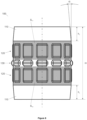
- the sleeve connector for tubular metal posts or simply, the sleeve connector (100), according to the invention, is a part intended for the mechanical joining of two tubular metal posts (300) and comprises, essentially, a total body height (H) provided with two centralization regions (110), two locking regions (120) and an abutment region (130).
- Each centralization region (110) is located at one of the open ends of the sleeve connector (100), while the two locking regions (120) are adjacent to the respective regions of centralization (110) and equidistant from a central abutment region (130).
- Each centralization region (110) is conical and presents a height (h c ) corresponding to 5 and 50%, preferably 15% of the locking region (120) external diameter (D) of the sleeve connector (100), while the inclination angle (a) of the cone is between 2 and 40°, depending, specially, on the application and measurements of the components involved.
- Each locking region (120) is provided with a plurality of locking protuberances (121), arranged in order to form a ring around the external perimeter of the locking region (120).
- Each locking protuberance (121) presents a length (ct) of 10 to 30%, preferably 20% of the external diameter (D), a width (It) of 6 to 20%, preferably 13% of the external diameter (D) and a height or radial distance (ht), measured from the external perimeter of the locking region (120), which corresponds to a value between 0.15 and 4%, preferably, between 1 and 2% of the locking region (120) external diameter (D).
- the abutment region (130) is provided with a plurality of abutment protuberances (131), arranged in order to form a ring around the external perimeter of the abutment region (130).
- Each abutment protuberance (131) presents a height or radial distance (h e ), measured from the external perimeter of the locking region (120), which corresponds to a value between 30 and 80%, preferably 60% of the wall thickness of the tubular metal post (300) involved.
- the structural arrangement according to the present invention surpasses the solutions in the state of the art, being an object of practical use, perfectly suitable for industrial application, presenting a new arrangement, involving non-obviousness and resulting in a functional improvement of use.
Landscapes
- Engineering & Computer Science (AREA)
- Structural Engineering (AREA)
- General Engineering & Computer Science (AREA)
- Life Sciences & Earth Sciences (AREA)
- General Life Sciences & Earth Sciences (AREA)
- Mining & Mineral Resources (AREA)
- Paleontology (AREA)
- Civil Engineering (AREA)
- Mechanical Engineering (AREA)
- Mutual Connection Of Rods And Tubes (AREA)
- Piles And Underground Anchors (AREA)
- Joining Of Building Structures In Genera (AREA)
Claims (11)
- Hülsenverbinder mit verschiedenen Querschnitten für Metallrohrpfosten, insbesondere ein Hülsenverbinder (100) zum Verbinden von Metallrohrpfosten (300), wobei der Hülsenverbinder zwei Zentralisierungsbereiche (110), zwei Verriegelungsbereiche (120) und einen Anlagebereich (130) umfasst, wobei die Verriegelungsbereiche (120) mit einem Ring aus Verriegelungsvorsprüngen (121) versehen sind, dadurch gekennzeichnet, dass deren Höhe (ht) 0,15 bis 4 % des Außendurchmessers (D) des Verriegelungsbereichs (120) entspricht,
wobei die Verriegelungsbereiche (120) mit dem Ring aus Verriegelungsvorsprüngen (121) versehen sind, die die genannte Höhe (ht) aufweisen, um das Zusammenverriegeln der Enden der Metallrohrpfosten (300) durch die mechanische Verformung der Verriegelungsvorsprünge (121) zu erleichtern. - Hülsenverbinder nach Anspruch 1, dadurch gekennzeichnet, dass sich jeder Zentralisierungsbereich (110) an einem der offenen Enden des Hülsenverbinders (100) befindet, während die beiden Verriegelungsbereiche (120) neben den jeweiligen Zentralisierungsbereichen (110) und äquidistant von einem zentralen Anlagebereich (130) liegen.
- Hülsenverbinder nach Anspruch 1, dadurch gekennzeichnet, dass jeder Zentralisierungsbereich (110) kegelförmig ist und eine Höhe (hc) aufweist, die 5 bis 50 %, vorzugsweise 15 % des Außendurchmessers (D) des Verriegelungsbereichs (120) des Hülsenverbinders (100) entspricht.
- Hülsenverbinder nach Anspruch 3, dadurch gekennzeichnet, dass der Neigungswinkel (α) des Kegels zwischen 2 und 40° beträgt.
- Hülsenverbinder nach Anspruch 1, dadurch gekennzeichnet, dass jeder Verriegelungsvorsprung (121) eine Länge (ct) von 10 bis 30 %, vorzugsweise 20 % des Außendurchmessers (D) beträgt.
- Hülsenverbinder nach Anspruch 5, dadurch gekennzeichnet, dass jeder Verriegelungsvorsprung (121) eine Breite (It) von 6 bis 20 %, vorzugsweise 13 % des Außendurchmessers (D) beträgt.
- Hülsenverbinder nach Anspruch 1, dadurch gekennzeichnet, dass jeder Verriegelungsbereich (120) einer Außenfläche (ST1, ST2) entspricht, wobei die Summe der Verriegelungsvorsprungsflächen (121) einem Wert zwischen 60 und 100 % der Summe der Außenflächen (ST1, ST2) entsprechen soll.
- Hülsenverbinder nach Anspruch 1, dadurch gekennzeichnet, dass der Anlagebereich (130) mit einer Vielzahl von Anlagevorsprüngen (131) versehen ist, die einen Ring um den Außenumfang des Anlagebereichs (130) bilden.
- Hülsenverbinder nach Anspruch 8, dadurch gekennzeichnet, dass jeder Anlagevorsprung (131) eine Höhe bzw. radiale Distanz (he) aufweist, die einem Wert zwischen 30 und 80 %, vorzugsweise 60 % der Wandstärke des betreffenden Metallrohrpfostens (300) entspricht.
- Hülsenverbinder nach Anspruch 1, dadurch gekennzeichnet, dass die Höhe (ht) der Verriegelungsvorsprünge (121) zwischen 1 und 2 % des Außendurchmessers (D) des Verriegelungsbereichs (120) entspricht.
- Verfahren zum Verbinden von Metallrohrpfosten (300) unter Verwendung eines Hülsenverbinders gemäß Anspruch 1, wobei die Enden der Metallrohrpfosten (300) miteinander verriegelt werden, wenn die Hülse (100) zwischen sie eingesetzt wird, und zwar durch mechanische Verformung der Verriegelungsvorsprünge (121).
Applications Claiming Priority (2)
| Application Number | Priority Date | Filing Date | Title |
|---|---|---|---|
| BR202017024392-9U BR202017024392Y1 (pt) | 2017-11-13 | 2017-11-13 | Disposição construtiva introduzida em luva de conexão de diversas seções para estacas tubulares metálicas |
| PCT/BR2018/050416 WO2019090409A1 (pt) | 2017-11-13 | 2018-11-12 | Disposição construtiva introduzida em luva de conexão de diversas seções para estacas tubulares metálicas |
Publications (4)
| Publication Number | Publication Date |
|---|---|
| EP3712332A1 EP3712332A1 (de) | 2020-09-23 |
| EP3712332A4 EP3712332A4 (de) | 2021-08-11 |
| EP3712332B1 true EP3712332B1 (de) | 2025-04-16 |
| EP3712332C0 EP3712332C0 (de) | 2025-04-16 |
Family
ID=66437434
Family Applications (1)
| Application Number | Title | Priority Date | Filing Date |
|---|---|---|---|
| EP18876354.4A Active EP3712332B1 (de) | 2017-11-13 | 2018-11-12 | Strukturanordnung, die in einen muffenverbinder mit verschiedenen querschnitten für rohrförmige metallpfosten eingebracht ist |
Country Status (5)
| Country | Link |
|---|---|
| US (1) | US11441287B2 (de) |
| EP (1) | EP3712332B1 (de) |
| CN (1) | CN213173701U (de) |
| BR (1) | BR202017024392Y1 (de) |
| WO (1) | WO2019090409A1 (de) |
Family Cites Families (18)
| Publication number | Priority date | Publication date | Assignee | Title |
|---|---|---|---|---|
| US1188485A (en) * | 1910-09-03 | 1916-06-27 | Underpinning & Foundation Company | Tube joint and guide. |
| US1051427A (en) * | 1912-01-18 | 1913-01-28 | Frank Mccluskey | Joint for tubular piling. |
| US1607725A (en) * | 1921-09-01 | 1926-11-23 | Davis Reuben | Coupling for steel piling |
| US2353561A (en) * | 1942-12-23 | 1944-07-11 | Macarthur Concrete Pile Corp | Coupling sleeve for tubular piling |
| GB974115A (en) * | 1961-12-15 | 1964-11-04 | Carr Fastener Co Ltd | Device for connecting tubes or tube-like elements to one another |
| DE7008903U (de) * | 1970-03-11 | 1970-09-10 | Staff & Schwarz Gmbh | Stativ, insbesondere fuer leuchten. |
| US3851980A (en) * | 1974-04-19 | 1974-12-03 | L Worth | Tubing connector |
| SE500185C2 (sv) * | 1992-01-21 | 1994-05-02 | Weland Ab | Anordning för sammankoppling av två rör |
| US20040131419A1 (en) * | 2003-01-03 | 2004-07-08 | Multiquip, Inc. | Articulating spline |
| CN202144590U (zh) | 2011-07-12 | 2012-02-15 | 中国建筑西南勘察设计研究院有限公司 | 一种变截面管桩接桩器 |
| CN202227334U (zh) * | 2011-10-09 | 2012-05-23 | 中建七局第三建筑有限公司 | 承插式钢管桩接头 |
| DE102012019105A1 (de) * | 2012-09-28 | 2014-04-03 | Carl Freudenberg Kg | Steckstück |
| CN203007935U (zh) * | 2012-12-14 | 2013-06-19 | 广东三和管桩有限公司 | 一种变截面混凝土桩接头 |
| CN204282351U (zh) * | 2014-12-09 | 2015-04-22 | 江西中泰来混凝土管桩有限公司 | 筒状管桩快速连接件 |
| CN105421448A (zh) | 2015-12-22 | 2016-03-23 | 钱俊 | 一种双壁波纹管预制管桩接桩结构及其工艺 |
| CN205875142U (zh) | 2016-08-08 | 2017-01-11 | 福建永强岩土股份有限公司 | 一种管桩快速连接接头 |
| CN207619977U (zh) * | 2017-08-26 | 2018-07-17 | 建华建材(嘉兴)有限公司 | 一种能够快速安装的混泥土管桩连接头 |
| US11448354B2 (en) * | 2019-07-30 | 2022-09-20 | Reinke Manufacturing Co., Inc. | Polymer-lined fluid transmission line |
-
2017
- 2017-11-13 BR BR202017024392-9U patent/BR202017024392Y1/pt active IP Right Grant
-
2018
- 2018-11-12 EP EP18876354.4A patent/EP3712332B1/de active Active
- 2018-11-12 US US16/763,887 patent/US11441287B2/en active Active
- 2018-11-12 CN CN201890001350.1U patent/CN213173701U/zh active Active
- 2018-11-12 WO PCT/BR2018/050416 patent/WO2019090409A1/pt not_active Ceased
Also Published As
| Publication number | Publication date |
|---|---|
| EP3712332A4 (de) | 2021-08-11 |
| EP3712332C0 (de) | 2025-04-16 |
| CN213173701U (zh) | 2021-05-11 |
| CA3082553A1 (en) | 2019-05-16 |
| US11441287B2 (en) | 2022-09-13 |
| US20200340200A1 (en) | 2020-10-29 |
| WO2019090409A1 (pt) | 2019-05-16 |
| BR202017024392Y1 (pt) | 2022-06-07 |
| BR202017024392U2 (pt) | 2019-06-04 |
| EP3712332A1 (de) | 2020-09-23 |
Similar Documents
| Publication | Publication Date | Title |
|---|---|---|
| TWI723246B (zh) | 用於機械及結構配管之機械聯結器 | |
| KR101039120B1 (ko) | 원터치식 철근 커플러 | |
| EP2840197A1 (de) | Gewindebewehrungsstabkupplung für deformierten bewehrungsstab und deformierter gewindebewehrungsstab | |
| AU612051B2 (en) | Composite bar structures of interlocked multiple members and method of producing the same | |
| KR20040063505A (ko) | 철근 연결구 | |
| KR101552321B1 (ko) | 철근 커플러 및 이를 이용한 철근 이음방법 | |
| CA3082553C (en) | Structural arrangement introduced into a sleeve connector having various cross-sections for tubular metal posts | |
| US6009914A (en) | Tube compression limiting apparatus and method | |
| EP3712332A1 (de) | Strukturanordnung, die in einen muffenverbinder mit verschiedenen querschnitten für rohrförmige metallpfosten eingebracht ist | |
| EP3270027B1 (de) | Rohrleitungsabschnitt mit zwei verbundenen vortriebsrohren | |
| JP4580355B2 (ja) | 合成セグメント | |
| KR102361603B1 (ko) | 회전 파일들을 결합하기 위한 단부판 시스템 | |
| KR101773434B1 (ko) | 콘크리트 파일과 강관 파일 결합용 이음장치 | |
| JP2009024436A (ja) | 鋼管杭の機械式継手 | |
| PL200251B1 (pl) | Kształtownik rurowy do zastosowania w układzie rusztowań, sposób wytwarzania kształtownika rurowego oraz rama rusztowania | |
| CN110863614B (zh) | 套索连接器及使用套索连接器连接钢筋的方法 | |
| JP4866894B2 (ja) | 定着部付き鉄筋、定着部付き鉄筋用素材、及び、アンカーボルト | |
| JP2002250478A (ja) | 連結構造 | |
| GB2557663A (en) | Ring lock system for a scaffolding system | |
| DE3910232C2 (de) | ||
| JP6578217B2 (ja) | 鉄筋連結装置 | |
| JPH0615044Y2 (ja) | 鋼管柱の接続構造 | |
| JP6173230B2 (ja) | 鋼管連結構造 | |
| EP1201939B1 (de) | Für aushärtbare Substanzen ausgebildetes Befestigungsmittel. | |
| JP2012127121A (ja) | 鉄筋の連結構造、及び連結方法 |
Legal Events
| Date | Code | Title | Description |
|---|---|---|---|
| STAA | Information on the status of an ep patent application or granted ep patent |
Free format text: STATUS: THE INTERNATIONAL PUBLICATION HAS BEEN MADE |
|
| PUAI | Public reference made under article 153(3) epc to a published international application that has entered the european phase |
Free format text: ORIGINAL CODE: 0009012 |
|
| STAA | Information on the status of an ep patent application or granted ep patent |
Free format text: STATUS: REQUEST FOR EXAMINATION WAS MADE |
|
| 17P | Request for examination filed |
Effective date: 20200609 |
|
| AK | Designated contracting states |
Kind code of ref document: A1 Designated state(s): AL AT BE BG CH CY CZ DE DK EE ES FI FR GB GR HR HU IE IS IT LI LT LU LV MC MK MT NL NO PL PT RO RS SE SI SK SM TR |
|
| AX | Request for extension of the european patent |
Extension state: BA ME |
|
| DAV | Request for validation of the european patent (deleted) | ||
| DAX | Request for extension of the european patent (deleted) | ||
| A4 | Supplementary search report drawn up and despatched |
Effective date: 20210709 |
|
| RIC1 | Information provided on ipc code assigned before grant |
Ipc: E02D 5/52 20060101AFI20210705BHEP Ipc: F16B 7/04 20060101ALI20210705BHEP |
|
| STAA | Information on the status of an ep patent application or granted ep patent |
Free format text: STATUS: EXAMINATION IS IN PROGRESS |
|
| 17Q | First examination report despatched |
Effective date: 20230525 |
|
| GRAP | Despatch of communication of intention to grant a patent |
Free format text: ORIGINAL CODE: EPIDOSNIGR1 |
|
| STAA | Information on the status of an ep patent application or granted ep patent |
Free format text: STATUS: GRANT OF PATENT IS INTENDED |
|
| INTG | Intention to grant announced |
Effective date: 20241118 |
|
| GRAS | Grant fee paid |
Free format text: ORIGINAL CODE: EPIDOSNIGR3 |
|
| GRAA | (expected) grant |
Free format text: ORIGINAL CODE: 0009210 |
|
| STAA | Information on the status of an ep patent application or granted ep patent |
Free format text: STATUS: THE PATENT HAS BEEN GRANTED |
|
| AK | Designated contracting states |
Kind code of ref document: B1 Designated state(s): AL AT BE BG CH CY CZ DE DK EE ES FI FR GB GR HR HU IE IS IT LI LT LU LV MC MK MT NL NO PL PT RO RS SE SI SK SM TR |
|
| REG | Reference to a national code |
Ref country code: GB Ref legal event code: FG4D |
|
| REG | Reference to a national code |
Ref country code: CH Ref legal event code: EP |
|
| REG | Reference to a national code |
Ref country code: IE Ref legal event code: FG4D |
|
| U01 | Request for unitary effect filed |
Effective date: 20250416 |
|
| U07 | Unitary effect registered |
Designated state(s): AT BE BG DE DK EE FI FR IT LT LU LV MT NL PT RO SE SI Effective date: 20250424 |
|
| PG25 | Lapsed in a contracting state [announced via postgrant information from national office to epo] |
Ref country code: ES Free format text: LAPSE BECAUSE OF FAILURE TO SUBMIT A TRANSLATION OF THE DESCRIPTION OR TO PAY THE FEE WITHIN THE PRESCRIBED TIME-LIMIT Effective date: 20250416 |
|
| PG25 | Lapsed in a contracting state [announced via postgrant information from national office to epo] |
Ref country code: NO Free format text: LAPSE BECAUSE OF FAILURE TO SUBMIT A TRANSLATION OF THE DESCRIPTION OR TO PAY THE FEE WITHIN THE PRESCRIBED TIME-LIMIT Effective date: 20250716 Ref country code: GR Free format text: LAPSE BECAUSE OF FAILURE TO SUBMIT A TRANSLATION OF THE DESCRIPTION OR TO PAY THE FEE WITHIN THE PRESCRIBED TIME-LIMIT Effective date: 20250717 |
|
| PG25 | Lapsed in a contracting state [announced via postgrant information from national office to epo] |
Ref country code: PL Free format text: LAPSE BECAUSE OF FAILURE TO SUBMIT A TRANSLATION OF THE DESCRIPTION OR TO PAY THE FEE WITHIN THE PRESCRIBED TIME-LIMIT Effective date: 20250416 |
|
| PG25 | Lapsed in a contracting state [announced via postgrant information from national office to epo] |
Ref country code: HR Free format text: LAPSE BECAUSE OF FAILURE TO SUBMIT A TRANSLATION OF THE DESCRIPTION OR TO PAY THE FEE WITHIN THE PRESCRIBED TIME-LIMIT Effective date: 20250416 |
|
| PG25 | Lapsed in a contracting state [announced via postgrant information from national office to epo] |
Ref country code: RS Free format text: LAPSE BECAUSE OF FAILURE TO SUBMIT A TRANSLATION OF THE DESCRIPTION OR TO PAY THE FEE WITHIN THE PRESCRIBED TIME-LIMIT Effective date: 20250716 |
|
| PG25 | Lapsed in a contracting state [announced via postgrant information from national office to epo] |
Ref country code: IS Free format text: LAPSE BECAUSE OF FAILURE TO SUBMIT A TRANSLATION OF THE DESCRIPTION OR TO PAY THE FEE WITHIN THE PRESCRIBED TIME-LIMIT Effective date: 20250816 |
|
| U20 | Renewal fee for the european patent with unitary effect paid |
Year of fee payment: 8 Effective date: 20251015 |
|
| PG25 | Lapsed in a contracting state [announced via postgrant information from national office to epo] |
Ref country code: SM Free format text: LAPSE BECAUSE OF FAILURE TO SUBMIT A TRANSLATION OF THE DESCRIPTION OR TO PAY THE FEE WITHIN THE PRESCRIBED TIME-LIMIT Effective date: 20250416 |
|
| PG25 | Lapsed in a contracting state [announced via postgrant information from national office to epo] |
Ref country code: CZ Free format text: LAPSE BECAUSE OF FAILURE TO SUBMIT A TRANSLATION OF THE DESCRIPTION OR TO PAY THE FEE WITHIN THE PRESCRIBED TIME-LIMIT Effective date: 20250416 |
|
| PG25 | Lapsed in a contracting state [announced via postgrant information from national office to epo] |
Ref country code: SK Free format text: LAPSE BECAUSE OF FAILURE TO SUBMIT A TRANSLATION OF THE DESCRIPTION OR TO PAY THE FEE WITHIN THE PRESCRIBED TIME-LIMIT Effective date: 20250416 |
|
| PLBE | No opposition filed within time limit |
Free format text: ORIGINAL CODE: 0009261 |
|
| STAA | Information on the status of an ep patent application or granted ep patent |
Free format text: STATUS: NO OPPOSITION FILED WITHIN TIME LIMIT |
|
| REG | Reference to a national code |
Ref country code: CH Ref legal event code: L10 Free format text: ST27 STATUS EVENT CODE: U-0-0-L10-L00 (AS PROVIDED BY THE NATIONAL OFFICE) Effective date: 20260225 |
|
| 26N | No opposition filed |
Effective date: 20260119 |