EP3712607A1 - Ultraschallwandler mit einer strukturierten ankoppelschicht - Google Patents
Ultraschallwandler mit einer strukturierten ankoppelschicht Download PDFInfo
- Publication number
- EP3712607A1 EP3712607A1 EP19164629.8A EP19164629A EP3712607A1 EP 3712607 A1 EP3712607 A1 EP 3712607A1 EP 19164629 A EP19164629 A EP 19164629A EP 3712607 A1 EP3712607 A1 EP 3712607A1
- Authority
- EP
- European Patent Office
- Prior art keywords
- coupling layer
- ultrasonic transducer
- piezo element
- structuring
- ultrasonic
- Prior art date
- Legal status (The legal status is an assumption and is not a legal conclusion. Google has not performed a legal analysis and makes no representation as to the accuracy of the status listed.)
- Granted
Links
Images


Classifications
-
- G—PHYSICS
- G01—MEASURING; TESTING
- G01N—INVESTIGATING OR ANALYSING MATERIALS BY DETERMINING THEIR CHEMICAL OR PHYSICAL PROPERTIES
- G01N29/00—Investigating or analysing materials by the use of ultrasonic, sonic or infrasonic waves; Visualisation of the interior of objects by transmitting ultrasonic or sonic waves through the object
- G01N29/22—Details, e.g. general constructional or apparatus details
- G01N29/24—Probes
- G01N29/2437—Piezoelectric probes
-
- B—PERFORMING OPERATIONS; TRANSPORTING
- B06—GENERATING OR TRANSMITTING MECHANICAL VIBRATIONS IN GENERAL
- B06B—METHODS OR APPARATUS FOR GENERATING OR TRANSMITTING MECHANICAL VIBRATIONS OF INFRASONIC, SONIC, OR ULTRASONIC FREQUENCY, e.g. FOR PERFORMING MECHANICAL WORK IN GENERAL
- B06B1/00—Methods or apparatus for generating mechanical vibrations of infrasonic, sonic, or ultrasonic frequency
- B06B1/02—Methods or apparatus for generating mechanical vibrations of infrasonic, sonic, or ultrasonic frequency making use of electrical energy
- B06B1/06—Methods or apparatus for generating mechanical vibrations of infrasonic, sonic, or ultrasonic frequency making use of electrical energy operating with piezoelectric effect or with electrostriction
- B06B1/0644—Methods or apparatus for generating mechanical vibrations of infrasonic, sonic, or ultrasonic frequency making use of electrical energy operating with piezoelectric effect or with electrostriction using a single piezoelectric element
- B06B1/0662—Methods or apparatus for generating mechanical vibrations of infrasonic, sonic, or ultrasonic frequency making use of electrical energy operating with piezoelectric effect or with electrostriction using a single piezoelectric element with an electrode on the sensitive surface
- B06B1/0681—Methods or apparatus for generating mechanical vibrations of infrasonic, sonic, or ultrasonic frequency making use of electrical energy operating with piezoelectric effect or with electrostriction using a single piezoelectric element with an electrode on the sensitive surface and a damping structure
-
- G—PHYSICS
- G01—MEASURING; TESTING
- G01N—INVESTIGATING OR ANALYSING MATERIALS BY DETERMINING THEIR CHEMICAL OR PHYSICAL PROPERTIES
- G01N29/00—Investigating or analysing materials by the use of ultrasonic, sonic or infrasonic waves; Visualisation of the interior of objects by transmitting ultrasonic or sonic waves through the object
- G01N29/22—Details, e.g. general constructional or apparatus details
- G01N29/24—Probes
- G01N29/2437—Piezoelectric probes
- G01N29/245—Ceramic probes, e.g. lead zirconate titanate [PZT] probes
-
- G—PHYSICS
- G01—MEASURING; TESTING
- G01N—INVESTIGATING OR ANALYSING MATERIALS BY DETERMINING THEIR CHEMICAL OR PHYSICAL PROPERTIES
- G01N29/00—Investigating or analysing materials by the use of ultrasonic, sonic or infrasonic waves; Visualisation of the interior of objects by transmitting ultrasonic or sonic waves through the object
- G01N29/22—Details, e.g. general constructional or apparatus details
- G01N29/28—Details, e.g. general constructional or apparatus details providing acoustic coupling, e.g. water
-
- G—PHYSICS
- G10—MUSICAL INSTRUMENTS; ACOUSTICS
- G10K—SOUND-PRODUCING DEVICES; METHODS OR DEVICES FOR PROTECTING AGAINST, OR FOR DAMPING, NOISE OR OTHER ACOUSTIC WAVES IN GENERAL; ACOUSTICS NOT OTHERWISE PROVIDED FOR
- G10K11/00—Methods or devices for transmitting, conducting or directing sound in general; Methods or devices for protecting against, or for damping, noise or other acoustic waves in general
- G10K11/002—Devices for damping, suppressing, obstructing or conducting sound in acoustic devices
-
- G—PHYSICS
- G10—MUSICAL INSTRUMENTS; ACOUSTICS
- G10K—SOUND-PRODUCING DEVICES; METHODS OR DEVICES FOR PROTECTING AGAINST, OR FOR DAMPING, NOISE OR OTHER ACOUSTIC WAVES IN GENERAL; ACOUSTICS NOT OTHERWISE PROVIDED FOR
- G10K11/00—Methods or devices for transmitting, conducting or directing sound in general; Methods or devices for protecting against, or for damping, noise or other acoustic waves in general
- G10K11/02—Mechanical acoustic impedances; Impedance matching, e.g. by horns; Acoustic resonators
Definitions
- the invention relates to an ultrasonic transducer having a piezo element and a coupling layer.
- the coupling layer is attached to the sound-emitting side of the piezo element and has a structure which is formed by cutouts.
- the invention also relates to a method for reducing secondary vibrations of the ultrasonic signal of the ultrasonic transducer according to the invention and the use of the method according to the invention in non-destructive, in particular contactless, material testing.
- Ultrasound is regularly used in materials testing. Air ultrasound is a special test method in which air is used as the coupling medium. The ultrasonic transducer is not in contact with the test material, which enables non-contact, non-destructive testing of components or materials.
- a challenge in air-borne ultrasound testing is the use of air as a coupling medium, since the emission of ultrasound in air is characterized by poor acoustic coupling.
- the acoustic adaptation describes the different impedance between the solid transducer medium and the propagation medium air.
- ⁇ / 4 coupling layers In order to improve the poor acoustic adaptation to the medium of air, the use of ⁇ / 4 coupling layers is known from the prior art. These resemble the Impedance difference between the transducer medium and air and thus improve the acoustic coupling of the ultrasonic signal.
- the coupling layer is firmly connected to the surface of the piezo element and is characterized by a surface parallel to the surface of the piezo element.
- the transverse vibrations lead to the formation of undesired secondary vibrations in the ultrasonic signal.
- the secondary vibrations caused by the transverse vibrations lengthen the ultrasonic pulse that is emitted by the ultrasonic transducer and thereby reduce the realtive bandwidth of the ultrasonic signal.
- a broadband ultrasonic signal is desirable or even necessary for use in materials testing.
- air ultrasound is used to test composite bonds.
- defects such as air inclusions, delamination, adhesive defects, contamination, channels, cracks and / or kissing bonds can occur here. Due to the large number of errors that occur, the requirements for the measurement task are very diverse. Due to the different lateral and axial extent of the errors as well as different damping behavior, it is necessary to measure as broadly as possible.
- Current air-ultrasonic probes are designed to be narrow-band, as already described above. Relative bandwidths as implemented in immersion technology or contact technology measurement cannot currently be used in the field of air-ultrasonic testing.
- the WO 94/05004 discloses an ultrasonic transducer that has been optimized for acoustic adaptation to the air as a medium.
- a ⁇ / 4 coupling layer is used for this, which has incisions on its rear side, these incisions preferably being concentric, annular grooves which have a maximum penetration depth of a quarter of the coupling layer.
- Subject of WO 94/05004 it is not to suppress transverse vibrations of the piezo element in order to reduce disturbing secondary vibrations in the ultrasonic signal, but only to make an acoustic adaptation to the surrounding medium air.
- the patent application FR 2 546 306 A1 also discloses an ultrasonic transducer which has been optimized with regard to the acoustic adaptation to the medium of air.
- cutouts were made in the coupling layer which are equidistant from one another and form, for example, rectangular, diamond-shaped or square sections. In any case, the recesses form mutually symmetrical sections. This symmetry is central to the way the in the FR 2 546 306 A1 described Ultrasonic transducer.
- cutouts which form elements and / or regions which are asymmetrical to one another in the sense of the present invention are particularly suitable for suppressing the transverse vibrations of the piezo element.
- the teaching of FR 2 546 306 A1 can therefore also not serve to achieve the object of the present invention.
- the object of the invention is to overcome the disadvantages of the prior art and to provide an ultrasonic transducer which is specially adapted to air-ultrasonic testing and has a high relative bandwidth. Due to the high relative bandwidth, the ultrasonic transducer according to the invention is suitable for a wide range of applications in materials testing.
- the object of the invention is achieved by an ultrasonic transducer which has a damping element, a piezo element and a coupling layer.
- the coupling layer is attached to the sound-emitting side of the piezo element and has a structure.
- the structuring is formed by one or more cutouts in the coupling layer, at least one cutout that forms a structuring running continuously through the surface of the coupling layer.
- the structuring can be introduced on the front side and / or on the rear side of the coupling layer, the structuring having a predefined penetration depth into the coupling layer and / or completely severing the coupling layer.
- the coupling layer is divided into several areas and / or elements by the structuring, the areas and / or elements of the coupling layer which are formed by the structuring preferably not having any symmetry with respect to one another.
- the invention also relates to a method for reducing secondary vibrations of the ultrasonic signal of the ultrasonic transducer according to the invention.
- the thickness oscillation of the piezo element is stimulated by a burst signal and the structuring of the coupling layer prevents post oscillations of the piezo element in the form of transverse oscillations, whereby secondary oscillations of the ultrasonic signal are reduced.
- the invention further relates to the use of the ultrasonic transducer and / or the method in non-destructive, in particular contactless, material testing.
- the ultrasonic transducer according to the invention has a damping element, a piezo element and a coupling layer.
- a coupling layer is applied to the sound-emitting side of the piezo element.
- the coupling layer is used for acoustic adaptation to the medium of air and is preferably designed as a ⁇ / 4 layer or as a multiple of a ⁇ / 4 layer.
- the coupling layer is a ⁇ / 4 layer or a multiple thereof.
- the coupling layer is attached to the sound-emitting side of the piezo element, the surface of the coupling layer that is connected to the piezo element being referred to below as the rear of the coupling layer and the surface of the coupling layer that is in contact with the surrounding medium (air) , hereinafter referred to as the front side of the coupling layer.
- the coupling layer also has a structuring, the structuring being formed by one or more cutouts in the coupling layer.
- the recesses in the coupling layer are designed so that the front side of the coupling layer runs parallel to the surface of the piezo element. This measure ensures an optimal acoustic coupling to the surrounding medium of air.
- the coupling layer according to the invention has at least one recess which runs continuously through the surface of the coupling layer. This means that this at least one cutout begins and ends at an edge of the coupling layer, this at least one cutout being continuous, that is to say without interruption.
- a plurality of cutouts in the coupling layer which form the structuring, can also be formed continuously through the surface of the coupling layer.
- all of the cutouts in the coupling layer run continuously through the surface of the coupling layer.
- precisely one cutout runs continuously through the coupling layer and all further cutouts that also form the structure do not run continuously through the surface of the coupling layer.
- transverse vibrations of the piezo element cause disruptive secondary vibrations, which undesirably lengthen the ultrasonic pulse of the ultrasonic transducer and thus reduce the relative bandwidth.
- a coupling layer which has at least one continuous cutout is particularly well suited for suppressing transverse vibrations of the piezo element. This reduces the amplitude of undesired secondary vibrations, which means that the length of the emitted ultrasonic pulse can be shortened and its relative bandwidth is thus greater.
- the cutouts in the coupling layer can only be formed on the front side of the coupling layer or only on the rear side of the coupling layer. According to the invention, it is also possible that both the front and the rear of the coupling layer have cutouts.
- the recesses that are made on the front and / or back of the coupling layer can have a predefined penetration depth and / or completely sever the coupling layer.
- the coupling layer is severed when a cutout begins on the front side and is formed up to the rear side of the coupling layer or begins on the rear side and is correspondingly formed up to the front side of the coupling layer. If a recess has a predefined penetration depth, this is preferably constant for the respective recess.
- the penetration depth for a recess is not constant but varies.
- all of the cutouts have a predefined penetration depth and none of the cutouts sever the coupling layer. In another embodiment, all of the cutouts cut through the coupling layer completely. In a further embodiment of the invention, the coupling layer has cutouts with a defined penetration depth and cutouts which completely cut through the coupling layer.
- the ultrasonic transducer according to the invention has several recesses of a predefined penetration depth, then according to the invention these can extend to different depths into the coupling layer. This means that the individual recesses can have different penetration depths.
- the ultrasonic transducer therefore has a plurality of cutouts in the structure on the front and / or back of the coupling layer, which cutouts extend into the coupling layer at different depths.
- the coupling layer is divided into several areas and / or elements by the structuring. In this case, one or more areas are formed in the coupling layer between the cutouts or between the cutout and the edge of the coupling layer if the cutout or the cutouts have a certain penetration depth. If, on the other hand, the cutouts cut through the coupling layer completely, individual elements of the coupling layer are created.
- the areas and / or elements of the coupling layer that are formed by the structuring preferably do not have any symmetry with respect to one another.
- the areas and / or elements of the coupling layer that are formed by the structuring do not have any symmetry with respect to one another.
- the ultrasonic transducer according to the invention is therefore advantageously able to transmit an ultrasonic pulse with side echoes that are significantly reduced in amplitude, which in turn shortens the ultrasonic pulse overall and thus a larger relative bandwidth is available.
- the recesses that form the structuring can have different shapes.
- the recesses can be linear.
- the recesses in the coupling layer run linearly when the surface of the coupling layer on which the structure is located is viewed from above.
- the structuring of the coupling layer is formed by one or more linear cutouts.
- the structuring is formed by one or more curved cutouts.
- the recesses in the coupling layer are curved when the surface of the coupling layer on which the structure is located is viewed from above.
- the coupling layer has several cutouts with different shapes.
- the structuring of the coupling layer can be formed in one embodiment by a combination of linear and curved recesses.
- All recesses that form the structuring of the coupling layer run perpendicular to the surface of the piezo element. That is to say, the elements and / or areas of the coupling layer which are formed by the structuring are perpendicular to the surface of the piezo element. This configuration ensures an efficient acoustic adaptation to the medium air by the coupling layer according to the invention.
- the recesses in the coupling layer are filled with air.
- the recesses in the coupling layer are filled with a filler material such as a plastic or a resin.
- a filler material such as a plastic or a resin.
- Suitable plastics are plastics selected from the group comprising NBR (copolymer of butadiene and acrylonitrile), silicone, PUR (polyurethane).
- Suitable resins are resins selected from the group of epoxy resins. In a particularly preferred embodiment of the invention, NBR is used as the filler material.
- the coupling layer has an acoustic impedance that is the geometric mean of the acoustic impedance of the transducer medium and the acoustic impedance of air. Since there is practically no such material, a material is used for the coupling layer that has the lowest possible density and can still be mechanically processed.
- the coupling layer therefore preferably has a material with a density less than 1 g / cm 3 , particularly preferably less than 0.4 g / cm 3 .
- the coupling layer has a material from the group comprising foams, particularly preferably syntactic foams.
- Syntactic foams are composite materials in which hollow microspheres made of glass or ceramic are enclosed in a foam made, for example, of polyethylene or epoxy resin.
- the coupling layer is preferably glued to the surface of the piezo element.
- the bonding can be carried out selectively, partially over the entire surface or over the entire surface. Gluing the coupling layer to the surface of the piezoelectric element over the entire surface is preferred.
- Suitable adhesives are selected from the group comprising epoxy resin, PUR (polyurethane), cyanoacrylates and structural adhesives, bonding with epoxy resin being particularly preferred.
- a piezo composite or a piezo ceramic can be used as the piezo element.
- the piezo element has a piezoceramic selected from the group comprising PZT (lead zirconate titanate), PMN (lead metaniobate) and BTO (barium titanate).
- the piezo element has a piezo composite, preferably a 1-3 piezo composite. These are parallel, vertical rods made of a PZT (lead zirconate titanate) material, which are surrounded by a matrix made of epoxy resin.
- PZT lead zirconate titanate
- the ultrasonic transducer according to the invention has a damping element.
- the piezo element is embedded in the damping element on its rear side and on the sides, the sound-emitting side of the piezo element on which the coupling layer is located remains free.
- the damping element it is possible to avoid the emission of ultrasound in an undesired direction, or to control the emission direction in a targeted manner.
- the damping element is formed, for example, from a solid body or a potting compound. Suitable casting compounds consist, for example, of plastics such as polyurethanes (PUR) or of silicone.
- the present invention also includes a method for reducing the amplitude of secondary vibrations of the ultrasonic signal of an ultrasonic transducer according to the invention.
- the thickness oscillation of the piezo element of the ultrasonic transducer according to the invention is excited by a burst signal, a burst signal consisting of 1-20 oscillations with a frequency of 50 kHz to 1 MHz.
- transverse oscillations of the piezo element In addition to the thickness oscillation, transverse oscillations of the piezo element also develop. These transverse vibrations are prevented by the coupling layer of the ultrasonic transducer according to the invention, as a result of which the amplitudes of secondary vibrations in the ultrasonic pulse generated are significantly reduced. This leads to the generation of an ultrasonic pulse with a shorter pulse duration compared to ultrasonic pulses that are generated with ultrasonic transducers from the prior art. A shorter pulse duration is synonymous with a larger relative bandwidth of the ultrasonic signal.
- an ultrasonic transducer according to the invention which has a typical transducer frequency of 230 kHz, a pulse duration between 50 and 60 microseconds can be achieved; the relative bandwidth is then 40%.
- Comparable ultrasonic transducers from the prior art have a pulse duration of 200 ⁇ s and a relative bandwidth of 10%.
- the ultrasonic transducer according to the invention enables significantly shorter pulse durations and thus also a significantly increased relative bandwidth of the ultrasonic pulse generated.
- an ultrasound pulse is generated in the method according to the invention which has a relative bandwidth between 10% and 40%, preferably between 20% and 40%, particularly preferably between 30% and 40%.
- the invention further comprises the use of the ultrasonic transducer according to the invention and / or the method according to the invention in non-destructive material testing.
- the ultrasonic transducer according to the invention due to the air ultrasound, it is possible to carry out the material test with the ultrasonic transducer according to the invention and / or the method according to the invention without contact.
- the ultrasonic transducer according to the invention and / or the method according to the invention are used in materials testing in order to test composite bonds.
- a large number of errors can be detected here by the method according to the invention. These are, for example, air pockets, delaminations, adhesive defects, contamination, channels, cracks and / or kissing bonds. Due to the different lateral and axial extent of the errors as well as different damping behavior, it is necessary to measure as broadly as possible.
- the use of air-ultrasonic testing in materials testing is only possible because the method according to the invention provides an ultrasonic pulse that is broad enough to meet the above-mentioned measurement task. Ultrasonic pulses that are generated with state-of-the-art air ultrasound heads are not suitable for these measuring tasks due to their lower relative bandwidth.
- the ultrasonic transducer 10 according to the invention is shown in different versions.
- the ultrasonic transducer has a damping element 15, a piezo element 11, an adhesive layer 12 and a coupling layer 13 .
- a recess 14 is made on the back of the coupling layer 13
- Figure 1b represents a coupling layer 13 with three cutouts 14 on the back of the coupling layer 13 .
- the three recesses 14 each extend into the coupling layer 13 at different depths. It would also be possible for all three recesses 14 to have the same penetration depth.
- Figure 1c shows an ultrasonic transducer 10 with a coupling layer 13, which has three cutouts 14 on the front side, the three cutouts 14 reaching different depths into the coupling layer 13 .
- all recesses 14 it would also be possible according to the invention for all recesses 14 to have the same penetration depth.
- Figure 1e shows an ultrasonic transducer 10 with three cutouts 14 which completely cut through the coupling layer. The coupling layer 13 is divided into individual elements by the cutouts 14 .
- the structuring can also be formed by a combination of cutouts 14 on the front and on the rear of the coupling layer 13 , which Reach different depths into the coupling layer 13 , as well as through recesses 14 which completely cut through the coupling layer 13 .
- Such an implementation is in Figure 1f ) shown.
- the coupling layer 13 has two cutouts 14 on the rear and one cutout 14 on the front, as well as a cutout 14 which completely cuts through the coupling layer 13 .
- Figure 2a ) - d) shows the top view of a coupling layer 13, the course of the recesses 14 can be seen through which the structuring is formed.
- Figure 2a shows a coupling layer 13 with two linearly extending cutouts 14. In the figure, the two cutouts 14 intersect ; this is not absolutely necessary according to the invention.
- Figure 2b shows a coupling layer 13, the recesses 14 of which are all curved, with all of the recesses beginning and ending at the edge of the coupling layer 13 .
- the coupling layer 13 has a combination of curved recesses 14 and linear recesses 14 Figure 2c ) on.
- Figure 2d represents a coupling layer 13 in which the structuring is formed from a multiplicity of cutouts 14 .
- the recesses 14 are partially linear and partially curved.
- a linear recess begins and ends at the edge of the coupling layer 13, while the other recesses 14, which also belong to the structuring, begin at the edge of the coupling layer 13 but are not continuous, but end in the middle of the coupling layer 13 .
- the ones in the Figures 2a) to 2d ) Structures shown can be applied both on the front side and on the rear side of the coupling layer 13 .
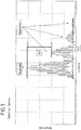
- FIG 3 shows an ultrasonic pulse that was generated with a conventional ultrasonic transducer.
- the conventional ultrasonic transducer known from the prior art consists of a piezo element on which a ⁇ / 4 layer was applied as a coupling layer. Both surfaces, that is to say the front and back of the coupling layer, do not have any structuring but show a planar course.
- the ultrasonic transducer is excited to vibrate through the thickness with a burst signal.
- the emitted ultrasonic pulse is recorded and the amplitude of the emitted ultrasonic pulse is determined as a function of the transit time in Figure 3 shown.
- the ultrasonic pulse has, in addition to a main echo, three easily recognizable side echoes, which are formed by secondary vibrations.
- the side echoes are caused by the Caused transverse vibrations of the piezo element.
- the side echoes contribute to the pulse width of the ultrasonic pulse of ⁇ L1.
- the difference between the amplitude of the main echo and the amplitude of the first secondary echo is ⁇ A1. It can be clearly seen that the side echoes significantly lengthen the pulse width of the ultrasonic pulse.
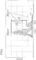
- Figure 4 shows the amplitude of an ultrasonic pulse as a function of the transit time, which was generated with an ultrasonic transducer according to the invention.
- the amplitude of the main echo is compared to the ultrasonic pulse that is generated with a conventional ultrasonic transducer (see Figure 3 ), unchanged. It can be clearly seen that the amplitude of the side echoes, which are formed by side vibrations, is greatly reduced compared to the ultrasonic pulse of a conventional ultrasonic transducer.
- ⁇ A2 is significantly larger than ⁇ A1.
- the following side echoes are also characterized by a lower amplitude.
- the ultrasonic pulse of the ultrasonic transducer according to the invention advantageously has only two side echoes, while the ultrasonic pulse of a conventional ultrasonic transducer has three side echoes ( Figure 3 ). The third side echo is completely attenuated.
- the pulse width of the ultrasonic pulse ⁇ L2 of the ultrasonic transducer according to the invention is significantly smaller than the pulse width of the ultrasonic pulse ⁇ L1 which was generated with a conventional ultrasonic transducer.
- the ultrasonic transducer according to the invention thus also has a larger relative bandwidth compared to the conventional ultrasonic transducer.
- An ultrasonic transducer is excited to vibrate thickly with a burst signal consisting of 5 vibrations at a frequency of 230 kHz.
- a coupling layer is applied to the piezo element, which is provided with linear cutouts on the front side, with all cutouts extending to the center of the coupling layer and being filled with air.
- the ultrasonic pulse emitted by the ultrasonic transducer has a pulse duration of approx. 100 ⁇ s and has a relative bandwidth of approx. 20%.
- An ultrasonic transducer is excited to vibrate thickly with a burst signal consisting of 5 vibrations at a frequency of 230 kHz.
- a coupling layer is applied to the piezo element, which is provided with linear recesses on the rear side, with all the recesses reaching different depths into the coupling layer and being filled with air.
- the ultrasonic pulse emitted by the ultrasonic transducer has a pulse duration of approx. 100 ⁇ s and has a relative bandwidth of approx. 20%.
- An ultrasonic transducer is excited to vibrate thickly with a burst signal consisting of 5 vibrations at a frequency of 230 kHz.
- a coupling layer is applied to the piezo element, the coupling layer having a structure that is formed by recesses that completely cut through the coupling layer and are filled with air.
- the ultrasonic pulse emitted by the ultrasonic transducer has a pulse duration of approx .30% up.
- An ultrasonic transducer is excited to vibrate thickly with a burst signal consisting of 5 vibrations at a frequency of 230 kHz.
- a coupling layer is applied to the piezo element, which is provided with linear recesses on the front, with all recesses extending to the middle of the coupling layer and being filled with NBR (copolymer of butadiene and acrylonitrile).
- the ultrasonic pulse emitted by the ultrasonic transducer has a pulse duration of around 50 ⁇ s and has a relative bandwidth of around 40%.
Landscapes
- Physics & Mathematics (AREA)
- Engineering & Computer Science (AREA)
- Chemical & Material Sciences (AREA)
- Biochemistry (AREA)
- General Physics & Mathematics (AREA)
- Health & Medical Sciences (AREA)
- Life Sciences & Earth Sciences (AREA)
- Analytical Chemistry (AREA)
- Pathology (AREA)
- General Health & Medical Sciences (AREA)
- Immunology (AREA)
- Acoustics & Sound (AREA)
- Multimedia (AREA)
- Ceramic Engineering (AREA)
- Mechanical Engineering (AREA)
- Investigating Or Analyzing Materials By The Use Of Ultrasonic Waves (AREA)
- Transducers For Ultrasonic Waves (AREA)
Abstract
Description
- Die Erfindung betrifft einen Ultraschallwandler aufweisend ein Piezoelement und eine Ankoppelschicht. Die Ankoppelschicht ist auf der schallabgebenden Seite des Piezoelementes angebracht und weist eine Strukturierung auf, welche durch Aussparungen gebildet wird. Die Erfindung betrifft weiterhin ein Verfahren zur Reduzierung von Nebenschwingungen des Ultraschallsignals des erfindungsgemäßen Ultraschallwandlers sowie die Verwendung des erfindungsgemäßen Verfahrens in der zerstörungsfreien, insbesondere kontaktlosen Materialprüfung.
- Ultraschall wird regelmäßig in der Materialprüfung eingesetzt. Luftultraschall stellt dabei ein spezielles Prüfverfahren dar, bei dem als Koppelmedium Luft verwendet wird. Der Ultraschallwandler ist dabei nicht in Kontakt mit dem Prüfmaterial, wodurch eine berührungslose, zerstörungsfreie Prüfung von Bauteilen oder Werkstoffen möglich ist.
- Eine Herausforderung in der Luftultraschallprüfung ist die Verwendung von Luft als Koppelmedium, da sich die Abstrahlung von Ultraschall in Luft durch eine schlechte akustische Ankopplung auszeichnet. Die akustische Anpassung beschreibt die unterschiedliche Impedanz zwischen dem festen Wandlermedium und dem Ausbreitungsmedium Luft.
- Klassische Luftultraschallwandler arbeiten meist im Radialresonanzbetrieb, das heißt, es wird die Radialschwingung des Piezoelementes ausgenutzt. Diese Ultraschallwandler zeichnen sich vor allem durch ein schmalbandiges Signal aus, wobei die Arbeitsfrequenz des Ultraschallwandlers direkt vom Radius des Piezoelementes abhängt. Durch die unterschiedliche Impedanz von Wandlermedium und Luft entsteht ein charakteristisches Ultraschallsignal, das sich durch verschiedene Schwingungsmoden auszeichnet. Aufgrund der schlechten Bedämpfbarkeit der Radialschwingungen von Piezoelementen, gibt es derzeit kein Verfahren mit dem die relative Bandbreite eines solchen Ultraschallwandlers signifikant erhöht werden kann.
- Um die schlechte akustische Anpassung an das Medium Luft zu verbessern, ist aus dem Stand der Technik die Verwendung von λ/4-Ankoppelschichten bekannt. Diese gleichen den Impedanzunterschied zwischen Wandlermedium und Luft an und verbessern damit die akustische Ankopplung des Ultraschallsignals. Die Ankopplungsschicht wird fest mit der Oberfläche des Piezoelementes verbunden und zeichnet sich durch eine zur Oberfläche des Piezoelementes parallele Oberfläche aus.
- Neben der Radialschwingung ist es auch möglich Ultraschall auf Grundlage der Dickenschwingung eines Piezoelementes zu erzeugen, dabei kommt es jedoch auch zur Ausbildung von Querschwingungen. Durch die starre Verbindung des Piezoelementes und der λ/4-Ankoppelschicht führen die Querschwingungen zur Ausbildung von unerwünschten Nebenschwingungen im Ultraschallsignal. Die durch die Querschwingungen verursachten Nebenschwingungen verlängern den Ultraschallpuls der vom Ultraschallwandler abgegeben wird und verringern dadurch die realtive Bandbreite des Ultraschallsignals.
- Für die Anwendung in der Materialprüfung ist jedoch in vielen Fällen ein breitbandiges Ultraschallsignal wünschenswert oder gar notwendig. Beispielsweise wird Luftultraschall in der Prüfung von Kompositverklebungen eingesetzt. Hier können eine Vielzahl unterschiedlicher Fehler, wie beispielsweise Lufteinschlüsse, Delaminationen, Klebefehler, Verunreinigungen, Kanäle, Risse und/oder Kissing Bonds auftreten. Durch die große Vielzahl an auftretenden Fehlern sind die Anforderungen an die Messaufgabe sehr vielfältig. Aufgrund der unterschiedlichen lateralen und axialen Ausdehnung der Fehler sowie unterschiedlichem Dämpfungsverhalten ist es notwendig, so breitbandig wie nur möglich zu messen. Aktuelle Luftultraschallprüfköpfe sind wie eingangs bereits beschrieben schmalbandig ausgeführt. Relative Bandbreiten, wie sie in der Tauchtechnik oder Kontakttechnikmessung umgesetzt werden, sind im Bereich der Luftultraschallprüfung aktuell nicht einsetzbar. Während bei Kontakt- bzw. Tauchtechnikmessungen relative Bandbreiten von 80-100% gängig sind, wird in der Luftultraschallprüfung derzeit mit relativen Bandbreiten von ca. 10% gearbeitet. Die relative Bandbreite Δf rel ergibt sich aus dem Verhältnis der Differenz der oberen Grenzfrequenz f u und der unteren Grenzfrequenz fl zur Mittenfrequenz f 0 des Ultraschallpulses und wird wie folgt berechnet:

- Um die beschriebenen Fehler sicher erfassen zu können, reichen die momentan im Luftultraschall erreichbaren relativen Bandbreiten jedoch nicht aus. Um die Vielzahl der möglichen Fehler detektieren zu können, ist es notwendig, die Probe bzw. den Prüfling mit mehreren Frequenzen zu untersuchen. Der dadurch entstehende Mehraufwand ist erheblich und führt oftmals zum Verwerfen des Prüfverfahrens.
- Anwender müssen dann die mit Tauch- und Kontakttechnik verbundenen Nachteile der Kontamination des Prüflings mit Koppelmittel in Kauf nehmen oder verzichten auf die aufwendige Flächenprüfung mit Ultraschall.
- Aus dem Stand der Technik sind zwar bereits Ultraschallwandler bekannt, die Aussparungen in der Ankoppelschicht aufweisen, jedoch mit dem Ziel eine möglichst optimale akustische Anpassung an das Medium Luft zu erreichen. Deren Lehren können daher aus den im Folgenden aufgeführten Gründen nicht für die Lösung der Aufgabe der vorliegenden Erfindung dienen.
- Die
WO 94/05004 WO 94/05004 WO 94/05004 - Die Patentanmeldung
FR 2 546 306 A1 FR 2 546 306 A1 FR 2 546 306 A1 - Die Aufgabe der Erfindung besteht darin, die Nachteile des Standes der Technik zu überwinden und einen Ultraschallwandler zur Verfügung zu stellen, der speziell an die Luftultraschallprüfung angepasst ist und eine hohe relative Bandbreite aufweist. Aufgrund der hohen relativen Bandbreite ist der erfindungsgemäße Ultraschallwandler für vielfältige Anwendungen in der Materialprüfung geeignet.
- Die Aufgabe der Erfindung wird gelöst durch einen Ultraschallwandler, der ein Dämpfungselement, ein Piezoelement und eine Ankoppelschicht aufweist. Die Ankoppelschicht ist auf der schallabgebenden Seite des Piezoelementes angebracht und weist eine Strukturierung auf. Die Strukturierung wird durch ein oder mehrere Aussparungen in der Ankoppelschicht ausgebildet, wobei mindestens eine Aussparung, die eine Strukturierung bildet, durchgängig durch die Oberfläche der Ankoppelschicht verläuft. Die Strukturierung kann erfindungsgemäß auf der Vorderseite und/oder auf der Rückseite der Ankoppelschicht eingebracht sein, wobei die Strukturierung eine vordefinierte Eindringtiefe in die Ankoppelschicht aufweist und/oder die Ankoppelschicht vollständig durchtrennt. Die Ankoppelschicht wird durch die Strukturierung in mehrere Bereiche und/oder Elemente geteilt, wobei die Bereiche und/oder Elemente der Ankoppelschicht, die durch die Strukturierung gebildet werden, vorzugsweise keine Symmetrie zueinander aufweisen.
- Die Erfindung betrifft weiterhin ein Verfahren zur Reduzierung von Nebenschwingungen des Ultraschallsignals des erfindungsgemäßen Ultraschallwandlers. Dabei wird die Dickenschwingung des Piezoelementes verfahrensgemäß durch ein Burstsignal angeregt und die Strukturierung der Ankoppelschicht verhindert Nachschwingungen des Piezoelementes in Form von Querschwingungen wodurch Nebenschwingungen des Ultraschallsignals reduziert werden.
- Weiterhin betrifft die Erfindung die Verwendung des Ultraschallwandlers und/oder des Verfahrens in der zerstörungsfreien, insbesondere kontaktlosen Materialprüfung.
- Der erfindungsgemäße Ultraschallwandler weist, ein Dämpfungselement, ein Piezoelement und eine Ankoppelschicht auf. Erfindungsgemäß wird auf der schallabgebenden Seite des Piezoelementes eine Ankoppelschicht angebracht. Die Ankoppelschicht dient der akustischen Anpassung an das Medium Luft und wird bevorzugt als λ/4-Schicht oder als ein Vielfaches einer λ/4-Schicht ausgeführt. Dabei ist λ die Wellenlänge der Dickenschwingung des Piezoelementes und die Dicke d der Ankoppelschicht beträgt

- In einer Ausführungsform der Erfindung ist die Ankoppelschicht eine λ/4-Schicht oder ein Vielfaches davon.
- Die Ankoppelschicht ist auf der schallabgebenden Seite des Piezoelementes angebracht, wobei die Oberfläche der Ankoppelschicht, die mit dem Piezoelement verbunden ist, im Folgenden als die Rückseite der Ankoppelschicht bezeichnet wird und die Oberfläche der Ankoppelschicht, die mit dem umgebenden Medium (Luft) in Berührung steht, im Folgenden als Vorderseite der Ankoppelschicht bezeichnet wird. Die Ankoppelschicht weist des Weiteren eine Strukturierung auf, wobei die Strukturierung durch ein oder mehrere Aussparungen in der Ankoppelschicht ausgebildet wird.
- Die Aussparungen in der Ankoppelschicht sind so ausgeführt, dass die Vorderseite der Ankoppelschicht parallel zur Oberfläche des Piezoelementes verläuft. Durch diese Maßnahme wird eine optimale akustische Ankopplung zum umgebenden Medium Luft gewährleistet.
- Die erfindungsgemäße Ankoppelschicht weist mindestens eine Aussparung auf, die durchgängig durch die Oberfläche der Ankoppelschicht verläuft. Das bedeutet, dass diese mindestens eine Aussparung an einem Rand der Ankoppelschicht beginnt und endet, wobei diese mindestens eine Aussparung durchgängig, das heißt ohne Unterbrechung, ausgebildet ist.
- Erfindungsgemäß können auch mehrere Aussparungen in der Ankoppelschicht, die die Strukturierung bilden, durchgängig durch die Oberfläche der Ankoppelschicht ausgebildet sein. In einer bevorzugten Ausführungsform der Erfindung verlaufen alle Aussparungen in der Ankoppelschicht durchgängig durch die Oberfläche der Ankoppelschicht.
- In einer weiteren Ausführungsform der Erfindung verläuft genaue eine Aussparung durchgängig durch die Ankoppelschicht und alle weiteren Aussparungen, die ebenfalls die Strukturierung bilden, verlaufen nicht durchgängig durch die Oberfläche der Ankoppelschicht.
- Querschwingungen des Piezoelementes verursachen in Luftultraschallwandlern die aus dem Stand der Technik bekannt sind störende Nebenschwingungen, die damit den Ultraschallpuls des Ultraschallwandlers unerwünscht verlängern und somit die relative Bandbreite reduzieren. Überraschenderweise hat sich gezeigt, dass eine Ankoppelschicht, die mindestens eine durchgängige Aussparung aufweist besonders gut dafür geeignet ist, Querschwingungen des Piezoelementes zu unterdrücken. Dadurch wird die Amplitude von unerwünschten Nebenschwingungen reduziert, womit die Länge des abgegebenen Ultraschallpulses verkürzt werden kann und damit dessen relative Bandbreite größer wird.
- Die Aussparungen in der Ankoppelschicht können nur auf der Vorderseite der Ankoppelschicht oder nur auf der Rückseite der Ankoppelschicht ausgebildet sein. Erfindungsgemäß ist es auch möglich, dass sowohl die Vorder- als auch die Rückseite der Ankoppelschicht Aussparungen aufweisen.
- Die Ausführung der Aussparungen nur an der Vorder- oder an der Rückseite der Ankoppelschicht oder aber an beiden Seiten der Ankoppelschicht stellen, hinsichtlich Ihrer Effektivität Querschwingungen des Piezoelemente zu unterdrücken, gleichwertige Lösungen dar. Ausführungsformen, bei denen die Aussparungen nur an der Vorder- oder an der Rückseite der Ankoppelschicht ausgebildet werden, bieten lediglich einen Vorteil bei der Herstellung der Ankoppelschicht, da die Einarbeitung der Aussparungen nur auf einer Seite der Ankoppelschicht eine geringere Anforderung an die Bearbeitungstechnologie stellt.
- Die Aussparungen, die auf der Vorder- und/oder Rückseite der Ankoppelschicht eingebracht sind, können eine vordefinierte Eindringtiefe aufweisen und/oder die Ankoppelschicht vollständig durchtrennen. Die Ankoppelschicht wird durchtrennt, wenn eine Aussparung auf der Vorderseite beginnt und bis zur Rückseite der Ankoppelschicht ausgebildet ist oder auf der Rückseite beginnt und entsprechend bis zur Vorderseite der Ankoppelschicht ausgebildet ist. Weist eine Aussparung eine vordefinierte Eindringtiefe auf, so ist diese vorzugsweise für die jeweilige Aussparung konstant.
- In einer weiteren Ausführungsform der Erfindung ist die Eindringtiefe für eine Aussparung nicht konstant sondern variiert.
- In einer Ausführungsform der Erfindung weisen alle Aussparung eine vordefinierte Eindringtiefe auf und keine der Aussparung durchtrennt die Ankoppelschicht. In einer anderen Ausführungsform durchtrennen alle Aussparungen die Ankoppelschicht vollständig. In einer weiteren Ausführungsform der Erfindung weist die Ankoppelschicht Aussparungen mit einer definierten Eindringtiefe auf und Aussparungen die die Ankoppelschicht vollständig durchtrennen.
- Weist der erfindungsgemäße Ultraschallwandler mehrere Aussparungen einer vordefinierten Eindringtiefe auf, so können sich diese erfindungsgemäß unterschiedlich tief in die Ankoppelschicht erstrecken. Das heißt, die einzelnen Aussparungen können unterschiedliche Eindringtiefen aufweisen. In einer Ausführungsform der Erfindung weist der Ultraschallwandler daher mehrere Aussparungen der Strukturierung an der Vorder- und/oder Rückseite der Ankoppelschicht auf, die sich unterschiedlich tief in die Ankoppelschicht erstrecken.
- Die Ankoppelschicht wird durch die Strukturierung in mehrere Bereiche und/oder Elemente geteilt. Dabei werden in der Ankoppelschicht ein oder mehrere Bereiche zwischen den Aussparungen oder zwischen der Aussparung und dem Rand der Ankoppelschicht gebildet, wenn die Aussparung bzw. die Aussparungen eine bestimmt Eindringtiefe aufweisen. Durchtrennen die Aussparungen die Ankoppelschicht hingegen vollständig, so entstehen einzelne Elemente der Ankoppelschicht.
- Die Bereiche und/oder Elemente der Ankoppelschicht, die durch die Strukturierung gebildet werden, weisen vorzugsweise keine Symmetrie zueinander auf.
- In einer besonders bevorzugten Ausführungsform der vorliegenden Erfindung weisen die Bereiche und/oder Elemente der Ankoppelschicht, die durch die Strukturierung gebildet werden, keinerlei Symmetrie zueinander auf.
- Überraschenderweise hat sich gezeigt, dass gerade eine unsymmetrische Anordnung der Bereiche und/oder Elemente die durch die Aussparungen in der Ankoppelschicht gebildet werden, eine besonders effiziente Unterdrückung der Ausbildung von unerwünschten Nebenschwingungen aufgrund der Querschwingungen des Piezoelementes bewirkt. Dadurch kann im erfindungsgemäßen Ultraschallwandler die Querschwingung des Piezoelementes weitgehend unterdrückt werden. Der erfindungsgemäße Ultraschallwandler ist daher vorteilhafterweise in der Lage einen Ultraschallpuls mit in Ihrer Amplitude deutlich reduzierten Nebenechos auszusenden, womit wiederum der Ultraschallpuls insgesamt verkürzt wird und somit eine größere relative Bandbreite zur Verfügung steht.
- Die Aussparungen, die die Strukturierung bilden, können unterschiedliche Formen aufweisen. Beispielsweise können die Aussparungen linear ausgebildet sein. In diesem Fall verlaufen die Aussparungen in der Ankoppelschicht linear, wenn die Oberfläche der Ankoppelschicht auf der sich die Struktur befindet von oben betrachtet wird. In einer bevorzugten Ausführungsform der Erfindung wird die Strukturierung der Ankoppelschicht durch ein oder mehrere lineare Aussparungen gebildet.
- In einer Ausführungsform der Erfindung wird die Strukturierung durch eine oder mehrere gekrümmte Aussparungen gebildet. In diesem Fall verlaufen die Aussparungen in der Ankoppelschicht gekrümmt, wenn die Oberfläche der Ankoppelschicht auf der sich die Struktur befindet von oben betrachtet wird.
- In einer weiteren Ausführungsform der Erfindung weist die Ankoppelschicht mehrere Aussparungen mit unterschiedlicher Form auf. Insbesondere kann die Strukturierung der Ankoppelschicht in einer Ausführungsform durch eine Kombination von linear und gekrümmt verlaufenden Aussparungen gebildet sein.
- Alle Aussparungen, die die Strukturierung der Ankoppelschicht bilden, verlaufen senkrecht zur Oberfläche des Piezoelementes. Das heißt die Elemente und/oder Bereiche der Ankoppelschicht, die durch die Strukturierung gebildet werden, stehen senkrecht auf der Oberfläche des Piezoelementes. Diese Ausgestaltung gewährleistet eine effiziente akustische Anpassung an das Medium Luft durch die erfindungsgemäße Ankoppelschicht.
- Die Aussparungen in der Ankoppelschicht sind in einer Ausführungsform der Erfindung mit Luft gefüllt.
- In einer weiteren Ausführungsform der Erfindung sind die Aussparungen in der Ankoppelschicht mit einem Füllmaterial wie beispielsweise einem Kunststoff oder einem Harz gefüllt. Geeignete Kunststoffe sind Kunststoffe ausgewählt aus der Gruppe aufweisend NBR (Copolymer aus Butadien und Acrylnitril), Silikon, PUR (Polyurethan). Geeignete Harze sind Harze ausgewählt aus der Gruppe der Epoxydharze. In einer besonders bevorzugten Ausführungsform der Erfindung wird NBR als Füllmaterial verwendet.
- Eine optimale akustische Anpassung zwischen Wandlermedium und dem umgebendem Medium Luft wird erreicht, wenn die Ankoppelschicht eine akustische Impedanz aufweist, die das geometrischen Mittel der akustischen Impedanz von Wandlermedium und akustischer Impedanz von Luft ist. Da es ein solches Material praktisch nicht gibt, wird ein Material für die Ankoppelschicht verwendet, dass eine möglichst geringe Dichte hat und noch mechanisch bearbeitbar ist. Die Ankoppelschicht weist daher bevorzugt ein Material mit einer Dichte geringer als 1 g/cm3, besonders bevorzugt geringer als 0,4 g/cm3 auf.
- Die Ankoppelschicht weist erfindungsgemäß ein Material aus der Gruppe enthaltend Schäume, besonders bevorzugt syntaktische Schäume auf. Syntaktische Schäume sind Verbundwerkstoffe, bei denen in einen Schaum beispielsweise aus Polyethylen oder Epoxydharz Mikrohohlkugeln aus Glas oder Keramik eingeschlossen sind.
- Die Ankoppelschicht ist mit der Oberfläche des Piezoelementes vorzugsweise verklebt. Die Verklebung kann dabei punktuell, teilweise flächig oder auch vollflächig vorgenommen werden. Bevorzugt ist eine vollflächige Verklebung der Ankoppelschicht mit der Oberfläche des Piezoelementes. Geeignete Kleber sind ausgewählt aus der Gruppe enthaltend Epoxidharz, PUR (Polyurethan), Cyanoacrylate und Strukturklebstoffe, wobei eine Verklebung mit Epoxidharz besonders bevorzugt ist.
- In dem erfindungsgemäßen Ultraschallwandler kann ein Piezokomposit oder eine Piezokeramik als Piezoelement verwendet werden.
- In einer Ausführungsform der Erfindung weist das Piezoelement eine Piezokeramik ausgewählt aus der Gruppe enthaltend PZT (Bleizirkonattitanat), PMN (Bleimetaniobat) und BTO (Bariumtitanat) auf.
- In einer weiteren Ausführungsform der Erfindung weist das Piezoelement einen Piezokomposit, bevorzugt einen 1-3 Piezokomposit auf. Dabei handelt es sich um parallel ausgerichtete, senkrecht stehende Stäbchen aus einem PZT(Bleizirkonattitanat)-Material, die von einer Matrix aus Epoxidharz umgeben sind.
- Weiterhin weist der erfindungsgemäße Ultraschallwandler ein Dämpfungselement auf. Das Piezoelement ist an seiner Rückseite, sowie an den Seiten in das Dämpfungselement eingebettet, wobei die schallabgebende Seite des Piezoelementes an der sich die Ankoppelschicht befindet, frei bleibt. Mit dem Dämpfungselement ist es möglich, die Abstrahlung von Ultraschall in eine unerwünschte Richtung zu vermeiden, bzw. die Abstrahlrichtung gezielt zu kontrollieren. Das Dämpfungselement wird beispielsweise aus einem Festkörper oder einer Vergussmasse gebildet. Geeignete Vergussmassen bestehen zum Beispiel aus Kunststoffen, wie Polyurethanen (PUR), oder aus Silikon.
- Weiterhin umfasst die vorliegende Erfindung ein Verfahren zur Reduzierung der Amplitude von Nebenschwingungen des Ultraschallsignals eines erfindungsgemäßen Ultraschallwandlers.
- Gemäß dem erfindungsgemäßen Verfahren wird die Dickenschwingung des Piezoelementes des erfindungsgemäßen Ultraschallwandlers durch ein Burstsignal angeregt, wobei ein Burstsignal aus 1-20 Schwingungen mit einer Frequenz von 50 kHz bis 1 MHz besteht.
- Neben der Dickenschwingung kommt es auch zur Ausbildung von Querschwingungen des Piezoelementes. Diese Querschwingungen werden durch die Ankoppelschicht des erfindungsgemäßen Ultraschallwandlers verhindert, wodurch die Amplituden von Nebenschwingungen im erzeugten Ultraschallpuls deutlich reduziert werden. Dies führt zur Erzeugung eines Ultraschallpulses mit einer kürzeren Pulsdauer im Vergleich zu Ultraschallpulsen, die mit Ultraschallwandlern aus dem Stand der Technik erzeugt werden. Eine kürzere Pulsdauer ist gleichbedeutend mit einer größeren relativen Bandbreite des Ultraschallsignals.
- Beispielsweise kann mit einem erfindungsgemäßen Ultraschallwandler, der eine typische Wandlerfrequenz von 230 kHz aufweist eine Pulsdauer zwischen 50 und 60 µs erreicht werden, die relative Bandbreite beträgt dann 40 %. Vergleichbare Ultraschallwandler aus dem Stand der Technik (Wandlerfrequenz ebenfalls 230 kHz) weisen eine Pulsdauer von 200 µs auf und eine relative Bandbreite von 10 %. Der erfindungsgemäße Ultraschallwandler ermöglicht deutlich kürzere Pulsdauern und dadurch auch eine deutlich vergrößerte relative Bandbreite des erzeugten Ultraschallpulses.
- In einer weiteren bevorzugten Ausführungsform wird in dem erfindungsgemäßen Verfahren ein Ultraschallpuls erzeugt, der eine relative Bandbreite zwischen 10 % und 40 %, bevorzugt zwischen 20 % und 40 %, besonders bevorzugt zwischen 30 % und 40 % aufweist.
- Weiterhin umfasst die Erfindung die Verwendung des erfindungsgemäßen Ultraschallwandlers und/oder des erfindungsgemäßen Verfahrens in der zerstörungsfreien Materialprüfung. Insbesondere ist es aufgrund des Luftultraschalls möglich, die Materialprüfung mit dem erfindungsgemäßen Ultraschallwandler und/oder dem erfindungsgemäßen Verfahren kontaktlos durchzuführen.
- Insbesondere werden der erfindungsgemäße Ultraschallwandler und/oder das erfindungsgemäße Verfahren in der Materialprüfung verwendet, um Kompositverklebungen zu prüfen. Hier kann durch das erfindungsgemäße Verfahren eine Vielzahl von Fehlern detektiert werden. Dies sind beispielsweise Lufteinschlüsse, Delaminationen, Klebefehler, Verunreinigungen, Kanäle, Risse und/oder Kissing Bonds. Aufgrund der unterschiedlichen lateralen und axialen Ausdehnung der Fehler sowie unterschiedlichem Dämpfungsverhalten ist es notwendig, so breitbandig wie nur möglich zu messen. Die Anwendung der Luftultraschallprüfung in der Materialprüfung ist nur möglich, da durch das erfindungsgemäße Verfahren ein Ultraschallpuls zur Verfügung gestellt wird, der breitbandig genug ist, um die oben gestellte Messaufgabe zu erfüllen. Ultraschallpulse die mit Luftultraschallköpfen aus dem Stand der Technik erzeugt werden, sind für diese Messaufgaben auf Grund ihrer geringeren relativen Bandbreite nicht geeignet.
- Im Folgenden wird die Erfindung anhand von 4 Ausführungsbeispielen und 4 Figuren näher erläutert.
-
Figur 1 zeigt verschiedenen Ausführungsformen des erfindungsgemäßen Ultraschallwandlers im Querschnitt; -
Figur 2 zeigt eine Draufsicht auf die Ankoppelschicht des Ultraschallwandlers mit verschiedenen Strukturierungen; -
Figur 3 stellt einen Ultraschallpuls dar, der von einem Ultraschallwandler aus dem Stand der Technik erzeugt wurde; -
Figur 4 stellt einen Ultraschallpuls dar, der mit dem erfindungsgemäßen Ultraschallwandler erzeugt wurde. - In
Figur 1a ) - f) ist der erfindungsgemäße Ultraschallwandler 10 in verschiedenen Ausführungen abgebildet. Der Ultraschallwandler weist in allen Ausführungsformen ein Dämpfungselement 15, ein Piezoelement 11, eine Klebeschicht 12 und eine Ankoppelschicht 13 auf. InFigur 1a ) ist auf der Rückseite der Ankoppelschicht 13 eine Aussparung 14 eingebracht, währendFigur 1b ) eine Ankoppelschicht 13 mit drei Aussparungen 14 auf der Rückseite der Ankoppelschicht 13 darstellt. Die drei Aussparungen 14 reichen jeweils unterschiedlich tief in die Ankoppelschicht 13 hinein. Ebenso wäre es möglich, dass alle drei Aussparungen 14 die gleiche Eindringtiefe aufweisen.Figur 1c ) zeigt einen Ultraschallwandler 10 mit einer Ankoppelschicht 13, die drei Aussparungen 14 auf der Vorderseite aufweist, wobei die drei Aussparungen 14 unterschiedlich tief in die Ankoppelschicht 13 hineinreichen. Auch in diesem Fall wäre es erfindungsgemäß ebenfalls möglich, dass alle Aussparungen 14 die gleiche Eindringtiefe aufweisen. - Aussparungen 14 auf der Vorder- und auf der Rückseite der Ankoppelschicht 13, weist der in
Figur 1d ) abgebildete Ultraschallwandler 10 auf, wobei die einzelnen Aussparungen 14 unterschiedlich tief in die Ankoppelschicht 13 hineinreichen.Figur 1e ) zeigt einen Ultraschallwandler 10 mit drei Aussparungen 14, die die Ankoppelschicht vollständig durchtrennen. Die Ankoppelschicht 13 wird durch die Aussparungen 14 in einzelne Elemente unterteilt. - Erfindungsgemäß kann die Strukturierung auch durch eine Kombination von Aussparungen 14 auf der Vorder- und auf der Rückseite der Ankoppelschicht 13 gebildet werden, die unterschiedlich tief in die Ankoppelschicht 13 hineinreichen, sowie durch Aussparungen 14, die die Ankoppelschicht 13 komplett durchtrennen. Eine solche Ausführung ist in
Figur 1f ) dargestellt. Die Ankoppelschicht 13 weist zwei Aussparungen 14 an der Rückseite und eine Aussparung 14 an der Vorderseite auf, sowie eine Aussparung 14 die die Ankoppelschicht 13 komplett durchtrennt. -
Figur 2a ) - d) zeigt die Draufsicht auf eine Ankoppelschicht 13, wobei der Verlauf der Aussparungen 14 zu sehen ist, durch die Strukturierung gebildet wird.Figur 2a ) zeigt eine Ankoppelschicht 13 mit zwei linear verlaufenden Aussparungen 14. In der Figur kreuzen sich die beiden Aussparungen 14, dies ist erfindungsgemäß nicht zwingend notwendig.Figur 2b ) zeigt eine Ankoppelschicht 13 deren Aussparungen 14 alle gekrümmt verlaufen, wobei alle Aussparungen am Rand der Ankoppelschicht 13 beginnen und enden. Eine Kombination aus gekrümmt verlaufenden Aussparungen 14 und linear verlaufenden Aussparungen 14 weist die Ankoppelschicht 13 inFigur 2c ) auf. -
Figur 2d ) stellt eine Ankoppelschicht 13 dar, bei der die Strukturierung aus einer Vielzahl von Aussparungen 14 gebildet wird. Die Aussparungen 14 weisen teilweise einen linearen und teilweise einen gekrümmten Verlauf auf. Dabei beginnt und endet eine lineare Aussparung am Rand der Ankoppelschicht 13 während die andern Aussparungen 14, die ebenfalls zur Strukturierung gehören am Rand der Ankoppelschicht 13 beginnen jedoch nicht durchgängig sind, sondern inmitten der Ankoppelschicht 13 enden. Die in denFiguren 2a) bis 2d ) gezeigten Strukturierungen können sowohl auf der Vorderseite als auch auf der Rückseite der Ankoppelschicht 13 aufgebracht sein. - In
Figur 3 ist ein Ultraschallpuls dargestellt, der mit einem konventionellen Ultraschallwandler erzeugt wurde. Der konventionelle, aus dem Stand der Technik bekannte, Ultraschallwandler besteht aus einem Piezoelement, auf welchem eine λ/4-Schicht als Ankoppelschicht aufgebracht wurde. Beide Oberflächen, also Vorder- und Rückseite der Ankoppelschicht weisen keinerlei Strukturierung auf sondern zeigen eine planen Verlauf. Der Ultraschallwandler wird mit einem Burst Signal zur Dickenschwingung angeregt. Der abgegebene Ultraschallpuls wird aufgenommen und die Amplitude des abgegebenen Ultraschallpulses wird in Abhängigkeit von der Laufzeit inFigur 3 dargestellt. Deutlich zu sehen ist, dass der Ultraschallpuls neben einem Hauptecho drei gut erkennbare Nebenechos, die durch Nebenschwingungen gebildet werden, aufweist. Die Nebenechos werden durch die Querschwingungen des Piezoelementes verursacht. Die Nebenechos tragen zur Impulsbreite des Ultraschallpulses von ΔL1 bei. Die Differenz der Amplitude des Hauptechos und der Amplitude des ersten Nebenechos beträgt ΔA1. Deutlich zu erkennen ist, dass die Nebenechos die Impulsbreite des Ultraschallpulses deutlich verlängern. -
Figur 4 zeigt die Amplitude eines Ultraschallpulses in Abhängigkeit von der Laufzeit, der mit einem erfindungsgemäßen Ultraschallwandler erzeugt wurde. Die Amplitude des Hauptechos ist im Vergleich zum Ultraschallpuls, der mit einem konventionellen Ultraschallwandler erzeugt wird (sieheFigur 3 ), unverändert. Deutlich zu sehen ist, dass die Amplitude der Nebenechos, die durch Nebenschwingungen gebildet werden, stark reduziert ist im Vergleich zum Ultraschallpuls eines konventionellen Ultraschallwandlers. Dies wird durch den Vergleich der Differenz der Amplitude des Hauptechos und des ersten Nebenechos ΔA2 des erfindungsgemäßen Ultraschallwandlers mit der Differenz der Amplitude des Hauptechos und des ersten Nebenechos ΔA1 eines konventionellen Ultraschallwandlers (Figur 3 ) deutlich. ΔA2 ist signifikant größer als ΔA1. Entsprechend zeichnen sich auch die folgenden Nebenechos durch eine geringere Amplitude aus. Vorteilhafterweise weist der Ultraschallpuls des erfindungsgemäßen Ultraschallwandlers lediglich zwei Nebenechos auf während der Ultraschallpuls eines konventionellen Ultraschallwandlers drei Nebenechos ausweist (Figur 3 ). Das dritte Nebenecho ist vollständig gedämpft. Dies führt dazu, dass die Impulsbreite des Ultraschallpulses ΔL2 des erfindungsgemäßen Ultraschallwandlers deutlich geringer ist als die Impulsbreite des Ultraschallpulses ΔL1, der mit einem konventionellen Ultraschallwandler erzeugt wurde. Damit weist der erfindungsgemäße Ultraschallwandler auch eine größere relative Bandbreite im Vergleich zum konventionellen Ultraschallwandler auf. - Ein erfindungsgemäßer Ultraschallwandler wird mit einem Burstsignal bestehend aus 5 Schwingungen mit einer Frequenz von 230kHz zur Dickenschwingung angeregt. Auf dem Piezoelement ist eine Ankoppelschicht aufgebracht, die auf der Vorderseite mit linearen Aussparungen versehen ist, wobei alle Aussparungen bis zur Mitte der Ankoppelschicht reichen und mit Luft gefüllt sind. Der vom Ultraschallwandler abgegebene Ultraschallpuls hat eine Pulsdauer von ca. 100µs und weist eine relative Bandbreite von ca. 20% auf.
- Ein erfindungsgemäßer Ultraschallwandler wird mit einem Burst Signal bestehend aus 5 Schwingungen mit einer Frequenz von 230kHz zur Dickenschwingung angeregt. Auf dem Piezoelement ist eine Ankoppelschicht aufgebracht, die auf der Rückseite mit linearen Aussparungen versehen ist, wobei alle Aussparungen unterschiedlich tief in die Ankoppelschicht reichen und mit Luft gefüllt sind. Der vom Ultraschallwandler abgegebene Ultraschallpuls hat eine Pulsdauer von ca. 100µs und weist eine relative Bandbreite von ca.20% auf.
- Ein erfindungsgemäßer Ultraschallwandler wird mit einem Burst Signal bestehend aus 5 Schwingungen mit einer Frequenz von 230kHz zur Dickenschwingung angeregt. Auf dem Piezoelement ist eine Ankoppelschicht aufgebracht, wobei die Ankoppelschicht eine Strukturierung aufweist, die durch Aussparungen gebildet wird, die die Ankoppelschicht komplett durchtrennen und mit Luft gefüllt sind Der vom Ultraschallwandler abgegebene Ultraschallpuls hat eine Pulsdauer von ca. 80µs und weist eine relative Bandbreite von ca.30% auf.
- Ein erfindungsgemäßer Ultraschallwandler wird mit einem Burst Signal bestehend aus 5 Schwingungen mit einer Frequenz von 230kHz zur Dickenschwingung angeregt. Auf dem Piezoelement ist eine Ankoppelschicht aufgebracht, die auf der Vorderseite mit linearen Aussparungen versehen ist, wobei alle Aussparungen bis zur Mitte der Ankoppelschicht reichen und mit NBR (Copolymer aus Butadien und Acrylnitril) gefüllt sind. Der vom Ultraschallwandler abgegebene Ultraschallpuls hat eine Pulsdauer von ca.50µs und weist eine relative Bandbreite von ca. 40% auf.
-
- 10
- Ultraschallwandler
- 11
- Piezoelement
- 12
- Klebeschicht
- 13
- Ankoppelschicht
- 14
- Aussparungen
- 15
- Dämpfungselement
Claims (16)
- Ultraschallwandler (10) aufweisend ein Dämpfungselement (15), ein Piezoelement (11) und eine Ankoppelschicht (13), wobei die eine Ankoppelschicht (13) auf der schallabgebenden Seite des Piezoelementes (11) angebracht ist und die Ankoppelschicht (13) eine Strukturierung aufweist, dadurch gekennzeichnet, dass
die Strukturierung durch ein oder mehrere Aussparungen (14) in der Ankoppelschicht (13) ausgebildet ist;
mindestens eine Aussparung (14), die eine Strukturierung ausbildet, durchgängig durch die Oberfläche der Ankoppelschicht (13) verläuft;
die Strukturierung auf der Vorderseite und/oder auf der Rückseite der Ankoppelschicht (13) eingebracht ist;
die Strukturierung eine vordefinierte Eindringtiefe in die Ankoppelschicht (13) aufweist und/oder die Ankoppelschicht (13) vollständig durchtrennt; und
die Ankoppelschicht (13) durch die Strukturierung in mehrere Bereiche und/oder Elemente geteilt wird; und
die Bereiche und/oder Elemente der Ankoppelschicht (13), die durch die Strukturierung gebildet werden, vorzugsweise keine Symmetrie zueinander aufweisen. - Ultraschallwandler (10) nach Anspruch 1, dadurch gekennzeichnet, dass die Strukturierung durch eine oder mehrere lineare Aussparungen (14) gebildet wird.
- Ultraschallwandler (10) nach Anspruch 1, dadurch gekennzeichnet, dass die Strukturierung durch eine oder mehrere gekrümmte Aussparungen (14) gebildet wird.
- Ultraschallwandler (10) nach einem der vorangegangenen Ansprüche, dadurch gekennzeichnet, dass sich mehrere Aussparungen (14) der Strukturierung an der Vorder- und/oder Rückseite der Ankoppelschicht (13) befinden und sich unterschiedlich tief in die Ankoppelschicht (13) erstrecken.
- Ultraschallwandler (10) nach einem der vorangegangenen Ansprüche, dadurch gekennzeichnet, dass die Aussparungen (14) der Ankoppelschicht (13), die durch die Strukturierung gebildet werden, senkrecht zur Oberfläche des Piezoelementes (11) verlaufen.
- Ultraschallwandler (10) nach einem der vorangegangenen Ansprüche, dadurch gekennzeichnet, dass die Ankoppelschicht (13) mehrere Aussparungen (14) mit unterschiedlicher Form aufweist.
- Ultraschallwandler (10) nach einem der vorangegangenen Ansprüche, dadurch gekennzeichnet, dass die Aussparungen (14) in der Ankoppelschicht (13) mit Luft oder einem Füllmaterial wie beispielsweise einem Kunststoff gefüllt ist.
- Ultraschallwandler (10) nach einem der vorangegangenen Ansprüche, dadurch gekennzeichnet, dass das Piezoelement (10) ein Piezokomposit oder eine Piezokeramik ist.
- Ultraschallwandler (10) nach Anspruch 8, dadurch gekennzeichnet, dass das Piezoelement (11) eine Piezokeramik ausgewählt aus der Gruppe enthaltend PZT (Bleizirkonattitanat), PMN (Bleimetaniobat) und BTO (Bariumtitanat) aufweist.
- Ultraschallwandler (10) nach Anspruch 8, dadurch gekennzeichnet, dass das Piezoelement (11) einen Piezokomposit, insbesondere einen 1-3 Piezokomposit aufweist.
- Ultraschallwandler (10) nach einem der vorangegangenen Ansprüche, dadurch gekennzeichnet, dass die Ankoppelschicht (13) eine λ/4-Schicht oder ein Vielfaches davon ist.
- Ultraschallwandler (10) nach einem der vorangegangenen Ansprüche, dadurch gekennzeichnet, dass die mindestens eine Ankoppelschicht (13) ein Material mit einer Dichte geringer als 1 g/cm3, bevorzugt geringer als 0,4 g/cm3 aufweist.
- Ultraschallwandler (10) nach einem der vorangegangenen Ansprüche, dadurch gekennzeichnet, dass die mindestens eine Ankoppelschicht (13) ein Material aus der Gruppe enthaltend Schäume, bevorzugt syntaktische Schäume aufweist.
- Ultraschallwandler (10) nach einem der vorangegangenen Ansprüche, dadurch gekennzeichnet, dass die eine Ankoppelschicht (13) mit dem einen Piezoelement (11) verklebt ist.
- Verfahren zur Reduzierung der Amplitude von Nebenschwingungen des Ultraschallsignals eines Ultraschallwandlers (10) gemäß der Ansprüche 1 bis 14,
dadurch gekennzeichnet, dass
die Dickenschwingung des Piezoelementes (11) durch ein Burstsignal angeregt wird; und
die Strukturierung der Ankoppelschicht (13) Nachschwingungen des Piezoelementes (10) in Form von Querschwingungen verhindert und dadurch Nebenschwingungen des Ultraschallsignals reduziert werden. - Verwendung des Ultraschallwandlers (10) nach einem der Ansprüche 1 bis 14 oder des Verfahrens nach Anspruch 15 in der zerstörungsfreien, insbesondere kontaktlosen Materialprüfung.
Priority Applications (1)
| Application Number | Priority Date | Filing Date | Title |
|---|---|---|---|
| EP19164629.8A EP3712607B1 (de) | 2019-03-22 | 2019-03-22 | Ultraschallwandler mit einer strukturierten ankoppelschicht |
Applications Claiming Priority (1)
| Application Number | Priority Date | Filing Date | Title |
|---|---|---|---|
| EP19164629.8A EP3712607B1 (de) | 2019-03-22 | 2019-03-22 | Ultraschallwandler mit einer strukturierten ankoppelschicht |
Publications (2)
| Publication Number | Publication Date |
|---|---|
| EP3712607A1 true EP3712607A1 (de) | 2020-09-23 |
| EP3712607B1 EP3712607B1 (de) | 2021-05-12 |
Family
ID=65904341
Family Applications (1)
| Application Number | Title | Priority Date | Filing Date |
|---|---|---|---|
| EP19164629.8A Active EP3712607B1 (de) | 2019-03-22 | 2019-03-22 | Ultraschallwandler mit einer strukturierten ankoppelschicht |
Country Status (1)
| Country | Link |
|---|---|
| EP (1) | EP3712607B1 (de) |
Citations (2)
| Publication number | Priority date | Publication date | Assignee | Title |
|---|---|---|---|---|
| FR2546306A1 (fr) | 1983-05-20 | 1984-11-23 | Labo Electronique Physique | Appareil d'examen echographique de milieux aux ultrasons equipe d'un nouveau type de dispositif de transduction ultrasonore |
| WO1994005004A1 (de) | 1992-08-13 | 1994-03-03 | Siemens Aktiengesellschaft | Ultraschallwandler |
-
2019
- 2019-03-22 EP EP19164629.8A patent/EP3712607B1/de active Active
Patent Citations (2)
| Publication number | Priority date | Publication date | Assignee | Title |
|---|---|---|---|---|
| FR2546306A1 (fr) | 1983-05-20 | 1984-11-23 | Labo Electronique Physique | Appareil d'examen echographique de milieux aux ultrasons equipe d'un nouveau type de dispositif de transduction ultrasonore |
| WO1994005004A1 (de) | 1992-08-13 | 1994-03-03 | Siemens Aktiengesellschaft | Ultraschallwandler |
Also Published As
| Publication number | Publication date |
|---|---|
| EP3712607B1 (de) | 2021-05-12 |
Similar Documents
| Publication | Publication Date | Title |
|---|---|---|
| EP2559024B1 (de) | Verfahren zum ansteuern eines ultraschallsensors und ultraschallsensor | |
| EP0383972B1 (de) | Ultraschall-Array mit trapezförmigen Schwingerelementen sowie Verfahren und Vorrichtung zu seiner Herstellung | |
| EP0840655B1 (de) | Ultraschallwandler | |
| DE60203922T2 (de) | Vorrichtung und verfahren zur erzeugung von hochdruckultraschallimpulsen | |
| EP0308931B1 (de) | Ultraschallwandler mit astigmatischer Sende-/Empfangscharakteristik | |
| DE68907189T2 (de) | Verfahren zum Testen von Bauteilen eines impulsgesteuerten Tröpfchenaufzeichnungsgerätes. | |
| DE3526488A1 (de) | Ultraschall-wandler mit piezoelektrischem verbundmaterial | |
| DE102007045809A1 (de) | Detektorvorrichtung für ein Hindernis | |
| WO2004076046A1 (de) | Verfahren und vorrichtung zur durchmischung kleiner flüssigkeitsmengen in mikrokavitäten | |
| DE3733776A1 (de) | Ultraschallsonde | |
| DE102006055168A1 (de) | Hinderniserfassungsvorrichtung | |
| EP2031580B1 (de) | Ultraschallsensor mit einem Trägerelement und einer Membran, wobei die Membran in das Trägerelement eingebettet ist | |
| EP0308899A2 (de) | Ultraschallwandler mit astigmatischer Sende-/Empfangscharakteristik | |
| EP2734860B1 (de) | Montageverbund eines kraftfahrzeugs | |
| DE10047942B4 (de) | Sensorarray, Verfahren zum Herstellen eines Sensorarrays und Verwendung eines Sensorarrays | |
| EP3418736B1 (de) | Verfahren und vorrichtung zur breitbandmessung mit multielement-luftultraschallschallwandlern | |
| EP3712607B1 (de) | Ultraschallwandler mit einer strukturierten ankoppelschicht | |
| DE10139341A1 (de) | Ultraschallsensor mit einer Membran | |
| DE60319972T2 (de) | Zusammengesetzter piezoelektrischer körper | |
| DE19922965C2 (de) | Anordnung von mikromechanischen Ultraschallwandlern | |
| DE3008553A1 (de) | Schallkopf fuer untersuchungen mit ultraschall nach dem impuls-echoverfahren und mit diesem schallkopf ausgestattetes ultraschallgeraet | |
| DE102005022179B4 (de) | Ultraschallsonotrode | |
| WO2000017632A2 (de) | Verfahren und vorrichtung zum nachweis eines defekts einer führungsschiene | |
| EP1358476A2 (de) | Ultraschall-sensor für die prozesssteuerung beim widerstandspunktschweissen | |
| DE3784078T2 (de) | Echographie-wandler mit verbindungsschaltung. |
Legal Events
| Date | Code | Title | Description |
|---|---|---|---|
| PUAI | Public reference made under article 153(3) epc to a published international application that has entered the european phase |
Free format text: ORIGINAL CODE: 0009012 |
|
| STAA | Information on the status of an ep patent application or granted ep patent |
Free format text: STATUS: REQUEST FOR EXAMINATION WAS MADE |
|
| 17P | Request for examination filed |
Effective date: 20200115 |
|
| AK | Designated contracting states |
Kind code of ref document: A1 Designated state(s): AL AT BE BG CH CY CZ DE DK EE ES FI FR GB GR HR HU IE IS IT LI LT LU LV MC MK MT NL NO PL PT RO RS SE SI SK SM TR |
|
| AX | Request for extension of the european patent |
Extension state: BA ME |
|
| GRAP | Despatch of communication of intention to grant a patent |
Free format text: ORIGINAL CODE: EPIDOSNIGR1 |
|
| STAA | Information on the status of an ep patent application or granted ep patent |
Free format text: STATUS: GRANT OF PATENT IS INTENDED |
|
| INTG | Intention to grant announced |
Effective date: 20201023 |
|
| GRAS | Grant fee paid |
Free format text: ORIGINAL CODE: EPIDOSNIGR3 |
|
| GRAA | (expected) grant |
Free format text: ORIGINAL CODE: 0009210 |
|
| STAA | Information on the status of an ep patent application or granted ep patent |
Free format text: STATUS: THE PATENT HAS BEEN GRANTED |
|
| AK | Designated contracting states |
Kind code of ref document: B1 Designated state(s): AL AT BE BG CH CY CZ DE DK EE ES FI FR GB GR HR HU IE IS IT LI LT LU LV MC MK MT NL NO PL PT RO RS SE SI SK SM TR |
|
| REG | Reference to a national code |
Ref country code: GB Ref legal event code: FG4D Free format text: NOT ENGLISH |
|
| REG | Reference to a national code |
Ref country code: CH Ref legal event code: EP |
|
| REG | Reference to a national code |
Ref country code: DE Ref legal event code: R096 Ref document number: 502019001397 Country of ref document: DE |
|
| REG | Reference to a national code |
Ref country code: IE Ref legal event code: FG4D Free format text: LANGUAGE OF EP DOCUMENT: GERMAN |
|
| REG | Reference to a national code |
Ref country code: AT Ref legal event code: REF Ref document number: 1392505 Country of ref document: AT Kind code of ref document: T Effective date: 20210615 |
|
| REG | Reference to a national code |
Ref country code: LT Ref legal event code: MG9D |
|
| REG | Reference to a national code |
Ref country code: NL Ref legal event code: MP Effective date: 20210512 |
|
| PG25 | Lapsed in a contracting state [announced via postgrant information from national office to epo] |
Ref country code: HR Free format text: LAPSE BECAUSE OF FAILURE TO SUBMIT A TRANSLATION OF THE DESCRIPTION OR TO PAY THE FEE WITHIN THE PRESCRIBED TIME-LIMIT Effective date: 20210512 Ref country code: LT Free format text: LAPSE BECAUSE OF FAILURE TO SUBMIT A TRANSLATION OF THE DESCRIPTION OR TO PAY THE FEE WITHIN THE PRESCRIBED TIME-LIMIT Effective date: 20210512 Ref country code: FI Free format text: LAPSE BECAUSE OF FAILURE TO SUBMIT A TRANSLATION OF THE DESCRIPTION OR TO PAY THE FEE WITHIN THE PRESCRIBED TIME-LIMIT Effective date: 20210512 Ref country code: BG Free format text: LAPSE BECAUSE OF FAILURE TO SUBMIT A TRANSLATION OF THE DESCRIPTION OR TO PAY THE FEE WITHIN THE PRESCRIBED TIME-LIMIT Effective date: 20210812 |
|
| PG25 | Lapsed in a contracting state [announced via postgrant information from national office to epo] |
Ref country code: NO Free format text: LAPSE BECAUSE OF FAILURE TO SUBMIT A TRANSLATION OF THE DESCRIPTION OR TO PAY THE FEE WITHIN THE PRESCRIBED TIME-LIMIT Effective date: 20210812 Ref country code: LV Free format text: LAPSE BECAUSE OF FAILURE TO SUBMIT A TRANSLATION OF THE DESCRIPTION OR TO PAY THE FEE WITHIN THE PRESCRIBED TIME-LIMIT Effective date: 20210512 Ref country code: PL Free format text: LAPSE BECAUSE OF FAILURE TO SUBMIT A TRANSLATION OF THE DESCRIPTION OR TO PAY THE FEE WITHIN THE PRESCRIBED TIME-LIMIT Effective date: 20210512 Ref country code: SE Free format text: LAPSE BECAUSE OF FAILURE TO SUBMIT A TRANSLATION OF THE DESCRIPTION OR TO PAY THE FEE WITHIN THE PRESCRIBED TIME-LIMIT Effective date: 20210512 Ref country code: RS Free format text: LAPSE BECAUSE OF FAILURE TO SUBMIT A TRANSLATION OF THE DESCRIPTION OR TO PAY THE FEE WITHIN THE PRESCRIBED TIME-LIMIT Effective date: 20210512 Ref country code: PT Free format text: LAPSE BECAUSE OF FAILURE TO SUBMIT A TRANSLATION OF THE DESCRIPTION OR TO PAY THE FEE WITHIN THE PRESCRIBED TIME-LIMIT Effective date: 20210913 Ref country code: IS Free format text: LAPSE BECAUSE OF FAILURE TO SUBMIT A TRANSLATION OF THE DESCRIPTION OR TO PAY THE FEE WITHIN THE PRESCRIBED TIME-LIMIT Effective date: 20210912 Ref country code: GR Free format text: LAPSE BECAUSE OF FAILURE TO SUBMIT A TRANSLATION OF THE DESCRIPTION OR TO PAY THE FEE WITHIN THE PRESCRIBED TIME-LIMIT Effective date: 20210813 |
|
| PG25 | Lapsed in a contracting state [announced via postgrant information from national office to epo] |
Ref country code: NL Free format text: LAPSE BECAUSE OF FAILURE TO SUBMIT A TRANSLATION OF THE DESCRIPTION OR TO PAY THE FEE WITHIN THE PRESCRIBED TIME-LIMIT Effective date: 20210512 |
|
| PG25 | Lapsed in a contracting state [announced via postgrant information from national office to epo] |
Ref country code: EE Free format text: LAPSE BECAUSE OF FAILURE TO SUBMIT A TRANSLATION OF THE DESCRIPTION OR TO PAY THE FEE WITHIN THE PRESCRIBED TIME-LIMIT Effective date: 20210512 Ref country code: ES Free format text: LAPSE BECAUSE OF FAILURE TO SUBMIT A TRANSLATION OF THE DESCRIPTION OR TO PAY THE FEE WITHIN THE PRESCRIBED TIME-LIMIT Effective date: 20210512 Ref country code: SK Free format text: LAPSE BECAUSE OF FAILURE TO SUBMIT A TRANSLATION OF THE DESCRIPTION OR TO PAY THE FEE WITHIN THE PRESCRIBED TIME-LIMIT Effective date: 20210512 Ref country code: CZ Free format text: LAPSE BECAUSE OF FAILURE TO SUBMIT A TRANSLATION OF THE DESCRIPTION OR TO PAY THE FEE WITHIN THE PRESCRIBED TIME-LIMIT Effective date: 20210512 Ref country code: DK Free format text: LAPSE BECAUSE OF FAILURE TO SUBMIT A TRANSLATION OF THE DESCRIPTION OR TO PAY THE FEE WITHIN THE PRESCRIBED TIME-LIMIT Effective date: 20210512 Ref country code: RO Free format text: LAPSE BECAUSE OF FAILURE TO SUBMIT A TRANSLATION OF THE DESCRIPTION OR TO PAY THE FEE WITHIN THE PRESCRIBED TIME-LIMIT Effective date: 20210512 Ref country code: SM Free format text: LAPSE BECAUSE OF FAILURE TO SUBMIT A TRANSLATION OF THE DESCRIPTION OR TO PAY THE FEE WITHIN THE PRESCRIBED TIME-LIMIT Effective date: 20210512 |
|
| REG | Reference to a national code |
Ref country code: DE Ref legal event code: R097 Ref document number: 502019001397 Country of ref document: DE |
|
| PLBE | No opposition filed within time limit |
Free format text: ORIGINAL CODE: 0009261 |
|
| STAA | Information on the status of an ep patent application or granted ep patent |
Free format text: STATUS: NO OPPOSITION FILED WITHIN TIME LIMIT |
|
| 26N | No opposition filed |
Effective date: 20220215 |
|
| PG25 | Lapsed in a contracting state [announced via postgrant information from national office to epo] |
Ref country code: IS Free format text: LAPSE BECAUSE OF FAILURE TO SUBMIT A TRANSLATION OF THE DESCRIPTION OR TO PAY THE FEE WITHIN THE PRESCRIBED TIME-LIMIT Effective date: 20210912 Ref country code: AL Free format text: LAPSE BECAUSE OF FAILURE TO SUBMIT A TRANSLATION OF THE DESCRIPTION OR TO PAY THE FEE WITHIN THE PRESCRIBED TIME-LIMIT Effective date: 20210512 |
|
| PG25 | Lapsed in a contracting state [announced via postgrant information from national office to epo] |
Ref country code: IT Free format text: LAPSE BECAUSE OF FAILURE TO SUBMIT A TRANSLATION OF THE DESCRIPTION OR TO PAY THE FEE WITHIN THE PRESCRIBED TIME-LIMIT Effective date: 20210512 |
|
| PG25 | Lapsed in a contracting state [announced via postgrant information from national office to epo] |
Ref country code: MC Free format text: LAPSE BECAUSE OF FAILURE TO SUBMIT A TRANSLATION OF THE DESCRIPTION OR TO PAY THE FEE WITHIN THE PRESCRIBED TIME-LIMIT Effective date: 20210512 |
|
| REG | Reference to a national code |
Ref country code: CH Ref legal event code: PL |
|
| REG | Reference to a national code |
Ref country code: BE Ref legal event code: MM Effective date: 20220331 |
|
| PG25 | Lapsed in a contracting state [announced via postgrant information from national office to epo] |
Ref country code: LU Free format text: LAPSE BECAUSE OF NON-PAYMENT OF DUE FEES Effective date: 20220322 Ref country code: LI Free format text: LAPSE BECAUSE OF NON-PAYMENT OF DUE FEES Effective date: 20220331 Ref country code: IE Free format text: LAPSE BECAUSE OF NON-PAYMENT OF DUE FEES Effective date: 20220322 Ref country code: FR Free format text: LAPSE BECAUSE OF NON-PAYMENT OF DUE FEES Effective date: 20220331 Ref country code: CH Free format text: LAPSE BECAUSE OF NON-PAYMENT OF DUE FEES Effective date: 20220331 |
|
| PG25 | Lapsed in a contracting state [announced via postgrant information from national office to epo] |
Ref country code: BE Free format text: LAPSE BECAUSE OF NON-PAYMENT OF DUE FEES Effective date: 20220331 |
|
| P01 | Opt-out of the competence of the unified patent court (upc) registered |
Effective date: 20230517 |
|
| GBPC | Gb: european patent ceased through non-payment of renewal fee |
Effective date: 20230322 |
|
| PG25 | Lapsed in a contracting state [announced via postgrant information from national office to epo] |
Ref country code: GB Free format text: LAPSE BECAUSE OF NON-PAYMENT OF DUE FEES Effective date: 20230322 |
|
| PG25 | Lapsed in a contracting state [announced via postgrant information from national office to epo] |
Ref country code: GB Free format text: LAPSE BECAUSE OF NON-PAYMENT OF DUE FEES Effective date: 20230322 |
|
| PG25 | Lapsed in a contracting state [announced via postgrant information from national office to epo] |
Ref country code: MK Free format text: LAPSE BECAUSE OF FAILURE TO SUBMIT A TRANSLATION OF THE DESCRIPTION OR TO PAY THE FEE WITHIN THE PRESCRIBED TIME-LIMIT Effective date: 20210512 Ref country code: CY Free format text: LAPSE BECAUSE OF FAILURE TO SUBMIT A TRANSLATION OF THE DESCRIPTION OR TO PAY THE FEE WITHIN THE PRESCRIBED TIME-LIMIT Effective date: 20210512 |
|
| PG25 | Lapsed in a contracting state [announced via postgrant information from national office to epo] |
Ref country code: HU Free format text: LAPSE BECAUSE OF FAILURE TO SUBMIT A TRANSLATION OF THE DESCRIPTION OR TO PAY THE FEE WITHIN THE PRESCRIBED TIME-LIMIT; INVALID AB INITIO Effective date: 20190322 |
|
| PG25 | Lapsed in a contracting state [announced via postgrant information from national office to epo] |
Ref country code: MT Free format text: LAPSE BECAUSE OF FAILURE TO SUBMIT A TRANSLATION OF THE DESCRIPTION OR TO PAY THE FEE WITHIN THE PRESCRIBED TIME-LIMIT Effective date: 20210512 |
|
| REG | Reference to a national code |
Ref country code: AT Ref legal event code: MM01 Ref document number: 1392505 Country of ref document: AT Kind code of ref document: T Effective date: 20240322 |
|
| PG25 | Lapsed in a contracting state [announced via postgrant information from national office to epo] |
Ref country code: AT Free format text: LAPSE BECAUSE OF NON-PAYMENT OF DUE FEES Effective date: 20240322 |
|
| PG25 | Lapsed in a contracting state [announced via postgrant information from national office to epo] |
Ref country code: TR Free format text: LAPSE BECAUSE OF FAILURE TO SUBMIT A TRANSLATION OF THE DESCRIPTION OR TO PAY THE FEE WITHIN THE PRESCRIBED TIME-LIMIT Effective date: 20210512 |
|
| PGFP | Annual fee paid to national office [announced via postgrant information from national office to epo] |
Ref country code: DE Payment date: 20260331 Year of fee payment: 8 |
|
| PGFP | Annual fee paid to national office [announced via postgrant information from national office to epo] |
Ref country code: AT Payment date: 20260410 Year of fee payment: 5 |