EP3712607A1 - Transducteur ultrasonore doté d'une couche de couplage structurée - Google Patents
Transducteur ultrasonore doté d'une couche de couplage structurée Download PDFInfo
- Publication number
- EP3712607A1 EP3712607A1 EP19164629.8A EP19164629A EP3712607A1 EP 3712607 A1 EP3712607 A1 EP 3712607A1 EP 19164629 A EP19164629 A EP 19164629A EP 3712607 A1 EP3712607 A1 EP 3712607A1
- Authority
- EP
- European Patent Office
- Prior art keywords
- coupling layer
- ultrasonic transducer
- piezo element
- structuring
- ultrasonic
- Prior art date
- Legal status (The legal status is an assumption and is not a legal conclusion. Google has not performed a legal analysis and makes no representation as to the accuracy of the status listed.)
- Granted
Links
Images


Classifications
-
- G—PHYSICS
- G01—MEASURING; TESTING
- G01N—INVESTIGATING OR ANALYSING MATERIALS BY DETERMINING THEIR CHEMICAL OR PHYSICAL PROPERTIES
- G01N29/00—Investigating or analysing materials by the use of ultrasonic, sonic or infrasonic waves; Visualisation of the interior of objects by transmitting ultrasonic or sonic waves through the object
- G01N29/22—Details, e.g. general constructional or apparatus details
- G01N29/24—Probes
- G01N29/2437—Piezoelectric probes
-
- B—PERFORMING OPERATIONS; TRANSPORTING
- B06—GENERATING OR TRANSMITTING MECHANICAL VIBRATIONS IN GENERAL
- B06B—METHODS OR APPARATUS FOR GENERATING OR TRANSMITTING MECHANICAL VIBRATIONS OF INFRASONIC, SONIC, OR ULTRASONIC FREQUENCY, e.g. FOR PERFORMING MECHANICAL WORK IN GENERAL
- B06B1/00—Methods or apparatus for generating mechanical vibrations of infrasonic, sonic, or ultrasonic frequency
- B06B1/02—Methods or apparatus for generating mechanical vibrations of infrasonic, sonic, or ultrasonic frequency making use of electrical energy
- B06B1/06—Methods or apparatus for generating mechanical vibrations of infrasonic, sonic, or ultrasonic frequency making use of electrical energy operating with piezoelectric effect or with electrostriction
- B06B1/0644—Methods or apparatus for generating mechanical vibrations of infrasonic, sonic, or ultrasonic frequency making use of electrical energy operating with piezoelectric effect or with electrostriction using a single piezoelectric element
- B06B1/0662—Methods or apparatus for generating mechanical vibrations of infrasonic, sonic, or ultrasonic frequency making use of electrical energy operating with piezoelectric effect or with electrostriction using a single piezoelectric element with an electrode on the sensitive surface
- B06B1/0681—Methods or apparatus for generating mechanical vibrations of infrasonic, sonic, or ultrasonic frequency making use of electrical energy operating with piezoelectric effect or with electrostriction using a single piezoelectric element with an electrode on the sensitive surface and a damping structure
-
- G—PHYSICS
- G01—MEASURING; TESTING
- G01N—INVESTIGATING OR ANALYSING MATERIALS BY DETERMINING THEIR CHEMICAL OR PHYSICAL PROPERTIES
- G01N29/00—Investigating or analysing materials by the use of ultrasonic, sonic or infrasonic waves; Visualisation of the interior of objects by transmitting ultrasonic or sonic waves through the object
- G01N29/22—Details, e.g. general constructional or apparatus details
- G01N29/24—Probes
- G01N29/2437—Piezoelectric probes
- G01N29/245—Ceramic probes, e.g. lead zirconate titanate [PZT] probes
-
- G—PHYSICS
- G01—MEASURING; TESTING
- G01N—INVESTIGATING OR ANALYSING MATERIALS BY DETERMINING THEIR CHEMICAL OR PHYSICAL PROPERTIES
- G01N29/00—Investigating or analysing materials by the use of ultrasonic, sonic or infrasonic waves; Visualisation of the interior of objects by transmitting ultrasonic or sonic waves through the object
- G01N29/22—Details, e.g. general constructional or apparatus details
- G01N29/28—Details, e.g. general constructional or apparatus details providing acoustic coupling, e.g. water
-
- G—PHYSICS
- G10—MUSICAL INSTRUMENTS; ACOUSTICS
- G10K—SOUND-PRODUCING DEVICES; METHODS OR DEVICES FOR PROTECTING AGAINST, OR FOR DAMPING, NOISE OR OTHER ACOUSTIC WAVES IN GENERAL; ACOUSTICS NOT OTHERWISE PROVIDED FOR
- G10K11/00—Methods or devices for transmitting, conducting or directing sound in general; Methods or devices for protecting against, or for damping, noise or other acoustic waves in general
- G10K11/002—Devices for damping, suppressing, obstructing or conducting sound in acoustic devices
-
- G—PHYSICS
- G10—MUSICAL INSTRUMENTS; ACOUSTICS
- G10K—SOUND-PRODUCING DEVICES; METHODS OR DEVICES FOR PROTECTING AGAINST, OR FOR DAMPING, NOISE OR OTHER ACOUSTIC WAVES IN GENERAL; ACOUSTICS NOT OTHERWISE PROVIDED FOR
- G10K11/00—Methods or devices for transmitting, conducting or directing sound in general; Methods or devices for protecting against, or for damping, noise or other acoustic waves in general
- G10K11/02—Mechanical acoustic impedances; Impedance matching, e.g. by horns; Acoustic resonators
Definitions
- the invention relates to an ultrasonic transducer having a piezo element and a coupling layer.
- the coupling layer is attached to the sound-emitting side of the piezo element and has a structure which is formed by cutouts.
- the invention also relates to a method for reducing secondary vibrations of the ultrasonic signal of the ultrasonic transducer according to the invention and the use of the method according to the invention in non-destructive, in particular contactless, material testing.
- Ultrasound is regularly used in materials testing. Air ultrasound is a special test method in which air is used as the coupling medium. The ultrasonic transducer is not in contact with the test material, which enables non-contact, non-destructive testing of components or materials.
- a challenge in air-borne ultrasound testing is the use of air as a coupling medium, since the emission of ultrasound in air is characterized by poor acoustic coupling.
- the acoustic adaptation describes the different impedance between the solid transducer medium and the propagation medium air.
- ⁇ / 4 coupling layers In order to improve the poor acoustic adaptation to the medium of air, the use of ⁇ / 4 coupling layers is known from the prior art. These resemble the Impedance difference between the transducer medium and air and thus improve the acoustic coupling of the ultrasonic signal.
- the coupling layer is firmly connected to the surface of the piezo element and is characterized by a surface parallel to the surface of the piezo element.
- the transverse vibrations lead to the formation of undesired secondary vibrations in the ultrasonic signal.
- the secondary vibrations caused by the transverse vibrations lengthen the ultrasonic pulse that is emitted by the ultrasonic transducer and thereby reduce the realtive bandwidth of the ultrasonic signal.
- a broadband ultrasonic signal is desirable or even necessary for use in materials testing.
- air ultrasound is used to test composite bonds.
- defects such as air inclusions, delamination, adhesive defects, contamination, channels, cracks and / or kissing bonds can occur here. Due to the large number of errors that occur, the requirements for the measurement task are very diverse. Due to the different lateral and axial extent of the errors as well as different damping behavior, it is necessary to measure as broadly as possible.
- Current air-ultrasonic probes are designed to be narrow-band, as already described above. Relative bandwidths as implemented in immersion technology or contact technology measurement cannot currently be used in the field of air-ultrasonic testing.
- the WO 94/05004 discloses an ultrasonic transducer that has been optimized for acoustic adaptation to the air as a medium.
- a ⁇ / 4 coupling layer is used for this, which has incisions on its rear side, these incisions preferably being concentric, annular grooves which have a maximum penetration depth of a quarter of the coupling layer.
- Subject of WO 94/05004 it is not to suppress transverse vibrations of the piezo element in order to reduce disturbing secondary vibrations in the ultrasonic signal, but only to make an acoustic adaptation to the surrounding medium air.
- the patent application FR 2 546 306 A1 also discloses an ultrasonic transducer which has been optimized with regard to the acoustic adaptation to the medium of air.
- cutouts were made in the coupling layer which are equidistant from one another and form, for example, rectangular, diamond-shaped or square sections. In any case, the recesses form mutually symmetrical sections. This symmetry is central to the way the in the FR 2 546 306 A1 described Ultrasonic transducer.
- cutouts which form elements and / or regions which are asymmetrical to one another in the sense of the present invention are particularly suitable for suppressing the transverse vibrations of the piezo element.
- the teaching of FR 2 546 306 A1 can therefore also not serve to achieve the object of the present invention.
- the object of the invention is to overcome the disadvantages of the prior art and to provide an ultrasonic transducer which is specially adapted to air-ultrasonic testing and has a high relative bandwidth. Due to the high relative bandwidth, the ultrasonic transducer according to the invention is suitable for a wide range of applications in materials testing.
- the object of the invention is achieved by an ultrasonic transducer which has a damping element, a piezo element and a coupling layer.
- the coupling layer is attached to the sound-emitting side of the piezo element and has a structure.
- the structuring is formed by one or more cutouts in the coupling layer, at least one cutout that forms a structuring running continuously through the surface of the coupling layer.
- the structuring can be introduced on the front side and / or on the rear side of the coupling layer, the structuring having a predefined penetration depth into the coupling layer and / or completely severing the coupling layer.
- the coupling layer is divided into several areas and / or elements by the structuring, the areas and / or elements of the coupling layer which are formed by the structuring preferably not having any symmetry with respect to one another.
- the invention also relates to a method for reducing secondary vibrations of the ultrasonic signal of the ultrasonic transducer according to the invention.
- the thickness oscillation of the piezo element is stimulated by a burst signal and the structuring of the coupling layer prevents post oscillations of the piezo element in the form of transverse oscillations, whereby secondary oscillations of the ultrasonic signal are reduced.
- the invention further relates to the use of the ultrasonic transducer and / or the method in non-destructive, in particular contactless, material testing.
- the ultrasonic transducer according to the invention has a damping element, a piezo element and a coupling layer.
- a coupling layer is applied to the sound-emitting side of the piezo element.
- the coupling layer is used for acoustic adaptation to the medium of air and is preferably designed as a ⁇ / 4 layer or as a multiple of a ⁇ / 4 layer.
- the coupling layer is a ⁇ / 4 layer or a multiple thereof.
- the coupling layer is attached to the sound-emitting side of the piezo element, the surface of the coupling layer that is connected to the piezo element being referred to below as the rear of the coupling layer and the surface of the coupling layer that is in contact with the surrounding medium (air) , hereinafter referred to as the front side of the coupling layer.
- the coupling layer also has a structuring, the structuring being formed by one or more cutouts in the coupling layer.
- the recesses in the coupling layer are designed so that the front side of the coupling layer runs parallel to the surface of the piezo element. This measure ensures an optimal acoustic coupling to the surrounding medium of air.
- the coupling layer according to the invention has at least one recess which runs continuously through the surface of the coupling layer. This means that this at least one cutout begins and ends at an edge of the coupling layer, this at least one cutout being continuous, that is to say without interruption.
- a plurality of cutouts in the coupling layer which form the structuring, can also be formed continuously through the surface of the coupling layer.
- all of the cutouts in the coupling layer run continuously through the surface of the coupling layer.
- precisely one cutout runs continuously through the coupling layer and all further cutouts that also form the structure do not run continuously through the surface of the coupling layer.
- transverse vibrations of the piezo element cause disruptive secondary vibrations, which undesirably lengthen the ultrasonic pulse of the ultrasonic transducer and thus reduce the relative bandwidth.
- a coupling layer which has at least one continuous cutout is particularly well suited for suppressing transverse vibrations of the piezo element. This reduces the amplitude of undesired secondary vibrations, which means that the length of the emitted ultrasonic pulse can be shortened and its relative bandwidth is thus greater.
- the cutouts in the coupling layer can only be formed on the front side of the coupling layer or only on the rear side of the coupling layer. According to the invention, it is also possible that both the front and the rear of the coupling layer have cutouts.
- the recesses that are made on the front and / or back of the coupling layer can have a predefined penetration depth and / or completely sever the coupling layer.
- the coupling layer is severed when a cutout begins on the front side and is formed up to the rear side of the coupling layer or begins on the rear side and is correspondingly formed up to the front side of the coupling layer. If a recess has a predefined penetration depth, this is preferably constant for the respective recess.
- the penetration depth for a recess is not constant but varies.
- all of the cutouts have a predefined penetration depth and none of the cutouts sever the coupling layer. In another embodiment, all of the cutouts cut through the coupling layer completely. In a further embodiment of the invention, the coupling layer has cutouts with a defined penetration depth and cutouts which completely cut through the coupling layer.
- the ultrasonic transducer according to the invention has several recesses of a predefined penetration depth, then according to the invention these can extend to different depths into the coupling layer. This means that the individual recesses can have different penetration depths.
- the ultrasonic transducer therefore has a plurality of cutouts in the structure on the front and / or back of the coupling layer, which cutouts extend into the coupling layer at different depths.
- the coupling layer is divided into several areas and / or elements by the structuring. In this case, one or more areas are formed in the coupling layer between the cutouts or between the cutout and the edge of the coupling layer if the cutout or the cutouts have a certain penetration depth. If, on the other hand, the cutouts cut through the coupling layer completely, individual elements of the coupling layer are created.
- the areas and / or elements of the coupling layer that are formed by the structuring preferably do not have any symmetry with respect to one another.
- the areas and / or elements of the coupling layer that are formed by the structuring do not have any symmetry with respect to one another.
- the ultrasonic transducer according to the invention is therefore advantageously able to transmit an ultrasonic pulse with side echoes that are significantly reduced in amplitude, which in turn shortens the ultrasonic pulse overall and thus a larger relative bandwidth is available.
- the recesses that form the structuring can have different shapes.
- the recesses can be linear.
- the recesses in the coupling layer run linearly when the surface of the coupling layer on which the structure is located is viewed from above.
- the structuring of the coupling layer is formed by one or more linear cutouts.
- the structuring is formed by one or more curved cutouts.
- the recesses in the coupling layer are curved when the surface of the coupling layer on which the structure is located is viewed from above.
- the coupling layer has several cutouts with different shapes.
- the structuring of the coupling layer can be formed in one embodiment by a combination of linear and curved recesses.
- All recesses that form the structuring of the coupling layer run perpendicular to the surface of the piezo element. That is to say, the elements and / or areas of the coupling layer which are formed by the structuring are perpendicular to the surface of the piezo element. This configuration ensures an efficient acoustic adaptation to the medium air by the coupling layer according to the invention.
- the recesses in the coupling layer are filled with air.
- the recesses in the coupling layer are filled with a filler material such as a plastic or a resin.
- a filler material such as a plastic or a resin.
- Suitable plastics are plastics selected from the group comprising NBR (copolymer of butadiene and acrylonitrile), silicone, PUR (polyurethane).
- Suitable resins are resins selected from the group of epoxy resins. In a particularly preferred embodiment of the invention, NBR is used as the filler material.
- the coupling layer has an acoustic impedance that is the geometric mean of the acoustic impedance of the transducer medium and the acoustic impedance of air. Since there is practically no such material, a material is used for the coupling layer that has the lowest possible density and can still be mechanically processed.
- the coupling layer therefore preferably has a material with a density less than 1 g / cm 3 , particularly preferably less than 0.4 g / cm 3 .
- the coupling layer has a material from the group comprising foams, particularly preferably syntactic foams.
- Syntactic foams are composite materials in which hollow microspheres made of glass or ceramic are enclosed in a foam made, for example, of polyethylene or epoxy resin.
- the coupling layer is preferably glued to the surface of the piezo element.
- the bonding can be carried out selectively, partially over the entire surface or over the entire surface. Gluing the coupling layer to the surface of the piezoelectric element over the entire surface is preferred.
- Suitable adhesives are selected from the group comprising epoxy resin, PUR (polyurethane), cyanoacrylates and structural adhesives, bonding with epoxy resin being particularly preferred.
- a piezo composite or a piezo ceramic can be used as the piezo element.
- the piezo element has a piezoceramic selected from the group comprising PZT (lead zirconate titanate), PMN (lead metaniobate) and BTO (barium titanate).
- the piezo element has a piezo composite, preferably a 1-3 piezo composite. These are parallel, vertical rods made of a PZT (lead zirconate titanate) material, which are surrounded by a matrix made of epoxy resin.
- PZT lead zirconate titanate
- the ultrasonic transducer according to the invention has a damping element.
- the piezo element is embedded in the damping element on its rear side and on the sides, the sound-emitting side of the piezo element on which the coupling layer is located remains free.
- the damping element it is possible to avoid the emission of ultrasound in an undesired direction, or to control the emission direction in a targeted manner.
- the damping element is formed, for example, from a solid body or a potting compound. Suitable casting compounds consist, for example, of plastics such as polyurethanes (PUR) or of silicone.
- the present invention also includes a method for reducing the amplitude of secondary vibrations of the ultrasonic signal of an ultrasonic transducer according to the invention.
- the thickness oscillation of the piezo element of the ultrasonic transducer according to the invention is excited by a burst signal, a burst signal consisting of 1-20 oscillations with a frequency of 50 kHz to 1 MHz.
- transverse oscillations of the piezo element In addition to the thickness oscillation, transverse oscillations of the piezo element also develop. These transverse vibrations are prevented by the coupling layer of the ultrasonic transducer according to the invention, as a result of which the amplitudes of secondary vibrations in the ultrasonic pulse generated are significantly reduced. This leads to the generation of an ultrasonic pulse with a shorter pulse duration compared to ultrasonic pulses that are generated with ultrasonic transducers from the prior art. A shorter pulse duration is synonymous with a larger relative bandwidth of the ultrasonic signal.
- an ultrasonic transducer according to the invention which has a typical transducer frequency of 230 kHz, a pulse duration between 50 and 60 microseconds can be achieved; the relative bandwidth is then 40%.
- Comparable ultrasonic transducers from the prior art have a pulse duration of 200 ⁇ s and a relative bandwidth of 10%.
- the ultrasonic transducer according to the invention enables significantly shorter pulse durations and thus also a significantly increased relative bandwidth of the ultrasonic pulse generated.
- an ultrasound pulse is generated in the method according to the invention which has a relative bandwidth between 10% and 40%, preferably between 20% and 40%, particularly preferably between 30% and 40%.
- the invention further comprises the use of the ultrasonic transducer according to the invention and / or the method according to the invention in non-destructive material testing.
- the ultrasonic transducer according to the invention due to the air ultrasound, it is possible to carry out the material test with the ultrasonic transducer according to the invention and / or the method according to the invention without contact.
- the ultrasonic transducer according to the invention and / or the method according to the invention are used in materials testing in order to test composite bonds.
- a large number of errors can be detected here by the method according to the invention. These are, for example, air pockets, delaminations, adhesive defects, contamination, channels, cracks and / or kissing bonds. Due to the different lateral and axial extent of the errors as well as different damping behavior, it is necessary to measure as broadly as possible.
- the use of air-ultrasonic testing in materials testing is only possible because the method according to the invention provides an ultrasonic pulse that is broad enough to meet the above-mentioned measurement task. Ultrasonic pulses that are generated with state-of-the-art air ultrasound heads are not suitable for these measuring tasks due to their lower relative bandwidth.
- the ultrasonic transducer 10 according to the invention is shown in different versions.
- the ultrasonic transducer has a damping element 15, a piezo element 11, an adhesive layer 12 and a coupling layer 13 .
- a recess 14 is made on the back of the coupling layer 13
- Figure 1b represents a coupling layer 13 with three cutouts 14 on the back of the coupling layer 13 .
- the three recesses 14 each extend into the coupling layer 13 at different depths. It would also be possible for all three recesses 14 to have the same penetration depth.
- Figure 1c shows an ultrasonic transducer 10 with a coupling layer 13, which has three cutouts 14 on the front side, the three cutouts 14 reaching different depths into the coupling layer 13 .
- all recesses 14 it would also be possible according to the invention for all recesses 14 to have the same penetration depth.
- Figure 1e shows an ultrasonic transducer 10 with three cutouts 14 which completely cut through the coupling layer. The coupling layer 13 is divided into individual elements by the cutouts 14 .
- the structuring can also be formed by a combination of cutouts 14 on the front and on the rear of the coupling layer 13 , which Reach different depths into the coupling layer 13 , as well as through recesses 14 which completely cut through the coupling layer 13 .
- Such an implementation is in Figure 1f ) shown.
- the coupling layer 13 has two cutouts 14 on the rear and one cutout 14 on the front, as well as a cutout 14 which completely cuts through the coupling layer 13 .
- Figure 2a ) - d) shows the top view of a coupling layer 13, the course of the recesses 14 can be seen through which the structuring is formed.
- Figure 2a shows a coupling layer 13 with two linearly extending cutouts 14. In the figure, the two cutouts 14 intersect ; this is not absolutely necessary according to the invention.
- Figure 2b shows a coupling layer 13, the recesses 14 of which are all curved, with all of the recesses beginning and ending at the edge of the coupling layer 13 .
- the coupling layer 13 has a combination of curved recesses 14 and linear recesses 14 Figure 2c ) on.
- Figure 2d represents a coupling layer 13 in which the structuring is formed from a multiplicity of cutouts 14 .
- the recesses 14 are partially linear and partially curved.
- a linear recess begins and ends at the edge of the coupling layer 13, while the other recesses 14, which also belong to the structuring, begin at the edge of the coupling layer 13 but are not continuous, but end in the middle of the coupling layer 13 .
- the ones in the Figures 2a) to 2d ) Structures shown can be applied both on the front side and on the rear side of the coupling layer 13 .
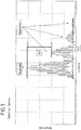
- FIG 3 shows an ultrasonic pulse that was generated with a conventional ultrasonic transducer.
- the conventional ultrasonic transducer known from the prior art consists of a piezo element on which a ⁇ / 4 layer was applied as a coupling layer. Both surfaces, that is to say the front and back of the coupling layer, do not have any structuring but show a planar course.
- the ultrasonic transducer is excited to vibrate through the thickness with a burst signal.
- the emitted ultrasonic pulse is recorded and the amplitude of the emitted ultrasonic pulse is determined as a function of the transit time in Figure 3 shown.
- the ultrasonic pulse has, in addition to a main echo, three easily recognizable side echoes, which are formed by secondary vibrations.
- the side echoes are caused by the Caused transverse vibrations of the piezo element.
- the side echoes contribute to the pulse width of the ultrasonic pulse of ⁇ L1.
- the difference between the amplitude of the main echo and the amplitude of the first secondary echo is ⁇ A1. It can be clearly seen that the side echoes significantly lengthen the pulse width of the ultrasonic pulse.
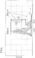
- Figure 4 shows the amplitude of an ultrasonic pulse as a function of the transit time, which was generated with an ultrasonic transducer according to the invention.
- the amplitude of the main echo is compared to the ultrasonic pulse that is generated with a conventional ultrasonic transducer (see Figure 3 ), unchanged. It can be clearly seen that the amplitude of the side echoes, which are formed by side vibrations, is greatly reduced compared to the ultrasonic pulse of a conventional ultrasonic transducer.
- ⁇ A2 is significantly larger than ⁇ A1.
- the following side echoes are also characterized by a lower amplitude.
- the ultrasonic pulse of the ultrasonic transducer according to the invention advantageously has only two side echoes, while the ultrasonic pulse of a conventional ultrasonic transducer has three side echoes ( Figure 3 ). The third side echo is completely attenuated.
- the pulse width of the ultrasonic pulse ⁇ L2 of the ultrasonic transducer according to the invention is significantly smaller than the pulse width of the ultrasonic pulse ⁇ L1 which was generated with a conventional ultrasonic transducer.
- the ultrasonic transducer according to the invention thus also has a larger relative bandwidth compared to the conventional ultrasonic transducer.
- An ultrasonic transducer is excited to vibrate thickly with a burst signal consisting of 5 vibrations at a frequency of 230 kHz.
- a coupling layer is applied to the piezo element, which is provided with linear cutouts on the front side, with all cutouts extending to the center of the coupling layer and being filled with air.
- the ultrasonic pulse emitted by the ultrasonic transducer has a pulse duration of approx. 100 ⁇ s and has a relative bandwidth of approx. 20%.
- An ultrasonic transducer is excited to vibrate thickly with a burst signal consisting of 5 vibrations at a frequency of 230 kHz.
- a coupling layer is applied to the piezo element, which is provided with linear recesses on the rear side, with all the recesses reaching different depths into the coupling layer and being filled with air.
- the ultrasonic pulse emitted by the ultrasonic transducer has a pulse duration of approx. 100 ⁇ s and has a relative bandwidth of approx. 20%.
- An ultrasonic transducer is excited to vibrate thickly with a burst signal consisting of 5 vibrations at a frequency of 230 kHz.
- a coupling layer is applied to the piezo element, the coupling layer having a structure that is formed by recesses that completely cut through the coupling layer and are filled with air.
- the ultrasonic pulse emitted by the ultrasonic transducer has a pulse duration of approx .30% up.
- An ultrasonic transducer is excited to vibrate thickly with a burst signal consisting of 5 vibrations at a frequency of 230 kHz.
- a coupling layer is applied to the piezo element, which is provided with linear recesses on the front, with all recesses extending to the middle of the coupling layer and being filled with NBR (copolymer of butadiene and acrylonitrile).
- the ultrasonic pulse emitted by the ultrasonic transducer has a pulse duration of around 50 ⁇ s and has a relative bandwidth of around 40%.
Landscapes
- Physics & Mathematics (AREA)
- Engineering & Computer Science (AREA)
- Chemical & Material Sciences (AREA)
- Biochemistry (AREA)
- General Physics & Mathematics (AREA)
- Health & Medical Sciences (AREA)
- Life Sciences & Earth Sciences (AREA)
- Analytical Chemistry (AREA)
- Pathology (AREA)
- General Health & Medical Sciences (AREA)
- Immunology (AREA)
- Acoustics & Sound (AREA)
- Multimedia (AREA)
- Ceramic Engineering (AREA)
- Mechanical Engineering (AREA)
- Investigating Or Analyzing Materials By The Use Of Ultrasonic Waves (AREA)
- Transducers For Ultrasonic Waves (AREA)
Priority Applications (1)
| Application Number | Priority Date | Filing Date | Title |
|---|---|---|---|
| EP19164629.8A EP3712607B1 (fr) | 2019-03-22 | 2019-03-22 | Transducteur ultrasonore doté d'une couche de couplage structurée |
Applications Claiming Priority (1)
| Application Number | Priority Date | Filing Date | Title |
|---|---|---|---|
| EP19164629.8A EP3712607B1 (fr) | 2019-03-22 | 2019-03-22 | Transducteur ultrasonore doté d'une couche de couplage structurée |
Publications (2)
| Publication Number | Publication Date |
|---|---|
| EP3712607A1 true EP3712607A1 (fr) | 2020-09-23 |
| EP3712607B1 EP3712607B1 (fr) | 2021-05-12 |
Family
ID=65904341
Family Applications (1)
| Application Number | Title | Priority Date | Filing Date |
|---|---|---|---|
| EP19164629.8A Active EP3712607B1 (fr) | 2019-03-22 | 2019-03-22 | Transducteur ultrasonore doté d'une couche de couplage structurée |
Country Status (1)
| Country | Link |
|---|---|
| EP (1) | EP3712607B1 (fr) |
Citations (2)
| Publication number | Priority date | Publication date | Assignee | Title |
|---|---|---|---|---|
| FR2546306A1 (fr) | 1983-05-20 | 1984-11-23 | Labo Electronique Physique | Appareil d'examen echographique de milieux aux ultrasons equipe d'un nouveau type de dispositif de transduction ultrasonore |
| WO1994005004A1 (fr) | 1992-08-13 | 1994-03-03 | Siemens Aktiengesellschaft | Transducteur ultrasonore |
-
2019
- 2019-03-22 EP EP19164629.8A patent/EP3712607B1/fr active Active
Patent Citations (2)
| Publication number | Priority date | Publication date | Assignee | Title |
|---|---|---|---|---|
| FR2546306A1 (fr) | 1983-05-20 | 1984-11-23 | Labo Electronique Physique | Appareil d'examen echographique de milieux aux ultrasons equipe d'un nouveau type de dispositif de transduction ultrasonore |
| WO1994005004A1 (fr) | 1992-08-13 | 1994-03-03 | Siemens Aktiengesellschaft | Transducteur ultrasonore |
Also Published As
| Publication number | Publication date |
|---|---|
| EP3712607B1 (fr) | 2021-05-12 |
Similar Documents
| Publication | Publication Date | Title |
|---|---|---|
| EP2559024B1 (fr) | Procédé pour commander un capteur ultrasonore et capteur ultrasonore | |
| EP0383972B1 (fr) | Transducteur ultrasonore à éléments de vibration trapézoidaux, et procédé et dispositif pour leur fabrication | |
| EP0840655B1 (fr) | Transducteur ultrasonore | |
| DE60203922T2 (de) | Vorrichtung und verfahren zur erzeugung von hochdruckultraschallimpulsen | |
| EP0308931B1 (fr) | Transducteurs à ultrasons avec une caractéristique d'émission et de réception astigmatique | |
| DE68907189T2 (de) | Verfahren zum Testen von Bauteilen eines impulsgesteuerten Tröpfchenaufzeichnungsgerätes. | |
| DE3526488A1 (de) | Ultraschall-wandler mit piezoelektrischem verbundmaterial | |
| DE102007045809A1 (de) | Detektorvorrichtung für ein Hindernis | |
| WO2004076046A1 (fr) | Procede et dispositif pour melanger de petites quantites de liquide dans des microcavites | |
| DE3733776A1 (de) | Ultraschallsonde | |
| DE102006055168A1 (de) | Hinderniserfassungsvorrichtung | |
| EP2031580B1 (fr) | Capteur à ultrasons doté d'un élément de support et d'une membrane, la membrane étant installée dans l'élément de support | |
| EP0308899A2 (fr) | Transducteur à ultrasons avec une caractéristique d'émission et réception astigmatique | |
| EP2734860B1 (fr) | Connexion de montage d'un véhicule automobile | |
| DE10047942B4 (de) | Sensorarray, Verfahren zum Herstellen eines Sensorarrays und Verwendung eines Sensorarrays | |
| EP3418736B1 (fr) | Procédé et dispositif de mesure de bande de largeur à l'aide d'un transducteur d'ultra-sons d'air multiélémentaire | |
| EP3712607B1 (fr) | Transducteur ultrasonore doté d'une couche de couplage structurée | |
| DE10139341A1 (de) | Ultraschallsensor mit einer Membran | |
| DE60319972T2 (de) | Zusammengesetzter piezoelektrischer körper | |
| DE19922965C2 (de) | Anordnung von mikromechanischen Ultraschallwandlern | |
| DE3008553A1 (de) | Schallkopf fuer untersuchungen mit ultraschall nach dem impuls-echoverfahren und mit diesem schallkopf ausgestattetes ultraschallgeraet | |
| DE102005022179B4 (de) | Ultraschallsonotrode | |
| WO2000017632A2 (fr) | Procede et dispositif pour detecter un defaut dans un rail de guidage | |
| EP1358476A2 (fr) | Capteur ultrasonique pour la commande de processus pour le soudage par resistance par points | |
| DE3784078T2 (de) | Echographie-wandler mit verbindungsschaltung. |
Legal Events
| Date | Code | Title | Description |
|---|---|---|---|
| PUAI | Public reference made under article 153(3) epc to a published international application that has entered the european phase |
Free format text: ORIGINAL CODE: 0009012 |
|
| STAA | Information on the status of an ep patent application or granted ep patent |
Free format text: STATUS: REQUEST FOR EXAMINATION WAS MADE |
|
| 17P | Request for examination filed |
Effective date: 20200115 |
|
| AK | Designated contracting states |
Kind code of ref document: A1 Designated state(s): AL AT BE BG CH CY CZ DE DK EE ES FI FR GB GR HR HU IE IS IT LI LT LU LV MC MK MT NL NO PL PT RO RS SE SI SK SM TR |
|
| AX | Request for extension of the european patent |
Extension state: BA ME |
|
| GRAP | Despatch of communication of intention to grant a patent |
Free format text: ORIGINAL CODE: EPIDOSNIGR1 |
|
| STAA | Information on the status of an ep patent application or granted ep patent |
Free format text: STATUS: GRANT OF PATENT IS INTENDED |
|
| INTG | Intention to grant announced |
Effective date: 20201023 |
|
| GRAS | Grant fee paid |
Free format text: ORIGINAL CODE: EPIDOSNIGR3 |
|
| GRAA | (expected) grant |
Free format text: ORIGINAL CODE: 0009210 |
|
| STAA | Information on the status of an ep patent application or granted ep patent |
Free format text: STATUS: THE PATENT HAS BEEN GRANTED |
|
| AK | Designated contracting states |
Kind code of ref document: B1 Designated state(s): AL AT BE BG CH CY CZ DE DK EE ES FI FR GB GR HR HU IE IS IT LI LT LU LV MC MK MT NL NO PL PT RO RS SE SI SK SM TR |
|
| REG | Reference to a national code |
Ref country code: GB Ref legal event code: FG4D Free format text: NOT ENGLISH |
|
| REG | Reference to a national code |
Ref country code: CH Ref legal event code: EP |
|
| REG | Reference to a national code |
Ref country code: DE Ref legal event code: R096 Ref document number: 502019001397 Country of ref document: DE |
|
| REG | Reference to a national code |
Ref country code: IE Ref legal event code: FG4D Free format text: LANGUAGE OF EP DOCUMENT: GERMAN |
|
| REG | Reference to a national code |
Ref country code: AT Ref legal event code: REF Ref document number: 1392505 Country of ref document: AT Kind code of ref document: T Effective date: 20210615 |
|
| REG | Reference to a national code |
Ref country code: LT Ref legal event code: MG9D |
|
| REG | Reference to a national code |
Ref country code: NL Ref legal event code: MP Effective date: 20210512 |
|
| PG25 | Lapsed in a contracting state [announced via postgrant information from national office to epo] |
Ref country code: HR Free format text: LAPSE BECAUSE OF FAILURE TO SUBMIT A TRANSLATION OF THE DESCRIPTION OR TO PAY THE FEE WITHIN THE PRESCRIBED TIME-LIMIT Effective date: 20210512 Ref country code: LT Free format text: LAPSE BECAUSE OF FAILURE TO SUBMIT A TRANSLATION OF THE DESCRIPTION OR TO PAY THE FEE WITHIN THE PRESCRIBED TIME-LIMIT Effective date: 20210512 Ref country code: FI Free format text: LAPSE BECAUSE OF FAILURE TO SUBMIT A TRANSLATION OF THE DESCRIPTION OR TO PAY THE FEE WITHIN THE PRESCRIBED TIME-LIMIT Effective date: 20210512 Ref country code: BG Free format text: LAPSE BECAUSE OF FAILURE TO SUBMIT A TRANSLATION OF THE DESCRIPTION OR TO PAY THE FEE WITHIN THE PRESCRIBED TIME-LIMIT Effective date: 20210812 |
|
| PG25 | Lapsed in a contracting state [announced via postgrant information from national office to epo] |
Ref country code: NO Free format text: LAPSE BECAUSE OF FAILURE TO SUBMIT A TRANSLATION OF THE DESCRIPTION OR TO PAY THE FEE WITHIN THE PRESCRIBED TIME-LIMIT Effective date: 20210812 Ref country code: LV Free format text: LAPSE BECAUSE OF FAILURE TO SUBMIT A TRANSLATION OF THE DESCRIPTION OR TO PAY THE FEE WITHIN THE PRESCRIBED TIME-LIMIT Effective date: 20210512 Ref country code: PL Free format text: LAPSE BECAUSE OF FAILURE TO SUBMIT A TRANSLATION OF THE DESCRIPTION OR TO PAY THE FEE WITHIN THE PRESCRIBED TIME-LIMIT Effective date: 20210512 Ref country code: SE Free format text: LAPSE BECAUSE OF FAILURE TO SUBMIT A TRANSLATION OF THE DESCRIPTION OR TO PAY THE FEE WITHIN THE PRESCRIBED TIME-LIMIT Effective date: 20210512 Ref country code: RS Free format text: LAPSE BECAUSE OF FAILURE TO SUBMIT A TRANSLATION OF THE DESCRIPTION OR TO PAY THE FEE WITHIN THE PRESCRIBED TIME-LIMIT Effective date: 20210512 Ref country code: PT Free format text: LAPSE BECAUSE OF FAILURE TO SUBMIT A TRANSLATION OF THE DESCRIPTION OR TO PAY THE FEE WITHIN THE PRESCRIBED TIME-LIMIT Effective date: 20210913 Ref country code: IS Free format text: LAPSE BECAUSE OF FAILURE TO SUBMIT A TRANSLATION OF THE DESCRIPTION OR TO PAY THE FEE WITHIN THE PRESCRIBED TIME-LIMIT Effective date: 20210912 Ref country code: GR Free format text: LAPSE BECAUSE OF FAILURE TO SUBMIT A TRANSLATION OF THE DESCRIPTION OR TO PAY THE FEE WITHIN THE PRESCRIBED TIME-LIMIT Effective date: 20210813 |
|
| PG25 | Lapsed in a contracting state [announced via postgrant information from national office to epo] |
Ref country code: NL Free format text: LAPSE BECAUSE OF FAILURE TO SUBMIT A TRANSLATION OF THE DESCRIPTION OR TO PAY THE FEE WITHIN THE PRESCRIBED TIME-LIMIT Effective date: 20210512 |
|
| PG25 | Lapsed in a contracting state [announced via postgrant information from national office to epo] |
Ref country code: EE Free format text: LAPSE BECAUSE OF FAILURE TO SUBMIT A TRANSLATION OF THE DESCRIPTION OR TO PAY THE FEE WITHIN THE PRESCRIBED TIME-LIMIT Effective date: 20210512 Ref country code: ES Free format text: LAPSE BECAUSE OF FAILURE TO SUBMIT A TRANSLATION OF THE DESCRIPTION OR TO PAY THE FEE WITHIN THE PRESCRIBED TIME-LIMIT Effective date: 20210512 Ref country code: SK Free format text: LAPSE BECAUSE OF FAILURE TO SUBMIT A TRANSLATION OF THE DESCRIPTION OR TO PAY THE FEE WITHIN THE PRESCRIBED TIME-LIMIT Effective date: 20210512 Ref country code: CZ Free format text: LAPSE BECAUSE OF FAILURE TO SUBMIT A TRANSLATION OF THE DESCRIPTION OR TO PAY THE FEE WITHIN THE PRESCRIBED TIME-LIMIT Effective date: 20210512 Ref country code: DK Free format text: LAPSE BECAUSE OF FAILURE TO SUBMIT A TRANSLATION OF THE DESCRIPTION OR TO PAY THE FEE WITHIN THE PRESCRIBED TIME-LIMIT Effective date: 20210512 Ref country code: RO Free format text: LAPSE BECAUSE OF FAILURE TO SUBMIT A TRANSLATION OF THE DESCRIPTION OR TO PAY THE FEE WITHIN THE PRESCRIBED TIME-LIMIT Effective date: 20210512 Ref country code: SM Free format text: LAPSE BECAUSE OF FAILURE TO SUBMIT A TRANSLATION OF THE DESCRIPTION OR TO PAY THE FEE WITHIN THE PRESCRIBED TIME-LIMIT Effective date: 20210512 |
|
| REG | Reference to a national code |
Ref country code: DE Ref legal event code: R097 Ref document number: 502019001397 Country of ref document: DE |
|
| PLBE | No opposition filed within time limit |
Free format text: ORIGINAL CODE: 0009261 |
|
| STAA | Information on the status of an ep patent application or granted ep patent |
Free format text: STATUS: NO OPPOSITION FILED WITHIN TIME LIMIT |
|
| 26N | No opposition filed |
Effective date: 20220215 |
|
| PG25 | Lapsed in a contracting state [announced via postgrant information from national office to epo] |
Ref country code: IS Free format text: LAPSE BECAUSE OF FAILURE TO SUBMIT A TRANSLATION OF THE DESCRIPTION OR TO PAY THE FEE WITHIN THE PRESCRIBED TIME-LIMIT Effective date: 20210912 Ref country code: AL Free format text: LAPSE BECAUSE OF FAILURE TO SUBMIT A TRANSLATION OF THE DESCRIPTION OR TO PAY THE FEE WITHIN THE PRESCRIBED TIME-LIMIT Effective date: 20210512 |
|
| PG25 | Lapsed in a contracting state [announced via postgrant information from national office to epo] |
Ref country code: IT Free format text: LAPSE BECAUSE OF FAILURE TO SUBMIT A TRANSLATION OF THE DESCRIPTION OR TO PAY THE FEE WITHIN THE PRESCRIBED TIME-LIMIT Effective date: 20210512 |
|
| PG25 | Lapsed in a contracting state [announced via postgrant information from national office to epo] |
Ref country code: MC Free format text: LAPSE BECAUSE OF FAILURE TO SUBMIT A TRANSLATION OF THE DESCRIPTION OR TO PAY THE FEE WITHIN THE PRESCRIBED TIME-LIMIT Effective date: 20210512 |
|
| REG | Reference to a national code |
Ref country code: CH Ref legal event code: PL |
|
| REG | Reference to a national code |
Ref country code: BE Ref legal event code: MM Effective date: 20220331 |
|
| PG25 | Lapsed in a contracting state [announced via postgrant information from national office to epo] |
Ref country code: LU Free format text: LAPSE BECAUSE OF NON-PAYMENT OF DUE FEES Effective date: 20220322 Ref country code: LI Free format text: LAPSE BECAUSE OF NON-PAYMENT OF DUE FEES Effective date: 20220331 Ref country code: IE Free format text: LAPSE BECAUSE OF NON-PAYMENT OF DUE FEES Effective date: 20220322 Ref country code: FR Free format text: LAPSE BECAUSE OF NON-PAYMENT OF DUE FEES Effective date: 20220331 Ref country code: CH Free format text: LAPSE BECAUSE OF NON-PAYMENT OF DUE FEES Effective date: 20220331 |
|
| PG25 | Lapsed in a contracting state [announced via postgrant information from national office to epo] |
Ref country code: BE Free format text: LAPSE BECAUSE OF NON-PAYMENT OF DUE FEES Effective date: 20220331 |
|
| P01 | Opt-out of the competence of the unified patent court (upc) registered |
Effective date: 20230517 |
|
| GBPC | Gb: european patent ceased through non-payment of renewal fee |
Effective date: 20230322 |
|
| PG25 | Lapsed in a contracting state [announced via postgrant information from national office to epo] |
Ref country code: GB Free format text: LAPSE BECAUSE OF NON-PAYMENT OF DUE FEES Effective date: 20230322 |
|
| PG25 | Lapsed in a contracting state [announced via postgrant information from national office to epo] |
Ref country code: GB Free format text: LAPSE BECAUSE OF NON-PAYMENT OF DUE FEES Effective date: 20230322 |
|
| PG25 | Lapsed in a contracting state [announced via postgrant information from national office to epo] |
Ref country code: MK Free format text: LAPSE BECAUSE OF FAILURE TO SUBMIT A TRANSLATION OF THE DESCRIPTION OR TO PAY THE FEE WITHIN THE PRESCRIBED TIME-LIMIT Effective date: 20210512 Ref country code: CY Free format text: LAPSE BECAUSE OF FAILURE TO SUBMIT A TRANSLATION OF THE DESCRIPTION OR TO PAY THE FEE WITHIN THE PRESCRIBED TIME-LIMIT Effective date: 20210512 |
|
| PG25 | Lapsed in a contracting state [announced via postgrant information from national office to epo] |
Ref country code: HU Free format text: LAPSE BECAUSE OF FAILURE TO SUBMIT A TRANSLATION OF THE DESCRIPTION OR TO PAY THE FEE WITHIN THE PRESCRIBED TIME-LIMIT; INVALID AB INITIO Effective date: 20190322 |
|
| PG25 | Lapsed in a contracting state [announced via postgrant information from national office to epo] |
Ref country code: MT Free format text: LAPSE BECAUSE OF FAILURE TO SUBMIT A TRANSLATION OF THE DESCRIPTION OR TO PAY THE FEE WITHIN THE PRESCRIBED TIME-LIMIT Effective date: 20210512 |
|
| REG | Reference to a national code |
Ref country code: AT Ref legal event code: MM01 Ref document number: 1392505 Country of ref document: AT Kind code of ref document: T Effective date: 20240322 |
|
| PG25 | Lapsed in a contracting state [announced via postgrant information from national office to epo] |
Ref country code: AT Free format text: LAPSE BECAUSE OF NON-PAYMENT OF DUE FEES Effective date: 20240322 |
|
| PG25 | Lapsed in a contracting state [announced via postgrant information from national office to epo] |
Ref country code: TR Free format text: LAPSE BECAUSE OF FAILURE TO SUBMIT A TRANSLATION OF THE DESCRIPTION OR TO PAY THE FEE WITHIN THE PRESCRIBED TIME-LIMIT Effective date: 20210512 |
|
| PGFP | Annual fee paid to national office [announced via postgrant information from national office to epo] |
Ref country code: DE Payment date: 20260331 Year of fee payment: 8 |
|
| PGFP | Annual fee paid to national office [announced via postgrant information from national office to epo] |
Ref country code: AT Payment date: 20260410 Year of fee payment: 5 |