EP3712657A1 - Verbessertes sichtsystem für luftfahrzeug, entsprechendes luftfahrzeug und sichtverfahren - Google Patents
Verbessertes sichtsystem für luftfahrzeug, entsprechendes luftfahrzeug und sichtverfahren Download PDFInfo
- Publication number
- EP3712657A1 EP3712657A1 EP20163593.5A EP20163593A EP3712657A1 EP 3712657 A1 EP3712657 A1 EP 3712657A1 EP 20163593 A EP20163593 A EP 20163593A EP 3712657 A1 EP3712657 A1 EP 3712657A1
- Authority
- EP
- European Patent Office
- Prior art keywords
- transmitters
- receivers
- group
- network
- virtual
- Prior art date
- Legal status (The legal status is an assumption and is not a legal conclusion. Google has not performed a legal analysis and makes no representation as to the accuracy of the status listed.)
- Granted
Links
Images





Classifications
-
- G—PHYSICS
- G01—MEASURING; TESTING
- G01S—RADIO DIRECTION-FINDING; RADIO NAVIGATION; DETERMINING DISTANCE OR VELOCITY BY USE OF RADIO WAVES; LOCATING OR PRESENCE-DETECTING BY USE OF THE REFLECTION OR RERADIATION OF RADIO WAVES; ANALOGOUS ARRANGEMENTS USING OTHER WAVES
- G01S13/00—Systems using the reflection or reradiation of radio waves, e.g. radar systems; Analogous systems using reflection or reradiation of waves whose nature or wavelength is irrelevant or unspecified
- G01S13/88—Radar or analogous systems specially adapted for specific applications
- G01S13/91—Radar or analogous systems specially adapted for specific applications for traffic control
- G01S13/913—Radar or analogous systems specially adapted for specific applications for traffic control for landing purposes
-
- G—PHYSICS
- G08—SIGNALLING
- G08G—TRAFFIC CONTROL SYSTEMS
- G08G5/00—Traffic control systems for aircraft
- G08G5/70—Arrangements for monitoring traffic-related situations or conditions
- G08G5/74—Arrangements for monitoring traffic-related situations or conditions for monitoring terrain
-
- B—PERFORMING OPERATIONS; TRANSPORTING
- B64—AIRCRAFT; AVIATION; COSMONAUTICS
- B64D—EQUIPMENT FOR FITTING IN OR TO AIRCRAFT; FLIGHT SUITS; PARACHUTES; ARRANGEMENT OR MOUNTING OF POWER PLANTS OR PROPULSION TRANSMISSIONS IN AIRCRAFT
- B64D45/00—Aircraft indicators or protectors not otherwise provided for
- B64D45/04—Landing aids; Safety measures to prevent collision with earth's surface
- B64D45/08—Landing aids; Safety measures to prevent collision with earth's surface optical
-
- G—PHYSICS
- G01—MEASURING; TESTING
- G01C—MEASURING DISTANCES, LEVELS OR BEARINGS; SURVEYING; NAVIGATION; GYROSCOPIC INSTRUMENTS; PHOTOGRAMMETRY OR VIDEOGRAMMETRY
- G01C23/00—Combined instruments indicating more than one navigational value, e.g. for aircraft; Combined measuring devices for measuring two or more variables of movement, e.g. distance, speed or acceleration
- G01C23/005—Flight directors
-
- G—PHYSICS
- G01—MEASURING; TESTING
- G01S—RADIO DIRECTION-FINDING; RADIO NAVIGATION; DETERMINING DISTANCE OR VELOCITY BY USE OF RADIO WAVES; LOCATING OR PRESENCE-DETECTING BY USE OF THE REFLECTION OR RERADIATION OF RADIO WAVES; ANALOGOUS ARRANGEMENTS USING OTHER WAVES
- G01S13/00—Systems using the reflection or reradiation of radio waves, e.g. radar systems; Analogous systems using reflection or reradiation of waves whose nature or wavelength is irrelevant or unspecified
- G01S13/003—Bistatic radar systems; Multistatic radar systems
-
- G—PHYSICS
- G01—MEASURING; TESTING
- G01S—RADIO DIRECTION-FINDING; RADIO NAVIGATION; DETERMINING DISTANCE OR VELOCITY BY USE OF RADIO WAVES; LOCATING OR PRESENCE-DETECTING BY USE OF THE REFLECTION OR RERADIATION OF RADIO WAVES; ANALOGOUS ARRANGEMENTS USING OTHER WAVES
- G01S13/00—Systems using the reflection or reradiation of radio waves, e.g. radar systems; Analogous systems using reflection or reradiation of waves whose nature or wavelength is irrelevant or unspecified
- G01S13/86—Combinations of radar systems with non-radar systems, e.g. sonar, direction finder
- G01S13/867—Combination of radar systems with cameras
-
- G—PHYSICS
- G01—MEASURING; TESTING
- G01S—RADIO DIRECTION-FINDING; RADIO NAVIGATION; DETERMINING DISTANCE OR VELOCITY BY USE OF RADIO WAVES; LOCATING OR PRESENCE-DETECTING BY USE OF THE REFLECTION OR RERADIATION OF RADIO WAVES; ANALOGOUS ARRANGEMENTS USING OTHER WAVES
- G01S13/00—Systems using the reflection or reradiation of radio waves, e.g. radar systems; Analogous systems using reflection or reradiation of waves whose nature or wavelength is irrelevant or unspecified
- G01S13/88—Radar or analogous systems specially adapted for specific applications
- G01S13/89—Radar or analogous systems specially adapted for specific applications for mapping or imaging
-
- G—PHYSICS
- G08—SIGNALLING
- G08G—TRAFFIC CONTROL SYSTEMS
- G08G5/00—Traffic control systems for aircraft
- G08G5/20—Arrangements for acquiring, generating, sharing or displaying traffic information
- G08G5/21—Arrangements for acquiring, generating, sharing or displaying traffic information located onboard the aircraft
-
- H—ELECTRICITY
- H01—ELECTRIC ELEMENTS
- H01Q—ANTENNAS, i.e. RADIO AERIALS
- H01Q1/00—Details of, or arrangements associated with, antennas
- H01Q1/27—Adaptation for use in or on movable bodies
- H01Q1/28—Adaptation for use in or on aircraft, missiles, satellites, or balloons
- H01Q1/281—Nose antennas
-
- H—ELECTRICITY
- H01—ELECTRIC ELEMENTS
- H01Q—ANTENNAS, i.e. RADIO AERIALS
- H01Q1/00—Details of, or arrangements associated with, antennas
- H01Q1/27—Adaptation for use in or on movable bodies
- H01Q1/28—Adaptation for use in or on aircraft, missiles, satellites, or balloons
- H01Q1/286—Adaptation for use in or on aircraft, missiles, satellites, or balloons substantially flush mounted with the skin of the craft
Definitions
- the invention applies to aircraft used in civil aviation, in particular in business aviation.
- Such a system is intended in particular to provide the crew of the aircraft, during the approach or taxiing phases with low or no visibility, an improved view of the environment situated opposite the aircraft.
- the system is intended in particular to obtain an image of the terrain and in particular of a landing strip, during the approach of the aircraft towards the landing strip, or / and a display of characteristics of the landing strip. landing, such as its contour, its axis or / and its threshold, positioned relative to the aircraft.
- Aircraft frequently operate in degraded weather conditions, which include low cloud, fog, or / and rain.
- An alternative to guidance systems is a vision system, using one or more sensors, on board the aircraft, allowing the pilot to view the runway with sufficient notice to make the decision to continue the approach at low altitude. until landing.
- the vision system is also useful for the pilot in order to apprehend the terrain located in the vicinity of the runway.
- EFVS enhanced Flight Vision System
- Known improved vision systems use, for example, optronic sensors in visible and infrared bands. These systems are generally able to produce a good quality image for the crew. However, under certain particularly degraded conditions, in particular in the presence of dense fog or / and a low cloudy ceiling, the optical systems exhibit performances which limit their use by the crew.
- aircraft are generally equipped with weather radars with mechanical scanning antennas.
- Radars or radiometers operating at higher transmission frequencies than meteorological radars can be more compact.
- these sensors are not capable of performing the functions performed by meteorological radars, the latter must therefore be kept on board the aircraft.
- the existing higher transmission frequency sensors therefore also pose integration problems, due to the lack of available space on the aircraft. Added to this is the difficulty of designing a radome which is both transparent in these frequency bands and exhibits the mechanical and aerodynamic properties necessary for its integration into an aircraft.
- An object of the invention is to offer an improved vision system which has a range and an adequate resolution for observing an approaching landing runway, even in very degraded meteorological conditions, the system having a reduced size, a speed cooling, and little or no moving parts.
- the invention relates to an improved vision system of the aforementioned type, characterized in that the vision sensor is an electromagnetic sensor comprising a plurality of transmitters of a transmitted signal, the transmitters constituting at least one group. of transmitters and a plurality of receivers of a received signal, resulting from the signal transmitted after reflection in the field, the receivers constituting at least one group of receivers, the electromagnetic sensor comprising a set of waveform generation feeding each transmitter to generate the transmitted signal and a set for capturing the signal received by each receiver after reflection in the field, the transmitters being distinct and spaced apart from the receivers being arranged to generate, from each combination formed of a transmitter and a receiver, between the group of transmitters and the group of receivers, at least one network of transmitters / virtual receivers extending in a direction of elongation transverse to the direction of observation, the linear density of virtual transmitters / receivers in the array along the direction of elongation being greater than the line density of emitters in the group of emitters along the direction of
- the subject of the invention is also an aircraft comprising an improved vision system as defined above, the display being placed in a cockpit of the aircraft.
- An aircraft 10, equipped with an improved vision system 12 according to the invention, is illustrated schematically on the figures 1 and 2 .
- the aircraft 10 comprises a fuselage 14 having at the front a forward point 16 situated upstream of a cockpit 18 of the aircraft.
- the cockpit 18 comprises in a known manner a windshield 20 allowing the crew members to observe outside the aircraft.
- the front tip 16 comprises, at the front of the windshield 20, a front cone composed of an intermediate region 22 which is substantially frustoconical and a radome 24 closing off the intermediate region 22 at the front end of the aircraft 10.
- the radome 24 is made of a material transparent to electromagnetic waves at frequencies corresponding to a weather radar.
- the intermediate region 22 is for example made of metal. In this example, it defines a recess 26 closed at the rear by a window 28.
- the recess 26 is for example as described in the French application FR 2 996 522 of the Applicant.
- the vision system 12 is intended to offer the crew of the aircraft an improved vision of the environment in front of the aircraft.
- the vision system 12 is intended to provide an image of the terrain located in front of and lower than the aircraft 10.
- the image illustrates the actual appearance of the terrain, in particular of a landing strip. and the ground around the airstrip.
- the angular resolution of the image obtained is for example between 0.2 ° and 1.2 °.
- the vision system 12 is able to observe terrain advantageously located at a distance of less than 5000 m from the aircraft, on a bearing of between -20 ° and + 20 °, taken with respect to a central direction of observation D.
- the terrain is for example an airfield on which the aircraft is about to land or on which the aircraft is taxiing on the ground, with the obstacles that it contains.
- the vision system 12 comprises an electromagnetic sensor 30 suitable for emitting electromagnetic signals towards the terrain and for collecting the signals reflected from the terrain, a processing unit 32 suitable for processing the reflected signals to form a reflectivity map of the terrain situated opposite, and a display 34, intended to display in real time an image of the terrain formed by the processing unit 32 from the reflectivity map, or / and information obtained from the reflectivity map reconstituted by the processing unit 32, based on the data received from the electromagnetic sensor 30.
- the vision system 12 further comprises an optical sensor 36 connected to the processing unit 32 and to the display 34.
- the set of optical sensors 36 advantageously operates in the visible and / or near infrared range and / or infra-red.
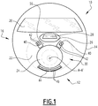
- the electromagnetic sensor 30 comprises at least one group of transmitters 42 of an electromagnetic signal, in particular a line 40 of transmitters 42 of an electromagnetic signal intended to be sent to the field, and at least one group of receivers 46 , in particular a line 44 of receivers 46, the receivers 46 being intended to receive the signals reflected in the field, the emitters 42 being located away from the receivers 46.
- the lines 40, 44 are formed in a transverse plane ⁇ substantially perpendicular to the plane axis AA '(see figure 2 ), for example forming an angle between 75 ° and 90 ° with the plane axis A-A '.
- the central direction of observation D is perpendicular to the plane ⁇ .
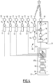
- the electromagnetic sensor 30 further comprises an assembly 48 for generating a waveform, capable of simultaneously supplying each transmitter 42, and an assembly 50 for capturing the signal received by each receiver 46, after reflection in the field.
- the transmitters 42 are distinct and spaced from the receivers 46.
- the transmitters 42 and the receivers 46 are arranged to generate, from each combination formed of a transmitter 42 and a receiver 46, a continuous network of transmitters / receivers virtual 54 extending between the group of transmitters 42 and the group of receivers 46, along a direction of elongation A transverse to the direction of observation D.
- the direction of elongation A is perpendicular to the direction of observation D and is horizontal when the aircraft axis AA 'is horizontal, the wings being flat.
- the transmitters 42 are arranged according to a first step nP on each line 40, the receivers 46 being arranged according to a second step mP on each line. line 44, the pitches nP and mP being measured in projection on the direction of elongation A.
- the numbers n and m are whole numbers prime between them, for example 3 and 5 or 2 and 3 or 3 and 2.
- the pitch P / 2 is a distance generally less than the wavelength of the transmitted signal, in particular between 0.4 times and 0.6 times the wavelength of the transmitted signal.
- Each transmitter 42 is for example made up of an elementary antenna flush with the skin of the intermediate region 22, devoid of a retraction mechanism.
- Each elementary antenna transmits grazing, with a grazing angle for example between 5 ° and 30 °.
- the shaving angle is defined as the angle to the plane tangent to the surface of the elementary antenna on the skin of the intermediate region 22.
- the skin of the aircraft is the external surface of the aircraft in contact with the mass of air in which the aircraft circulates.
- An example of an elementary antenna is a leakage wave antenna.
- This example of an antenna offers the advantage of being flush, which makes it possible to minimize the impact of its integration on an aircraft, such as, for example, hindering the aerodynamic flow of air on the surface of the aircraft.
- the antenna advantageously comprises an elongated dielectric with metallized faces. A network of slots is made in the metallization of the upper face. The length of the slots as well as the width of the guide follow a law of gradual evolution configured so that the slots do not create a return wave.
- the elementary antenna comprises an upstream resonant cavity supplying the waveguide and a downstream resonant cavity to collect the residual energy and dissipate it in a load, so as not to create a return wave in the guide.
- the receptors 46 are flush with the skin of the intermediate region 22 and are devoid of a retraction mechanism. They have a surface almost perpendicular to the direction of reception. They are formed from the same elementary antennas as the transmitters 42.
- each line of transmitters 42 is located on an upper surface of the skin of the intermediate region 22, above the plane axis A-A ', the line of receivers 46 being located on a lower surface of the skin of the the intermediate region 22, below the aircraft axis A-A '.
- Each line 40 of transmitters 42 and each line 44 of receivers 46 is here a curved line.
- the curved line is for example an arc of a circle.
- the curvature advantageously adapts to the shape of the airplane, in particular to minimize the impact of the integration of the antennas on the airplane.
- the line 40 of transmitters 42 here has a concavity directed towards the plane axis A-A ', and the line 44 of receivers 46 also has a concavity directed towards the plane axis AA' directed towards the plane. concavity of line 40 of transmitters 42.
- the transmitters 42 of each line 40 being located away from the receivers 46 of each line 44, the transmissions made using the transmitters 42 and received on the receivers 46 create the dense network of virtual transmitters / receivers 54 by their barycenter.
- the network of virtual transmitters / receivers 54 results from the successive interactions of each transmitter 42 with a plurality of receivers 46 of the line 44, advantageously with all the receivers 46 of the line 44, to form the line 52 of transmitters / virtual receivers 54 at their barycenter.
- the network of virtual transmitters / receivers 54 is continuous. To this end, the maximum distance separating two adjacent virtual transmitters / receivers 54, projected on the direction of elongation A is advantageously less than the pitch P defined above.
- the linear density of virtual transmitters / receivers 54 in the continuous network of virtual transmitters / receivers 54, projected along the direction of elongation A is greater than the linear density of transmitters 42 in the group of transmitters 42, projected along the direction of elongation A and is greater than the linear density of receptors 46 in the group of receptors 46, projected along the direction of elongation A.
- the number of real radiating transmitters 42 therefore remains very limited compared to the number of virtual radiating transmitters / receivers 54.
- the sensor 30 comprises a first line 40 of transmitters 42 located on one side of a vertical plane passing through the aircraft axis A-A ', and a second line 40 of transmitters 42 located on the other side of the plane.
- vertical plane passing through the plane axis AA ' symmetrically with respect to the first line 40.
- the lines 40 of emitters 42 define between them a gap area 56 devoid of emitters 42.
- This gap area 56 is advantageously intended to receive the optical sensor 36, when such a sensor 36 is present on the aircraft.
- the gap area 56 advantageously has a width, taken parallel to the direction of elongation A, greater than 5 times the pitch P.
- the first line 40 of emitters 42 and the second line 40 of emitters 42 are located substantially on arcs of the same circle in projection in the plane ⁇ containing the transmitters 42.
- the line 44 of receivers 46 is situated substantially on an arc of the same circle.
- the network of virtual transceivers 54 forms a line or a pseudo line 52 extending in the direction of extension.
- the network of virtual transmitters / receivers 54 When it forms a “pseudo line”, the network of virtual transmitters / receivers 54 generally has a height, taken perpendicular to the direction of elongation A in the plane ⁇ , less than, advantageously less than 0.1 times the extent longitudinal of the virtual transmitter / receiver array 54, taken along the direction of elongation A.
- the height of the virtual transmitter / receiver network 54 is notably less than 10 times the pitch P.
- the network of virtual transmitters / receivers 54 includes a first lateral sub-network 58A resulting from interactions between each transmitter 42 of the first line 40 of transmitters 42 and each receiver 46 of the line 44 of receivers 46 and a second lateral sub-network 58B comprising virtual transmitters / receivers 54 resulting from the interaction between a transmitter 42 of the second line 40 of transmitters 42 and the receivers 46 of line 44.
- the subnetworks 58A, 58B have a common end 60.
- the subnetworks 58A, 58B each comprise a plurality of lines 61A, 61B, 61C of virtual transceivers 54 at least partly superimposed towards the common end 60 and diverging away from the common end 60.
- Each line 61A, 61B, 61C results from the interaction between a single transmitter 42 of the second line 40 of transmitters 42 and a plurality of receivers 46 of the line 44, advantageously all of them. line 44 receivers.
- the sub-networks 58A, 58B thus form a pseudo-line, as defined above, with a low vertical dispersion, despite the implantation curvature of the lines 40 of transmitters 42 and of the line 44 of receivers 46.
- the relative arrangement of the line 40 of transmitters 42 and of the line 44 of receivers 46 maximizes the decoupling between the transmitters 42 and the receivers 46 by placing the transmitters 42 above the aircraft axis AA 'and the receivers 46 in below the aircraft axis A-A '.
- the gap area 56 makes it possible to integrate another sensor, in particular the optical sensor 36, without interaction between the emitters 42 of each line 40 and the receivers 46 of the line 44.
- each line 40 of transmitters 42 advantageously comprises between 2 and 10 transmitters, in particular three transmitters 42.
- the line 44 of receivers 46 comprises a number of receivers 46 advantageously greater than the number of transmitters 42.
- the number of receivers 46 is for example greater than ten, in particular equal to twenty-four. The number of receivers 46 remains below 40.
- a line 52 of virtual transmitters / receivers 54 comprising more than fifty transmitters / receivers 54 is generated, in particular comprising one hundred and thirty-eight virtual transmitters / receivers 54 in the example of figure 3 .
- the waveform generation assembly 48 is suitable for simultaneously supplying each transmitter 42 of each line 40 with a periodic electromagnetic signal, in particular sinusoidal, in a range of frequencies comprised in particular between 8 GHz and 100 GHz, in particular between 28 GHz and 35 GHz, preferably between 31.8 GHz and 33.4 GHz.
- the waveform generation unit 48 is suitable for simultaneously supplying all the transmitters 42 on frequency bands spaced apart in frequency by a difference for example greater than 20 KHz, in particular between 50 KHz and 150 KHz. .
- Each transmitter 42 of each line 40 is thus able to transmit at each instant at a frequency distinct from the other transmitters 42 of line 40.
- the frequency of the transmitted signal is periodically modulated according to a predetermined waveform.
- the waveform is advantageously continuous emission, for example of the FMCW type (“Frequency Modulation Continuous Wave” or “Continuous Wave with Frequency Modulation”).
- the peak power transmitted by the transmitters 42 is very low, since it is equal to its average power. This confers an advantage important in terms of electromagnetic compatibility for system integration and also in terms of component cost.
- the senor 30 does not have a blind distance, that is to say a minimum detection distance. This allows its use even at very short distance.
- the modulation of the periodic frequency signal increases or / and decreases with each period of the waveform.
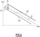
- the modulation over a period T of the waveform is in the form of a decreasing linear ramp at each period T, as illustrated by figure 5 which represents the modulation frequency of the signals 60A, 60B, 60C, 60D 60E and 60F of the respective transmitters 42 of each line 40.
- the frequency variation as a function of time is linear over period T.
- the frequency difference between the start of each period and the end of each period is for example greater than 10 MHz, in particular between 12 MHz and 350 MHz.
- Signals 60A to 60F are shifted from each other by a constant frequency over time.
- the modulation of the periodic frequency signal increases in a first part of the period T and decreases in a second part of the period T. It advantageously presents an increasing linear ramp, followed by a decreasing linear ramp.
- the waveform generation assembly 48 includes a reference oscillator 70, a waveform generator 72 from the signal generated by oscillator 70, and advantageously a power amplifier 76.
- the reference oscillator 70 is suitable for generating an excitation signal at a frequency in particular between 8 GHz and 100 GHz, in particular between 28 GHz and 35 GHz, preferably between 31.8 GHz and 33.4 GHz.
- the generator 72 is intended to create and ensure a waveform with a linear ramp of frequency modulation as a function of time over each period T.
- a conjugate 78 of the transmitted signal is suitable for being extracted from the generator 72 in order to be mixed with the signal received by the capture assembly 50.
- the generator 72 is able to create the modulation ramp suitable for each transmitter 42 with the frequency offset chosen with respect to the frequency modulation of the other transmitters 42.
- the power amplifier 76 is disposed downstream of the modulated signal to amplify this signal with a view to its transmission to the transmitter 42.
- each transmitter 42 is therefore a sinusoidal signal, the frequency of which is sawtooth modulated around a carrier.
- the capture assembly 50 is suitable for capturing the signals received by each receiver 46 after reflection in the field and for determining a delay ⁇ t between the signals transmitted and the signals received.
- the delay ⁇ t generates a frequency shift between the signal transmitted by the transmitter 42 and the signal received by the receiver 46 coming from the transmitter 42 at each instant t.
- the frequency shift at each instant t between the transmitted signal 60A and the received signal 80A resulting from the transmission of the signal 60A comprises a contribution 82 linked to the delay ⁇ t of the signal received with respect to the transmitted signal and a contribution 84 linked to l Doppler effect due to the movement of the aircraft 10 relative to the terrain.
- the contribution linked to Doppler is calculated by knowing the speed of the aircraft 10 relative to the terrain using a ground speed sensor present in the aircraft 10, in particular a GPS or an inertial unit.
- the capture assembly 50 comprises a low noise amplifier 90, intended to amplify the signal received by each receiver 46, a mixer 92, intended to receive the conjugate 78 of the signal transmitted by one or more transmitters 42, a low-pass filter 94, intended to eliminate the harmonics resulting from the mixture in the mixer 92, and an analog-to-digital converter 96.
- the processing unit 32 comprises for example a processor and a memory comprising software components suitable for being executed by the processor.
- the components are made at least partially in the form of programmable logic components, or in the form of dedicated integrated circuits.
- the processing unit 32 comprises a component 97A for separating in the signal received by each receiver 46 the signals transmitted by each transmitter 42 in order to restore the signal from each virtual transmitter / receiver 54 and a component 97B for filtering each signal received by each virtual transmitter / receiver 54 as a function of the direction with respect to the direction of observation, in particular as a function of a bearing relative to the direction of observation.
- the processing unit 32 further comprises a component 98 for calculating a fast Fourier transform on the filtered signals in order to apply a distance filtering and a component 99 for establishing an image of the terrain from the signals filtered in management function.
- the component 97A is for example a frequency filter, suitable for separating the signals received on each receiver 46 as a function of the shifted frequencies transmitted by each transmitter 42, in order to generate the signal received on the corresponding virtual transmitter / receiver 54.
- Component 97B is configured to perform a computational beam forming (“Digital Beam Forming”) capable of sorting the signal according to the direction from which it was received.
- Digital Beam Forming Digital Beam Forming
- the computational beamforming is able to capture the signals received on each virtual transceiver 54 and sort the information obtained to filter signals according to the direction from which it was received, and thereby perform filtering in. deposit.
- the component 98 is able to apply a Fourier transform to the signal from each direction and thus obtain a frequency line representative of the contribution of the delay ⁇ t (the Doppler contribution having been extracted) to provide distance filtering.
- the component 99 is suitable for obtaining from the components 97B and 98 power information received as a function of the direction and of the distance in order to construct a reflectivity map measured in the direction of observation D.
- the component 99 is suitable for reconstituting an image with a contrast depending on the reflectivity measured in the viewing direction D using the received power.
- This contrast makes it possible in particular to identify differences between an airstrip or access routes to the runway, generally with reflectivity in the weaker viewing direction D, and the ground surrounding the runway, generally with greater reflectibility in the viewing direction D.
- An image of the terrain located in the direction of sight of the sensor 30 can therefore be obtained for a bearing for example between -20 ° and + 20 ° at distances less than 5,000 m and in particular between 5 m and 10,000 m.
- the waveform generation assembly 48 turns on.
- the reference oscillator 70 generates a periodic signal, in particular a sinusoidal signal, and this signal is modulated by the generator 72 at the frequency suitable for the relevant transmitter 42, according to the waveform described above.
- a portion of the signal is then conjugated to form a conjugated signal 78 for capture assembly 50.
- Each transmitter 42 of each line 40 is powered simultaneously to generate a periodic electromagnetic signal, the frequency of which is modulated around a carrier, according to a waveform with periodic continuous emission described above.
- the periodic signal is generated in a frequency band between 8 GHz and 100 GHz, in particular between 28 GHz and 35 GHz, preferably between 31.8 GHz and 33.4 GHz.
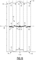
- the modulation advantageously comprises, at each period of the waveform, a decreasing frequency ramp from a maximum frequency to a minimum frequency, or as on the figure 9 an increasing ramp followed by a decreasing ramp.
- the frequency ramps 60A to 60F of the different transmitters 42 are frequency offset with respect to each other by a frequency offset, for example greater than 20 KHz, in particular between 50 KHz and 150 KHz.
- the transmitted signal is reflected in the field to be also received continuously on the receivers 46.
- This signal is delayed, which induces a linear shift in frequency with respect to the transmitted signal, this linear shift also including a Doppler effect.
- the assembly 50 captures each signal received on each receiver 46 and mixes these signals with one or more conjugates of the transmitted signals in order to extract therefrom a signal representative of a frequency difference between the transmitted signal and the received signal.
- the low pass filter 94 removes the harmonics resulting from the mixture.
- the signal obtained is then digitized in the analog-to-digital converter 96.
- the signal transmitted from the transmitters 42 and received at the level of the receivers 46 is equivalent to the signal which would have received a plurality of virtual transmitters / receivers 54 located at the barycenter of the real transmitters 42 and 46 receivers.
- a continuous network of virtual transmitters / receivers 54 of much greater density and of pitch equal to P / 2 is thus formed with a pitch of the virtual network of the order of half the wavelength of the transmitted signal.
- the component 97A of the processing unit 32 recovers all of the signals received on the virtual transmitters / receivers 54 at each instant and the component 97B forms a beam by the calculation from the signals received to sort the signal according to the direction from which it was received.
- the component 98 applies a Fourier transform and thus performs a distance filtering.
- the component 99 then collects from the components 97B, 98 power information received as a function of the distance and the bearing, deduces therefrom a reflectivity map, and forms an image on the basis of the reflectivity map.
- Images of the terrain or / and information obtained from the reflectivity map are displayed on the display 34 at a frequency greater than 0.5 Hz, in particular greater than 2 Hz. This allows the crew to distinguish details of the terrain located forward and lower than the aircraft, in particular a contrast between the surface of a runway or an access route and the ground on the ground. vicinity of this coating.
- the crew can thus observe the presence and the location of an airstrip, at a suitable height to make a decision, even if the visibility is very low, or even almost zero.
- optical sensor 36 is used in combination or alternatively to electromagnetic sensor 30.
- the arrangement of the optical sensor 36 in the gap area 56 between the lines 44 of emitters 42 avoids mechanical interference between the optical sensor 36 and the electromagnetic sensor 30, while ensuring the correct individual operation of each of the sensors 30, 36.
- the line 40 of transmitters 42 and the line 44 of receivers 46 of the electromagnetic sensor are located on a rule placed below the Karman of the aircraft.
- the lines 40, 44 are then straight, and parallel to one another.
- the number of transmitters 42 is for example equal to or greater than that described above and the number of receivers 46 is for example equal to or greater than that described previously.
- the continuous network of transmitters / receivers 54 is then a straight line 52 of virtual transmitters / receivers, parallel to the lines 40, 44 and located between these lines 40, 44.
- the installation under the Karman makes it possible to have an electromagnetic sensor 30 of considerable length and linear offering permanent visibility of the runway during the approach.
- the significant length has the advantage of providing a greater resolution of the image in bearing.
- the real network of transmitters 42 and receivers 46 is also flush and devoid of moving elements.
- the electromagnetic sensor 30 is easily implantable on the aircraft, without modifying its external structure and without affecting its aerodynamic performance.
- the simultaneous powering of all the transmitters 42 with a frequency modulation specific to each transmitter 42 corresponds to a simultaneous transmission on a virtual network of transmitters / receivers 54 of great density. This allows the processing unit 32 to perform beamforming by calculation, and therefore to obtain an image with a high bearing and distance aperture.
- Beam formation by calculation also makes it possible to obtain observation rates which are not attainable by a mechanical scanning antenna, while avoiding the use of mechanical elements and moving parts.
- the implantation in the intermediate region 22 is also very advantageous in that it avoids coupling with other mobile elements of the aircraft such as the landing gears. It also allows maximum decoupling between the transmitters 42 and the receivers 46.
- the presence of a gap area 56 allows in besides integrating an optical sensor 36 without interaction with the electromagnetic sensor 30.
- the senor 30 comprises a first line 44 of receivers 46 located on one side of a vertical plane passing through the aircraft axis AA 'and a second line 44 of receivers 46 located on the other side of the vertical plane passing through l 'plane axis A-A', symmetrically with respect to the first line 44.
- the lines 44 of receivers 46 delimit between them a lacunar area 56 devoid of transmitters 42, of width, taken parallel to the direction of elongation A greater than 5 times the pitch P.
- the senor 30 comprises a third line 40 of transmitters 42 located between the first line 40 of transmitters 42 and the second line 40 of transmitters 42.
- the first line 40 and the third line 40 define between them a lacunar zone 56 of width, taken parallel to the direction of elongation A greater than 5 times the pitch P.
- the third line 40 and the second line 40 delimit between them a gap area 56 of width, taken parallel to the direction of elongation A greater than 5 times the pitch P.
- the subnetworks 58 formed of the virtual transmitters / receivers 54 resulting from the interaction between the transmitters 42 of a single line 40 and the receivers 46 of a single line 44 define a network of virtual transceivers 54 continuous in the direction of elongation A.
- the network here retains the shape of a pseudo line 52 along the Z axis perpendicular to the direction of elongation A.
- the senor 30 comprises several networks of virtual transceivers 54 each forming a line or a pseudo-line 52 parallel to the same direction of elongation A, the networks being spaced vertically from one another.
Landscapes
- Engineering & Computer Science (AREA)
- Remote Sensing (AREA)
- Radar, Positioning & Navigation (AREA)
- Physics & Mathematics (AREA)
- General Physics & Mathematics (AREA)
- Aviation & Aerospace Engineering (AREA)
- Computer Networks & Wireless Communication (AREA)
- Astronomy & Astrophysics (AREA)
- Electromagnetism (AREA)
- Radar Systems Or Details Thereof (AREA)
- Measurement Of Length, Angles, Or The Like Using Electric Or Magnetic Means (AREA)
- Geophysics And Detection Of Objects (AREA)
- Traffic Control Systems (AREA)
- Closed-Circuit Television Systems (AREA)
Applications Claiming Priority (1)
| Application Number | Priority Date | Filing Date | Title |
|---|---|---|---|
| FR1902748A FR3094095B1 (fr) | 2019-03-18 | 2019-03-18 | Systeme de vision amelioree d'aeronef, aeronef et procede de vision associes |
Publications (2)
| Publication Number | Publication Date |
|---|---|
| EP3712657A1 true EP3712657A1 (de) | 2020-09-23 |
| EP3712657B1 EP3712657B1 (de) | 2022-11-23 |
Family
ID=67441373
Family Applications (1)
| Application Number | Title | Priority Date | Filing Date |
|---|---|---|---|
| EP20163593.5A Active EP3712657B1 (de) | 2019-03-18 | 2020-03-17 | Verbessertes sichtsystem für luftfahrzeug, entsprechendes luftfahrzeug und sichtverfahren |
Country Status (7)
| Country | Link |
|---|---|
| US (1) | US11495133B2 (de) |
| EP (1) | EP3712657B1 (de) |
| BR (1) | BR102020005266A2 (de) |
| CA (1) | CA3076037A1 (de) |
| ES (1) | ES2934608T3 (de) |
| FR (1) | FR3094095B1 (de) |
| IL (1) | IL273295B2 (de) |
Families Citing this family (1)
| Publication number | Priority date | Publication date | Assignee | Title |
|---|---|---|---|---|
| US12555486B2 (en) * | 2023-09-27 | 2026-02-17 | Honeywell International Inc. | Augmented reality taxi assistant |
Citations (3)
| Publication number | Priority date | Publication date | Assignee | Title |
|---|---|---|---|---|
| US8570210B1 (en) * | 2011-06-21 | 2013-10-29 | Lockheed Martin Corporation | Aircraft MIMO radar |
| FR2996522A1 (fr) | 2012-10-05 | 2014-04-11 | Dassault Aviat | Pointe avant d'engin volant et engin volant associe |
| US20180284222A1 (en) * | 2017-03-29 | 2018-10-04 | Thales | Device for calibrating an imaging system and associated calibrating method |
Family Cites Families (5)
| Publication number | Priority date | Publication date | Assignee | Title |
|---|---|---|---|---|
| US8747321B2 (en) * | 2012-08-15 | 2014-06-10 | Scidea Research, Inc. | Structured random permutation pulse compression systems and methods |
| US9262932B1 (en) * | 2013-04-05 | 2016-02-16 | Rockwell Collins, Inc. | Extended runway centerline systems and methods |
| US9098999B2 (en) * | 2013-09-13 | 2015-08-04 | The Boeing Company | Systems and methods for assuring the accuracy of a synthetic runway presentation |
| US9759810B1 (en) * | 2017-02-03 | 2017-09-12 | Scidea Research, Inc. | Hybrid pulse compression waveform for high resolution imaging |
| FR3064144B1 (fr) * | 2017-03-17 | 2021-06-18 | Alioscopy | Dispositif de projection aerienne et dematerialisee d'une image numerique ou d'une sequence d'images numeriques, en particulier d'une image auto-stereoscopique ou d'une sequence d'images auto-stereoscopiques |
-
2019
- 2019-03-18 FR FR1902748A patent/FR3094095B1/fr active Active
-
2020
- 2020-03-15 IL IL273295A patent/IL273295B2/en unknown
- 2020-03-17 EP EP20163593.5A patent/EP3712657B1/de active Active
- 2020-03-17 ES ES20163593T patent/ES2934608T3/es active Active
- 2020-03-17 CA CA3076037A patent/CA3076037A1/fr active Pending
- 2020-03-17 BR BR102020005266-7A patent/BR102020005266A2/pt unknown
- 2020-03-17 US US16/821,361 patent/US11495133B2/en active Active
Patent Citations (3)
| Publication number | Priority date | Publication date | Assignee | Title |
|---|---|---|---|---|
| US8570210B1 (en) * | 2011-06-21 | 2013-10-29 | Lockheed Martin Corporation | Aircraft MIMO radar |
| FR2996522A1 (fr) | 2012-10-05 | 2014-04-11 | Dassault Aviat | Pointe avant d'engin volant et engin volant associe |
| US20180284222A1 (en) * | 2017-03-29 | 2018-10-04 | Thales | Device for calibrating an imaging system and associated calibrating method |
Non-Patent Citations (2)
| Title |
|---|
| RANKIN G A ET AL: "Radar imaging: Conventional and MIMO", COMMUNICATIONS AND ELECTRONICS (ICCE), 2012 FOURTH INTERNATIONAL CONFERENCE ON, IEEE, 1 August 2012 (2012-08-01), pages 171 - 176, XP032245515, ISBN: 978-1-4673-2492-2, DOI: 10.1109/CCE.2012.6315892 * |
| TOSPANN F-J ET AL: "MULTIFUNCTION 35 GHZ FMCW RADAR WITH FREQUENCY SCANNING ANTENNA FORSYNTHETIC VISION APPLICATIONS", VISUAL COMMUNICATIONS AND IMAGE PROCESSING; 20-1-2004 - 20-1-2004; SAN JOSE,, vol. 2463, 17 April 1995 (1995-04-17), pages 28 - 37, XP000198257, ISBN: 978-1-62841-730-2, DOI: 10.1117/12.212752 * |
Also Published As
| Publication number | Publication date |
|---|---|
| FR3094095A1 (fr) | 2020-09-25 |
| IL273295B2 (en) | 2023-08-01 |
| IL273295B1 (en) | 2023-04-01 |
| IL273295A (en) | 2020-09-30 |
| US20200302807A1 (en) | 2020-09-24 |
| US11495133B2 (en) | 2022-11-08 |
| BR102020005266A2 (pt) | 2020-10-06 |
| EP3712657B1 (de) | 2022-11-23 |
| CA3076037A1 (fr) | 2020-09-18 |
| FR3094095B1 (fr) | 2022-04-15 |
| ES2934608T3 (es) | 2023-02-23 |
Similar Documents
| Publication | Publication Date | Title |
|---|---|---|
| EP3074786B1 (de) | Antikollisionsradar, insbesondere für ein flugzeug beim rollen, und kollisionsschutzsystem | |
| EP2834664B1 (de) | Radar mit geringer störungswahrscheinlichkeit | |
| EP2831615B1 (de) | Vorrichtung für aktive und passive elektromagnetische detektion mit geringer wahrscheinlichkeit von unterbrechungen | |
| EP2469299B1 (de) | Verfahren zur Verbesserung der mit Hilfe eines Radars mit synthetischer Apertur erfassten Bilder | |
| EP2574957A1 (de) | Verfahren zur Abschätzung der unzweideutigen Dopplerfrequenz eines beweglichen Ziels, insbesondere im Meer, und Radar, der dieses Verfahren anwendet | |
| FR2959318A1 (fr) | Localisation continue de grande precision | |
| EP2239597A1 (de) | Multi-Mode-Bodenüberwachungsradar für Flughäfen | |
| EP3712657B1 (de) | Verbessertes sichtsystem für luftfahrzeug, entsprechendes luftfahrzeug und sichtverfahren | |
| EP2544020B1 (de) | Verfahren und Vorrichtung zur Detektion eines Ziels, das von starken Energiereflektoren maskiert wird | |
| JP2001501732A (ja) | 遅延補償型ドップラー・レーダー高度計 | |
| EP0459886B1 (de) | Vorrichtung zur Messung der Entfernung zu einer Rollbahn für einen Flugkörper | |
| Guarnieri et al. | Impact of atmospheric water vapor on the design of a Ku band geosynchronous SAR system | |
| FR3109825A1 (fr) | Procédé d’imagerie radar, et radar mettant en œuvre un tel procédé. | |
| WO2012175819A1 (fr) | Systeme radar multistatique pour la mesure precise de l'altitude | |
| JP7336134B2 (ja) | 遠隔気流観測装置、遠隔気流観測方法及びプログラム | |
| EP2796893B1 (de) | Verfahren zum Ausblenden von Störechos bei der SAR-Bildgebung | |
| EP1141747B1 (de) | Satellitenverfahren zur erzeugung eines digitalen geländemodells mittels radarinterferometrie | |
| CA2840848C (fr) | Dispositif pour detecter des objets tels que des mines | |
| FR2956907A1 (fr) | Systeme radar multistatique pour la mesure precise de l'altitude | |
| EP3859882B1 (de) | Funksystem mit mehreren antennennetzwerken und adaptiven wellenformen | |
| EP4330722B1 (de) | Radarsystem und zugehöriges verfahren zur optimierung der beseitigung von radarstörungen | |
| Casalini et al. | Multi-Channel GMTI with a UAV-Based K-Band SAR System | |
| EP4671824A1 (de) | Verfahren zum betrieb eines radars nach einem apertursynthese- und einem zweiten betriebsmodus mit zufallsphasen und radar dafür | |
| FR2879302A1 (fr) | Radar et systeme d'arme anti-helicopteres | |
| FR2698448A1 (fr) | Procédé et dispositif pour la détection à distance de cibles avec émission transhorizon et réception locale. |
Legal Events
| Date | Code | Title | Description |
|---|---|---|---|
| PUAI | Public reference made under article 153(3) epc to a published international application that has entered the european phase |
Free format text: ORIGINAL CODE: 0009012 |
|
| STAA | Information on the status of an ep patent application or granted ep patent |
Free format text: STATUS: THE APPLICATION HAS BEEN PUBLISHED |
|
| AK | Designated contracting states |
Kind code of ref document: A1 Designated state(s): AL AT BE BG CH CY CZ DE DK EE ES FI FR GB GR HR HU IE IS IT LI LT LU LV MC MK MT NL NO PL PT RO RS SE SI SK SM TR |
|
| AX | Request for extension of the european patent |
Extension state: BA ME |
|
| STAA | Information on the status of an ep patent application or granted ep patent |
Free format text: STATUS: REQUEST FOR EXAMINATION WAS MADE |
|
| 17P | Request for examination filed |
Effective date: 20210225 |
|
| RBV | Designated contracting states (corrected) |
Designated state(s): AL AT BE BG CH CY CZ DE DK EE ES FI FR GB GR HR HU IE IS IT LI LT LU LV MC MK MT NL NO PL PT RO RS SE SI SK SM TR |
|
| GRAP | Despatch of communication of intention to grant a patent |
Free format text: ORIGINAL CODE: EPIDOSNIGR1 |
|
| STAA | Information on the status of an ep patent application or granted ep patent |
Free format text: STATUS: GRANT OF PATENT IS INTENDED |
|
| INTG | Intention to grant announced |
Effective date: 20220719 |
|
| GRAS | Grant fee paid |
Free format text: ORIGINAL CODE: EPIDOSNIGR3 |
|
| GRAA | (expected) grant |
Free format text: ORIGINAL CODE: 0009210 |
|
| STAA | Information on the status of an ep patent application or granted ep patent |
Free format text: STATUS: THE PATENT HAS BEEN GRANTED |
|
| AK | Designated contracting states |
Kind code of ref document: B1 Designated state(s): AL AT BE BG CH CY CZ DE DK EE ES FI FR GB GR HR HU IE IS IT LI LT LU LV MC MK MT NL NO PL PT RO RS SE SI SK SM TR |
|
| REG | Reference to a national code |
Ref country code: GB Ref legal event code: FG4D Free format text: NOT ENGLISH |
|
| REG | Reference to a national code |
Ref country code: CH Ref legal event code: EP |
|
| REG | Reference to a national code |
Ref country code: AT Ref legal event code: REF Ref document number: 1533462 Country of ref document: AT Kind code of ref document: T Effective date: 20221215 Ref country code: DE Ref legal event code: R096 Ref document number: 602020006386 Country of ref document: DE |
|
| REG | Reference to a national code |
Ref country code: IE Ref legal event code: FG4D Free format text: LANGUAGE OF EP DOCUMENT: FRENCH |
|
| REG | Reference to a national code |
Ref country code: ES Ref legal event code: FG2A Ref document number: 2934608 Country of ref document: ES Kind code of ref document: T3 Effective date: 20230223 |
|
| REG | Reference to a national code |
Ref country code: LT Ref legal event code: MG9D |
|
| REG | Reference to a national code |
Ref country code: NL Ref legal event code: MP Effective date: 20221123 |
|
| REG | Reference to a national code |
Ref country code: AT Ref legal event code: MK05 Ref document number: 1533462 Country of ref document: AT Kind code of ref document: T Effective date: 20221123 |
|
| PG25 | Lapsed in a contracting state [announced via postgrant information from national office to epo] |
Ref country code: SE Free format text: LAPSE BECAUSE OF FAILURE TO SUBMIT A TRANSLATION OF THE DESCRIPTION OR TO PAY THE FEE WITHIN THE PRESCRIBED TIME-LIMIT Effective date: 20221123 Ref country code: PT Free format text: LAPSE BECAUSE OF FAILURE TO SUBMIT A TRANSLATION OF THE DESCRIPTION OR TO PAY THE FEE WITHIN THE PRESCRIBED TIME-LIMIT Effective date: 20230323 Ref country code: NO Free format text: LAPSE BECAUSE OF FAILURE TO SUBMIT A TRANSLATION OF THE DESCRIPTION OR TO PAY THE FEE WITHIN THE PRESCRIBED TIME-LIMIT Effective date: 20230223 Ref country code: LT Free format text: LAPSE BECAUSE OF FAILURE TO SUBMIT A TRANSLATION OF THE DESCRIPTION OR TO PAY THE FEE WITHIN THE PRESCRIBED TIME-LIMIT Effective date: 20221123 Ref country code: FI Free format text: LAPSE BECAUSE OF FAILURE TO SUBMIT A TRANSLATION OF THE DESCRIPTION OR TO PAY THE FEE WITHIN THE PRESCRIBED TIME-LIMIT Effective date: 20221123 Ref country code: AT Free format text: LAPSE BECAUSE OF FAILURE TO SUBMIT A TRANSLATION OF THE DESCRIPTION OR TO PAY THE FEE WITHIN THE PRESCRIBED TIME-LIMIT Effective date: 20221123 |
|
| PG25 | Lapsed in a contracting state [announced via postgrant information from national office to epo] |
Ref country code: RS Free format text: LAPSE BECAUSE OF FAILURE TO SUBMIT A TRANSLATION OF THE DESCRIPTION OR TO PAY THE FEE WITHIN THE PRESCRIBED TIME-LIMIT Effective date: 20221123 Ref country code: PL Free format text: LAPSE BECAUSE OF FAILURE TO SUBMIT A TRANSLATION OF THE DESCRIPTION OR TO PAY THE FEE WITHIN THE PRESCRIBED TIME-LIMIT Effective date: 20221123 Ref country code: LV Free format text: LAPSE BECAUSE OF FAILURE TO SUBMIT A TRANSLATION OF THE DESCRIPTION OR TO PAY THE FEE WITHIN THE PRESCRIBED TIME-LIMIT Effective date: 20221123 Ref country code: IS Free format text: LAPSE BECAUSE OF FAILURE TO SUBMIT A TRANSLATION OF THE DESCRIPTION OR TO PAY THE FEE WITHIN THE PRESCRIBED TIME-LIMIT Effective date: 20230323 Ref country code: HR Free format text: LAPSE BECAUSE OF FAILURE TO SUBMIT A TRANSLATION OF THE DESCRIPTION OR TO PAY THE FEE WITHIN THE PRESCRIBED TIME-LIMIT Effective date: 20221123 Ref country code: GR Free format text: LAPSE BECAUSE OF FAILURE TO SUBMIT A TRANSLATION OF THE DESCRIPTION OR TO PAY THE FEE WITHIN THE PRESCRIBED TIME-LIMIT Effective date: 20230224 |
|
| PG25 | Lapsed in a contracting state [announced via postgrant information from national office to epo] |
Ref country code: NL Free format text: LAPSE BECAUSE OF FAILURE TO SUBMIT A TRANSLATION OF THE DESCRIPTION OR TO PAY THE FEE WITHIN THE PRESCRIBED TIME-LIMIT Effective date: 20221123 |
|
| PG25 | Lapsed in a contracting state [announced via postgrant information from national office to epo] |
Ref country code: SM Free format text: LAPSE BECAUSE OF FAILURE TO SUBMIT A TRANSLATION OF THE DESCRIPTION OR TO PAY THE FEE WITHIN THE PRESCRIBED TIME-LIMIT Effective date: 20221123 Ref country code: RO Free format text: LAPSE BECAUSE OF FAILURE TO SUBMIT A TRANSLATION OF THE DESCRIPTION OR TO PAY THE FEE WITHIN THE PRESCRIBED TIME-LIMIT Effective date: 20221123 Ref country code: EE Free format text: LAPSE BECAUSE OF FAILURE TO SUBMIT A TRANSLATION OF THE DESCRIPTION OR TO PAY THE FEE WITHIN THE PRESCRIBED TIME-LIMIT Effective date: 20221123 Ref country code: DK Free format text: LAPSE BECAUSE OF FAILURE TO SUBMIT A TRANSLATION OF THE DESCRIPTION OR TO PAY THE FEE WITHIN THE PRESCRIBED TIME-LIMIT Effective date: 20221123 |
|
| REG | Reference to a national code |
Ref country code: DE Ref legal event code: R097 Ref document number: 602020006386 Country of ref document: DE |
|
| PG25 | Lapsed in a contracting state [announced via postgrant information from national office to epo] |
Ref country code: SK Free format text: LAPSE BECAUSE OF FAILURE TO SUBMIT A TRANSLATION OF THE DESCRIPTION OR TO PAY THE FEE WITHIN THE PRESCRIBED TIME-LIMIT Effective date: 20221123 Ref country code: AL Free format text: LAPSE BECAUSE OF FAILURE TO SUBMIT A TRANSLATION OF THE DESCRIPTION OR TO PAY THE FEE WITHIN THE PRESCRIBED TIME-LIMIT Effective date: 20221123 |
|
| PLBE | No opposition filed within time limit |
Free format text: ORIGINAL CODE: 0009261 |
|
| STAA | Information on the status of an ep patent application or granted ep patent |
Free format text: STATUS: NO OPPOSITION FILED WITHIN TIME LIMIT |
|
| PG25 | Lapsed in a contracting state [announced via postgrant information from national office to epo] |
Ref country code: MC Free format text: LAPSE BECAUSE OF FAILURE TO SUBMIT A TRANSLATION OF THE DESCRIPTION OR TO PAY THE FEE WITHIN THE PRESCRIBED TIME-LIMIT Effective date: 20221123 |
|
| REG | Reference to a national code |
Ref country code: CH Ref legal event code: PL |
|
| 26N | No opposition filed |
Effective date: 20230824 |
|
| PG25 | Lapsed in a contracting state [announced via postgrant information from national office to epo] |
Ref country code: SI Free format text: LAPSE BECAUSE OF FAILURE TO SUBMIT A TRANSLATION OF THE DESCRIPTION OR TO PAY THE FEE WITHIN THE PRESCRIBED TIME-LIMIT Effective date: 20221123 |
|
| REG | Reference to a national code |
Ref country code: BE Ref legal event code: MM Effective date: 20230331 |
|
| PG25 | Lapsed in a contracting state [announced via postgrant information from national office to epo] |
Ref country code: LU Free format text: LAPSE BECAUSE OF NON-PAYMENT OF DUE FEES Effective date: 20230317 |
|
| REG | Reference to a national code |
Ref country code: IE Ref legal event code: MM4A |
|
| PG25 | Lapsed in a contracting state [announced via postgrant information from national office to epo] |
Ref country code: LI Free format text: LAPSE BECAUSE OF NON-PAYMENT OF DUE FEES Effective date: 20230331 Ref country code: IE Free format text: LAPSE BECAUSE OF NON-PAYMENT OF DUE FEES Effective date: 20230317 Ref country code: CH Free format text: LAPSE BECAUSE OF NON-PAYMENT OF DUE FEES Effective date: 20230331 |
|
| PG25 | Lapsed in a contracting state [announced via postgrant information from national office to epo] |
Ref country code: BE Free format text: LAPSE BECAUSE OF NON-PAYMENT OF DUE FEES Effective date: 20230331 |
|
| PG25 | Lapsed in a contracting state [announced via postgrant information from national office to epo] |
Ref country code: BG Free format text: LAPSE BECAUSE OF FAILURE TO SUBMIT A TRANSLATION OF THE DESCRIPTION OR TO PAY THE FEE WITHIN THE PRESCRIBED TIME-LIMIT Effective date: 20221123 |
|
| PG25 | Lapsed in a contracting state [announced via postgrant information from national office to epo] |
Ref country code: BG Free format text: LAPSE BECAUSE OF FAILURE TO SUBMIT A TRANSLATION OF THE DESCRIPTION OR TO PAY THE FEE WITHIN THE PRESCRIBED TIME-LIMIT Effective date: 20221123 |
|
| PGFP | Annual fee paid to national office [announced via postgrant information from national office to epo] |
Ref country code: ES Payment date: 20250410 Year of fee payment: 6 |
|
| PG25 | Lapsed in a contracting state [announced via postgrant information from national office to epo] |
Ref country code: CY Free format text: LAPSE BECAUSE OF FAILURE TO SUBMIT A TRANSLATION OF THE DESCRIPTION OR TO PAY THE FEE WITHIN THE PRESCRIBED TIME-LIMIT; INVALID AB INITIO Effective date: 20200317 |
|
| PG25 | Lapsed in a contracting state [announced via postgrant information from national office to epo] |
Ref country code: HU Free format text: LAPSE BECAUSE OF FAILURE TO SUBMIT A TRANSLATION OF THE DESCRIPTION OR TO PAY THE FEE WITHIN THE PRESCRIBED TIME-LIMIT; INVALID AB INITIO Effective date: 20200317 |
|
| PG25 | Lapsed in a contracting state [announced via postgrant information from national office to epo] |
Ref country code: TR Free format text: LAPSE BECAUSE OF FAILURE TO SUBMIT A TRANSLATION OF THE DESCRIPTION OR TO PAY THE FEE WITHIN THE PRESCRIBED TIME-LIMIT Effective date: 20221123 |
|
| PGFP | Annual fee paid to national office [announced via postgrant information from national office to epo] |
Ref country code: GB Payment date: 20260323 Year of fee payment: 7 |
|
| PGFP | Annual fee paid to national office [announced via postgrant information from national office to epo] |
Ref country code: DE Payment date: 20260313 Year of fee payment: 7 |
|
| PGFP | Annual fee paid to national office [announced via postgrant information from national office to epo] |
Ref country code: IT Payment date: 20260309 Year of fee payment: 7 |
|
| PGFP | Annual fee paid to national office [announced via postgrant information from national office to epo] |
Ref country code: FR Payment date: 20260212 Year of fee payment: 7 |
|
| PGFP | Annual fee paid to national office [announced via postgrant information from national office to epo] |
Ref country code: CZ Payment date: 20260223 Year of fee payment: 7 |