EP3713385B1 - Machine de travail et procédé de montage - Google Patents
Machine de travail et procédé de montage Download PDFInfo
- Publication number
- EP3713385B1 EP3713385B1 EP17932091.6A EP17932091A EP3713385B1 EP 3713385 B1 EP3713385 B1 EP 3713385B1 EP 17932091 A EP17932091 A EP 17932091A EP 3713385 B1 EP3713385 B1 EP 3713385B1
- Authority
- EP
- European Patent Office
- Prior art keywords
- end portion
- work head
- section
- circuit substrate
- wire member
- Prior art date
- Legal status (The legal status is an assumption and is not a legal conclusion. Google has not performed a legal analysis and makes no representation as to the accuracy of the status listed.)
- Active
Links
Images








Classifications
-
- H—ELECTRICITY
- H05—ELECTRIC TECHNIQUES NOT OTHERWISE PROVIDED FOR
- H05K—PRINTED CIRCUITS; CASINGS OR CONSTRUCTIONAL DETAILS OF ELECTRIC APPARATUS; MANUFACTURE OF ASSEMBLAGES OF ELECTRICAL COMPONENTS
- H05K13/00—Apparatus or processes specially adapted for manufacturing or adjusting assemblages of electric components
- H05K13/04—Mounting of components, e.g. of leadless components
- H05K13/0404—Pick-and-place heads or apparatus, e.g. with jaws
- H05K13/0408—Incorporating a pick-up tool
-
- H—ELECTRICITY
- H05—ELECTRIC TECHNIQUES NOT OTHERWISE PROVIDED FOR
- H05K—PRINTED CIRCUITS; CASINGS OR CONSTRUCTIONAL DETAILS OF ELECTRIC APPARATUS; MANUFACTURE OF ASSEMBLAGES OF ELECTRICAL COMPONENTS
- H05K13/00—Apparatus or processes specially adapted for manufacturing or adjusting assemblages of electric components
- H05K13/04—Mounting of components, e.g. of leadless components
- H05K13/0404—Pick-and-place heads or apparatus, e.g. with jaws
-
- H—ELECTRICITY
- H05—ELECTRIC TECHNIQUES NOT OTHERWISE PROVIDED FOR
- H05K—PRINTED CIRCUITS; CASINGS OR CONSTRUCTIONAL DETAILS OF ELECTRIC APPARATUS; MANUFACTURE OF ASSEMBLAGES OF ELECTRICAL COMPONENTS
- H05K13/00—Apparatus or processes specially adapted for manufacturing or adjusting assemblages of electric components
- H05K13/0061—Tools for holding the circuit boards during processing; handling transport of printed circuit boards
- H05K13/0069—Holders for printed circuit boards
-
- H—ELECTRICITY
- H05—ELECTRIC TECHNIQUES NOT OTHERWISE PROVIDED FOR
- H05K—PRINTED CIRCUITS; CASINGS OR CONSTRUCTIONAL DETAILS OF ELECTRIC APPARATUS; MANUFACTURE OF ASSEMBLAGES OF ELECTRICAL COMPONENTS
- H05K13/00—Apparatus or processes specially adapted for manufacturing or adjusting assemblages of electric components
- H05K13/06—Wiring by machine
-
- H—ELECTRICITY
- H05—ELECTRIC TECHNIQUES NOT OTHERWISE PROVIDED FOR
- H05K—PRINTED CIRCUITS; CASINGS OR CONSTRUCTIONAL DETAILS OF ELECTRIC APPARATUS; MANUFACTURE OF ASSEMBLAGES OF ELECTRICAL COMPONENTS
- H05K13/00—Apparatus or processes specially adapted for manufacturing or adjusting assemblages of electric components
- H05K13/08—Monitoring manufacture of assemblages
- H05K13/081—Integration of optical monitoring devices in assembly lines; Processes using optical monitoring devices specially adapted for controlling devices or machines in assembly lines
- H05K13/0812—Integration of optical monitoring devices in assembly lines; Processes using optical monitoring devices specially adapted for controlling devices or machines in assembly lines the monitoring devices being integrated in the mounting machine, e.g. for monitoring components, leads, component placement
-
- H—ELECTRICITY
- H05—ELECTRIC TECHNIQUES NOT OTHERWISE PROVIDED FOR
- H05K—PRINTED CIRCUITS; CASINGS OR CONSTRUCTIONAL DETAILS OF ELECTRIC APPARATUS; MANUFACTURE OF ASSEMBLAGES OF ELECTRICAL COMPONENTS
- H05K13/00—Apparatus or processes specially adapted for manufacturing or adjusting assemblages of electric components
- H05K13/08—Monitoring manufacture of assemblages
- H05K13/0882—Control systems for mounting machines or assembly lines, e.g. centralized control, remote links, programming of apparatus and processes as such
Definitions
- the disclosure relates to a work machine and a mounting method for mounting a wire member on a connecting section of a circuit substrate.
- Patent Literature 1 Conventionally, there has been a work machine for attaching a wire member to a printed circuit board (for example, Patent Literature 1 and the like).
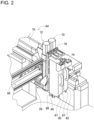
- a work machine described in Patent Literature 1 attaches a wire member supplied from a wire member transfer device to a wire member conveyance and insertion device to a printed circuit board.
- the wire member conveyance and insertion device includes a pair of chucks.
- the pair of chucks hold corresponding end portions of the wire member and move the wire member in up-down direction while holding the relevant end portions.
- the pair of chucks insert subsequently the corresponding end portions of the wire member into insertion holes in a printed circuit board from thereabove.
- Patent literature 2-4 disclose further examples of related art.
- the pair of chucks are individually moved upwards and downwards by rotating a head rotor with the wire member conveyance and insertion device fixed in position.
- the other of the pair of chucks is caused to descend to perform its inserting operation.
- the end portions of the wire member are inserted individually into the two corresponding insertion holes lying adjacent to each other.
- the disclosure has been made in view of the problem described above, and an object of the disclosure is to provide a work machine and a mounting method by which end portions of a wire member can be mounted on connecting sections that are arranged variously.
- the work head is moved after the first end portion has been mounted on the first connecting section.
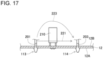
- the moving section moves the work head in accordance with the position of the second connecting section, enabling the position of the second holding section and the position of the second connecting section, that is, the position of the second end portion and the position of the second connecting section to be aligned.
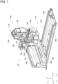
- component supply device 30 is provided at a front end of frame section 40 in front-rear direction thereof.
- Component supply device 30 includes, for example, tray-type component supply device 97 and a feeder-type component supply device (whose illustration is omitted).
- Tray-type component supply device 97 constitutes a device configured to supply components resting on a tray.
- the feeder-type component supply device constitutes a device configured to supply components (lead components or the like) using a tape feeder (whose illustration is omitted) or a stick feeder (whose illustration is omitted).
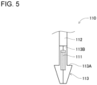
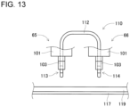
- component mounter 10 may automatically dispose chucks 65, 66 based on the positions or the like so detected. In this case, even when multiple jumper wires 110 are disposed at different intervals W1, component mounter 10 can automatically detect interval W1 so as to pick up jumper wire 110 using chucks 65, 66. In other words, jumper wires 110 can easily be disposed on holding member 119.
- Components supplied by component supply device 30 and bulk component supply device 32 include, in addition to jumper wires 110, electronic circuit components, solar cell components, power module components, and the like.
- Electronic circuit components include a lead component having a lead wire (a radial component, an axial component, or the like) or a component having no lead wire.
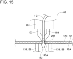
- controller 190 causes second end portion 114 to be mounted in through hole 203 (refer to Fig. 16 ) after having moved work head 60 in S15 (S17). Controller 190 controls work head 60 as in S13, causing chuck 66 to install second end portion 114 in an interior of through hole 203. As a result, jumper wire 110 can be mounted on circuit substrate 12.
Landscapes
- Engineering & Computer Science (AREA)
- Manufacturing & Machinery (AREA)
- Microelectronics & Electronic Packaging (AREA)
- Operations Research (AREA)
- Automation & Control Theory (AREA)
- Supply And Installment Of Electrical Components (AREA)
Claims (4)
- Machine de travail (10) comprenant :un dispositif de maintien de substrat (52) configuré pour maintenir un substrat de circuit (12), le substrat de circuit (12) incluant une première section de connexion (201) et une deuxième section de connexion (203) ;une tête de travail (60, 62) configurée pour tenir un élément de fil (110) incluant une première partie d'extrémité (113) et une deuxième partie d'extrémité (114) de manière à monter l'élément de fil (110) sur le substrat de circuit (12) tenu par le dispositif de maintien de substrat (52), la tête de travail (60, 62) comprenant une première section de maintien (65) configurée pour maintenir la première partie d'extrémité (113) et une deuxième section de maintien (66) configurée pour tenir la deuxième partie d'extrémité (114) ;un dispositif d'alimentation (97) configuré pour fournir l'élément de fil (110) à la tête de travail (60, 62), la tête de travail (60, 62) étant configurée pour saisir l'élément de fil (110) fourni en attrapant la première partie d'extrémité (113) de l'élément de fil (110) avec la première section de maintien (65) et la deuxième partie d'extrémité (114) de l'élément de fil (110) avec la deuxième section de maintien (66) ; etun dispositif de commande (190) comprenant :une première section de montage (261) configurée pour monter la première partie d'extrémité (113), maintenue par la première section de maintien (65), sur la première section de connexion (201) ; etune deuxième section de montage (265) configurée pour monter la deuxième partie d'extrémité (114), maintenue par la deuxième section de maintien (66), sur la deuxième section de connexion (203),caractérisé en ce queun dispositif de déplacement de la tête de travail (64) configuré pour déplacer la tête de travail (60, 62) dans une direction X et une direction Y dans un plan horizontal et dans une direction Z verticale ; etun dispositif d'imagerie (28, 67) configuré pour prendre une image de la tête de travail (60, 62) maintenant l'élément de fil (110), dans lequel le dispositif d'imagerie (28, 67) prend une image de la tête de travail (60, 62) après que l'élément de fil (110) a été fourni par le dispositif d'alimentation (97) à la tête de travail (60, 62) ;et en ce que le dispositif de commande (190) comprend en outre :une section de déplacement (263) configurée pour amener le dispositif de déplacement de la tête de travail (64) à déplacer la tête de travail (60, 62) dans la direction X et la direction Y dans le plan horizontal en fonction d'une position de la deuxième section de connexion (203) après avoir monté la première partie d'extrémité (113) sur la première section de connexion (201) ; etune section de détermination (267) configurée pour déterminer si la première partie d'extrémité (113) et la deuxième partie d'extrémité (114) de l'élément de fil (110) sont correctement prises par la première section de maintien (65) et la deuxième section de maintien (66) sur la base des données d'image obtenues par le dispositif d'imagerie (28, 67).
- Machine de travail (10) selon la revendication 1, dans lequel dans le cas où un composant (210 - 213) monté sur le substrat du circuit (12) se trouve entre la première section de connexion (201) et la deuxième section de connexion (203), la section de déplacement (263) est configurée pour déplacer la tête de travail (60, 62) en fonction d'une position du composant (210 - 213) de manière à disposer de l'élément de fil (110) en évitant le composant (210 - 213).
- Machine de travail (10) selon l'une quelconque des revendications 1 à 2,dans lequel le substrat de circuit (12) a une forme de plaque plate et inclut une première surface (12B) et une deuxième surface (12A) qui fait face à la première surface (12B), etdans lequel la machine de travail (10) comprend en outre :
un dispositif de support de substrat (33) configuré pour supporter le substrat de circuit (12) à partir de la deuxième surface (12A) dans au moins l'un des cas suivants : la première partie d'extrémité (113) de l'élément de fil (110) disposé sur la première surface (12B) est montée dans la première section de connexion (201) et la deuxième partie d'extrémité (114) de l'élément de fil (110) disposé sur la première surface (12B) est montée dans la deuxième section de connexion (203). - Procédé de montage pour une machine de travail (10) comprenant un dispositif de maintien de substrat (52) configuré pour maintenir un substrat de circuit (12) comprenant une première section de connexion (201) et une deuxième section de connexion (203), une tête de travail (60, 62) configurée pour maintenir un élément de fil (110) comprenant une première partie d'extrémité (113) et une deuxième partie d'extrémité (114) de manière à monter l'élément de fil (110) sur le substrat de circuit (12) maintenu par le dispositif de maintien de substrat (52), la tête de travail (60, 62) comprenant une première section de maintien (65) configurée pour maintenir la première partie d'extrémité (113) et une deuxième section de maintien (66) configurée pour maintenir la deuxième partie d'extrémité (114), et un dispositif de déplacement de la tête de travail (64) configuré pour déplacer la tête de travail (60, 62) dans une direction X et une direction Y dans un plan horizontal et dans une direction Z verticale, et un dispositif d'alimentation (97) configuré pour fournir l'élément de fil (110) à la tête de travail (60, 62), le procédé de montage étant configurée pour monter l'élément de fil (110) sur le substrat de circuit (12),le procédé de montage comprenant :une étape de fourniture de l'élément de fil (110)une étape au cours de laquelle la tête de travail (60, 62) saisit l'élément de fil fourni (110) en attrapant la première partie d'extrémité (113) de l'élément de fil (110) avec la première section de maintien (65) et la deuxième partie d'extrémité (114) de l'élément de fil (110) avec la deuxième section de maintien (66) ;une première étape de montage (S13) de montage de la première partie d'extrémité (113) maintenue par la première section de maintien (65) sur la première section de connexion (201) ; etune deuxième étape de montage (S17) de montage de la deuxième partie d'extrémité (114) maintenue par la deuxième section de maintien (66) sur la deuxième section de connexion (203),caractérisé en ce queune étape d'imagerie de la tête de travail (60, 62) maintenant l'élément de fil (110) après que l'élément de fil (110) a été fourni par le dispositif d'alimentation (97) à la tête de travail (60, 62) ;une étape de détermination (S9) de détermination du fait que la première partie d'extrémité (113) et la deuxième partie d'extrémité (114) de l'élément de fil (110) sont correctement prises par la première section de maintien (65) et la deuxième section de maintien (66) sur la base des données d'image obtenues par le dispositif d'imagerie (28, 67), etune étape de déplacement (S15) amenant le dispositif de déplacement de la tête de travail (64) à déplacer la tête de travail (60, 62) dans une direction X et/ou une direction Y dans un plan horizontal en fonction d'une position de la deuxième section de connexion (203) après que la première partie d'extrémité (113) a été montée sur la première section de connexion (201).
Applications Claiming Priority (1)
| Application Number | Priority Date | Filing Date | Title |
|---|---|---|---|
| PCT/JP2017/040973 WO2019097585A1 (fr) | 2017-11-14 | 2017-11-14 | Machine de travail et procédé de montage |
Publications (3)
| Publication Number | Publication Date |
|---|---|
| EP3713385A1 EP3713385A1 (fr) | 2020-09-23 |
| EP3713385A4 EP3713385A4 (fr) | 2020-11-04 |
| EP3713385B1 true EP3713385B1 (fr) | 2024-07-03 |
Family
ID=66538537
Family Applications (1)
| Application Number | Title | Priority Date | Filing Date |
|---|---|---|---|
| EP17932091.6A Active EP3713385B1 (fr) | 2017-11-14 | 2017-11-14 | Machine de travail et procédé de montage |
Country Status (5)
| Country | Link |
|---|---|
| US (1) | US11272647B2 (fr) |
| EP (1) | EP3713385B1 (fr) |
| JP (1) | JP6967605B2 (fr) |
| CN (1) | CN111512713B (fr) |
| WO (1) | WO2019097585A1 (fr) |
Family Cites Families (15)
| Publication number | Priority date | Publication date | Assignee | Title |
|---|---|---|---|---|
| JPS59172300A (ja) * | 1983-03-18 | 1984-09-28 | 松下電工株式会社 | リ−ド線の実装方法 |
| JPS60249400A (ja) * | 1984-09-28 | 1985-12-10 | パイオニア株式会社 | ジヤンパ−線自動插入機 |
| JPS61288500A (ja) * | 1985-06-17 | 1986-12-18 | 富士通株式会社 | ワイヤボンデイング作業方法 |
| JPS62119352A (ja) | 1985-11-18 | 1987-05-30 | Matsushita Electric Ind Co Ltd | 空気調和機の水受装置 |
| JPS62119352U (fr) | 1986-01-23 | 1987-07-29 | ||
| JPS62173041A (ja) * | 1986-01-23 | 1987-07-29 | Pioneer Electronic Corp | 線材切断装置 |
| JPH09205297A (ja) * | 1996-01-26 | 1997-08-05 | Matsushita Electric Ind Co Ltd | 電子部品実装方法 |
| JP4413411B2 (ja) * | 2000-10-16 | 2010-02-10 | パナソニック株式会社 | 部品挿入装置及び部品挿入方法 |
| JP3661655B2 (ja) * | 2002-02-27 | 2005-06-15 | 株式会社デンソー | 回転電機のブラシ組体の組付けに用いるブラシサポート治具及びそれを用いたブラシ組体の組付け方法 |
| US20040108130A1 (en) * | 2002-12-09 | 2004-06-10 | Yazaki Corporation | Mounting structure for electronic component |
| WO2014045370A1 (fr) * | 2012-09-20 | 2014-03-27 | 富士機械製造株式会社 | Machine de travail pour cartes à circuits imprimés et procédé de montage |
| WO2014207802A1 (fr) * | 2013-06-24 | 2014-12-31 | 富士機械製造株式会社 | Machine de montage de composants |
| CN203435239U (zh) * | 2013-09-16 | 2014-02-12 | 纬创资通股份有限公司 | 插线装置 |
| JP6019410B2 (ja) * | 2013-11-13 | 2016-11-02 | パナソニックIpマネジメント株式会社 | 電子部品実装装置及び電子部品実装方法 |
| JP2017010953A (ja) * | 2015-06-16 | 2017-01-12 | 富士電機株式会社 | リード線処理装置 |
-
2017
- 2017-11-14 US US16/758,963 patent/US11272647B2/en active Active
- 2017-11-14 CN CN201780096599.5A patent/CN111512713B/zh active Active
- 2017-11-14 EP EP17932091.6A patent/EP3713385B1/fr active Active
- 2017-11-14 JP JP2019554079A patent/JP6967605B2/ja active Active
- 2017-11-14 WO PCT/JP2017/040973 patent/WO2019097585A1/fr not_active Ceased
Also Published As
| Publication number | Publication date |
|---|---|
| WO2019097585A1 (fr) | 2019-05-23 |
| EP3713385A4 (fr) | 2020-11-04 |
| US20200352066A1 (en) | 2020-11-05 |
| CN111512713B (zh) | 2021-06-04 |
| US11272647B2 (en) | 2022-03-08 |
| CN111512713A (zh) | 2020-08-07 |
| JPWO2019097585A1 (ja) | 2020-10-22 |
| EP3713385A1 (fr) | 2020-09-23 |
| JP6967605B2 (ja) | 2021-11-17 |
Similar Documents
| Publication | Publication Date | Title |
|---|---|---|
| JP6619019B2 (ja) | 対基板作業システム、および挿入方法 | |
| EP3379912B1 (fr) | Machine de travail sur substrat et procédé d'insertion | |
| CN108029231B (zh) | 对基板作业机及识别方法 | |
| EP3310146B1 (fr) | Machine d'usinage de substrat et procédé de reconnaissance | |
| WO2017060974A1 (fr) | Dispositif de découpe/pliage et dispositif de découpe | |
| JP6851227B2 (ja) | 対基板作業機 | |
| EP3713385B1 (fr) | Machine de travail et procédé de montage | |
| JP7010980B2 (ja) | 切断・屈曲方法 | |
| EP3379911B1 (fr) | Machine de travail sur substrats et procédé d'insertion | |
| CN114554830A (zh) | 作业机及安装方法 | |
| EP3500081B1 (fr) | Machine d'usinage de substrat | |
| JP7179992B2 (ja) | 対基板作業機と対基板作業機の制御方法 | |
| JP2022036251A (ja) | 切断・屈曲装置、および屈曲装置 | |
| JP6858273B2 (ja) | 作業機、装着方法 | |
| EP4123689B1 (fr) | Machine de travail de substrat | |
| WO2021044506A1 (fr) | Machine de travail et procédé de montage de composant |
Legal Events
| Date | Code | Title | Description |
|---|---|---|---|
| STAA | Information on the status of an ep patent application or granted ep patent |
Free format text: STATUS: THE INTERNATIONAL PUBLICATION HAS BEEN MADE |
|
| PUAI | Public reference made under article 153(3) epc to a published international application that has entered the european phase |
Free format text: ORIGINAL CODE: 0009012 |
|
| STAA | Information on the status of an ep patent application or granted ep patent |
Free format text: STATUS: REQUEST FOR EXAMINATION WAS MADE |
|
| 17P | Request for examination filed |
Effective date: 20200429 |
|
| AK | Designated contracting states |
Kind code of ref document: A1 Designated state(s): AL AT BE BG CH CY CZ DE DK EE ES FI FR GB GR HR HU IE IS IT LI LT LU LV MC MK MT NL NO PL PT RO RS SE SI SK SM TR |
|
| AX | Request for extension of the european patent |
Extension state: BA ME |
|
| A4 | Supplementary search report drawn up and despatched |
Effective date: 20201002 |
|
| RIC1 | Information provided on ipc code assigned before grant |
Ipc: H05K 13/08 20060101ALI20200928BHEP Ipc: H05K 13/04 20060101AFI20200928BHEP Ipc: H05K 13/06 20060101ALI20200928BHEP |
|
| DAV | Request for validation of the european patent (deleted) | ||
| DAX | Request for extension of the european patent (deleted) | ||
| STAA | Information on the status of an ep patent application or granted ep patent |
Free format text: STATUS: EXAMINATION IS IN PROGRESS |
|
| 17Q | First examination report despatched |
Effective date: 20220610 |
|
| P01 | Opt-out of the competence of the unified patent court (upc) registered |
Effective date: 20230328 |
|
| GRAP | Despatch of communication of intention to grant a patent |
Free format text: ORIGINAL CODE: EPIDOSNIGR1 |
|
| STAA | Information on the status of an ep patent application or granted ep patent |
Free format text: STATUS: GRANT OF PATENT IS INTENDED |
|
| INTG | Intention to grant announced |
Effective date: 20240320 |
|
| GRAS | Grant fee paid |
Free format text: ORIGINAL CODE: EPIDOSNIGR3 |
|
| GRAA | (expected) grant |
Free format text: ORIGINAL CODE: 0009210 |
|
| STAA | Information on the status of an ep patent application or granted ep patent |
Free format text: STATUS: THE PATENT HAS BEEN GRANTED |
|
| AK | Designated contracting states |
Kind code of ref document: B1 Designated state(s): AL AT BE BG CH CY CZ DE DK EE ES FI FR GB GR HR HU IE IS IT LI LT LU LV MC MK MT NL NO PL PT RO RS SE SI SK SM TR |
|
| REG | Reference to a national code |
Ref country code: CH Ref legal event code: EP |
|
| REG | Reference to a national code |
Ref country code: DE Ref legal event code: R096 Ref document number: 602017083115 Country of ref document: DE |
|
| REG | Reference to a national code |
Ref country code: LT Ref legal event code: MG9D |
|
| REG | Reference to a national code |
Ref country code: NL Ref legal event code: MP Effective date: 20240703 |
|
| PG25 | Lapsed in a contracting state [announced via postgrant information from national office to epo] |
Ref country code: PT Free format text: LAPSE BECAUSE OF FAILURE TO SUBMIT A TRANSLATION OF THE DESCRIPTION OR TO PAY THE FEE WITHIN THE PRESCRIBED TIME-LIMIT Effective date: 20241104 |
|
| REG | Reference to a national code |
Ref country code: AT Ref legal event code: MK05 Ref document number: 1701137 Country of ref document: AT Kind code of ref document: T Effective date: 20240703 |
|
| PG25 | Lapsed in a contracting state [announced via postgrant information from national office to epo] |
Ref country code: NL Free format text: LAPSE BECAUSE OF FAILURE TO SUBMIT A TRANSLATION OF THE DESCRIPTION OR TO PAY THE FEE WITHIN THE PRESCRIBED TIME-LIMIT Effective date: 20240703 |
|
| PG25 | Lapsed in a contracting state [announced via postgrant information from national office to epo] |
Ref country code: PT Free format text: LAPSE BECAUSE OF FAILURE TO SUBMIT A TRANSLATION OF THE DESCRIPTION OR TO PAY THE FEE WITHIN THE PRESCRIBED TIME-LIMIT Effective date: 20241104 Ref country code: NL Free format text: LAPSE BECAUSE OF FAILURE TO SUBMIT A TRANSLATION OF THE DESCRIPTION OR TO PAY THE FEE WITHIN THE PRESCRIBED TIME-LIMIT Effective date: 20240703 |
|
| PG25 | Lapsed in a contracting state [announced via postgrant information from national office to epo] |
Ref country code: NO Free format text: LAPSE BECAUSE OF FAILURE TO SUBMIT A TRANSLATION OF THE DESCRIPTION OR TO PAY THE FEE WITHIN THE PRESCRIBED TIME-LIMIT Effective date: 20241003 |
|
| PG25 | Lapsed in a contracting state [announced via postgrant information from national office to epo] |
Ref country code: FI Free format text: LAPSE BECAUSE OF FAILURE TO SUBMIT A TRANSLATION OF THE DESCRIPTION OR TO PAY THE FEE WITHIN THE PRESCRIBED TIME-LIMIT Effective date: 20240703 Ref country code: GR Free format text: LAPSE BECAUSE OF FAILURE TO SUBMIT A TRANSLATION OF THE DESCRIPTION OR TO PAY THE FEE WITHIN THE PRESCRIBED TIME-LIMIT Effective date: 20241004 Ref country code: PL Free format text: LAPSE BECAUSE OF FAILURE TO SUBMIT A TRANSLATION OF THE DESCRIPTION OR TO PAY THE FEE WITHIN THE PRESCRIBED TIME-LIMIT Effective date: 20240703 |
|
| PG25 | Lapsed in a contracting state [announced via postgrant information from national office to epo] |
Ref country code: BG Free format text: LAPSE BECAUSE OF FAILURE TO SUBMIT A TRANSLATION OF THE DESCRIPTION OR TO PAY THE FEE WITHIN THE PRESCRIBED TIME-LIMIT Effective date: 20240703 |
|
| PG25 | Lapsed in a contracting state [announced via postgrant information from national office to epo] |
Ref country code: LV Free format text: LAPSE BECAUSE OF FAILURE TO SUBMIT A TRANSLATION OF THE DESCRIPTION OR TO PAY THE FEE WITHIN THE PRESCRIBED TIME-LIMIT Effective date: 20240703 |
|
| PG25 | Lapsed in a contracting state [announced via postgrant information from national office to epo] |
Ref country code: IS Free format text: LAPSE BECAUSE OF FAILURE TO SUBMIT A TRANSLATION OF THE DESCRIPTION OR TO PAY THE FEE WITHIN THE PRESCRIBED TIME-LIMIT Effective date: 20241103 Ref country code: AT Free format text: LAPSE BECAUSE OF FAILURE TO SUBMIT A TRANSLATION OF THE DESCRIPTION OR TO PAY THE FEE WITHIN THE PRESCRIBED TIME-LIMIT Effective date: 20240703 |
|
| PG25 | Lapsed in a contracting state [announced via postgrant information from national office to epo] |
Ref country code: HR Free format text: LAPSE BECAUSE OF FAILURE TO SUBMIT A TRANSLATION OF THE DESCRIPTION OR TO PAY THE FEE WITHIN THE PRESCRIBED TIME-LIMIT Effective date: 20240703 Ref country code: CZ Free format text: LAPSE BECAUSE OF FAILURE TO SUBMIT A TRANSLATION OF THE DESCRIPTION OR TO PAY THE FEE WITHIN THE PRESCRIBED TIME-LIMIT Effective date: 20240703 |
|
| PG25 | Lapsed in a contracting state [announced via postgrant information from national office to epo] |
Ref country code: RS Free format text: LAPSE BECAUSE OF FAILURE TO SUBMIT A TRANSLATION OF THE DESCRIPTION OR TO PAY THE FEE WITHIN THE PRESCRIBED TIME-LIMIT Effective date: 20241003 Ref country code: ES Free format text: LAPSE BECAUSE OF FAILURE TO SUBMIT A TRANSLATION OF THE DESCRIPTION OR TO PAY THE FEE WITHIN THE PRESCRIBED TIME-LIMIT Effective date: 20240703 |
|
| PG25 | Lapsed in a contracting state [announced via postgrant information from national office to epo] |
Ref country code: RS Free format text: LAPSE BECAUSE OF FAILURE TO SUBMIT A TRANSLATION OF THE DESCRIPTION OR TO PAY THE FEE WITHIN THE PRESCRIBED TIME-LIMIT Effective date: 20241003 Ref country code: PL Free format text: LAPSE BECAUSE OF FAILURE TO SUBMIT A TRANSLATION OF THE DESCRIPTION OR TO PAY THE FEE WITHIN THE PRESCRIBED TIME-LIMIT Effective date: 20240703 Ref country code: NO Free format text: LAPSE BECAUSE OF FAILURE TO SUBMIT A TRANSLATION OF THE DESCRIPTION OR TO PAY THE FEE WITHIN THE PRESCRIBED TIME-LIMIT Effective date: 20241003 Ref country code: LV Free format text: LAPSE BECAUSE OF FAILURE TO SUBMIT A TRANSLATION OF THE DESCRIPTION OR TO PAY THE FEE WITHIN THE PRESCRIBED TIME-LIMIT Effective date: 20240703 Ref country code: IS Free format text: LAPSE BECAUSE OF FAILURE TO SUBMIT A TRANSLATION OF THE DESCRIPTION OR TO PAY THE FEE WITHIN THE PRESCRIBED TIME-LIMIT Effective date: 20241103 Ref country code: HR Free format text: LAPSE BECAUSE OF FAILURE TO SUBMIT A TRANSLATION OF THE DESCRIPTION OR TO PAY THE FEE WITHIN THE PRESCRIBED TIME-LIMIT Effective date: 20240703 Ref country code: GR Free format text: LAPSE BECAUSE OF FAILURE TO SUBMIT A TRANSLATION OF THE DESCRIPTION OR TO PAY THE FEE WITHIN THE PRESCRIBED TIME-LIMIT Effective date: 20241004 Ref country code: FI Free format text: LAPSE BECAUSE OF FAILURE TO SUBMIT A TRANSLATION OF THE DESCRIPTION OR TO PAY THE FEE WITHIN THE PRESCRIBED TIME-LIMIT Effective date: 20240703 Ref country code: ES Free format text: LAPSE BECAUSE OF FAILURE TO SUBMIT A TRANSLATION OF THE DESCRIPTION OR TO PAY THE FEE WITHIN THE PRESCRIBED TIME-LIMIT Effective date: 20240703 Ref country code: CZ Free format text: LAPSE BECAUSE OF FAILURE TO SUBMIT A TRANSLATION OF THE DESCRIPTION OR TO PAY THE FEE WITHIN THE PRESCRIBED TIME-LIMIT Effective date: 20240703 Ref country code: BG Free format text: LAPSE BECAUSE OF FAILURE TO SUBMIT A TRANSLATION OF THE DESCRIPTION OR TO PAY THE FEE WITHIN THE PRESCRIBED TIME-LIMIT Effective date: 20240703 Ref country code: AT Free format text: LAPSE BECAUSE OF FAILURE TO SUBMIT A TRANSLATION OF THE DESCRIPTION OR TO PAY THE FEE WITHIN THE PRESCRIBED TIME-LIMIT Effective date: 20240703 |
|
| REG | Reference to a national code |
Ref country code: DE Ref legal event code: R097 Ref document number: 602017083115 Country of ref document: DE |
|
| PG25 | Lapsed in a contracting state [announced via postgrant information from national office to epo] |
Ref country code: SM Free format text: LAPSE BECAUSE OF FAILURE TO SUBMIT A TRANSLATION OF THE DESCRIPTION OR TO PAY THE FEE WITHIN THE PRESCRIBED TIME-LIMIT Effective date: 20240703 Ref country code: DK Free format text: LAPSE BECAUSE OF FAILURE TO SUBMIT A TRANSLATION OF THE DESCRIPTION OR TO PAY THE FEE WITHIN THE PRESCRIBED TIME-LIMIT Effective date: 20240703 Ref country code: RO Free format text: LAPSE BECAUSE OF FAILURE TO SUBMIT A TRANSLATION OF THE DESCRIPTION OR TO PAY THE FEE WITHIN THE PRESCRIBED TIME-LIMIT Effective date: 20240703 |
|
| PG25 | Lapsed in a contracting state [announced via postgrant information from national office to epo] |
Ref country code: EE Free format text: LAPSE BECAUSE OF FAILURE TO SUBMIT A TRANSLATION OF THE DESCRIPTION OR TO PAY THE FEE WITHIN THE PRESCRIBED TIME-LIMIT Effective date: 20240703 |
|
| PG25 | Lapsed in a contracting state [announced via postgrant information from national office to epo] |
Ref country code: IT Free format text: LAPSE BECAUSE OF FAILURE TO SUBMIT A TRANSLATION OF THE DESCRIPTION OR TO PAY THE FEE WITHIN THE PRESCRIBED TIME-LIMIT Effective date: 20240703 Ref country code: SK Free format text: LAPSE BECAUSE OF FAILURE TO SUBMIT A TRANSLATION OF THE DESCRIPTION OR TO PAY THE FEE WITHIN THE PRESCRIBED TIME-LIMIT Effective date: 20240703 |
|
| PLBE | No opposition filed within time limit |
Free format text: ORIGINAL CODE: 0009261 |
|
| STAA | Information on the status of an ep patent application or granted ep patent |
Free format text: STATUS: NO OPPOSITION FILED WITHIN TIME LIMIT |
|
| 26N | No opposition filed |
Effective date: 20250404 |
|
| REG | Reference to a national code |
Ref country code: CH Ref legal event code: PL |
|
| PG25 | Lapsed in a contracting state [announced via postgrant information from national office to epo] |
Ref country code: MC Free format text: LAPSE BECAUSE OF FAILURE TO SUBMIT A TRANSLATION OF THE DESCRIPTION OR TO PAY THE FEE WITHIN THE PRESCRIBED TIME-LIMIT Effective date: 20240703 |
|
| PG25 | Lapsed in a contracting state [announced via postgrant information from national office to epo] |
Ref country code: LU Free format text: LAPSE BECAUSE OF NON-PAYMENT OF DUE FEES Effective date: 20241114 |
|
| REG | Reference to a national code |
Ref country code: CH Ref legal event code: PL |
|
| GBPC | Gb: european patent ceased through non-payment of renewal fee |
Effective date: 20241114 |
|
| PG25 | Lapsed in a contracting state [announced via postgrant information from national office to epo] |
Ref country code: CH Free format text: LAPSE BECAUSE OF NON-PAYMENT OF DUE FEES Effective date: 20241130 |
|
| REG | Reference to a national code |
Ref country code: BE Ref legal event code: MM Effective date: 20241130 |
|
| PG25 | Lapsed in a contracting state [announced via postgrant information from national office to epo] |
Ref country code: SE Free format text: LAPSE BECAUSE OF FAILURE TO SUBMIT A TRANSLATION OF THE DESCRIPTION OR TO PAY THE FEE WITHIN THE PRESCRIBED TIME-LIMIT Effective date: 20240703 |
|
| PG25 | Lapsed in a contracting state [announced via postgrant information from national office to epo] |
Ref country code: GB Free format text: LAPSE BECAUSE OF NON-PAYMENT OF DUE FEES Effective date: 20241114 Ref country code: BE Free format text: LAPSE BECAUSE OF NON-PAYMENT OF DUE FEES Effective date: 20241130 |
|
| PG25 | Lapsed in a contracting state [announced via postgrant information from national office to epo] |
Ref country code: FR Free format text: LAPSE BECAUSE OF NON-PAYMENT OF DUE FEES Effective date: 20241130 |
|
| PG25 | Lapsed in a contracting state [announced via postgrant information from national office to epo] |
Ref country code: IE Free format text: LAPSE BECAUSE OF NON-PAYMENT OF DUE FEES Effective date: 20241114 |
|
| PGFP | Annual fee paid to national office [announced via postgrant information from national office to epo] |
Ref country code: DE Payment date: 20250930 Year of fee payment: 9 |
|
| PG25 | Lapsed in a contracting state [announced via postgrant information from national office to epo] |
Ref country code: HU Free format text: LAPSE BECAUSE OF FAILURE TO SUBMIT A TRANSLATION OF THE DESCRIPTION OR TO PAY THE FEE WITHIN THE PRESCRIBED TIME-LIMIT; INVALID AB INITIO Effective date: 20171114 |
|
| PG25 | Lapsed in a contracting state [announced via postgrant information from national office to epo] |
Ref country code: CY Free format text: LAPSE BECAUSE OF FAILURE TO SUBMIT A TRANSLATION OF THE DESCRIPTION OR TO PAY THE FEE WITHIN THE PRESCRIBED TIME-LIMIT; INVALID AB INITIO Effective date: 20171114 |