EP3714089B1 - Article tricoté et procédé pour son obtention - Google Patents
Article tricoté et procédé pour son obtention Download PDFInfo
- Publication number
- EP3714089B1 EP3714089B1 EP18807255.7A EP18807255A EP3714089B1 EP 3714089 B1 EP3714089 B1 EP 3714089B1 EP 18807255 A EP18807255 A EP 18807255A EP 3714089 B1 EP3714089 B1 EP 3714089B1
- Authority
- EP
- European Patent Office
- Prior art keywords
- knitted
- layer
- coupling
- thread
- knitting
- Prior art date
- Legal status (The legal status is an assumption and is not a legal conclusion. Google has not performed a legal analysis and makes no representation as to the accuracy of the status listed.)
- Active
Links
Images




Classifications
-
- D—TEXTILES; PAPER
- D04—BRAIDING; LACE-MAKING; KNITTING; TRIMMINGS; NON-WOVEN FABRICS
- D04B—KNITTING
- D04B1/00—Weft knitting processes for the production of fabrics or articles not dependent on the use of particular machines; Fabrics or articles defined by such processes
- D04B1/10—Patterned fabrics or articles
- D04B1/12—Patterned fabrics or articles characterised by thread material
-
- D—TEXTILES; PAPER
- D04—BRAIDING; LACE-MAKING; KNITTING; TRIMMINGS; NON-WOVEN FABRICS
- D04B—KNITTING
- D04B1/00—Weft knitting processes for the production of fabrics or articles not dependent on the use of particular machines; Fabrics or articles defined by such processes
- D04B1/22—Weft knitting processes for the production of fabrics or articles not dependent on the use of particular machines; Fabrics or articles defined by such processes specially adapted for knitting goods of particular configuration
-
- D—TEXTILES; PAPER
- D04—BRAIDING; LACE-MAKING; KNITTING; TRIMMINGS; NON-WOVEN FABRICS
- D04B—KNITTING
- D04B1/00—Weft knitting processes for the production of fabrics or articles not dependent on the use of particular machines; Fabrics or articles defined by such processes
- D04B1/22—Weft knitting processes for the production of fabrics or articles not dependent on the use of particular machines; Fabrics or articles defined by such processes specially adapted for knitting goods of particular configuration
- D04B1/24—Weft knitting processes for the production of fabrics or articles not dependent on the use of particular machines; Fabrics or articles defined by such processes specially adapted for knitting goods of particular configuration wearing apparel
- D04B1/28—Weft knitting processes for the production of fabrics or articles not dependent on the use of particular machines; Fabrics or articles defined by such processes specially adapted for knitting goods of particular configuration wearing apparel gloves
-
- D—TEXTILES; PAPER
- D10—INDEXING SCHEME ASSOCIATED WITH SUBLASSES OF SECTION D, RELATING TO TEXTILES
- D10B—INDEXING SCHEME ASSOCIATED WITH SUBLASSES OF SECTION D, RELATING TO TEXTILES
- D10B2403/00—Details of fabric structure established in the fabric forming process
- D10B2403/02—Cross-sectional features
- D10B2403/023—Fabric with at least two, predominantly unlinked, knitted or woven plies interlaced with each other at spaced locations or linked to a common internal co-extensive yarn system
-
- D—TEXTILES; PAPER
- D10—INDEXING SCHEME ASSOCIATED WITH SUBLASSES OF SECTION D, RELATING TO TEXTILES
- D10B—INDEXING SCHEME ASSOCIATED WITH SUBLASSES OF SECTION D, RELATING TO TEXTILES
- D10B2403/00—Details of fabric structure established in the fabric forming process
- D10B2403/02—Cross-sectional features
- D10B2403/024—Fabric incorporating additional compounds
- D10B2403/0243—Fabric incorporating additional compounds enhancing functional properties
- D10B2403/02431—Fabric incorporating additional compounds enhancing functional properties with electronic components, e.g. sensors or switches
Definitions
- the invention relates to the field of sensors integrated in textiles.
- Sensors integrated in textile materials are known.
- EN 10 2016 10 60 71 A1 a fabric with at least three layers arranged one above the other, at least two of which are designed as fabric layers.
- the fabric layers form a sandwich arrangement with a middle layer.
- the middle layer can also be a fabric layer or another layer made of nonwoven material, foam material, knitted fabric, etc.
- the first and second fabric layers contain electrically conductive warp threads or weft threads and thus form electrode areas.
- the middle layer provides an electrical coupling between these electrodes. This coupling can be used to form, for example, a capacitive, resistive or piezoresistive sensor arrangement.
- WO 2014/160764 A1 describes a piece of clothing with a sensor for monitoring a body function.
- the sensor can be a separate sensor that is placed in a pocket or a cuff of the piece of clothing.
- the sensor can have one or more knitted layers.
- the sensor can be designed as a capacitive sensor and determine the capacitance between a first layer and a third layer.
- the sensor can alternatively be a piezoelectric sensor in which a knitted sensor layer is arranged between two non-conductive plates.
- a piezoresistive sensor can also be used as a sensor in which a piezoresistive semiconductor polymer is arranged between two conductive threads of adjacent layers.
- WO 2004/100784 A2 discloses knitted transducer devices. Elastically stretchable structures are formed in a transducer zone so that their electrical properties can be changed by deforming the transducer zone. In a piece of clothing, several separate knitted fabrics can be arranged one above the other. This can be used to form a capacitive sensor, for example.
- the invention provides for creating a knitted product in which a functional section is present.
- the functional section can provide a sensor function.
- the knitted product can thus also be referred to as a sensory knitted product.
- the knitted product can be, for example, a medical product and/or an item of clothing, such as a bandage, a compression stocking or support stocking, a glove, a sock, a stocking, an outer garment, an inner garment, etc., or at least form a significant part thereof.
- the coupling layer is designed as a knitted layer and in particular as a middle knitted layer. If the functional section is integrated in a knitted product that also has several knitted layers, such as closed, tubular or pocket-shaped areas of the knitted product, one or more further knitted layers are optionally added to the knitted layers within the functional section. All knitted layers are produced using a knitting machine during the manufacture of the knitted product and are connected to one another during and by knitting. Within the functional section there are in particular no knitted layers that have to be connected to one another separately after knitting by sewing, gluing or another additional type of connection. The knitted layers present in the functional section are connected to one another at least at the edge or outside the functional section and also within the functional section by connecting knitting stitches. Subsequent connection is therefore not necessary. The individual knitted layers are connected by and during knitting of the knitted product.
- an electrically conductive first electrode region and an electrically conductive second electrode region are formed in the first and/or second knitting layer by knitting with an electrically conductive thread.
- the two electrode regions are not directly electrically connected to one another within the functional section and therefore not short-circuited.
- the two electrode regions within the functional section are coupled by a coupling region.
- the coupling region can be designed either in an additional coupling layer, which is designed as a middle knitted layer, or as a knitted region within the first or second knitted layer.
- the coupling region lies on both the first electrode region and the second electrode region or can come into contact with the electrode regions.
- the coupling region is designed to change an electrical coupling between the two electrode regions depending on an external influence.
- the electrical coupling of the electrode regions by means of the coupling region is achieved by an electrically conductive connection with variable resistance or variable conductivity, optionally additionally by a capacitive coupling, by a piezoelectric coupling or by another electrical and/or electromechanical coupling or a combination thereof.
- the functional section can be used as a sensor, for example, and form a sensory functional section.
- the sensor can be used, for example, to detect an external influence, such as an acting force or pressure, a touch or approach to an object, or the like.
- the sensor can be digital or switched, so that it only detects whether a force or pressure is acting on the functional section, or whether the functional section is in contact with an object.
- the sensor can also be designed to measure, so that the amount of an acting force or an acting pressure can be determined based on the signals provided by the sensor.
- An electrical quantity between the two electrode areas such as an electrical voltage and/or an electrical current or their change, can be monitored and/or evaluated as a sensor signal.
- an actuator functional area can also be present, which, for example, has a coupling area that works as a piezoelectric actuator when an electrical voltage, in particular alternating voltage, is applied to the electrode areas.
- the functional section By making the functional section with at least two knitted layers, the functional section is elastically stretchable. This makes the knitted product particularly suitable as an item of clothing or as an essential part of such an item of clothing. For example, a sensory glove can be made with the knitted product.
- the functional section does not affect the wearing comfort or the usual handling of the knitted product, or only affects it insignificantly. Nevertheless, the functional section of the knitted product can be produced very easily by knitting on a knitting machine in a single knitting process without any further post-processing steps.
- both the first knitted layer and the second knitted layer contain knitting stitches made of a conventional thread or yarn without an electrically conductive function.
- a stretching load can be absorbed at least partially by the conventional threads.
- These conventional threads can be natural or synthetic fiber yarns.
- an electrically conductive thread for the electrode regions and optionally a functional thread with a property that provides the electrical coupling for the electrode regions for the coupling region can be incorporated or knitted into at least one of the knitted layers to form a stitch.
- the two electrode regions are arranged in different knitted layers.
- the first electrode region is thus arranged in the first knitted layer and the second electrode region in the second knitted layer.
- the coupling region is arranged in a separate coupling layer that is arranged between the first knitted layer and the second knitted layer and between the electrode regions.
- the coupling layer rests with opposite sides on the respectively assigned electrode region. In this way, for example, a capacitive coupling, an electrically conductive coupling with variable ohmic resistance or a piezoresistive coupling can be generated between the two electrode regions.
- the coupling layer is also preferably designed as a middle knitted layer, so that its production can be very easily integrated when knitting the knitted product.
- the middle knitted layer is connected to the first knitted layer and/or the second knitted layer by one or more connecting knitting stitches inside and/or outside the functional section.
- a non-conductive thread is used in particular to produce the connecting knitting stitches. If an electrically conductive thread is used to produce the connecting knitting stitches, it must be ensured that this does not create direct contact or a short circuit between the two electrode areas. This can be achieved by appropriate spacing and/or by knitting techniques such as plating or the like.
- a thread is used when knitting the middle knitted layer, by means of which the electrical coupling between the electrode surfaces or the change in the coupling is defined when an external influence occurs, such as pressure or force.
- This thread can be referred to as a functional thread.
- the functional thread can, for example, have a changing electrical conductivity or a changing ohmic resistance, depending on an acting pressure or an acting force.
- the functional thread can also form a dielectric between the electrode surfaces, whereby the effect of pressure or force on the functional section changes the capacitance of a capacitor formed by the electrode surfaces and thus the electrical coupling.
- the two electrode regions can be arranged together in the same, for example the first knitted layer at a distance from each other.
- the coupling region is arranged in the other, for example the second knitted layer. and is in contact with or can be brought into contact with the two electrode areas in the first knitted layer. In this design, the number of layers in the functional section is reduced, which can simplify the manufacture of the knitted product.
- the electrode areas can also be manufactured using intarsia knitting. This allows the electrode areas to have any shape and at the same time be electrically separated from each other.
- the first knitted layer is connected to the second knitted layer by one or more connecting knitting stitches within the functional section or within the coupling region. This allows the required relative position of the electrode regions and the coupling region to be maintained, particularly in the case of larger functional regions.
- the connecting knitting stitches prevent the coupling from changing due to a relative displacement parallel to the plane of extension of the knitted layers, which could, for example, have a detrimental effect on the evaluation of a sensor signal generated by the functional section.
- the knitting layers can be connected using connecting stitches using a standard stitch or a catch stitch.
- the one or more connecting stitches are created by and during knitting of the first knitted layer and the second knitted layer and thus during knitting of the knitted product. Subsequent joining of the knitted layers is not necessary.
- the coupling region is produced by knitting with a functional thread.
- the functional thread has a property that defines the electrical coupling between the two electrode surfaces or the change in the electrical coupling between the two electrode surfaces.
- the property of the functional thread can be such that the electrical coupling changes due to an external influence, such as pressure or force or contact with an object.
- the functional thread can comprise dielectric material, in particular if the coupling region and the electrode regions form a capacitive sensor.
- the functional thread can also be designed to change its electrical conductivity or ohmic resistance depending on an external influence (resistive or piezoresistive property), so that an electrical connection is provided between the electrode surfaces, the resistance or conductivity of which is dependent on the external influence.
- the functional thread has piezoelectric properties and provides an electrical voltage between the electrode surfaces depending on an applied pressure or force, which can be measured.
- At least one inlay thread is inserted between the first knitted layer and the second knitted layer.
- the inlay thread itself preferably does not form any stitches with the first knitted layer and/or the second knitted layer and/or an optionally present middle knitted layer.
- the coupling layer is designed as a middle knitted layer, the at least one inlay thread can also be arranged between the first knitted layer and the middle knitted layer and/or between the second knitted layer and the middle knitted layer.
- the coupling layer can be formed, for example, by using at least one insert thread.
- a functional thread with the properties described above can therefore be used as the insert thread.
- the at least one insert thread can be used as a spacer between immediately adjacent knitted layers. This can, for example, prevent short-circuiting between the electrode areas.
- a middle knitted layer together with at least one inlay thread forms the coupling layer.
- the at least one inlay thread is thicker than the other threads used in the knitted product, in particular the stitch-forming threads. It is also possible to use different types of inlay threads, for example at least one inlay thread that belongs to or forms the coupling layer and at least one inlay thread with a spacing function between adjacent layers.
- the knitted product is preferably produced by knitting with a knitting machine and in particular a flat knitting machine.
- the knitting machine has several needle groups that can be moved independently of one another. In the knitting machine, all of the needles can also be moved or controlled individually.
- the knitting machine preferably has several separate thread guides, each of which can feed one or more threads.
- a thread guide can also be designed as a plating thread guide that feeds two threads with which a stitch can be formed at the same time.
- the first knitted layer and the second knitted layer can be knitted using one group of needles each.
- a further group of needles can be used to knit a middle knitted layer if the coupling layer is designed as a separate middle knitted layer.
- One or more further groups of needles can knit further knitted layers if the knitted product has further knitted layers in addition to the multi-layer structure in the functional section, such as in a garment, a bandage, a glove or the like, in which the knitted product is tubular and can have the functional section in a tubular area.
- the first and second knitting layers and optionally also the middle knitting layer are connected to each other by one or more connecting knitting stitches outside and inside the functional section when the knitted product is knitted. Separate gluing, sewing or other joining after the knitted product has been knitted is not necessary.
- the knitting layers are already when knitting the knitted product and by knitting the knitted product.
- the first electrode region and the second electrode region are formed using an electrically conductive thread within the functional section.
- the electrode regions can be present in the same knitting layer or in different knitting layers, as explained.
- a coupling region is created when the knitted product is knitted.
- the coupling region can be present in a coupling layer between the first knitted layer and the second knitted layer or within the first or second knitted layer.
- a functional thread is used to produce the coupling region.
- the functional thread has a property that changes the electrical coupling between the electrode regions depending on an external influence, for example depending on an applied pressure or an applied force. In this way, the knitted product can provide a sensor function in the functional section.
- the production of such a functional section and in particular a sensory functional section is simple and inexpensive.
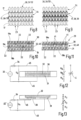
- Figure 1 a schematic partially sectioned side view a knitting machine with two needle beds
- Figure 2 and 3 each a schematic, block diagram-like representation of several machine knitting needles in a plan view to explain the knitting process on the knitting machine from Figure 1 ,
- Figures 4 to 7 different principle representations for the production and connection of individual knitting layers when knitting with a knitting machine from Figure 1 ,
- Figures 8 and 9 each a schematic diagram for knitting with different threads in a functional section of a knitted product, in particular a functional thread and/or an electrically conductive thread,
- Figures 10 and 11 each a schematic, block diagram-like side view of different layers in a functional section of a knitted product
- Figures 12 and 13 each a schematic block diagram-like representation of a first electrode region, a second electrode region and a coupling region in a functional section of a knitted product as well as electrical equivalent circuit diagrams of the coupling between the electrode regions by means of the coupling region,
- Figures 14 and 15 each a schematic sectional view through the finger of a glove with a multi-layer functional section
- Figure 16 an embodiment of a knitted product with a functional section in the form of a glove
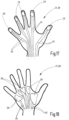
- FIGS 17 and 18 modified embodiments of the glove from Figure 16 each with several functional sections
- Figure 19 a modified embodiment of the glove with a functional section in the area of a finger joint and
- Figure 20 a schematic, block diagram-like structure of the functional section in Figure 19 in a side view.
- Figure 1 is a highly schematic and simplified illustration of a knitting machine 10, which is designed as a flat knitting machine, for example.
- the flat knitting machine has a first needle bed 11 and a second needle bed 12.
- the two needle beds are arranged on opposite sides of a working area 13.
- a plurality of machine knitting needles 14 are arranged in each needle bed 11, 12, which are guided along guide channels 15 in the respective needle bed 11 or 12 and can be moved in their longitudinal direction.
- the knitting machine 10 also has one and preferably several thread guides 16, by means of which at least one thread 17 can be fed into the working area 13 or to the machine knitting needles 14 for stitch formation.
- the thread guide 16 can be arranged above the working area 13 and transversely to the direction of extension of the machine knitting needles. 14 can be moved in a direction of movement B. It can feed a thread 17.
- the direction of movement B is in Figure 1 perpendicular to the plane of the drawing and in particular from the Figures 2 to 7
- the thread guide 16 can be moved back and forth in the direction of movement B.
- FIG 6 A design with three thread guides 16 is shown in Figure 6 presented in a highly schematic manner.
- One or more of the existing thread guides 16 can also be designed as plating thread guides and simultaneously feed two threads 17 for stitch formation.
- the machine knitting needles 14 can each be controlled individually and moved along their direction of extension in the guide channel 15.
- the sequence of a knitting process is schematically illustrated in a plan view of the knitting machine 10 or the machine knitting needles 14.
- Each machine knitting needle 14 has a hook 14a and a closing element 14b, which can be brought into contact with the tip of the hook 14a in order to close an inner hook area 14c.
- the closing element 14b is formed by a tongue in the exemplary embodiment.
- the closing element 14b could also be designed as a slider.
- FIG 3 The principle of how different knitting layers 19 can be produced is illustrated schematically.
- a needle group 20 of the machine knitting needles 14 is used.
- two needle groups 20 are formed, wherein the machine knitting needles 14 of the first needle bed 11 form a needle group 20 and the machine knitting needles 14 of the other needle bed 12 form the second needle group 20.
- a knitting layer 19 of a knitted fabric can be produced using two separate thread guides 16.
- a knitted layer 19 is understood to be a layer of a knitted product 21 that has complete knitted stitches.
- the at least one thread 17 that is used when knitting a knitted layer 19 does not extend exactly in one plane, since it is deflected out of this plane by the stitch formation. Such a wavy course of a thread 17 does not form different knitted layers 19 in the sense of the present application.
- a knitted layer 19 has several complete knitted stitches or several complete double crochets 23 and rows 24. The separate knitted layers are arranged next to one another at right angles to the direction of the double crochets 23 and at right angles to the direction of the rows 24 of each knitted layer.
- FIG. 4 to 7 Examples are shown of how the knitting machine 10 can be used Figure 1 a knitted fabric or a knitted product 21 with several knitted layers 19 can be produced. It can be seen that the separate knitted layers 19 can be connected to one another by connecting knitting stitches 22 at one or more points. By gripping a single inserted thread 17 of machine knitting needles 14 of different needle groups 20, the connecting knitting stitches 22 can be produced in order to connect the individual knitted layers 19 to one another. For example, the relative position of the otherwise separate knitted layers 19 can be maintained in this way. or specified.
- the middle knitting level can optionally be transferred to a needle group 20 on one or the other needle bed 11, 12, while knitting one of the two adjacent knitting layers 19, which is strongly schematically shown by the double arrows P in the Figures 6 and 7 is shown.
- the machine knitting needles 14 form two needle groups 20. As in the Figures 6 and 7 As illustrated, the machine knitting needles 14 can also form more than two needle groups 20, for example four needle groups 20. At least one thread 17 can be fed to each needle group via at least one associated thread guide 16. In this way, for example, a knitted fabric with up to four separate knitting layers 19 can be formed.
- a knitted product 21 that is integrally connected by knitting can be produced during a single knitting process.
- the knitted product 21 can be, for example, a medical knitted product and/or a piece of clothing.
- a glove 28 is illustrated as a knitted product 21.
- Other knitted products 21 such as bandages, socks, stockings (with or without compression function), sleeves (with or without compression function), outer or inner clothing items, etc. can also be produced.
- the knitted product 21 has at least one functional section 29, which in the embodiment described here is designed as a sensory functional section 29. Within the functional section 29, the knitted product 21 has at least a first knitted layer 19a and a second knitted layer 19b. By means of at least one connecting knitting stitch 22, the first knitted layer 19a and the second knitted layer 19b are connected to one another outside or at the edge of the functional section 29 and optionally also within the functional section 29. This connection is produced during and by knitting the knitted product 21.
- An electrically conductive first electrode region 30 and an electrically conductive second electrode region 31 are formed within the functional section 29.
- the two electrode regions 30, 31 are not directly electrically connected to one another in the functional section 29.
- the electrical coupling between the two electrode regions 30, 31 takes place in the functional section 29 by a coupling region 32.
- the coupling region 32 has the property of varying the electrical coupling between the two electrode regions 30, 31 depending on an external influence, for example depending on a force or a pressure acting on the functional section 29 of the knitted product 21.
- the coupling region 32 can, for example, change its electrical conductivity or its ohmic resistance.
- a series connection of the first electrode region 30, the coupling region 32 and the second electrode region 31 can have a varying total resistance of this series connection, as shown schematically in the Figures 12 and 13
- a voltage is applied to this series circuit via a series resistor 34, for example by means of a voltage source 33 (e.g. battery)
- the sensor voltage U S applied to the series connection of the electrode regions 30, 31 and the coupling region 32 can be measured. If a force or pressure acts on the functional section 29, the contact resistance R D of the coupling region 32 changes and thus also the sensor voltage U S .
- the total resistance is the sum of the contact resistance R U between the first electrode region 30 and the coupling region 32 and the contact resistance R U between the coupling region 32 and the second electrode region 31 and the contact resistance R D of the coupling region 32.
- the contact resistances R U can also change.
- the senor must be calibrated to detect the effect of a force or pressure.
- the first electrode region 30 and the second electrode region 31 are produced in the respective knitting layer 19a, 19b by knitting with an electrically conductive thread 38 ( Figures 8 and 9 ).
- the electrically conductive thread 38 can be used at least partially instead of a conventional thread 17 made of natural or synthetic fiber, or an electrically conductive thread 38 can be used additionally for knitting.
- the coupling region 32 can, in one embodiment ( Figures 10 , 14 ) by another layer of knitting 19, namely a middle knitted layer 19c.
- the middle knitted layer 19c is arranged at right angles to the direction of the rods 23 and the rows 24 in the knitted layers 19, between the first knitted layer 19a and the second knitted layer 19b.
- the middle knitted layer 19c thus prevents direct contact between the first electrode region 30 and the second electrode region 31.
- the middle knitted layer 19c can have a functional thread 39 to achieve the desired coupling property of the coupling region 32, which is used when knitting the third knitted layer 19c.
- the functional thread 39 can be used alone or together with another conventional thread 17 to form a stitch.
- the functional thread 39 provides the desired property for electrical coupling. For example, it can change its ohmic resistance or its electrical conductivity depending on an external influence, for example an external pressure or an external force, or form a dielectric or have piezoelectric properties.
- FIG 12 An alternative sensory function is illustrated using the electrical equivalent circuit diagram.
- the two electrode areas 30, 31 can form a capacitor C, the capacity of which varies depending on the external influence.
- the coupling area 32 between the two electrode areas 30, 31 forms a dielectric.
- the capacitance of this capacitor changes and thus the measured sensor voltage U S .
- the at least one inlay thread 41 is thicker than the threads 17 otherwise used in knitting.
- a three-layer structure of the functional section 29 is for the glove 28 in Figure 14 illustrated in cross section through a finger area.
- the functional section 29 is located, for example, in the area of the fingertip of a finger 44 when the glove 28 is slipped over the hand. This makes it possible to sense a touch or a pressing of the fingertip of the finger 44 against an object.
- the coupling layer 40 with the coupling area 32 can be designed as a middle knitted layer 19c or as a stitch-free coupling layer 40 (for example through the inlay threads 41).
- FIG. 13 and 15 an alternative design option for the functional section 29 is illustrated in a two-layer design.
- the first electrode region 30 and the second electrode region 31 are arranged in a common knitted layer 19 and, for example, in the first knitted layer 19a.
- the coupling region 32 is arranged in a coupling layer 40 which is formed by the second knitted layer 19b.
- the coupling region 32 is sufficiently large to contact and electrically couple the electrode regions 30, 31, which are located next to one another and electrically separated from one another, in the adjacent first knitted layer 19a.
- the volume resistance R D and optionally also the at least one contact resistance R U change when a force or pressure acts on the functional section 29.
- the sensor voltage U S changes depending on the total resistance of the arrangement of the electrode regions 30, 31 and the coupling region 32 ( Figure 13 ), so that the presence or amount of external influence can be determined.
- the electrode areas 30, 31 are each connected to an electrical line 45.
- the electrical line 45 can be formed by the electrically conductive thread 38 and inserted into the knit of the knitted product 21 or arranged on or in the knit.
- the type of fastening and guidance of such a line 45 can be carried out in a variety of ways depending on the respective application.
- the line 45 which extends from the functional section 29 in or on the knitted product 21, is not used for stitch formation and can, for example, be inserted into a knitted layer 19 in a similar way to the insert thread 41 and held in the knitted layer 19 by the stitch formation.
- each functional section 29 is connected to two electrical lines 45.
- the electrical lines 45 are electrically insulated from one another.
- Knitted products 21, for example in the form of a glove 28, with several functional areas 29 are in the Figures 17 and 18 It is also shown that the sensory functional sections 29 can be arranged in the area of the fingertips and/or in the area of the palm of the hand on the glove 28. It is understood that at least one sensory functional section 29 can be present in the area of a fingertip and at least one further sensory functional section 29 in the area of the palm of the hand.
- FIG. 19 Another possibility for the arrangement of a sensory functional section 29 is shown schematically in the Figures 19 and 20 illustrated.
- the sensory functional section 29 is provided at a location on a finger section of the glove 28 where a finger joint of the finger 44 is located. When the finger joint is bent, a force or pressure acts on the functional section 29, which can be detected on the basis of the principles of the sensory effect explained above.
- the invention relates to a knitted product 21 according to independent claim 1 and a method for its production according to independent claim 18.
- the knitted product 21 is manufactured integrally on a knitting machine 10 by knitting several knitted layers 19.
- a functional section 29 at least one first knitted layer 19a and one second knitted layer 19b are present.
- a middle knitted layer 19c arranged between them can be provided.
- two electrically separated electrode regions 30, 31 and a coupling region 32 that electrically couples the two electrode regions 30, 31 are formed in the knitted layers 19a, 19b and in a coupling layer 40 of the functional section 29, two electrically separated electrode regions 30, 31 and a coupling region 32 that electrically couples the two electrode regions 30, 31 are formed.
- the electrode regions 30, 31 are manufactured by using an electrically conductive thread 38 when knitting the respective region.
- the coupling region 32 is designed to change an electrical coupling between the two electrode regions 30, 31 depending on an external influence.
Landscapes
- Engineering & Computer Science (AREA)
- Textile Engineering (AREA)
- Knitting Of Fabric (AREA)
Claims (18)
- Produit tricoté (21),comprenant au moins une partie fonctionnelle (29) dans laquelle au moins une première couche de tricot (19a) et une deuxième couche de tricot (19b) sont disposées l'une au-dessus de l'autre, qui sont reliées entre elles par des mailles tricotées de liaison (22), au moins à l'extérieur de la partie fonctionnelle (29),sachant que dans la partie fonctionnelle (29), dans la première couche de tricot (19a) et/ou la deuxième couche de tricot (19b), une première zone d'électrode (30) électroconductrice et une deuxième zone d'électrode (31) électroconductrice sont formées par tricotage avec un fil (38) électroconducteur, les deux zones d'électrodes (30, 31) n'étant pas reliées électriquement directement entre elles dans la partie fonctionnelle (29),comprenant une zone de couplage (32) prévue dans la partie fonctionnelle (29), dans une couche de couplage (40) ou dans la première couche de tricot (19a) ou la deuxième couche de tricot (19b), qui est appliquée ou peut être amenée en appui contre les deux zones d'électrodes (30, 31) et est conçue pour modifier un couplage électrique entre les deux zones d'électrodes (30, 31), en fonction d'une action extérieure,sachant qu'un montage en série, constitué de la première zone d'électrode (30), de la zone de couplage (32) et de la deuxième zone d'électrode (31), présente une résistance ohmique totale variable égale à la somme de la résistance de contact (RU) entre la première zone d'électrode (30) et la zone de couplage (32) et la résistance de contact (RU) entre la zone de couplage (32) et la deuxième zone d'électrode (31) et la résistance de passage (Rp) de la zone de couplage (32), et sachant qu'au moins la résistance de passage (Rp) de la zone de couplage (32) varie lorsqu'une force ou une pression agissent sur la partie fonctionnelle (29),caractérisé en ce que la première couche de tricot (19a) est reliée à la deuxième couche de tricot (19b) par une ou plusieurs mailles tricotées de liaison (22), en plus dans la partie fonctionnelle (29) ou dans la partie de couplage (32).
- Produit tricoté selon la revendication 1, caractérisé en ce que les deux zones d'électrodes (30, 31) sont disposées dans des couches de tricot (19a, 19b) différentes et la couche de couplage (40) est placée entre les zones d'électrodes (30, 31).
- Produit tricoté selon la revendication 2, caractérisé en ce que la couche de couplage (40) est réalisée sous la forme d'une couche de tricot (19c) intermédiaire.
- Produit tricoté selon la revendication 3, caractérisé en ce qu'à l'intérieur et/ou à l'extérieur de la partie fonctionnelle (29), la couche de tricot (19c) intermédiaire est reliée par une ou plusieurs mailles tricotées de liaison (22) à la première couche de tricot (19a) et/ou à la deuxième couche de tricot (19b).
- Produit tricoté selon la revendication 3 ou 4, caractérisé en ce que lors du tricotage de la couche de tricot (19c) intermédiaire, on utilise un fil fonctionnel (39) qui définit le couplage électrique entre les deux zones d'électrodes (30, 31), varie sous l'action d'une pression ou d'une force.
- Produit tricoté selon la revendication 1, caractérisé en ce que les deux zones d'électrodes (30, 31) dans la première couche de tricot (19a) sont disposées à distance l'une de l'autre.
- Produit tricoté selon la revendication 6, caractérisé en ce que la zone de couplage (32) est disposée dans la deuxième couche de tricot (19b).
- Produit tricoté selon l'une des revendications précédentes, caractérisé en ce que la zone de couplage (32) est réalisée par tricotage avec un fil fonctionnel (39) qui définit le couplage électrique entre les deux zones d'électrodes (30, 31).
- Produit tricoté selon la revendication 8, caractérisé en ce que le fil fonctionnel (39) présente un matériau diélectrique.
- Produit tricoté selon la revendication 8, caractérisé en ce que le fil fonctionnel (39) est conçu de manière à ce que sa conductivité électrique varie sous l'action d'une pression ou d'une force.
- Produit tricoté selon la revendication 8 ou 10, caractérisé en ce que le fil fonctionnel (39) présente une fonction piézoélectrique.
- Produit tricoté selon l'une des revendications précédentes, caractérisé en ce qu'est inséré entre la première couche de tricot (19a) et la deuxième couche de tricot (19b), au moins un fil d'insertion (41) qui ne forme pas de mailles lui-même.
- Produit tricoté selon l'une des revendications précédentes, caractérisé en ce que la couche de couplage (40) est réalisée en tant que couche de tricot (19c) intermédiaire, et en ce qu'est inséré entre la première couche de tricot (19a) et la couche de tricot (19c) intermédiaire et/ou entre la deuxième couche de tricot (19b) et la couche de tricot (19c) intermédiaire, au moins un fil d'insertion (41) qui ne forme pas de mailles lui-même.
- Produit tricoté selon la revendication 12 ou 13, caractérisé en ce que le fil d'insertion (41), au nombre d'au moins un, est maintenu par des mailles tricotées de liaison (22) qui relient au moins deux des couches de tricot (19a, 19b, 19c) existantes.
- Produit tricoté selon l'une des revendications 12 à 14, caractérisé en ce que le fil d'insertion (41), au nombre d'au moins un, forme la couche de couplage (40).
- Produit tricoté selon l'une des revendications 12 à 14, caractérisé en ce que le fil d'insertion (41), au nombre d'au moins un, forme un élément d'espacement entre les couches de tricot (19a, 19b) directement adjacentes.
- Produit tricoté selon l'une des revendications 12 à 16, caractérisé en ce que le fil d'insertion (41), au nombre d'au moins un, est plus épais que les fils formant les mailles.
- Procédé de fabrication d'un produit tricoté (21) selon l'une des revendications précédentes, en utilisant une machine à tricoter (10) dotée de plusieurs groupes d'aiguilles (20) pouvant être déplacés indépendamment les uns des autres, comprenant les étapes suivantes :- tricotage d'une première couche de tricot (19a) et d'une deuxième couche de tricot (19b), en utilisant respectivement un groupe d'aiguilles (20),- liaison de la première couche de tricot (19a) et de la deuxième couche de tricot (19b) avec des mailles tricotées de liaison (22),lors du tricotage du produit tricoté (21), à l'extérieur d'une partie fonctionnelle (29),- réalisation d'une première zone d'électrode (30) électroconductrice et d'une deuxième zone d'électrode (31) électroconductrice dans la première couche de tricot (19a) et/ou la deuxième couche de tricot (19b), lors du tricotage, en utilisant un fil (38) électroconducteur dans une partie fonctionnelle (29) du produit tricoté (21),- réalisation d'une zone de couplage (32) dans une couche de couplage (40) entre la première couche de tricot (19a) et la deuxième couche de tricot (19b) ou dans la première couche de tricot (19a) ou la deuxième couche de tricot (19b), en utilisant un fil fonctionnel (39), la zone de couplage (32) étant conçue pour modifier un couplage électrique entre les deux zones d'électrodes (30, 31) en fonction d'une action externe,sachant qu'un montage en série, constitué de la première zone d'électrode (30), de la zone de couplage (32) et de la deuxième zone d'électrode (31), présente une résistance ohmique totale variable égale à la somme de la résistance de contact (RU) entre la première zone d'électrode (30) et la zone de couplage (32) et la résistance de contact (RU) entre la zone de couplage (32) et la deuxième zone d'électrode (31) et la résistance de passage (Rp) de la zone de couplage (32), et sachant qu'au moins la résistance de passage (Rp) de la zone de couplage (32) varie lorsqu'une force ou une pression agissent sur la partie fonctionnelle (29),caractérisé en ce que la liaison de la première couche de tricot (19a) et de la deuxième couche de tricot (19b) par des mailles tricotées de liaison (22), lors du tricotage du produit tricoté (21), est réalisée en plus par des mailles tricotées de liaison (22) à l'intérieur de la partie fonctionnelle (29) ou à l'intérieur de la zone de couplage (32).
Applications Claiming Priority (2)
| Application Number | Priority Date | Filing Date | Title |
|---|---|---|---|
| DE102017127319.0A DE102017127319B4 (de) | 2017-11-20 | 2017-11-20 | Strickprodukt sowie Verfahren zu dessen Herstellung |
| PCT/EP2018/081599 WO2019097008A1 (fr) | 2017-11-20 | 2018-11-16 | Produit tricoté et procédé pour sa fabrication |
Publications (3)
| Publication Number | Publication Date |
|---|---|
| EP3714089A1 EP3714089A1 (fr) | 2020-09-30 |
| EP3714089C0 EP3714089C0 (fr) | 2024-04-17 |
| EP3714089B1 true EP3714089B1 (fr) | 2024-04-17 |
Family
ID=64426891
Family Applications (1)
| Application Number | Title | Priority Date | Filing Date |
|---|---|---|---|
| EP18807255.7A Active EP3714089B1 (fr) | 2017-11-20 | 2018-11-16 | Article tricoté et procédé pour son obtention |
Country Status (3)
| Country | Link |
|---|---|
| EP (1) | EP3714089B1 (fr) |
| DE (1) | DE102017127319B4 (fr) |
| WO (1) | WO2019097008A1 (fr) |
Families Citing this family (4)
| Publication number | Priority date | Publication date | Assignee | Title |
|---|---|---|---|---|
| DE102020101716A1 (de) | 2020-01-24 | 2021-07-29 | Bayerische Motoren Werke Aktiengesellschaft | Textil mit Sensorik und Transponder zur Kommunikation von Signalen |
| GB2595552B (en) * | 2020-04-20 | 2024-01-10 | Prevayl Innovations Ltd | Fabric article and method of making the same |
| GB2594254B (en) * | 2020-04-20 | 2023-01-18 | Prevayl Innovations Ltd | Fabric article and method of making the same |
| DE102020111547A1 (de) * | 2020-04-28 | 2021-10-28 | Stefan Haas | Flächenelement |
Citations (1)
| Publication number | Priority date | Publication date | Assignee | Title |
|---|---|---|---|---|
| EP1916323A2 (fr) * | 2006-10-27 | 2008-04-30 | Textronics Inc. | Article portable avec portion de bande adaptée pour incluire des éléctrodes à base de textile et procédé de fabrication |
Family Cites Families (11)
| Publication number | Priority date | Publication date | Assignee | Title |
|---|---|---|---|---|
| ES2101825T3 (es) | 1991-09-11 | 1997-07-16 | Tecnit Gmbh | Elemento de calefaccion electrico. |
| US20040009731A1 (en) * | 2002-07-11 | 2004-01-15 | Tefron | Garment with discrete integrally-formed, electrically-conductive region and associated blank and method |
| GB0311320D0 (en) * | 2003-05-19 | 2003-06-25 | Univ Manchester | Knitted transducer devices |
| US7395717B2 (en) | 2006-02-10 | 2008-07-08 | Milliken & Company | Flexible capacitive sensor |
| DE102009052929B4 (de) | 2009-11-12 | 2011-12-08 | Kunert Fashion Gmbh & Co. Kg | Strickware mit Feuchtigkeitssensor |
| US20140296749A1 (en) * | 2013-03-26 | 2014-10-02 | Lawrence G. Reid, Jr. | Body Monitoring System and Method |
| DE202013005116U1 (de) | 2013-06-06 | 2014-09-08 | Strickmanufaktur Zella Gmbh | Textiles piezo-elektrisches Sensor-/Aktuatorelement |
| GB2527136A (en) | 2014-06-14 | 2015-12-16 | Yuki Machida | Prosthetic hand for human interaction through haptic feedback |
| DE102016106071A1 (de) | 2016-04-04 | 2017-10-05 | Pilz Gmbh & Co. Kg | Gewebe mit mehreren Gewebelagen und Verfahren zu dessen Herstellung |
| DE102016113065A1 (de) | 2016-07-15 | 2018-01-18 | Strick Zella GmbH & Co. KG | Gestrick |
| DE102016010607B4 (de) | 2016-09-01 | 2021-05-20 | Hans-Heinrich Götting | Sensorfahrzeug ohne Fahrer |
-
2017
- 2017-11-20 DE DE102017127319.0A patent/DE102017127319B4/de active Active
-
2018
- 2018-11-16 WO PCT/EP2018/081599 patent/WO2019097008A1/fr not_active Ceased
- 2018-11-16 EP EP18807255.7A patent/EP3714089B1/fr active Active
Patent Citations (1)
| Publication number | Priority date | Publication date | Assignee | Title |
|---|---|---|---|---|
| EP1916323A2 (fr) * | 2006-10-27 | 2008-04-30 | Textronics Inc. | Article portable avec portion de bande adaptée pour incluire des éléctrodes à base de textile et procédé de fabrication |
Also Published As
| Publication number | Publication date |
|---|---|
| DE102017127319A1 (de) | 2019-05-23 |
| EP3714089C0 (fr) | 2024-04-17 |
| EP3714089A1 (fr) | 2020-09-30 |
| DE102017127319B4 (de) | 2022-07-14 |
| WO2019097008A1 (fr) | 2019-05-23 |
Similar Documents
| Publication | Publication Date | Title |
|---|---|---|
| EP2815213B1 (fr) | Détecteur de pression textile | |
| EP3714089B1 (fr) | Article tricoté et procédé pour son obtention | |
| EP2325360B1 (fr) | Produit tricoté doté d'un capteur d'humidité | |
| EP3612671B1 (fr) | Tricot de forme et utilisation d'un tricot de forme | |
| WO2019091864A1 (fr) | Tricot tridimensionnel | |
| DE102009018942A1 (de) | Matratzenbezug und Verfahren zur Herstellung eines dafür bestimmten Bezugsstoffs | |
| DE102014006805A1 (de) | Verfahren zum Stricken eines rippenartigen Gestricks sowie rippenartiges Gestrick | |
| DE102016112585A1 (de) | Verfahren zur Herstellung eines Gestricks mit Stehfaden | |
| DE102016015185A1 (de) | Verfahren zum Stricken eines Gestricks | |
| DE2518508C2 (de) | Beinloser Slip | |
| AT510661B1 (de) | Textilware mit wenigstens einer elektrischen oder elektronischen komponente | |
| EP4004510B1 (fr) | Capteur brodé | |
| DE102019118887A1 (de) | Verfahren zum Erzeugen einer Druckerfassungsvorrichtung, Druckerfassungsvorrichtung sowie Handschuh | |
| EP4137626B1 (fr) | Procédé de fabrication d'un article de compression sans couture sur un métier à tricoter rectiligne | |
| EP2886691B1 (fr) | Structure plate textile antidérapante | |
| DE102015110313B4 (de) | Rundgestrick | |
| EP1378596B1 (fr) | Procédé pour la réalisation d'un tricot ayant une section tubulaire | |
| DE202004003417U1 (de) | Kompressionsgestrick und daraus hergestellter Kompressionsartikel | |
| DE2821126C2 (de) | Elastischer Rand einer Socke und Verfahren zu seiner Herstellung | |
| DE741592C (de) | Kulier-, Wirk- oder Strickware sowie Verfahren und Vorrichtung zu deren Herstellung | |
| AT505067B1 (de) | Strickware, insbesondere socken mit mindestens einem elektrisch leitfähigen bereich | |
| DE102015017212B4 (de) | Verfahren zur Herstellung eines Gestrickteils, insbesondere einer Bandage, sowie Gestrickteil | |
| DE20220756U1 (de) | Rundgestrickte/-gewirkte Befestigungs-Unterhosen | |
| DE102018124616A1 (de) | Verfahren und Strickmaschine zur Herstellung der Strickware sowie Strickware | |
| DD283171A5 (de) | Verfahren zur erhoehung der querfestigkeit und zum mustern von aus faservliesen erzeugten vlies-gewirken bzw. vlies-naehgewirken |
Legal Events
| Date | Code | Title | Description |
|---|---|---|---|
| STAA | Information on the status of an ep patent application or granted ep patent |
Free format text: STATUS: UNKNOWN |
|
| STAA | Information on the status of an ep patent application or granted ep patent |
Free format text: STATUS: THE INTERNATIONAL PUBLICATION HAS BEEN MADE |
|
| PUAI | Public reference made under article 153(3) epc to a published international application that has entered the european phase |
Free format text: ORIGINAL CODE: 0009012 |
|
| STAA | Information on the status of an ep patent application or granted ep patent |
Free format text: STATUS: REQUEST FOR EXAMINATION WAS MADE |
|
| 17P | Request for examination filed |
Effective date: 20200615 |
|
| AK | Designated contracting states |
Kind code of ref document: A1 Designated state(s): AL AT BE BG CH CY CZ DE DK EE ES FI FR GB GR HR HU IE IS IT LI LT LU LV MC MK MT NL NO PL PT RO RS SE SI SK SM TR |
|
| AX | Request for extension of the european patent |
Extension state: BA ME |
|
| DAV | Request for validation of the european patent (deleted) | ||
| DAX | Request for extension of the european patent (deleted) | ||
| STAA | Information on the status of an ep patent application or granted ep patent |
Free format text: STATUS: EXAMINATION IS IN PROGRESS |
|
| 17Q | First examination report despatched |
Effective date: 20220802 |
|
| GRAP | Despatch of communication of intention to grant a patent |
Free format text: ORIGINAL CODE: EPIDOSNIGR1 |
|
| STAA | Information on the status of an ep patent application or granted ep patent |
Free format text: STATUS: GRANT OF PATENT IS INTENDED |
|
| INTG | Intention to grant announced |
Effective date: 20230922 |
|
| GRAJ | Information related to disapproval of communication of intention to grant by the applicant or resumption of examination proceedings by the epo deleted |
Free format text: ORIGINAL CODE: EPIDOSDIGR1 |
|
| STAA | Information on the status of an ep patent application or granted ep patent |
Free format text: STATUS: EXAMINATION IS IN PROGRESS |
|
| GRAP | Despatch of communication of intention to grant a patent |
Free format text: ORIGINAL CODE: EPIDOSNIGR1 |
|
| STAA | Information on the status of an ep patent application or granted ep patent |
Free format text: STATUS: GRANT OF PATENT IS INTENDED |
|
| INTC | Intention to grant announced (deleted) | ||
| INTG | Intention to grant announced |
Effective date: 20231201 |
|
| GRAS | Grant fee paid |
Free format text: ORIGINAL CODE: EPIDOSNIGR3 |
|
| GRAA | (expected) grant |
Free format text: ORIGINAL CODE: 0009210 |
|
| STAA | Information on the status of an ep patent application or granted ep patent |
Free format text: STATUS: THE PATENT HAS BEEN GRANTED |
|
| REG | Reference to a national code |
Ref country code: DE Ref legal event code: R081 Ref document number: 502018014468 Country of ref document: DE Owner name: DEUTSCHE INSTITUTE FUER TEXTIL- UND FASERFORSC, DE Free format text: FORMER OWNER: ANMELDERANGABEN UNKLAR / UNVOLLSTAENDIG, 80297 MUENCHEN, DE |
|
| AK | Designated contracting states |
Kind code of ref document: B1 Designated state(s): AL AT BE BG CH CY CZ DE DK EE ES FI FR GB GR HR HU IE IS IT LI LT LU LV MC MK MT NL NO PL PT RO RS SE SI SK SM TR |
|
| REG | Reference to a national code |
Ref country code: GB Ref legal event code: FG4D Free format text: NOT ENGLISH |
|
| REG | Reference to a national code |
Ref country code: CH Ref legal event code: EP |
|
| REG | Reference to a national code |
Ref country code: IE Ref legal event code: FG4D Free format text: LANGUAGE OF EP DOCUMENT: GERMAN Ref country code: DE Ref legal event code: R096 Ref document number: 502018014468 Country of ref document: DE |
|
| U01 | Request for unitary effect filed |
Effective date: 20240418 |
|
| U07 | Unitary effect registered |
Designated state(s): AT BE BG DE DK EE FI FR IT LT LU LV MT NL PT SE SI Effective date: 20240425 |
|
| PG25 | Lapsed in a contracting state [announced via postgrant information from national office to epo] |
Ref country code: IS Free format text: LAPSE BECAUSE OF FAILURE TO SUBMIT A TRANSLATION OF THE DESCRIPTION OR TO PAY THE FEE WITHIN THE PRESCRIBED TIME-LIMIT Effective date: 20240817 |
|
| PG25 | Lapsed in a contracting state [announced via postgrant information from national office to epo] |
Ref country code: HR Free format text: LAPSE BECAUSE OF FAILURE TO SUBMIT A TRANSLATION OF THE DESCRIPTION OR TO PAY THE FEE WITHIN THE PRESCRIBED TIME-LIMIT Effective date: 20240417 |
|
| PG25 | Lapsed in a contracting state [announced via postgrant information from national office to epo] |
Ref country code: GR Free format text: LAPSE BECAUSE OF FAILURE TO SUBMIT A TRANSLATION OF THE DESCRIPTION OR TO PAY THE FEE WITHIN THE PRESCRIBED TIME-LIMIT Effective date: 20240718 |
|
| PG25 | Lapsed in a contracting state [announced via postgrant information from national office to epo] |
Ref country code: ES Free format text: LAPSE BECAUSE OF FAILURE TO SUBMIT A TRANSLATION OF THE DESCRIPTION OR TO PAY THE FEE WITHIN THE PRESCRIBED TIME-LIMIT Effective date: 20240417 |
|
| PG25 | Lapsed in a contracting state [announced via postgrant information from national office to epo] |
Ref country code: PL Free format text: LAPSE BECAUSE OF FAILURE TO SUBMIT A TRANSLATION OF THE DESCRIPTION OR TO PAY THE FEE WITHIN THE PRESCRIBED TIME-LIMIT Effective date: 20240417 |
|
| U20 | Renewal fee for the european patent with unitary effect paid |
Year of fee payment: 7 Effective date: 20240926 |
|
| PG25 | Lapsed in a contracting state [announced via postgrant information from national office to epo] |
Ref country code: PL Free format text: LAPSE BECAUSE OF FAILURE TO SUBMIT A TRANSLATION OF THE DESCRIPTION OR TO PAY THE FEE WITHIN THE PRESCRIBED TIME-LIMIT Effective date: 20240417 Ref country code: NO Free format text: LAPSE BECAUSE OF FAILURE TO SUBMIT A TRANSLATION OF THE DESCRIPTION OR TO PAY THE FEE WITHIN THE PRESCRIBED TIME-LIMIT Effective date: 20240717 Ref country code: IS Free format text: LAPSE BECAUSE OF FAILURE TO SUBMIT A TRANSLATION OF THE DESCRIPTION OR TO PAY THE FEE WITHIN THE PRESCRIBED TIME-LIMIT Effective date: 20240817 Ref country code: HR Free format text: LAPSE BECAUSE OF FAILURE TO SUBMIT A TRANSLATION OF THE DESCRIPTION OR TO PAY THE FEE WITHIN THE PRESCRIBED TIME-LIMIT Effective date: 20240417 Ref country code: GR Free format text: LAPSE BECAUSE OF FAILURE TO SUBMIT A TRANSLATION OF THE DESCRIPTION OR TO PAY THE FEE WITHIN THE PRESCRIBED TIME-LIMIT Effective date: 20240718 Ref country code: ES Free format text: LAPSE BECAUSE OF FAILURE TO SUBMIT A TRANSLATION OF THE DESCRIPTION OR TO PAY THE FEE WITHIN THE PRESCRIBED TIME-LIMIT Effective date: 20240417 Ref country code: RS Free format text: LAPSE BECAUSE OF FAILURE TO SUBMIT A TRANSLATION OF THE DESCRIPTION OR TO PAY THE FEE WITHIN THE PRESCRIBED TIME-LIMIT Effective date: 20240717 |
|
| REG | Reference to a national code |
Ref country code: DE Ref legal event code: R097 Ref document number: 502018014468 Country of ref document: DE |
|
| PG25 | Lapsed in a contracting state [announced via postgrant information from national office to epo] |
Ref country code: CZ Free format text: LAPSE BECAUSE OF FAILURE TO SUBMIT A TRANSLATION OF THE DESCRIPTION OR TO PAY THE FEE WITHIN THE PRESCRIBED TIME-LIMIT Effective date: 20240417 |
|
| PG25 | Lapsed in a contracting state [announced via postgrant information from national office to epo] |
Ref country code: SK Free format text: LAPSE BECAUSE OF FAILURE TO SUBMIT A TRANSLATION OF THE DESCRIPTION OR TO PAY THE FEE WITHIN THE PRESCRIBED TIME-LIMIT Effective date: 20240417 Ref country code: RO Free format text: LAPSE BECAUSE OF FAILURE TO SUBMIT A TRANSLATION OF THE DESCRIPTION OR TO PAY THE FEE WITHIN THE PRESCRIBED TIME-LIMIT Effective date: 20240417 |
|
| PG25 | Lapsed in a contracting state [announced via postgrant information from national office to epo] |
Ref country code: SM Free format text: LAPSE BECAUSE OF FAILURE TO SUBMIT A TRANSLATION OF THE DESCRIPTION OR TO PAY THE FEE WITHIN THE PRESCRIBED TIME-LIMIT Effective date: 20240417 |
|
| PG25 | Lapsed in a contracting state [announced via postgrant information from national office to epo] |
Ref country code: SM Free format text: LAPSE BECAUSE OF FAILURE TO SUBMIT A TRANSLATION OF THE DESCRIPTION OR TO PAY THE FEE WITHIN THE PRESCRIBED TIME-LIMIT Effective date: 20240417 Ref country code: SK Free format text: LAPSE BECAUSE OF FAILURE TO SUBMIT A TRANSLATION OF THE DESCRIPTION OR TO PAY THE FEE WITHIN THE PRESCRIBED TIME-LIMIT Effective date: 20240417 Ref country code: RO Free format text: LAPSE BECAUSE OF FAILURE TO SUBMIT A TRANSLATION OF THE DESCRIPTION OR TO PAY THE FEE WITHIN THE PRESCRIBED TIME-LIMIT Effective date: 20240417 Ref country code: CZ Free format text: LAPSE BECAUSE OF FAILURE TO SUBMIT A TRANSLATION OF THE DESCRIPTION OR TO PAY THE FEE WITHIN THE PRESCRIBED TIME-LIMIT Effective date: 20240417 |
|
| PLBE | No opposition filed within time limit |
Free format text: ORIGINAL CODE: 0009261 |
|
| STAA | Information on the status of an ep patent application or granted ep patent |
Free format text: STATUS: NO OPPOSITION FILED WITHIN TIME LIMIT |
|
| 26N | No opposition filed |
Effective date: 20250120 |
|
| U1N | Appointed representative for the unitary patent procedure changed after the registration of the unitary effect |
Representative=s name: RUEGER ABEL PATENTANWAELTE PARTGMBB; DE |
|
| REG | Reference to a national code |
Ref country code: CH Ref legal event code: PL |
|
| PG25 | Lapsed in a contracting state [announced via postgrant information from national office to epo] |
Ref country code: MC Free format text: LAPSE BECAUSE OF FAILURE TO SUBMIT A TRANSLATION OF THE DESCRIPTION OR TO PAY THE FEE WITHIN THE PRESCRIBED TIME-LIMIT Effective date: 20240417 |
|
| REG | Reference to a national code |
Ref country code: CH Ref legal event code: PL |
|
| PG25 | Lapsed in a contracting state [announced via postgrant information from national office to epo] |
Ref country code: CH Free format text: LAPSE BECAUSE OF NON-PAYMENT OF DUE FEES Effective date: 20241130 |
|
| PG25 | Lapsed in a contracting state [announced via postgrant information from national office to epo] |
Ref country code: IE Free format text: LAPSE BECAUSE OF NON-PAYMENT OF DUE FEES Effective date: 20241116 |
|
| U20 | Renewal fee for the european patent with unitary effect paid |
Year of fee payment: 8 Effective date: 20251030 |
|
| PGFP | Annual fee paid to national office [announced via postgrant information from national office to epo] |
Ref country code: GB Payment date: 20251121 Year of fee payment: 8 |
|
| PG25 | Lapsed in a contracting state [announced via postgrant information from national office to epo] |
Ref country code: HU Free format text: LAPSE BECAUSE OF FAILURE TO SUBMIT A TRANSLATION OF THE DESCRIPTION OR TO PAY THE FEE WITHIN THE PRESCRIBED TIME-LIMIT; INVALID AB INITIO Effective date: 20181116 |
|
| PG25 | Lapsed in a contracting state [announced via postgrant information from national office to epo] |
Ref country code: CY Free format text: LAPSE BECAUSE OF FAILURE TO SUBMIT A TRANSLATION OF THE DESCRIPTION OR TO PAY THE FEE WITHIN THE PRESCRIBED TIME-LIMIT; INVALID AB INITIO Effective date: 20181116 |