EP3714951B1 - Fixation de ski - Google Patents
Fixation de ski Download PDFInfo
- Publication number
- EP3714951B1 EP3714951B1 EP19206528.2A EP19206528A EP3714951B1 EP 3714951 B1 EP3714951 B1 EP 3714951B1 EP 19206528 A EP19206528 A EP 19206528A EP 3714951 B1 EP3714951 B1 EP 3714951B1
- Authority
- EP
- European Patent Office
- Prior art keywords
- ski
- sole
- holding device
- ski boot
- boot
- Prior art date
- Legal status (The legal status is an assumption and is not a legal conclusion. Google has not performed a legal analysis and makes no representation as to the accuracy of the status listed.)
- Active
Links
Images



Classifications
-
- A—HUMAN NECESSITIES
- A63—SPORTS; GAMES; AMUSEMENTS
- A63C—SKATES; SKIS; ROLLER SKATES; DESIGN OR LAYOUT OF COURTS, RINKS OR THE LIKE
- A63C9/00—Ski bindings
- A63C9/08—Ski bindings yieldable or self-releasing in the event of an accident, i.e. safety bindings
- A63C9/0807—Ski bindings yieldable or self-releasing in the event of an accident, i.e. safety bindings for both towing and downhill skiing
-
- A—HUMAN NECESSITIES
- A63—SPORTS; GAMES; AMUSEMENTS
- A63C—SKATES; SKIS; ROLLER SKATES; DESIGN OR LAYOUT OF COURTS, RINKS OR THE LIKE
- A63C7/00—Devices preventing skis from slipping back; Ski-stoppers or ski-brakes
- A63C7/10—Hinged stoppage blades attachable to the skis in such manner that these blades can be moved out of the operative position
- A63C7/1006—Ski-stoppers
- A63C7/1013—Ski-stoppers actuated by the boot
-
- A—HUMAN NECESSITIES
- A63—SPORTS; GAMES; AMUSEMENTS
- A63C—SKATES; SKIS; ROLLER SKATES; DESIGN OR LAYOUT OF COURTS, RINKS OR THE LIKE
- A63C7/00—Devices preventing skis from slipping back; Ski-stoppers or ski-brakes
- A63C7/10—Hinged stoppage blades attachable to the skis in such manner that these blades can be moved out of the operative position
- A63C7/1006—Ski-stoppers
-
- A—HUMAN NECESSITIES
- A63—SPORTS; GAMES; AMUSEMENTS
- A63C—SKATES; SKIS; ROLLER SKATES; DESIGN OR LAYOUT OF COURTS, RINKS OR THE LIKE
- A63C7/00—Devices preventing skis from slipping back; Ski-stoppers or ski-brakes
- A63C7/10—Hinged stoppage blades attachable to the skis in such manner that these blades can be moved out of the operative position
- A63C7/1093—Details
-
- A—HUMAN NECESSITIES
- A63—SPORTS; GAMES; AMUSEMENTS
- A63C—SKATES; SKIS; ROLLER SKATES; DESIGN OR LAYOUT OF COURTS, RINKS OR THE LIKE
- A63C9/00—Ski bindings
- A63C9/006—Ski bindings with a climbing wedge
-
- A—HUMAN NECESSITIES
- A63—SPORTS; GAMES; AMUSEMENTS
- A63C—SKATES; SKIS; ROLLER SKATES; DESIGN OR LAYOUT OF COURTS, RINKS OR THE LIKE
- A63C9/00—Ski bindings
- A63C9/08—Ski bindings yieldable or self-releasing in the event of an accident, i.e. safety bindings
- A63C9/085—Ski bindings yieldable or self-releasing in the event of an accident, i.e. safety bindings with sole hold-downs, e.g. swingable
- A63C9/08507—Ski bindings yieldable or self-releasing in the event of an accident, i.e. safety bindings with sole hold-downs, e.g. swingable with a plurality of mobile jaws
- A63C9/08528—Ski bindings yieldable or self-releasing in the event of an accident, i.e. safety bindings with sole hold-downs, e.g. swingable with a plurality of mobile jaws pivoting about a longitudinal axis
Definitions
- the invention relates to a ski binding with a toe piece for holding a front sole end of a ski boot and a heel piece for holding a rear sole end of the ski boot, the ski boot in a first configuration of the ski binding for the descent taking a first position in which the heel piece with the ski boot connects to the ski, and in a second configuration the ski boot assumes a second position for the ascent in which the ski boot can be moved relative to the heel.
- the ski boot In the first position, the ski boot is arranged further back on the ski than in the second position, viewed in a longitudinal direction, and an underside of the ski boot sole has a smaller perpendicular distance to a ski surface facing the ski boot sole than in the first position second position.
- the toe piece of the ski binding comprises two preferably separate holding devices, namely the first holding device and the second holding device, of which the first holding device is designed to grip the ski boot at its front sole end in such a way that the ski boot is relative to the ski by a transverse to Axis oriented in the longitudinal direction of the ski can be pivoted for the ascent.
- the front end is fixed in the axis relative to the toe piece, so that the ski boot cannot be displaced linearly in and against the longitudinal direction of the ski relative to the ski.
- the rear end of the ski boot sole can be moved freely, in particular when walking away from the top of the ski and pivoted towards the top of the ski.
- the first holding device can be, for example, the toe piece of a so-called pin binding, with pins as engagement elements that can engage in corresponding openings on the side of the ski boot sole, which form counter-engagement elements to the engagement elements, in order to secure the ski boot at the front end of the sole to keep said axis pivotable in the ski binding.
- the second holding device for the front end of the sole of the ski boot is only used when the ski binding is used for the descent. It can be detachably connected to the base or to the first holding device so that it can be removed, for example, for the ascent and carried in the pocket or backpack. In the configuration of the ski binding for ascent, the second retaining device (if not removed) must be secured so that it cannot move relative to the ski and the base of the toe piece.
- the second holding device can be moved from the stand-by position, which it assumes in the ascent configuration of the ski binding, into a securing position for the descent, in which the second holding device engages around a free upper side of the front ski boot sole end from above and / or to the side To secure the ski boot in the toe piece.
- the first holding device In order to move the second holding device into the securing position, the first holding device must preferably be opened so that the ski boot is no longer held in the ski binding and can consequently be moved in any direction relative to the ski.
- the first holding device can now also and in the closed state, in that the engagement elements engage in counter-engagement elements formed on the second holding device, forms a safety device for the second holding device, which prevents the second holding device from opening unintentionally. If the second holding device is in the securing position, the user can step into the toe piece with the front ski boot tip and, as is known, move the heel piece into a securing position by lowering the ski boot into the binding.
- the lower side of the sole is essentially parallel to the upper side of the ski or rests on a contact surface of the heel, the lower side of the front sole end has a greater distance from an upper side of the in the climbing position in which the ski boot is only held in the first holding device Skis on than in the downhill position, in which the front end is held by the second holding device and this is preferably secured by the first holding device in the securing or locking position.
- the heel block comprises a brake with a pedal, which forms a contact surface for the ski boot, and can also comprise at least one brake blade which can engage in the snow to brake the ski released from the ski boot.
- the pedal and the brake blade are connected to one another in a known manner, so that the brake blade rests on the side of the ski when the pedal is loaded.
- the pedal further comprises a functional element that is movable relative to the contact surface that the pedal forms, namely from a first position in which the functional element is out of contact with a ski boot inserted in the ski binding or a sole underside of the ski boot and the heel holder can preferably act on the rear end of the sole, in a second position in which the functional element is in contact with the ski boot used in the ski binding and the heel holder preferably no longer has any effect on the rear end of the sole of the ski boot.
- the functional element is arranged in the first position on the pedal in such a way that it does not protrude over the contact surface in the direction of the sole underside of the ski boot when the latter is on the contact surface, and in the second position Position is arranged relative to the contact surface so that the bottom of the ski boot sole rests on the functional element and cannot be lowered down to the contact surface.
- the functional element is preferably designed in such a way that it compensates for a height difference between the second height distance and the first height distance in the second position.
- the functional element can, for example, be pivotably connected to the pedal of the ski brake in a swivel joint and can be biased into the second position by a spring element so that the functional element automatically assumes the second position when the pedal is depressurized.
- the functional element can preferably be arranged and / or secured in the second position in such a way that it cannot move from the second position into the first position by itself, that is, without active intervention by the skin user.
- the adjustment from the first position to the second position can preferably be carried out actively by the skin user, for example by hand, whereby the spring element can be dispensed with, which saves weight and reduces possible sources of damage.
- the functional element can be secured against unintentional loosening at least in the first position, for example by means of a form fit and / or force fit.
- the functional element can comprise a support, for example a roller-shaped support, for the underside of the sole of the ski boot, which is connected to a functional element body in a swivel joint, so that when climbing through the ski boot, when putting on and lifting off the functional element, no frictional forces act on the functional element .
- a support for example a roller-shaped support, for the underside of the sole of the ski boot, which is connected to a functional element body in a swivel joint, so that when climbing through the ski boot, when putting on and lifting off the functional element, no frictional forces act on the functional element .
- the functional element can preferably form a first climbing or walking aid, for a slight height compensation of equal to or less than 3 °, preferably equal to or greater than 0 °.
- the height compensation can be designed in such a way that the lower side of the ski boot sole held in the first holding device and standing on the functional element is oriented essentially parallel to the upper side of the ski.
- the functional element can also be designed in such a way that it is adjustable in itself and can be secured in any position it occupies, whereby the height compensation with the aid of the functional element at least in the Circumference can be adjusted from 1 ° to 5 °, for example, if the terrain changes accordingly.
- the brake furthermore has a brake locking element that switches between a first position, in which a brake blade is or can be released for braking the ski, and a second position, in which the brake blade is fixed or can be fixed in a non-braking position is movable forward.
- the brake locking element is coupled to the functional element in such a way that moving the functional element from the first position into the second position enables the brake locking element to move from the first position into the second position.
- the brake locking element can be connected to an underside of the pedal in such a way that it can be displaced linearly in and against the skiing direction relative to the pedal.
- the brake locking element can have a hook-shaped engagement element that protrudes from the pedal essentially vertically downwards, with a protruding nose in the skiing direction at the free end of the hook, which locks the brake blades in the second position so that they are not used to brake the ski in the direction of the Driving surface, such as ice or snow, can be swiveled away.
- the second holding device can be coupled to the base and / or the first holding device in the first configuration for the descent, and the second holding device can be pivotable relative to the first holding device about a pivot axis between the configuration for the descent and the configuration for the ascent.
- the pivot axis can in particular be formed at a front end of the base of the toe piece in the skiing direction, that is to say in front of the ski boot held in the binding in the longitudinal direction of the ski.
- the Pivot axis in which the first holding element is connected to the second holding element, viewed in the longitudinal direction of the ski, can be arranged at a first longitudinal distance in front of the joint axis defining the first engagement element and the second engagement element, and a contact surface for the front sole end can be arranged at a second longitudinal distance be arranged from the pivot axis, wherein the first longitudinal distance is smaller than the second longitudinal distance.
- the difference in length between the first longitudinal distance and the second longitudinal distance causes a longitudinal offset of the ski boot between the first position for the descent and the second position for the ascent, with the front end of the ski boot sole being further away from a ski tip than in the first position second position.
- the toe and heel are not moved relative to the ski when changing position.
- the base or the toe piece can also be assigned a support plate which, in the configuration for the ascent, is not contacted by the ski boot due to the difference in height between the second height distance and the first height distance. In the configuration for the descent, the contact plate can support a side safety release of the ski binding.
- the ski binding can comprise a further climbing aid or two or more further climbing aids that are not in the configuration of the ski binding for the descent from a rest position in which they assume a position disturbs, can / can be moved into a functional position in which it supports the ski boot for height compensation, for example greater than 3 °, for example 6 ° or 10 ° or another value.
- the Figure 1 shows a toe piece 1 of a ski binding with a base 2.
- the toe piece 1 comprises a first holding device 3 with which the ski binding is in a second configuration for an ascent, which the Figures 5 and 6th show can be used.
- the first holding device 3 comprises a first engagement element 31 and a second engagement element 32, which are pivotably connected to the base 2 about axes AS31 and AS32, respectively, which run essentially parallel to a central longitudinal axis ML of the front jaw 1, so that the first engagement element 31 and the second engagement element 32 can be pivoted towards and away from one another.
- the two engagement elements 31, 32 pivoted towards one another define a hinge axis A1 in which a ski boot held in the ski binding can be rotated for the ascent so that a heel of the ski boot can be lifted off the ski and lowered onto the ski.
- the toe piece 1 further comprises a second holding device 4 with a contact surface 48 for a front end of a ski boot sole of the ski boot held in the ski binding in order to securely connect the ski boot to the ski in a first configuration of the ski binding for the descent.
- the second holding device 4 is connected to the first holding device 3 in a swivel joint with a swivel axis S34, so that the second holding device 4 can be swiveled from the position shown so that the contact surface 48 is moved into a position in which it is with the front The end of the ski boot held in the ski binding is in contact.
- a first longitudinal distance L1 between the pivot axis 34, which pivotally connects the first holding device 3 to the second holding device 4, and the hinge axis A1, which form the engagement elements 31, 32 of the first holding device 3, is essentially constant, regardless of whether the ski binding is in the Configuration for the descent or in the configuration for the ascent.
- the first length distance L1 is smaller than a second length distance L2 between the pivot axis S34 and a contact surface 48 for the front sole end of the ski boot on the second holding device 4.
- the second length distance L2 is in FIG Figure 4 drawn.
- the second holding device 4 If the second holding device 4 is in the pivoted position, not shown, it can be secured in this position by the first holding device 3 in that the first engaging element 31 and the second engaging element 32 engage in corresponding counter-engaging elements which are encompassed by the second holding device 4 the first holding device 3 is secured in a known manner by means of a clamping lever 33 in engagement with the second holding device 4.
- the toe piece 1 further comprises a support plate 300 on which the ski boot can stand up with its sole underside in the ball area in the configuration for the descent.
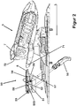
- the Figure 2 shows a rear jaw 5 of a ski binding and a ski brake 50 which is arranged in front of the rear jaw 5 in a longitudinal direction L of the ski.
- the ski brake 50 can be connected to the heel 5 so that the heel 5 and the ski brake 50 are connected to the ski as one component, or the ski brake 50 can be a separate component that can be connected to the ski independently of the heel 5 .
- the heel 4 comprises a heel holder 7 with a tread spur 71 and a sole holder 72, which is moved to a free upper side of the rear end of the ski boot sole when stepping on with the ski boot in the heel 4 in order to secure the ski boot in the ski binding.
- the ski brake 50 comprises a pedal 51 which forms a contact surface 52 for the ski boot held in the ski binding in the configuration for the descent.
- the pedal 51 is connected to brake blades 55 via a known mechanism which is not described in more detail here.
- the brake blades 55 are moved into a rest position via the mechanism, which is in the Figure 3 is shown, in which they rest on the side of the ski and can not generate a braking effect.
- the brake blades 55 can be pivoted away from the ski so that they can engage in the snow or ice in order to brake the ski.
- the ski is separated from the ski boot, for example after a fall, when the brake blades 55 can develop their braking effect.
- the ski brake 50 further comprises a brake locking element 54, with which the brake 50 in the in the Figure 3 The position shown can be locked, for example when the ski binding has the configuration for ascent, or the ski is to be transported with the binding.
- the brake locking element 54 is arranged below the contact surface 52 of the pedal 51 and can be moved linearly in the longitudinal direction L of the ski relative to the contact surface 52, as indicated by the arrows.
- the brake locking element 54 comprises a hook-shaped engaging element 56 with a nose 57 formed at the free end of the engaging element 56 which cooperates with the mechanism to secure the brake blades 55 in the configuration of the ski binding for ascent on the ski or in the configuration of the ski binding for the Release departure for braking.
- the ski brake 50 can comprise a spring element (not shown) which preloads the brake locking element 54 so that, in the configuration of the ski binding for ascent, it can automatically move into the position in which it fixes the brake blades 55 on the ski.
- the brake 50 comprises a functional element 53, the meaning of which in the description for Figure 3 is explained in more detail.
- the functional element 53 is in a pivot axis S53 with the pedal 51 and in an elongated hole 58 of the brake locking element 54 with the brake locking element 54 connected. In the position shown, the functional element 53 prevents the brake locking element 54 from being able to be displaced linearly relative to the support surface 52 of the pedal 51 in order to lock the mechanism.
- the brake 50 further comprises a climbing aid 8, which is also connected to the pedal 51 in the swivel joint formed by the swivel axis S53.
- the Figure 3 shows the heel 5 in a ski binding configuration for ascent.
- the brake pedals 55 are in the rest position and are secured in this position by the brake locking element 54, which is not visible.
- the functional element 53 was made, for example, by hand from the in FIG Figure 2 moved out position shown and is now above the contact surface 52 of the pedal 51.
- the brake locking element 54 was released now in the elongated hole 58 (see Figure 2 ) guided linearly to the contact surface 52 of the pedal 51 to intervene with the nose 57 in the movement mechanism for the brake blades 55 and thereby fix the brake blades 55 on the ski.
- the functional element 53 prevents the lower side of the ski boot sole from being lowered down to the contact surface 52 of the pedal 51 for the ascent in the configuration of the ski binding.
- the functional element 53 therefore forms a kind of first climbing aid for ascent in flat terrain.
- the functional element comprises two rollers 59 which are contacted by the underside of the ski boot sole during the ascent.
- a soft, elastic material can be used as the material of the rollers 59 in order to protect the user's joints.
- the rollers 59 can rotate on the axle that bears them, so that the functional element 53 is not loaded with unnecessary shear forces by friction, if possible.
- the heel holder 7 is shown in the open position and, when the toe piece 1 has assumed the configuration for an ascent, cannot be closed by the ski boot, since the ski boot is offset forward in the configuration for the ascent in the longitudinal direction L of the ski and therefore a rear end of the Ski boots do not contact the heel holder 7 and in particular not the tread spur 71.
- the Figure 4 shows the ski binding with the toe piece 1 with the base 2 and the heel piece 5 mounted on a ski.
- a ski boot 100 is held in the ski binding, the ski binding being in the first configuration for the descent.
- the ski brake 50 is loaded with the ski boot, so that the pedal 51 is in a lower position close to the ski surface 200 and the brake blades rest on the ski without being locked by the brake locking element 54.
- the sole underside 103 of the ski boot sole rests in the ball area on the contact plate 300 and in the heel area on the contact surface 52, the functional element 53 and the climbing aid 8 are in the respective storage positions below or level with the contact surface 52 of the pedal 51
- the contact area 52 or the sole underside 103 standing on the contact area 52 is at a height distance H1 perpendicular to the ski surface.
- the ski boot 100 assumes a first position P1 in which the heel holder 7 contacts the rear sole end 102 and the second holding device 4 contacts the front sole end.
- the ski boot 100 In the position P1, the ski boot 100 is in a rear position on the ski as seen in the longitudinal direction L of the ski, provided the heel holder 7 or the heel jaw 7 are not linearly displaceable on the ski (apart from a known length compensation in the case of a ski flex) after the ski binding was adjusted to a ski boot size, which is assumed here.
- the Figure 5 shows the ski binding of the Figure 4 with the ski boot 100 in the second configuration for the ascent.
- the functional element 53 is pivoted into its operative position, so that the ski boot 100 rests on the functional element 53 with the sole underside 103 in the heel area.
- the front sole end 101 of the ski boot is now held in the first holding device 3, the first engagement element 31 and the second engagement element 32 engage in corresponding counter-engagement elements in the front sole end 101 of the ski boot 100 and an articulation axis A1 (see FIG Figure 1 ), around which the ski boot in the ski binding is kept pivotable in the configuration for the ascent.
- the sole bottom 103 of the ski boot is in the Figure 5 , which shows the ski binding in the configuration for the ascent, does not rest on the contact plate 300 of the toe piece 1, but is held by the first holding device 3 in a position in which the sole underside 103 lies above the contact plate 300.
- the rear sole end 102 of the ski boot 100 is free to detach itself from the functional element 53 in order to be pivoted away from the ski and pivoted onto the ski or the functional element 53.
- the sole underside 103 of the ski boot 100 resting on the functional element 53 has a height distance H2 from the ski surface 200 which is greater than the height distance H1 as shown in FIG Figure 4 is shown. In the Figure 4 the height difference between the height distance H1 and the height distance H2 is shown as height compensation H21.
- the ski boot 100 takes in the Figure 5 a second position P2, in which the heel holder 7 cannot contact the rear sole end 102 and the front sole end 101 is held solely in the first holding device 3.
- the ski boot 100 was moved on the ski in the ski longitudinal direction L in the direction of the ski tip, so that it is now in position P2, a forward position on the ski.
- the positions P1 and P2 differ in that the ski boot 100 is arranged at different locations on the ski in the longitudinal direction of the ski, and at the same time a distance between the sole underside 103 and the ski surface 200 in the position P1 is different than a distance between the sole underside 103 and the ski surface 200 in the position P2.
- the different positions P1 and P2 relative to the ski are selected in such a way that they make it easier for the user to control the ski in the respective configuration and thereby increase skiing pleasure.
- the Figure 6 only differs from the Figure 5 that the climbing aid 8 now supports the rear end of the sole 102 for an ascent in steep terrain.
Landscapes
- Footwear And Its Accessory, Manufacturing Method And Apparatuses (AREA)
- Braking Elements And Transmission Devices (AREA)
- Handcart (AREA)
- Braking Arrangements (AREA)
Claims (13)
- Fixation de ski comprenant : une mâchoire avant (1) pour maintenir une extrémité de semelle avant (101) d'une chaussure de ski (100) ; et une mâchoire arrière (5) pour maintenir une extrémité de semelle arrière (102) de la chaussure de ski (100), la mâchoire arrière (5) comprenant une talonnière (7) pour maintenir l'extrémité de semelle arrière (102), la mâchoire avant (1) comprenant :• une base (2) avec laquelle la mâchoire avant (1) peut être reliée à un ski ;• un corps de mâchoire qui est relié ou peut être relié à la base (2) ou qui contribue à la formation de la base (2) ;• un premier dispositif de maintien (3), avec lequel la chaussure de ski (100) peut être reliée au ski à l'extrémité de semelle avant (101) pour une montée, comprenant un premier et un second élément d'engagement (31, 32) qui peuvent être déplacés l'un vers l'autre depuis une première position, dans laquelle ils sont à une première distance l'un de l'autre, vers une seconde position dans laquelle ils sont à une seconde distance l'un de l'autre, la seconde distance étant inférieure à la première distance, le premier élément d'engagement (31) et le second élément d'engagement (32) définissant dans la seconde position un axe d'articulation (A1) autour duquel la chaussure de ski peut pivoter avec son extrémité de semelle avant lors de la montée avec le ski ; et• un second dispositif de maintien (4) avec lequel la chaussure de ski (100) peut être reliée au ski à l'extrémité de semelle avant (101) pour une descente, le second dispositif de maintien (4) présentant une première configuration pour la descente, dans laquelle le second dispositif de maintien (4) est en contact avec l'extrémité de semelle avant (101) de la chaussure de ski (100), et une seconde configuration pour la montée dans laquelle le second dispositif de maintien (4) est hors de contact avec l'extrémité de semelle avant (101) de la chaussure de ski (100),la fixation de ski maintenant, dans la première configuration pour la descente, la chaussure de ski (100) dans une première position (P1) dans laquelle l'extrémité de semelle arrière (102) est contactée par la talonnière (7) et dans laquelle une face inférieure de semelle (103) de la chaussure de ski (100) est maintenue à un premier écartement en hauteur (H1) par rapport à une surface de ski (200),la fixation de ski maintenant, dans la seconde configuration pour la montée, la chaussure de ski (100) dans une seconde position (P2) dans laquelle l'extrémité de semelle arrière (102) n'est pas contactée par la talonnière (7) et dans laquelle la face inférieure de semelle (103) de la chaussure de ski (100) est maintenue à un second écartement en hauteur (H2) par rapport à la surface de ski (200),la chaussure de ski (100) étant disposée, vue en direction longitudinale (L) du ski, plus en arrière sur le ski dans la première position (P1) que dans la seconde position (P2), le premier écartement en hauteur (H1) par rapport à la surface de ski (200) étant inférieur au second écartement en hauteur (H2) par rapport à la surface de ski (200), la mâchoire arrière (5) comprenant un frein (50), avec une pédale (51) qui forme une surface d'appui (52) pour la chaussure de ski (100), et un élément fonctionnel (53) qui peut être déplacé par rapport à la surface d'appui (52) depuis une première situation, dans laquelle l'élément fonctionnel (53) est hors de contact avec une chaussure de ski (100) insérée dans la fixation de ski, vers une seconde situation dans laquelle l'élément fonctionnel (53) est en contact avec la chaussure de ski (100) insérée dans la fixation de ski, l'élément fonctionnel (53) équilibrant dans la seconde situation la différence en hauteur (H21) de la face inférieure de semelle (103) de l'extrémité de semelle avant (101) entre le second écartement en hauteur (H2) et le premier écartement en hauteur (H1) dans la zone de la face inférieure de semelle (103) de l'extrémité de semelle arrière (102),caractérisée en ce quele frein (50) comprend un élément de verrouillage de frein (54) qui est couplé à l'élément fonctionnel (53) de sorte que l'élément fonctionnel (53) verrouille l'élément de verrouillage de frein (54) dans la seconde situation pour la montée et libère l'élément de verrouillage de frein (54) dans la première situation pour la descente.
- Fixation de ski selon la revendication 1, dans laquelle dans la seconde situation, l'élément fonctionnel (53) se trouve au-dessus de la surface d'appui (52) et forme de préférence une première aide à la marche pour un équilibrage en hauteur égal ou inférieur à 3°, de préférence égal ou supérieur à 0°.
- Fixation de ski selon l'une quelconque des revendications précédentes, dans laquelle l'élément de verrouillage de frein (54) peut être déplacé en va-et-vient entre une première position, dans laquelle une pelle de frein (55) peut être libérée pour freiner le ski, et une seconde position dans laquelle la pelle de frein (55) peut être fixée dans une position de non-freinage, le mouvement de l'élément fonctionnel (53) libérant l'élément de verrouillage de frein (54) pour se déplacer depuis la première position vers la seconde position.
- Fixation de ski selon l'une quelconque des revendications précédentes, dans laquelle dans la première configuration pour la descente, le second dispositif de maintien (4) est couplé à la base (2) et/ou au premier dispositif de maintien (3) et peut pivoter par rapport au premier dispositif de maintien (3) autour d'un axe de pivotement (S34) entre la première configuration pour la descente et la seconde configuration pour la montée.
- Fixation de ski selon la revendication précédente, dans laquelle dans la première configuration pour la descente, l'axe de pivotement (S34) est disposé, vu en direction longitudinale (L) du ski, à un premier écartement longitudinal (L1) devant l'axe d'articulation (A1), et une surface de contact (48) pour l'extrémité de semelle avant (101) est disposée, vue en direction longitudinale (L) du ski, à un second écartement longitudinal (L2) par rapport à l'axe de pivotement (S23), le premier écartement longitudinal (L1) étant inférieur au second écartement longitudinal (L2).
- Fixation de ski selon la revendication précédente, dans laquelle une différence de longueur entre le premier écartement longitudinal (L1) et le second écartement longitudinal (L2) provoque un décalage longitudinal de la chaussure de ski (100) entre la première position (P1) et la seconde position (P2) sur le ski.
- Fixation de ski selon l'une quelconque des revendications précédentes, dans laquelle la base (2) est en outre associée à une plaque d'appui (300) qui dans la seconde configuration pour la montée n'est pas contactée par la chaussure de ski (100) grâce à une différence en hauteur (H21) entre le second écartement en hauteur (H2) et le premier écartement en hauteur (H1).
- Fixation de ski selon l'une quelconque des revendications précédentes, dans laquelle l'élément fonctionnel (53) comporte un support en forme de galet (59) monté de manière rotative sur un axe (A53) pour la face inférieure de semelle (103) de la chaussure de ski (100).
- Fixation de ski selon l'une quelconque des revendications précédentes, dans laquelle le premier dispositif de maintien (3) et le second dispositif de maintien (4) sont reliés l'un à l'autre de manière amovible.
- Fixation de ski selon l'une quelconque des revendications précédentes, dans laquelle dans la première configuration pour la descente, le premier dispositif de maintien (3) bloque le second dispositif de maintien (4) en ce que ledit au moins premier élément de blocage (31) s'engage dans un contre-élément d'engagement correspondant du second dispositif de maintien (4) ou en ce que le premier élément de blocage (31) et le second élément de blocage (32) s'engagent dans des contre-éléments d'engagement correspondants du second dispositif de maintien (4).
- Fixation de ski selon l'une quelconque des revendications précédentes, dans laquelle le frein (50) comprend une aide à la montée (8) pour la montée sur les terrains escarpés.
- Fixation de ski selon la revendication précédente, dans laquelle l'élément fonctionnel (53) et l'aide à la montée (8) sont reliés au frein (50), de préférence à la pédale (51), de manière à pouvoir pivoter dans un axe de pivotement commun (S53).
- Fixation de ski selon l'une quelconque des revendications précédentes, dans laquelle la mâchoire avant (1) et la mâchoire arrière (5) peuvent être montées fixement sur le ski et ne peuvent pas être déplacées linéairement et/ou ne peuvent pas pivoter par rapport au ski.
Applications Claiming Priority (1)
| Application Number | Priority Date | Filing Date | Title |
|---|---|---|---|
| DE102019108350.8A DE102019108350A1 (de) | 2019-03-29 | 2019-03-29 | Bremsvorrichtung |
Publications (2)
| Publication Number | Publication Date |
|---|---|
| EP3714951A1 EP3714951A1 (fr) | 2020-09-30 |
| EP3714951B1 true EP3714951B1 (fr) | 2021-12-01 |
Family
ID=68424820
Family Applications (2)
| Application Number | Title | Priority Date | Filing Date |
|---|---|---|---|
| EP19206528.2A Active EP3714951B1 (fr) | 2019-03-29 | 2019-10-31 | Fixation de ski |
| EP20164734.4A Pending EP3714952A1 (fr) | 2019-03-29 | 2020-03-20 | Dispositif de freinage |
Family Applications After (1)
| Application Number | Title | Priority Date | Filing Date |
|---|---|---|---|
| EP20164734.4A Pending EP3714952A1 (fr) | 2019-03-29 | 2020-03-20 | Dispositif de freinage |
Country Status (3)
| Country | Link |
|---|---|
| US (1) | US11154764B2 (fr) |
| EP (2) | EP3714951B1 (fr) |
| DE (1) | DE102019108350A1 (fr) |
Families Citing this family (1)
| Publication number | Priority date | Publication date | Assignee | Title |
|---|---|---|---|---|
| FR3141075B1 (fr) * | 2022-10-21 | 2025-10-17 | Rossignol Sa | Dispositif de freinage pour une planche de glisse |
Family Cites Families (59)
| Publication number | Priority date | Publication date | Assignee | Title |
|---|---|---|---|---|
| DE2906726A1 (de) * | 1979-02-21 | 1980-10-23 | Marker Hannes | Fersenstrammer fuer sicherheits-skibindungen |
| AT368018B (de) * | 1979-10-25 | 1982-08-25 | Tyrolia Freizeitgeraete | Skibremse |
| DE3048175A1 (de) * | 1980-12-19 | 1982-07-22 | Heinrich Wunder GmbH & Co KG, 8060 Dachau | Tourenbindung mit skistopper |
| DE3110743A1 (de) * | 1981-03-19 | 1982-10-07 | Hannes Marker Sicherheits-Skibindungen GmbH & Co KG, 8100 Garmisch-Partenkirchen | Skistopper |
| DE3265951D1 (en) * | 1981-03-27 | 1985-10-10 | Tmc Corp | Ski brake |
| DE3116039A1 (de) * | 1981-04-22 | 1983-10-06 | Marker Patentverwertungs Gmbh | Skistopper |
| DE3131917C2 (de) * | 1981-08-12 | 1995-07-13 | Marker Int | Fersenstrammer für eine Skibindung mit integrierter Skibremse |
| AT372007B (de) * | 1981-09-18 | 1983-08-25 | Tyrolia Freizeitgeraete | Skibremse |
| DE3140819A1 (de) * | 1981-10-13 | 1983-04-21 | ess GmbH Skibindungen, 8978 Burgberg | Skibremse |
| DE3145646A1 (de) * | 1981-11-17 | 1983-05-26 | Marker Patentverwertungsgesellschaft mbH, 6340 Baar | Skistopper |
| FR2541124A1 (fr) * | 1983-02-23 | 1984-08-24 | Salomon & Fils F | Dispositif de verrouillage pour frein de ski |
| FR2542624B1 (fr) * | 1983-03-17 | 1985-06-28 | Look Sa | Frein a ski |
| FR2596287B2 (fr) * | 1985-07-26 | 1988-11-04 | Look Sa | Frein a ski |
| AT384554B (de) * | 1986-06-03 | 1987-12-10 | Tyrolia Freizeitgeraete | Skibremse |
| FR2607712B1 (fr) * | 1986-12-04 | 1989-11-03 | Salomon Sa | Frein de ski |
| FR2610206B1 (fr) * | 1987-02-03 | 1989-02-10 | Salomon Sa | Frein de ski associe a une fixation de ski alpin, couramment appelee talonniere |
| FR2631555B1 (fr) * | 1988-05-18 | 1990-08-17 | Salomon Sa | Frein de ski |
| DE3837379C2 (de) * | 1988-11-03 | 1997-10-23 | Marker Deutschland Gmbh | Skibremse |
| US5158317A (en) * | 1988-11-03 | 1992-10-27 | Marker Deutschland Gmbh | Ski brake assembly |
| AT394495B (de) * | 1989-09-01 | 1992-04-10 | Tyrolia Freizeitgeraete | Skibremse |
| ATE123233T1 (de) * | 1989-12-15 | 1995-06-15 | Salomon Sa | Sicherheitsskibindung. |
| DE4027712A1 (de) * | 1990-08-31 | 1992-03-05 | Look Sa | Skibremse |
| IT1251777B (it) * | 1991-11-08 | 1995-05-24 | Nordica Spa | Talloniera per attacchi da sci con mezzi di riarmo automatico |
| US5642897A (en) * | 1992-02-18 | 1997-07-01 | Salomon S.A. | Ski brake and device for modifying the natural pressure distribution of a ski over its sliding surface and a ski equipped therewith |
| FR2687326B1 (fr) * | 1992-02-18 | 1995-09-29 | Salomon Sa | Dispositif visant a modifier la repartition naturelle d'un ski sur sa surface de glisse, et ski equipe d'un tel dispositif. |
| FR2687325B1 (fr) * | 1992-02-18 | 1995-10-27 | Salomon Sa | Dispositif visant a modifier la repartition naturelle d'un ski sur sa surface de glisse, et ski equipe d'un tel dispositif. |
| FR2692804B1 (fr) * | 1992-06-30 | 1994-09-16 | Salomon Sa | Fixation de ski alpin. |
| FR2707512B1 (fr) * | 1993-07-16 | 1995-09-29 | Salomon Sa | Frein de ski. |
| AT410757B (de) * | 1993-12-10 | 2003-07-25 | Tyrolia Freizeitgeraete | Skibremse |
| FR2713945B1 (fr) * | 1993-12-17 | 1996-03-29 | Salomon Sa | Dispositif interface entre un ski et des éléments de fixation. |
| AT409934B (de) * | 1994-01-28 | 2002-12-27 | Varpat Patentverwertung | Bremsvorrichtung für einen schi |
| FR2741275B1 (fr) * | 1995-11-21 | 1998-01-23 | Look Fixations Sa | Fixation de ski equipee d'un frein demontable |
| JPH10314364A (ja) * | 1997-05-16 | 1998-12-02 | Shinku:Kk | スノーボード用ストッパー |
| FR2766380B1 (fr) * | 1997-07-22 | 1999-10-08 | Look Fixations Sa | Talonniere de fixation de ski |
| US6623027B1 (en) * | 1998-06-15 | 2003-09-23 | Bryce Wheeler | Release binding and brake for telemark and cross-country skis |
| FR2779971B1 (fr) * | 1998-06-19 | 2000-08-18 | Look Fixations Sa | Element de fixation de ski alpin equipe d'un frein demontable |
| FR2788991B1 (fr) * | 1999-02-02 | 2001-04-06 | Look Fixations Sa | Frein pour ski |
| US6390491B1 (en) * | 1999-05-19 | 2002-05-21 | Lemna J. Hunter | Downhill ski with integrated binding/traction device |
| US6293576B1 (en) * | 1999-05-19 | 2001-09-25 | Mechanical Solutions, Inc. | Downhill ski with traction device |
| FR2804338B1 (fr) * | 2000-02-02 | 2002-03-08 | Look Fixations Sa | Fixation de ski a frein demontable |
| US6769711B1 (en) * | 2000-08-10 | 2004-08-03 | Ralph M. Martin | Gas powered backwards release ski binding |
| US6659494B1 (en) * | 2000-08-10 | 2003-12-09 | Ralph M. Martin | Backwards release ski binding on a pivot plate mount |
| US7207591B2 (en) * | 2001-05-08 | 2007-04-24 | Rottefella As | Ski binding |
| US6877759B2 (en) * | 2002-08-27 | 2005-04-12 | Louis Dandurand | Ski binding |
| AT500306B1 (de) * | 2003-08-06 | 2008-09-15 | Atomic Austria Gmbh | Bremsvorrichtung für einen schi |
| FR2886863B1 (fr) * | 2005-06-09 | 2008-05-23 | Look Fixations Sa Sa | Dispositif de freinage pour planche de glisse de largeur reglable |
| US7458598B2 (en) * | 2005-12-05 | 2008-12-02 | Jeffrey Giffin | Telemark binding with releasable riser plate assembly |
| WO2012024809A1 (fr) * | 2010-08-27 | 2012-03-01 | Fritschi Ag - Swiss Bindings | Fixation de ski de randonnée à talonnière comportant une zone de glissement dynamique |
| DE102012207959B4 (de) * | 2012-05-11 | 2020-11-12 | Fritz Barthel | Vordereinheit einer Gleitbrettbindung und Gleitbrettbindung |
| US8827302B2 (en) * | 2012-09-11 | 2014-09-09 | Fritschi Ag-Swiss Bindings | Automatic heel unit for a ski binding |
| DE102013201725B4 (de) * | 2013-02-01 | 2026-01-29 | Marker Deutschland Gmbh | Fersenhalter mit Verriegelungshebel |
| EP2813268A1 (fr) * | 2013-06-12 | 2014-12-17 | Fritschi AG - Swiss Bindings | Automate avant |
| EP2929919B1 (fr) * | 2014-04-09 | 2018-05-30 | Salomon S.A.S. | Fixation de ski |
| FR3040308B1 (fr) * | 2015-08-27 | 2017-08-11 | Salomon Sas | Dispositif de freinage pour fixation d'une planche de glisse |
| EP3195906B1 (fr) * | 2016-01-22 | 2018-12-26 | Fritschi AG - Swiss Bindings | Talonniere ayant une configuration de marche |
| DE102016006850A1 (de) * | 2016-02-17 | 2017-08-31 | Reinhold Zoor | Schischuhalter mit schwenkbarem Trittsporn |
| US10463946B2 (en) * | 2017-06-07 | 2019-11-05 | G3 Genuine Guide Gear Inc. | Touring binding heel unit |
| FR3069445B1 (fr) * | 2017-07-31 | 2021-02-19 | Rossignol Sa | Dispositif de freinage pour ski de randonnee |
| US10315099B2 (en) * | 2017-10-31 | 2019-06-11 | G3 Genuine Guide Gear Inc. | Lightweight touring binding heel unit |
-
2019
- 2019-03-29 DE DE102019108350.8A patent/DE102019108350A1/de active Pending
- 2019-10-31 EP EP19206528.2A patent/EP3714951B1/fr active Active
-
2020
- 2020-03-20 EP EP20164734.4A patent/EP3714952A1/fr active Pending
- 2020-03-26 US US16/830,712 patent/US11154764B2/en active Active
Also Published As
| Publication number | Publication date |
|---|---|
| US20200306615A1 (en) | 2020-10-01 |
| EP3714952A1 (fr) | 2020-09-30 |
| DE102019108350A1 (de) | 2020-10-01 |
| US11154764B2 (en) | 2021-10-26 |
| EP3714951A1 (fr) | 2020-09-30 |
Similar Documents
| Publication | Publication Date | Title |
|---|---|---|
| DE202009019128U1 (de) | Zeheneinheit für Tourenskibindung | |
| DE19635250A1 (de) | Automatische Befestigungsvorrichtung | |
| EP2666525B1 (fr) | Talonnière avec cale de montée et ensemble stop-ski | |
| EP0890379B2 (fr) | Fixation de ski | |
| DE3437725C2 (de) | Vordere Sohlenhaltevorrichtung | |
| DE2521726A1 (de) | Fersenbindung fuer langlauf-schistiefel | |
| EP3714951B1 (fr) | Fixation de ski | |
| EP1181961B1 (fr) | Fixation de ski | |
| EP3332843B1 (fr) | Unité de talon pour une fixation de planche de glisse dotée d'un systeme de frein | |
| CH706664B1 (de) | Skibindung. | |
| EP3195907B1 (fr) | Talonnière pour une fixation de ski de randonnée | |
| DE3227237C1 (de) | Sicherheitsbindung für Ski | |
| EP0877642B1 (fr) | Fixation de snowboard | |
| EP2754469B1 (fr) | Couteau a neige | |
| DE1988139U (de) | Fersenteil fuer eine ski-sicherheitsbindung. | |
| EP0031570A1 (fr) | Fixation de sécurité pour ski avec chaussure de ski intégrante | |
| EP2821114B1 (fr) | Système de fixation de sécurité | |
| EP0665035B1 (fr) | Dispositif de fixation sur un ski | |
| EP4173682B1 (fr) | Fixation de ski, en particulier fixation de ski de randonnée | |
| EP3453431B1 (fr) | Talonniere | |
| AT378126B (de) | Rueckgleitsperre fuer langlaufschi | |
| CH618885A5 (fr) | ||
| DE599013C (de) | Abnehmbare Skibindung mit zweiteiliger drehbarer Metallsohle | |
| AT360398B (de) | Skibindung | |
| EP3115089B1 (fr) | Talonnière |
Legal Events
| Date | Code | Title | Description |
|---|---|---|---|
| PUAI | Public reference made under article 153(3) epc to a published international application that has entered the european phase |
Free format text: ORIGINAL CODE: 0009012 |
|
| STAA | Information on the status of an ep patent application or granted ep patent |
Free format text: STATUS: THE APPLICATION HAS BEEN PUBLISHED |
|
| AK | Designated contracting states |
Kind code of ref document: A1 Designated state(s): AL AT BE BG CH CY CZ DE DK EE ES FI FR GB GR HR HU IE IS IT LI LT LU LV MC MK MT NL NO PL PT RO RS SE SI SK SM TR |
|
| AX | Request for extension of the european patent |
Extension state: BA ME |
|
| STAA | Information on the status of an ep patent application or granted ep patent |
Free format text: STATUS: REQUEST FOR EXAMINATION WAS MADE |
|
| 17P | Request for examination filed |
Effective date: 20201118 |
|
| RBV | Designated contracting states (corrected) |
Designated state(s): AL AT BE BG CH CY CZ DE DK EE ES FI FR GB GR HR HU IE IS IT LI LT LU LV MC MK MT NL NO PL PT RO RS SE SI SK SM TR |
|
| GRAP | Despatch of communication of intention to grant a patent |
Free format text: ORIGINAL CODE: EPIDOSNIGR1 |
|
| STAA | Information on the status of an ep patent application or granted ep patent |
Free format text: STATUS: GRANT OF PATENT IS INTENDED |
|
| INTG | Intention to grant announced |
Effective date: 20210713 |
|
| GRAS | Grant fee paid |
Free format text: ORIGINAL CODE: EPIDOSNIGR3 |
|
| GRAA | (expected) grant |
Free format text: ORIGINAL CODE: 0009210 |
|
| STAA | Information on the status of an ep patent application or granted ep patent |
Free format text: STATUS: THE PATENT HAS BEEN GRANTED |
|
| AK | Designated contracting states |
Kind code of ref document: B1 Designated state(s): AL AT BE BG CH CY CZ DE DK EE ES FI FR GB GR HR HU IE IS IT LI LT LU LV MC MK MT NL NO PL PT RO RS SE SI SK SM TR |
|
| REG | Reference to a national code |
Ref country code: GB Ref legal event code: FG4D Free format text: NOT ENGLISH |
|
| REG | Reference to a national code |
Ref country code: AT Ref legal event code: REF Ref document number: 1451216 Country of ref document: AT Kind code of ref document: T Effective date: 20211215 Ref country code: CH Ref legal event code: EP |
|
| REG | Reference to a national code |
Ref country code: IE Ref legal event code: FG4D Free format text: LANGUAGE OF EP DOCUMENT: GERMAN |
|
| REG | Reference to a national code |
Ref country code: DE Ref legal event code: R096 Ref document number: 502019002910 Country of ref document: DE |
|
| REG | Reference to a national code |
Ref country code: LT Ref legal event code: MG9D |
|
| REG | Reference to a national code |
Ref country code: NL Ref legal event code: MP Effective date: 20211201 |
|
| PG25 | Lapsed in a contracting state [announced via postgrant information from national office to epo] |
Ref country code: RS Free format text: LAPSE BECAUSE OF FAILURE TO SUBMIT A TRANSLATION OF THE DESCRIPTION OR TO PAY THE FEE WITHIN THE PRESCRIBED TIME-LIMIT Effective date: 20211201 Ref country code: LT Free format text: LAPSE BECAUSE OF FAILURE TO SUBMIT A TRANSLATION OF THE DESCRIPTION OR TO PAY THE FEE WITHIN THE PRESCRIBED TIME-LIMIT Effective date: 20211201 Ref country code: FI Free format text: LAPSE BECAUSE OF FAILURE TO SUBMIT A TRANSLATION OF THE DESCRIPTION OR TO PAY THE FEE WITHIN THE PRESCRIBED TIME-LIMIT Effective date: 20211201 Ref country code: BG Free format text: LAPSE BECAUSE OF FAILURE TO SUBMIT A TRANSLATION OF THE DESCRIPTION OR TO PAY THE FEE WITHIN THE PRESCRIBED TIME-LIMIT Effective date: 20220301 |
|
| PG25 | Lapsed in a contracting state [announced via postgrant information from national office to epo] |
Ref country code: SE Free format text: LAPSE BECAUSE OF FAILURE TO SUBMIT A TRANSLATION OF THE DESCRIPTION OR TO PAY THE FEE WITHIN THE PRESCRIBED TIME-LIMIT Effective date: 20211201 Ref country code: PL Free format text: LAPSE BECAUSE OF FAILURE TO SUBMIT A TRANSLATION OF THE DESCRIPTION OR TO PAY THE FEE WITHIN THE PRESCRIBED TIME-LIMIT Effective date: 20211201 Ref country code: NO Free format text: LAPSE BECAUSE OF FAILURE TO SUBMIT A TRANSLATION OF THE DESCRIPTION OR TO PAY THE FEE WITHIN THE PRESCRIBED TIME-LIMIT Effective date: 20220301 Ref country code: LV Free format text: LAPSE BECAUSE OF FAILURE TO SUBMIT A TRANSLATION OF THE DESCRIPTION OR TO PAY THE FEE WITHIN THE PRESCRIBED TIME-LIMIT Effective date: 20211201 Ref country code: HR Free format text: LAPSE BECAUSE OF FAILURE TO SUBMIT A TRANSLATION OF THE DESCRIPTION OR TO PAY THE FEE WITHIN THE PRESCRIBED TIME-LIMIT Effective date: 20211201 Ref country code: GR Free format text: LAPSE BECAUSE OF FAILURE TO SUBMIT A TRANSLATION OF THE DESCRIPTION OR TO PAY THE FEE WITHIN THE PRESCRIBED TIME-LIMIT Effective date: 20220302 |
|
| PG25 | Lapsed in a contracting state [announced via postgrant information from national office to epo] |
Ref country code: NL Free format text: LAPSE BECAUSE OF FAILURE TO SUBMIT A TRANSLATION OF THE DESCRIPTION OR TO PAY THE FEE WITHIN THE PRESCRIBED TIME-LIMIT Effective date: 20211201 |
|
| PG25 | Lapsed in a contracting state [announced via postgrant information from national office to epo] |
Ref country code: SM Free format text: LAPSE BECAUSE OF FAILURE TO SUBMIT A TRANSLATION OF THE DESCRIPTION OR TO PAY THE FEE WITHIN THE PRESCRIBED TIME-LIMIT Effective date: 20211201 Ref country code: SK Free format text: LAPSE BECAUSE OF FAILURE TO SUBMIT A TRANSLATION OF THE DESCRIPTION OR TO PAY THE FEE WITHIN THE PRESCRIBED TIME-LIMIT Effective date: 20211201 Ref country code: RO Free format text: LAPSE BECAUSE OF FAILURE TO SUBMIT A TRANSLATION OF THE DESCRIPTION OR TO PAY THE FEE WITHIN THE PRESCRIBED TIME-LIMIT Effective date: 20211201 Ref country code: PT Free format text: LAPSE BECAUSE OF FAILURE TO SUBMIT A TRANSLATION OF THE DESCRIPTION OR TO PAY THE FEE WITHIN THE PRESCRIBED TIME-LIMIT Effective date: 20220401 Ref country code: ES Free format text: LAPSE BECAUSE OF FAILURE TO SUBMIT A TRANSLATION OF THE DESCRIPTION OR TO PAY THE FEE WITHIN THE PRESCRIBED TIME-LIMIT Effective date: 20211201 Ref country code: EE Free format text: LAPSE BECAUSE OF FAILURE TO SUBMIT A TRANSLATION OF THE DESCRIPTION OR TO PAY THE FEE WITHIN THE PRESCRIBED TIME-LIMIT Effective date: 20211201 Ref country code: CZ Free format text: LAPSE BECAUSE OF FAILURE TO SUBMIT A TRANSLATION OF THE DESCRIPTION OR TO PAY THE FEE WITHIN THE PRESCRIBED TIME-LIMIT Effective date: 20211201 |
|
| REG | Reference to a national code |
Ref country code: DE Ref legal event code: R097 Ref document number: 502019002910 Country of ref document: DE |
|
| PG25 | Lapsed in a contracting state [announced via postgrant information from national office to epo] |
Ref country code: IS Free format text: LAPSE BECAUSE OF FAILURE TO SUBMIT A TRANSLATION OF THE DESCRIPTION OR TO PAY THE FEE WITHIN THE PRESCRIBED TIME-LIMIT Effective date: 20220401 |
|
| PLBE | No opposition filed within time limit |
Free format text: ORIGINAL CODE: 0009261 |
|
| STAA | Information on the status of an ep patent application or granted ep patent |
Free format text: STATUS: NO OPPOSITION FILED WITHIN TIME LIMIT |
|
| PG25 | Lapsed in a contracting state [announced via postgrant information from national office to epo] |
Ref country code: DK Free format text: LAPSE BECAUSE OF FAILURE TO SUBMIT A TRANSLATION OF THE DESCRIPTION OR TO PAY THE FEE WITHIN THE PRESCRIBED TIME-LIMIT Effective date: 20211201 Ref country code: AL Free format text: LAPSE BECAUSE OF FAILURE TO SUBMIT A TRANSLATION OF THE DESCRIPTION OR TO PAY THE FEE WITHIN THE PRESCRIBED TIME-LIMIT Effective date: 20211201 |
|
| 26N | No opposition filed |
Effective date: 20220902 |
|
| PG25 | Lapsed in a contracting state [announced via postgrant information from national office to epo] |
Ref country code: SI Free format text: LAPSE BECAUSE OF FAILURE TO SUBMIT A TRANSLATION OF THE DESCRIPTION OR TO PAY THE FEE WITHIN THE PRESCRIBED TIME-LIMIT Effective date: 20211201 |
|
| PG25 | Lapsed in a contracting state [announced via postgrant information from national office to epo] |
Ref country code: MC Free format text: LAPSE BECAUSE OF FAILURE TO SUBMIT A TRANSLATION OF THE DESCRIPTION OR TO PAY THE FEE WITHIN THE PRESCRIBED TIME-LIMIT Effective date: 20211201 Ref country code: IT Free format text: LAPSE BECAUSE OF FAILURE TO SUBMIT A TRANSLATION OF THE DESCRIPTION OR TO PAY THE FEE WITHIN THE PRESCRIBED TIME-LIMIT Effective date: 20211201 |
|
| P01 | Opt-out of the competence of the unified patent court (upc) registered |
Effective date: 20230515 |
|
| REG | Reference to a national code |
Ref country code: BE Ref legal event code: MM Effective date: 20221031 |
|
| PG25 | Lapsed in a contracting state [announced via postgrant information from national office to epo] |
Ref country code: LU Free format text: LAPSE BECAUSE OF NON-PAYMENT OF DUE FEES Effective date: 20221031 |
|
| PG25 | Lapsed in a contracting state [announced via postgrant information from national office to epo] |
Ref country code: BE Free format text: LAPSE BECAUSE OF NON-PAYMENT OF DUE FEES Effective date: 20221031 |
|
| PG25 | Lapsed in a contracting state [announced via postgrant information from national office to epo] |
Ref country code: IE Free format text: LAPSE BECAUSE OF NON-PAYMENT OF DUE FEES Effective date: 20221031 |
|
| PG25 | Lapsed in a contracting state [announced via postgrant information from national office to epo] |
Ref country code: CY Free format text: LAPSE BECAUSE OF FAILURE TO SUBMIT A TRANSLATION OF THE DESCRIPTION OR TO PAY THE FEE WITHIN THE PRESCRIBED TIME-LIMIT Effective date: 20211201 |
|
| PG25 | Lapsed in a contracting state [announced via postgrant information from national office to epo] |
Ref country code: MK Free format text: LAPSE BECAUSE OF FAILURE TO SUBMIT A TRANSLATION OF THE DESCRIPTION OR TO PAY THE FEE WITHIN THE PRESCRIBED TIME-LIMIT Effective date: 20211201 Ref country code: HU Free format text: LAPSE BECAUSE OF FAILURE TO SUBMIT A TRANSLATION OF THE DESCRIPTION OR TO PAY THE FEE WITHIN THE PRESCRIBED TIME-LIMIT; INVALID AB INITIO Effective date: 20191031 |
|
| GBPC | Gb: european patent ceased through non-payment of renewal fee |
Effective date: 20231031 |
|
| PG25 | Lapsed in a contracting state [announced via postgrant information from national office to epo] |
Ref country code: GB Free format text: LAPSE BECAUSE OF NON-PAYMENT OF DUE FEES Effective date: 20231031 |
|
| PG25 | Lapsed in a contracting state [announced via postgrant information from national office to epo] |
Ref country code: GB Free format text: LAPSE BECAUSE OF NON-PAYMENT OF DUE FEES Effective date: 20231031 |
|
| PG25 | Lapsed in a contracting state [announced via postgrant information from national office to epo] |
Ref country code: MT Free format text: LAPSE BECAUSE OF FAILURE TO SUBMIT A TRANSLATION OF THE DESCRIPTION OR TO PAY THE FEE WITHIN THE PRESCRIBED TIME-LIMIT Effective date: 20211201 |
|
| REG | Reference to a national code |
Ref country code: CH Ref legal event code: U11 Free format text: ST27 STATUS EVENT CODE: U-0-0-U10-U11 (AS PROVIDED BY THE NATIONAL OFFICE) Effective date: 20251101 |
|
| PG25 | Lapsed in a contracting state [announced via postgrant information from national office to epo] |
Ref country code: TR Free format text: LAPSE BECAUSE OF FAILURE TO SUBMIT A TRANSLATION OF THE DESCRIPTION OR TO PAY THE FEE WITHIN THE PRESCRIBED TIME-LIMIT Effective date: 20211201 |
|
| PGFP | Annual fee paid to national office [announced via postgrant information from national office to epo] |
Ref country code: DE Payment date: 20251030 Year of fee payment: 7 |
|
| PGFP | Annual fee paid to national office [announced via postgrant information from national office to epo] |
Ref country code: AT Payment date: 20251023 Year of fee payment: 7 |
|
| PGFP | Annual fee paid to national office [announced via postgrant information from national office to epo] |
Ref country code: FR Payment date: 20251024 Year of fee payment: 7 |
|
| PGFP | Annual fee paid to national office [announced via postgrant information from national office to epo] |
Ref country code: CH Payment date: 20251101 Year of fee payment: 7 |