EP3714952A1 - Dispositif de freinage - Google Patents
Dispositif de freinage Download PDFInfo
- Publication number
- EP3714952A1 EP3714952A1 EP20164734.4A EP20164734A EP3714952A1 EP 3714952 A1 EP3714952 A1 EP 3714952A1 EP 20164734 A EP20164734 A EP 20164734A EP 3714952 A1 EP3714952 A1 EP 3714952A1
- Authority
- EP
- European Patent Office
- Prior art keywords
- braking device
- functional element
- arm
- gliding board
- pedal
- Prior art date
- Legal status (The legal status is an assumption and is not a legal conclusion. Google has not performed a legal analysis and makes no representation as to the accuracy of the status listed.)
- Pending
Links
Images




Classifications
-
- A—HUMAN NECESSITIES
- A63—SPORTS; GAMES; AMUSEMENTS
- A63C—SKATES; SKIS; ROLLER SKATES; DESIGN OR LAYOUT OF COURTS, RINKS OR THE LIKE
- A63C9/00—Ski bindings
- A63C9/08—Ski bindings yieldable or self-releasing in the event of an accident, i.e. safety bindings
- A63C9/0807—Ski bindings yieldable or self-releasing in the event of an accident, i.e. safety bindings for both towing and downhill skiing
-
- A—HUMAN NECESSITIES
- A63—SPORTS; GAMES; AMUSEMENTS
- A63C—SKATES; SKIS; ROLLER SKATES; DESIGN OR LAYOUT OF COURTS, RINKS OR THE LIKE
- A63C7/00—Devices preventing skis from slipping back; Ski-stoppers or ski-brakes
- A63C7/10—Hinged stoppage blades attachable to the skis in such manner that these blades can be moved out of the operative position
- A63C7/1006—Ski-stoppers
- A63C7/1013—Ski-stoppers actuated by the boot
-
- A—HUMAN NECESSITIES
- A63—SPORTS; GAMES; AMUSEMENTS
- A63C—SKATES; SKIS; ROLLER SKATES; DESIGN OR LAYOUT OF COURTS, RINKS OR THE LIKE
- A63C7/00—Devices preventing skis from slipping back; Ski-stoppers or ski-brakes
- A63C7/10—Hinged stoppage blades attachable to the skis in such manner that these blades can be moved out of the operative position
- A63C7/1006—Ski-stoppers
-
- A—HUMAN NECESSITIES
- A63—SPORTS; GAMES; AMUSEMENTS
- A63C—SKATES; SKIS; ROLLER SKATES; DESIGN OR LAYOUT OF COURTS, RINKS OR THE LIKE
- A63C7/00—Devices preventing skis from slipping back; Ski-stoppers or ski-brakes
- A63C7/10—Hinged stoppage blades attachable to the skis in such manner that these blades can be moved out of the operative position
- A63C7/1093—Details
-
- A—HUMAN NECESSITIES
- A63—SPORTS; GAMES; AMUSEMENTS
- A63C—SKATES; SKIS; ROLLER SKATES; DESIGN OR LAYOUT OF COURTS, RINKS OR THE LIKE
- A63C9/00—Ski bindings
- A63C9/006—Ski bindings with a climbing wedge
-
- A—HUMAN NECESSITIES
- A63—SPORTS; GAMES; AMUSEMENTS
- A63C—SKATES; SKIS; ROLLER SKATES; DESIGN OR LAYOUT OF COURTS, RINKS OR THE LIKE
- A63C9/00—Ski bindings
- A63C9/08—Ski bindings yieldable or self-releasing in the event of an accident, i.e. safety bindings
- A63C9/085—Ski bindings yieldable or self-releasing in the event of an accident, i.e. safety bindings with sole hold-downs, e.g. swingable
- A63C9/08507—Ski bindings yieldable or self-releasing in the event of an accident, i.e. safety bindings with sole hold-downs, e.g. swingable with a plurality of mobile jaws
- A63C9/08528—Ski bindings yieldable or self-releasing in the event of an accident, i.e. safety bindings with sole hold-downs, e.g. swingable with a plurality of mobile jaws pivoting about a longitudinal axis
Definitions
- the invention relates to a braking device for a gliding board with a base for connecting the braking device to the gliding board, a brake with at least one braking element, a locking element which is between a first position in which the braking element is exposed for braking the gliding board and a second position , in which the braking element is fixed in a non-braking position, can be moved back and forth, and a pedal which comprises a contact surface for a shoe and a functional element, wherein the functional element can be moved relative to the contact surface.
- Gliding board bindings which are also suitable for an ascent with the gliding board, are becoming increasingly popular.
- these bindings In addition to a downhill mode (as with normal alpine bindings), these bindings also enable a touring mode.
- touring mode the shoe is held pivotably on the toe piece while the shoe heel can lift off the gliding board.
- An important safety aspect of these bindings is that a braking device of the gliding board binding reliably brakes the gliding board in the descent mode if it comes off the shoe, for example due to a fall. In the touring mode, however, the braking device should be reliably prevented from being triggered. There is therefore a need for braking devices that can be reliably triggered in downhill mode and safely held in a non-braking position in touring mode.
- One aspect of the invention relates to a braking device for a gliding board with a base for connecting the braking device to the gliding board, a brake with at least one braking element, a locking element which is between a first position in which the braking element is exposed for braking the gliding board, and a second position, in which the braking element is fixed in a non-braking position, can be moved back and forth, and a pedal comprising a contact surface for a shoe and a functional element, wherein the functional element can be moved relative to the contact surface, whereby by the movement of the functional element, the locking element is released to move from the first position to the second position, and vice versa.
- the gliding board binding can be a combined touring and downhill binding, with a toe piece that connects a front end of the shoe to the gliding board in touring mode and in downhill mode, and a heel that connects the rear end to the gliding board in downhill mode.
- the base can be connected directly to the gliding board, for example via screws or locking elements comprised by the base, which engage in counter-locking elements on the gliding board in order to connect the base and the gliding board with one another in a form-fitting and / or force-locking manner.
- the base can be pushed onto a rail that is enclosed by the gliding board or can be connected to the gliding board, moved on the rail into a functional position and there connected to the gliding board or fixed relative to the gliding board.
- Other types of connection known in the field of gliding boards between gliding board binding elements such as toe cheeks, heel cheeks or brakes, are also encompassed by the invention.
- the braking element can be a known brake blade, which is pressed into or against the driving surface, for example by spring force, in order to brake the gliding board if, for example, it has become detached from the shoe in the event of a fall.
- the brake comprises two brake elements which are coupled to one another in terms of movement and can be moved into the braking position essentially simultaneously on both sides of the sliding board.
- the locking element can comprise an engagement element that, for locking the brake in the non-braking position, interacts with a counter-locking element on the base or the brake or another part that is immovable relative to the gliding board. During the movement from the first position into the second position or vice versa, the locking element can be moved linearly, rotated, pivoted or moved in some other way.
- the movement of the functional element relative to the contact surface can be a linear movement, preferably along or transversely to a longitudinal axis of the sliding board, a pivoting movement about a pivoting axis that preferably runs transversely or parallel to the longitudinal axis of the sliding board, or a rotational movement that is about an axis of rotation that Act at an angle upwards from the gliding board surface towards the shoe.
- the movement of the functional element can release the movement of the brake, that is, it can only make the movement of the brake from the non-braking position into a position in which the brake can act possible.
- the functional element can be moved from a first position, in which the functional element is out of contact with a shoe inserted in the binding, into a second position, in which the functional element is in contact with the inserted shoe.
- An inserted shoe can mean that the binding is in downhill mode, i.e. the shoe is held firmly in the toe piece and in the heel holder.
- a shoe that is used in touring mode means that the shoe is held by the toe piece.
- one Form the pivot axis for the shoe so that the shoe can lift freely from the gliding board but can also be lowered in the direction of the brake pedal.
- the first position of the functional element represents a downhill mode of the brake
- the second position of the functional element represents a touring mode of the brake.
- Being in contact can mean that the functional element rests against the shoe and the shoe prevents the functional element from moving unintentionally from the second position to the first position.
- To move the functional element from the first position into the second position it may be necessary for the shoe, or an underside of the sole of the shoe, to be arranged at a distance from the contact area, that is, above or next to the contact area.
- the functional element remains in the second position even when it is not in contact with the shoe.
- the functional element In the second position, the functional element can for example lie above or on the surface of the contact area.
- the shoe used can then be lowered down to the functional element, so that the functional element in the second position in touring mode in particular forms a first climbing aid for height compensation of ⁇ 3 °, preferably 0 °.
- the functional element can be designed as a lever.
- the lever can have a first connecting arm with a first end and a second end and preferably additionally a second connecting arm with a first end and a second end.
- the connecting arm (s) can be supported and / or guided with the second end in the pedal, while the first end (s) can be gripped with a tool or preferably by hand to move the lever from the first position to the second Able to move back and forth.
- the lever with a first connecting arm and a second connecting arm can additionally comprise a cross strut which connects the first end of the first connecting arm to the first end of the second connecting arm.
- the cross strut can be designed so that it can be gripped with a tool or by hand in order to move the lever from the first position to the second position and back.
- the first connecting arm can be connected with its second end and the second connecting arm with its second end in a linear guide or a swivel or swivel joint with the pedal.
- the cross strut can be rotatably mounted in the first end of the first connecting arm and in the first end of the second connecting arm.
- the two connecting arms can have a bore at the respective end into which the axis-like ends of the cross brace engage.
- the cross strut can be made of the same material or a different material than the two connecting arms.
- the surface of the cross strut can have a structure, for example grooves in the circumferential direction or in the longitudinal direction of the cross strut or other structure-forming elements.
- the cross strut can have a coating which consists for example of an elastic material such as a plastic.
- the cross strut can be secured against sideways stepping out of the first connecting arm and the second connecting arm.
- the cross strut can comprise at least one sleeve which surrounds it at least partially in the longitudinal direction of the cross strut and is rotatably mounted on the cross strut.
- the sleeve is preferably closed in the circumferential direction, so that it can only be pushed onto the cross strut from the side or removed from the cross strut.
- the sleeve can be formed from a plastic or comprise a plastic coating, wherein the plastic can be an elastic plastic.
- the outer surface of the sleeve can have a structure.
- the rotatable cross strut or cross strut with the rotatable sleeve can be advantageous if the shoe, or the sole underside of the shoe, has a pronounced profile, in which the cross strut can engage when the functional element is in the second position. This prevents the lever from jamming in the profile, which would make walking in touring mode more difficult.
- Another advantage can be that the shoe, which is linear relative to the sliding board due to bending of the sliding board Gliding board is moved in or against the longitudinal direction of the gliding board, no frictional forces of the cross strut or the sleeve have to be overcome.
- the functional element can be connected to the pedal so as to be pivotable about an axis transverse to the longitudinal direction of the gliding board. It can have a U-shape, with internal dimensions that essentially correspond to the external dimensions of the pedal. In the first position, the functional element can lie below a plane that spans the contact surface or the pedal; in the second position, the functional element can rest on the pedal at least at one point, in a line or flat.
- the locking element can be preloaded in the direction of the first or the second position so that the locking element moves automatically or at least supported by the preloading force into the first or second position when the functional element is moved from the first or second position to the second or first position.
- the locking element is preferably pretensioned in the direction of the second position.
- the functional element can form a stop for the locking element in the first position and thereby hold the locking element in the first position.
- the braking device can comprise at least one second climbing aid which can be moved from a rest position into an active position, for example pivoted or linearly displaced.
- This second climbing aid can be secured to the pedal in a form-fitting and / or force-locking manner in a rest position, so that the second climbing aid cannot unintentionally move from the rest position into the active position.
- the second climbing aid can increase the area of the pedal or the contact area for the shoe in the rest position.
- the second climbing aid can lengthen the surface in the direction of the longitudinal axis of the gliding board and / or widen it in the transverse direction.
- the second climbing aid can also be arranged in the rest position relative to the pedal in such a way that it does not contribute to the enlargement of the pedal or the contact area.
- the second climbing aid in the rest position, can also partially lie within the contact area and preferably also form a surface of the pedal.
- the second climbing aid can be U-shaped like the functional element.
- the cross strut of the second climbing aid can be arranged in the rest position on a side of the pedal which is opposite the side on which the functional element is arranged in the first position.
- the second climbing aid can be arranged in the rest position with respect to the longitudinal axis of the gliding board behind the functional element in the direction of gliding board travel.
- the U-shaped second climbing aid can, like the functional element, comprise two connecting arms each with a free end and a cross strut which connects the two connecting arms to one another at an end region of the connecting arms opposite the free ends.
- the second climbing aid can be originally formed in one piece, for example cast in a die-casting process or assembled from several parts. With the first free ends, the second climbing aid can be movably connected to the pedal or the base, for example movably linearly, pivotably or rotatably.
- Both the functional element and the second climbing aid can each be connected to the base or the pedal in a joint, such as a swivel or swivel joint.
- the functional element can be connected in a first joint and the climbing aid in a second joint.
- the first joint is preferably identical to the second joint, so that the functional element and the second climbing aid form the same joint with the base or the pedal and can be moved in the same joint relative to the base and relative to the pedal and relative to one another.
- the common joint can be formed near a front end in the sliding board running direction of the braking device connected to the sliding board
- the second climbing aid can provide a height compensation that is greater than the height compensation of the functional element in the second position.
- the second climbing aid preferably offers a height compensation of approx. 10 °.
- the connecting arms of the second climbing aid have a greater length than the connecting arms of the functional element.
- the second climbing aid can preferably only be moved out of the rest position when the functional element is in the second position.
- the second climbing aid can be locked in at least one angular position or in two, three or more angular positions that effect different height compensations.
- at least one of the connecting arms or both connecting arms of the second climbing aid can have an extension at their free ends, for example, which are designed as latching fingers or stop elements.
- the locking element or the locking elements for the locking fingers or a stop for the stop element (s) of the second climbing aid can be formed on an outside of the base or of the pedal.
- the base of the braking device can have a drilling pattern which is identical to a drilling pattern of a known heel holder, so that the braking device together with the heel holder with the same, for example, screw in the same hole can be connected to the gliding board.
- the base can have a section into which any drilling pattern can be introduced subsequently in order to be able to combine the braking device with a large number of different heel holders.
- a rail that can be connected to the gliding board by suitable means and onto which a buttock can be pushed can also be regarded as belonging to the heel holder.
- the locking element can have a first arm that runs essentially parallel to an upper side of the pedal, with a free end that rests on the functional element directly or via one or more movement and / or force transmission elements when the functional element is in the first position .
- the free end of the first arm of the locking element can be shaped such that the locking element can be moved from the second position to the first position when the functional element is moved from the second position to the first position, and vice versa.
- the first arm can have a longitudinal extension Have braking device longitudinal direction, which corresponds substantially to the longitudinal extent in the braking device longitudinal direction of the contact surface or the pedal, or is shorter.
- the locking element can comprise at least one second arm which protrudes at an angle from the first arm.
- the angle can be selected as desired by the person skilled in the art, it can for example be between 70 ° and 110 °, or essentially 90 °.
- the second arm, which protrudes from the first arm can comprise a free end which forms an engagement element of the locking element which cooperates with a counter-locking element of the braking device to the brake in the second position, for example in touring mode or for transport Set sliding board.
- the locking element can furthermore comprise at least one third arm which protrudes from the first arm, for example between the free end of the first arm and the at least one second arm.
- the at least one third arm can protrude in any direction at any angle from the first arm, for example it can protrude in the same direction as the at least one second arm and run parallel to it.
- the at least one third arm can, for example, form a counter-bearing for a tensioning element which biases the locking element into the second position.
- the tensioning element can be a spring, for example a spiral spring, a leaf spring or a solid body made of an elastic material.
- a second aspect of the invention relates to a ski binding for a gliding board with a toe piece or toe holder, a heel piece or heel holder and a braking device as described in relation to the first aspect.
- the toe piece of the ski binding can comprise a first holding device for a front end of a boot and a second holding device for the front end of the boot.
- the first holding device can connect the front end of the shoe to the gliding board when walking and the second holding device can connect the front end of the shoe to the gliding board when descending.
- the second holding device can be detachably connected to the first holding device, so that the second holding device can be removed and carried separately from the first holding device for walking or in the touring mode of the gliding board binding.
- the second holding device In downhill mode, the second holding device preferably enables the shoe to be released from the side in the event of a fall.
- the heel holder can be any heel piece that securely connects the shoe to the gliding board for the descent.
- the buttock can be rotatable about an axis which runs essentially parallel to the upper side of the gliding board in order to allow the gliding board binding to be released vertically on descent.
- the heel holder can preferably not be closed as long as the functional element is in the second position in which it fixes the brake in the non-braking position. This prevents the gliding board from being able to be used for descent despite the missing braking function of the braking device.
- the braking device can partially overlap the heel holder.
- the hole pattern of the braking device can be aligned with a hole pattern of the heel holder.
- the braking device engages over or under the heel holder in the area of the aligned drilling patterns.
- a connecting element can extend through aligned bores of the braking device and the heel holder, and connect the braking device and heel holder together with the gliding board.
- a third aspect of the invention relates to a gliding board with a ski binding according to the second aspect.
- a fourth aspect relates to the braking device according to the first aspect, the braking device with all parts serving as a retrofit kit for a known gliding board binding.
- the retrofit kit with all parts of the braking device is enclosed in an outer packaging and can be offered as a separate set in a sales room for sale to end customers, independently of a gliding board binding.
- the user in order to switch from downhill mode to touring mode, the user has to get out of the binding, which triggers the braking device, i.e. the pedal can move upwards relative to the gliding board and at the same time the braking elements of the brake can move in the opposite direction.
- the user can move the functional element from the first position to the second position, whereby the locking element moves from the first position to the second position and the gliding board can be used for the touring mode.
- the user presses the pedal down in the direction of the gliding board and thereby presses the locking element, which is now in the second position, into the locking with the brake, which means that the braking elements can no longer be released.
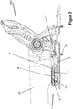
- the Figure 1 shows an embodiment of a heel holder 100 with a braking device 1 for a gliding board or ski binding, in particular a binding with which the gliding board can be used in a touring mode and in a downhill mode.
- the braking device 1 comprises a base 2, a pedal 4 and at least one braking element 3, which is pressed against the ground, such as ice or snow, to brake the sliding board released from the shoe.
- the base 2 comprises a connection area 22 with a drilling pattern 8, which is arranged next to the pedal 4 in the braking device longitudinal direction L.
- the drilling pattern 8 is designed so that it is with one in the Figure 1
- the not visible drilling pattern of the heel holder 100 is aligned so that the braking device 1 and the heel holder 100 can be connected to the gliding board together with the same fastening element 81.
- the base 2 is pushed onto a rail which can be connected to the sliding board 1 or which is also formed by the sliding board 1.
- the pedal 4 is located in the braking device longitudinal direction L in front of or next to a heel shoe of the heel holder (100).
- the pedal 4 comprises a contact surface 41 with a surface 411.
- a functional element 5, a second climbing aid 7 and a locking element 6 are connected to the pedal (see FIG Figure 3 ), of which in the Figure 1 only the free end 611 is visible.
- the functional element 5 and the second climbing aid 7 are movably supported in a common swivel joint D1 in the pedal 4 and can be pivoted relative to the pedal 4 in the swivel joint D1.
- the functional element 5 and the second climbing aid 7 can also be connected to the pedal 4 in separate swivel joints.
- the functional element 5 comprises a first connecting arm 51 and a second connecting arm 52, each of which comprises a first end 511, 521 and a second end.
- the second end of the first connecting arm 51 is connected to the pedal 4 in a first swivel joint and the second end of the second connecting arm 52 is connected in a second swivel joint.
- the first pivot joint and the second pivot joint are encompassed by the pivot joint D1.
- the first end 511 of the first connecting arm 51 and the first end 521 of the second connecting arm 52 are connected to one another by a cross strut 53.
- the cross strut 53 is rotatably mounted in the first connecting arm 51 and the second connecting arm 52 and / or can comprise a sleeve 10 which is rotatably mounted on the cross strut 53.
- the cross strut 53 can comprise a covering made of a preferably elastic material, such as plastic or rubber.
- the sleeve 10 can comprise a corresponding outer layer or be formed from the elastic material.
- the second climbing aid 7 is U-shaped, with a first connecting arm 71, a second connecting arm 72 and a cross strut 73 which connects the first connecting arm 71 and the second connecting arm 72 to one another.
- the first connecting arm 71 and the second connecting arm 72 each have a free end 711, 712 which each have a bore 713 into which an axis of the swivel joint D1 engages.
- the first free end 711 forms a first stop element or latching finger 712
- the second free end forms a second stop element or latching finger 722.
- These stop elements 712, 722 can be moved or pivoted in the rotary joint D1 up to a latching element or stop 21.
- the second climbing aid 7 is in the active position (see Figure 10 ) with a height compensation of approx. 10 ° in the exemplary embodiment.
- the second climbing aid 7 further comprises at least one handle 74 with which the second climbing aid 7 can be carried out by hand or by means of an aid, such as the Ski pole tip from which in the Figure 1 rest position shown in the Figure 5 shown active position and back can be moved.
- the handle 74 can protrude laterally from one or both connecting arms 71, 72 and can be joined to the second climbing aid 7, or it can be molded in one piece, for example in a casting or die-casting process.
- the second climbing aid 7 can be made of a metal or a preferably reinforced plastic, or comprise at least one of these materials.
- FIG. 10 shows the heel holder 100 and the braking device of FIG Figure 1 in a side view, wherein a shoe 200 is indicated, which is held in the heel jaw of the heel holder 100 for the descent with the gliding board.
- the pedal 4 can be seen, in which the swivel joint D1 is formed, which connects the functional element 5 and the second climbing aid 7 to the pedal 4 in a movable manner. From the second climbing aid 7, the second connecting arm 72 with the handle 74 can be seen.
- the ski boot 200 standing on the pedal 4 holds the braking elements 3 in the position shown, in which they cannot generate any braking effect for the gliding board.
- the base 2 of the braking device 1 can be seen and a connecting element 81, which connects the heel holder 100 and the braking device 1 to the gliding board in aligned drilling patterns.
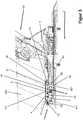
- FIG. 11 shows a sectional view of FIG Figure 2 along or parallel to the braking device longitudinal direction L.
- the pedal 4 comprises a lug 42 with which the cross strut 73 can latch in order to secure the second climbing aid 7 in the rest position on the pedal 4.
- the locking element 6 is for the most part guided in the pedal 4 and follows the movements of the pedal 4.
- the locking element 6 comprises a first arm 61 or main arm which is substantially parallel to the surface 411 of the Contact area 41 runs.
- the first arm 61 has a free end 611 which rests against the cross strut 53 or the sleeve 10 of the functional element 5.
- a second arm 62 is formed, which in the exemplary embodiment protrudes essentially perpendicularly from the first arm 61 and at its free end 621 forms an engagement element 64 which, in the shown first position of the locking element 6, forms an Opening 66 reaches through so that the pedal 4 is free to move upwards away from the gliding board together with the locking element 6 when the gliding board is released from the shoe 200, for example in the event of a fall.
- the locking element 6 comprises a third arm 63, which serves as a support for a spring element or tensioning element 9, which moves the locking element 6 shown in the first position into the second position (see FIG Figure 9 ) biases.
- the pedal 4, or a contact surface for the spring element in or on the pedal 4, forms a further support for the spring element 9.
- the Figure 4 shows the heel block of the heel holder 100 in a release position in which the user can get out of the binding with the shoe 200.
- the braking device 1 corresponds to the braking device 1 of the above-described figures and comprises the pedal 4, the braking elements 3, the functional element 5 and the second climbing aid 7.
- the functional element 5 and the second climbing aid 7 are connected to the pedal 4 in the swivel joint D1, so that the functional element 5 and the second climbing aid 7 can be moved relative to the pedal 4 from the position shown.
- the now unloaded pedal 4 has been moved upward by a known mechanism in the direction away from an upper side of the sliding board, at the same time the braking elements 3 have been moved in the opposite direction.
- the braking device 1 or the mechanism comprises a counter-locking element 65 with an opening 66 in which the braking device 1 can be locked by means of the locking element 6 when the gliding board with the heel holder 100 and the braking device 1 is used in touring mode.
- the Figure 5 shows a side view of the Figure 4 .
- the second arm 62 of the locking element 6 with the engagement element 64, with which the braking device can be locked for use in touring mode, can be clearly seen.
- FIG. 11 shows a sectional view of FIG Figure 5 .
- the braking device 1 comprises the functional element 5 with the crossbar 53 and the sleeve 10.
- the second climbing aid 7 is secured against unintentional loosening with the cross brace 73 on a nose 42 encompassed by the pedal 4.
- the functional element 5 and the second climbing aid 7 are connected to the pedal in the swivel joint D1.
- the locking element 6 rests with the free end 611 of the first arm 61 on the sleeve 10 of the functional element 5.
- the tensioning element 9 biases the locking element 6 in the direction away from the heel holder 100, so that the locking element 6, when it can move freely, from the first position shown by the tensioning element 9 into the position shown in FIG Figure 9 second position shown can be moved.
- the Figure 7 shows the heel holder 100 and the braking device 1, which is now secured in touring mode, so that the relieved pedal 4 is no longer in the position in FIG Figure 4 position shown can move.
- the functional element 5 has been moved from the first position it occupies in all the preceding figures into a second position, so that the sleeve 10 is now arranged above the pedal 4 and above the contact surface 41.
- the cross strut 53 or the sleeve 10 can, unlike in the exemplary embodiment, rest in the second position on the upper side 411 of the contact area.
- the functional element forms a first ascent or walking aid, with a height compensation of greater than or equal to 0 ° to approximately 1 °, preferably up to approximately 2 ° to 3 °.
- the front end 611 of the first arm 61 of the locking element 6 now protrudes further from the pedal 4, which means that the tensioning device 9 has moved the locking element 6 into the second position, in which the engagement element 64 secures the braking device 1 in the opening 66 .
- the position of the second climbing aid 7 is unchanged.
- the Figure 8 show the Figure 7 in a side view with an indicated shoe 200, which stands with a rear sole area on the functional element 5.
- the cross strut 53 of the functional element 5 or the sleeve 10 does not rest on the surface 411 of the contact surface 41, but is arranged above the surface 411 so that the cross strut 53 and / or the sleeve 10 rotate can, if a distance between the shoe 200 and the heel holder 100 changes for a short time, for example due to a flexing of the sliding board.
- the shoe 200 is now arranged further forward on the gliding board than the heel holder 100. Since, as already described, the braking device 1 and the heel holder 100 are connected together in the same connection with the gliding board, this means that the shoe 200 has to move relative to the gliding board moved forward. This means that the gliding board binding has a toe piece, not shown, which can hold the front end of the shoe 200 in two different shoe holding positions, a rear shoe holding position for downhill and a different front shoe holding position for touring or walking. Compared to the in Figure 2 As seen in the longitudinal direction L of the braking device, the shoe 200 is thus further forward, so that contact of the shoe 200 with the heel block of the heel holder 100 is avoided.
- the first arm 61 of the locking element 6 has an elongated hole 67 in a front area through which the axis of rotation D1 extends so that the locking element 6 can be moved linearly relative to the axis of rotation.
- FIG. 11 shows a sectional view of FIG Figure 8 . It can be clearly seen here that the engagement element 64 of the locking element 6 reaches through the opening 66 and has been moved away from the heel holder 100 by the tensioning element 9, so that the second arm 62 of the locking element 6 can no longer be moved vertically, thereby triggering it the braking device 1 is safely prevented.
- the starting position for locking the braking device is in Figure 5 shown.
- the functional element 5 is now pivoted from the first position into the second position.
- the pedal 4 can be pressed onto the sliding board by hand or is preferably pressed onto the sliding board when the shoe 200 is lowered. Since the engaging element 64 has already been moved by the tensioning element 9 into its end position in which it can no longer pass through the opening 66, it is shaped at the free end 621 of the second arm 62 in such a way that it moves downward through the opening edge against the Force of the tensioning element 9 is moved in the direction of the heel holder 100 until it can be pressed through the opening 66.
- the locking element 6 After penetrating the opening 66, the locking element 6 is automatically returned to the, in the, by the clamping element 9 Figure 9 shown locking position moved.
- the functional element 5 To open this lock, the functional element 5 is moved from the shown second position back into the first position. The functional element 5 presses the front end 611 of the first arm 61 of the locking element 6 in the direction of the heel holder 100 so that the engagement element 64 is arranged relative to the opening 66 such that it can move through the opening 66 again. This unlocks the braking device 1 and the pedal 4 moves away from the sliding board surface.
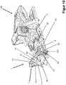
- the Figure 10 shows the braking device 1, in which the second climbing aid 7 has been moved into the active position and, in the exemplary embodiment shown, forms a height compensation of approximately 10 °.
- the amount of height compensation depends on the length of the connecting arms 71, 72 and the shape of the cross strut 73, which define a contact point or a contact line for the shoe 200.
- a latching element can be formed on the pedal 4, for example in the form of a partial sphere, which the latching finger or stop 722 must overcome before it comes to rest against the stop 21. This can prevent that the second climbing aid 7 is moved from the active position shown solely by gravity and is thereby pressed into the rest position when the shoe (200) is lowered onto the gliding board.
- Other known solutions that adequately solve this problem are encompassed by the invention.
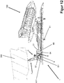
- FIG. 11 shows a sectional view of FIG Figure 11 .
Landscapes
- Footwear And Its Accessory, Manufacturing Method And Apparatuses (AREA)
- Braking Elements And Transmission Devices (AREA)
- Handcart (AREA)
- Braking Arrangements (AREA)
Applications Claiming Priority (1)
| Application Number | Priority Date | Filing Date | Title |
|---|---|---|---|
| DE102019108350.8A DE102019108350A1 (de) | 2019-03-29 | 2019-03-29 | Bremsvorrichtung |
Publications (1)
| Publication Number | Publication Date |
|---|---|
| EP3714952A1 true EP3714952A1 (fr) | 2020-09-30 |
Family
ID=68424820
Family Applications (2)
| Application Number | Title | Priority Date | Filing Date |
|---|---|---|---|
| EP19206528.2A Active EP3714951B1 (fr) | 2019-03-29 | 2019-10-31 | Fixation de ski |
| EP20164734.4A Pending EP3714952A1 (fr) | 2019-03-29 | 2020-03-20 | Dispositif de freinage |
Family Applications Before (1)
| Application Number | Title | Priority Date | Filing Date |
|---|---|---|---|
| EP19206528.2A Active EP3714951B1 (fr) | 2019-03-29 | 2019-10-31 | Fixation de ski |
Country Status (3)
| Country | Link |
|---|---|
| US (1) | US11154764B2 (fr) |
| EP (2) | EP3714951B1 (fr) |
| DE (1) | DE102019108350A1 (fr) |
Families Citing this family (1)
| Publication number | Priority date | Publication date | Assignee | Title |
|---|---|---|---|---|
| FR3141075B1 (fr) * | 2022-10-21 | 2025-10-17 | Rossignol Sa | Dispositif de freinage pour une planche de glisse |
Citations (4)
| Publication number | Priority date | Publication date | Assignee | Title |
|---|---|---|---|---|
| US20170056755A1 (en) * | 2015-08-27 | 2017-03-02 | Salomon S.A.S. | Braking device for a binding for a gliding board |
| EP3195906A1 (fr) * | 2016-01-22 | 2017-07-26 | Fritschi AG - Swiss Bindings | Talonniere ayant une configuration de marche |
| EP3437703A1 (fr) * | 2017-07-31 | 2019-02-06 | Skis Rossignol | Dispositif de freinage pour ski de randonnee |
| US20190070483A1 (en) * | 2016-02-17 | 2019-03-07 | Skis Rossignol | Holding element for a ski boot with a tiltable fitting pedal |
Family Cites Families (55)
| Publication number | Priority date | Publication date | Assignee | Title |
|---|---|---|---|---|
| DE2906726A1 (de) * | 1979-02-21 | 1980-10-23 | Marker Hannes | Fersenstrammer fuer sicherheits-skibindungen |
| AT368018B (de) * | 1979-10-25 | 1982-08-25 | Tyrolia Freizeitgeraete | Skibremse |
| DE3048175A1 (de) * | 1980-12-19 | 1982-07-22 | Heinrich Wunder GmbH & Co KG, 8060 Dachau | Tourenbindung mit skistopper |
| DE3110743A1 (de) * | 1981-03-19 | 1982-10-07 | Hannes Marker Sicherheits-Skibindungen GmbH & Co KG, 8100 Garmisch-Partenkirchen | Skistopper |
| DE3265951D1 (en) * | 1981-03-27 | 1985-10-10 | Tmc Corp | Ski brake |
| DE3116039A1 (de) * | 1981-04-22 | 1983-10-06 | Marker Patentverwertungs Gmbh | Skistopper |
| DE3131917C2 (de) * | 1981-08-12 | 1995-07-13 | Marker Int | Fersenstrammer für eine Skibindung mit integrierter Skibremse |
| AT372007B (de) * | 1981-09-18 | 1983-08-25 | Tyrolia Freizeitgeraete | Skibremse |
| DE3140819A1 (de) * | 1981-10-13 | 1983-04-21 | ess GmbH Skibindungen, 8978 Burgberg | Skibremse |
| DE3145646A1 (de) * | 1981-11-17 | 1983-05-26 | Marker Patentverwertungsgesellschaft mbH, 6340 Baar | Skistopper |
| FR2541124A1 (fr) * | 1983-02-23 | 1984-08-24 | Salomon & Fils F | Dispositif de verrouillage pour frein de ski |
| FR2542624B1 (fr) * | 1983-03-17 | 1985-06-28 | Look Sa | Frein a ski |
| FR2596287B2 (fr) * | 1985-07-26 | 1988-11-04 | Look Sa | Frein a ski |
| AT384554B (de) * | 1986-06-03 | 1987-12-10 | Tyrolia Freizeitgeraete | Skibremse |
| FR2607712B1 (fr) * | 1986-12-04 | 1989-11-03 | Salomon Sa | Frein de ski |
| FR2610206B1 (fr) * | 1987-02-03 | 1989-02-10 | Salomon Sa | Frein de ski associe a une fixation de ski alpin, couramment appelee talonniere |
| FR2631555B1 (fr) * | 1988-05-18 | 1990-08-17 | Salomon Sa | Frein de ski |
| DE3837379C2 (de) * | 1988-11-03 | 1997-10-23 | Marker Deutschland Gmbh | Skibremse |
| US5158317A (en) * | 1988-11-03 | 1992-10-27 | Marker Deutschland Gmbh | Ski brake assembly |
| AT394495B (de) * | 1989-09-01 | 1992-04-10 | Tyrolia Freizeitgeraete | Skibremse |
| ATE123233T1 (de) * | 1989-12-15 | 1995-06-15 | Salomon Sa | Sicherheitsskibindung. |
| DE4027712A1 (de) * | 1990-08-31 | 1992-03-05 | Look Sa | Skibremse |
| IT1251777B (it) * | 1991-11-08 | 1995-05-24 | Nordica Spa | Talloniera per attacchi da sci con mezzi di riarmo automatico |
| US5642897A (en) * | 1992-02-18 | 1997-07-01 | Salomon S.A. | Ski brake and device for modifying the natural pressure distribution of a ski over its sliding surface and a ski equipped therewith |
| FR2687326B1 (fr) * | 1992-02-18 | 1995-09-29 | Salomon Sa | Dispositif visant a modifier la repartition naturelle d'un ski sur sa surface de glisse, et ski equipe d'un tel dispositif. |
| FR2687325B1 (fr) * | 1992-02-18 | 1995-10-27 | Salomon Sa | Dispositif visant a modifier la repartition naturelle d'un ski sur sa surface de glisse, et ski equipe d'un tel dispositif. |
| FR2692804B1 (fr) * | 1992-06-30 | 1994-09-16 | Salomon Sa | Fixation de ski alpin. |
| FR2707512B1 (fr) * | 1993-07-16 | 1995-09-29 | Salomon Sa | Frein de ski. |
| AT410757B (de) * | 1993-12-10 | 2003-07-25 | Tyrolia Freizeitgeraete | Skibremse |
| FR2713945B1 (fr) * | 1993-12-17 | 1996-03-29 | Salomon Sa | Dispositif interface entre un ski et des éléments de fixation. |
| AT409934B (de) * | 1994-01-28 | 2002-12-27 | Varpat Patentverwertung | Bremsvorrichtung für einen schi |
| FR2741275B1 (fr) * | 1995-11-21 | 1998-01-23 | Look Fixations Sa | Fixation de ski equipee d'un frein demontable |
| JPH10314364A (ja) * | 1997-05-16 | 1998-12-02 | Shinku:Kk | スノーボード用ストッパー |
| FR2766380B1 (fr) * | 1997-07-22 | 1999-10-08 | Look Fixations Sa | Talonniere de fixation de ski |
| US6623027B1 (en) * | 1998-06-15 | 2003-09-23 | Bryce Wheeler | Release binding and brake for telemark and cross-country skis |
| FR2779971B1 (fr) * | 1998-06-19 | 2000-08-18 | Look Fixations Sa | Element de fixation de ski alpin equipe d'un frein demontable |
| FR2788991B1 (fr) * | 1999-02-02 | 2001-04-06 | Look Fixations Sa | Frein pour ski |
| US6390491B1 (en) * | 1999-05-19 | 2002-05-21 | Lemna J. Hunter | Downhill ski with integrated binding/traction device |
| US6293576B1 (en) * | 1999-05-19 | 2001-09-25 | Mechanical Solutions, Inc. | Downhill ski with traction device |
| FR2804338B1 (fr) * | 2000-02-02 | 2002-03-08 | Look Fixations Sa | Fixation de ski a frein demontable |
| US6769711B1 (en) * | 2000-08-10 | 2004-08-03 | Ralph M. Martin | Gas powered backwards release ski binding |
| US6659494B1 (en) * | 2000-08-10 | 2003-12-09 | Ralph M. Martin | Backwards release ski binding on a pivot plate mount |
| US7207591B2 (en) * | 2001-05-08 | 2007-04-24 | Rottefella As | Ski binding |
| US6877759B2 (en) * | 2002-08-27 | 2005-04-12 | Louis Dandurand | Ski binding |
| AT500306B1 (de) * | 2003-08-06 | 2008-09-15 | Atomic Austria Gmbh | Bremsvorrichtung für einen schi |
| FR2886863B1 (fr) * | 2005-06-09 | 2008-05-23 | Look Fixations Sa Sa | Dispositif de freinage pour planche de glisse de largeur reglable |
| US7458598B2 (en) * | 2005-12-05 | 2008-12-02 | Jeffrey Giffin | Telemark binding with releasable riser plate assembly |
| WO2012024809A1 (fr) * | 2010-08-27 | 2012-03-01 | Fritschi Ag - Swiss Bindings | Fixation de ski de randonnée à talonnière comportant une zone de glissement dynamique |
| DE102012207959B4 (de) * | 2012-05-11 | 2020-11-12 | Fritz Barthel | Vordereinheit einer Gleitbrettbindung und Gleitbrettbindung |
| US8827302B2 (en) * | 2012-09-11 | 2014-09-09 | Fritschi Ag-Swiss Bindings | Automatic heel unit for a ski binding |
| DE102013201725B4 (de) * | 2013-02-01 | 2026-01-29 | Marker Deutschland Gmbh | Fersenhalter mit Verriegelungshebel |
| EP2813268A1 (fr) * | 2013-06-12 | 2014-12-17 | Fritschi AG - Swiss Bindings | Automate avant |
| EP2929919B1 (fr) * | 2014-04-09 | 2018-05-30 | Salomon S.A.S. | Fixation de ski |
| US10463946B2 (en) * | 2017-06-07 | 2019-11-05 | G3 Genuine Guide Gear Inc. | Touring binding heel unit |
| US10315099B2 (en) * | 2017-10-31 | 2019-06-11 | G3 Genuine Guide Gear Inc. | Lightweight touring binding heel unit |
-
2019
- 2019-03-29 DE DE102019108350.8A patent/DE102019108350A1/de active Pending
- 2019-10-31 EP EP19206528.2A patent/EP3714951B1/fr active Active
-
2020
- 2020-03-20 EP EP20164734.4A patent/EP3714952A1/fr active Pending
- 2020-03-26 US US16/830,712 patent/US11154764B2/en active Active
Patent Citations (4)
| Publication number | Priority date | Publication date | Assignee | Title |
|---|---|---|---|---|
| US20170056755A1 (en) * | 2015-08-27 | 2017-03-02 | Salomon S.A.S. | Braking device for a binding for a gliding board |
| EP3195906A1 (fr) * | 2016-01-22 | 2017-07-26 | Fritschi AG - Swiss Bindings | Talonniere ayant une configuration de marche |
| US20190070483A1 (en) * | 2016-02-17 | 2019-03-07 | Skis Rossignol | Holding element for a ski boot with a tiltable fitting pedal |
| EP3437703A1 (fr) * | 2017-07-31 | 2019-02-06 | Skis Rossignol | Dispositif de freinage pour ski de randonnee |
Also Published As
| Publication number | Publication date |
|---|---|
| US20200306615A1 (en) | 2020-10-01 |
| DE102019108350A1 (de) | 2020-10-01 |
| EP3714951B1 (fr) | 2021-12-01 |
| US11154764B2 (en) | 2021-10-26 |
| EP3714951A1 (fr) | 2020-09-30 |
Similar Documents
| Publication | Publication Date | Title |
|---|---|---|
| EP2319596B1 (fr) | Mâchoire avant pour une fixation de ski de fond et chaussure de ski pour une fixation de ski de fond | |
| DE202009019128U1 (de) | Zeheneinheit für Tourenskibindung | |
| DE19635250A1 (de) | Automatische Befestigungsvorrichtung | |
| DE102012208915B4 (de) | Ferseneinheit mit Steighilfe und Bremsanordnung | |
| EP3566754B1 (fr) | Butée avant de fixation de ski | |
| DE9421380U1 (de) | Snowboardbindung | |
| EP2626116A1 (fr) | Unité avant pour la fixation d'une planche de glisse | |
| EP3928842B1 (fr) | Unité avant pour une fixation de randonnée | |
| AT171U1 (de) | Kombination, bestehend aus einem snowboardschuh und einer snowboardbindung | |
| DE69504518T2 (de) | Bindung für einen schuh auf einem snowboard | |
| EP3974039A1 (fr) | Agencement de freinage pour une fixation de randonnée | |
| EP1559455B1 (fr) | Fixation adaptée au ski de randonnée | |
| DE2638690A1 (de) | Bindung zum halten eines schuhes auf einer unterlage | |
| EP0247104B1 (fr) | Fixation de ski pour ski de fond ou de tourisme | |
| DE69401171T2 (de) | Bindungselement für einen alpinen Ski | |
| EP0581802B1 (fr) | Chaussure de sport | |
| DE2429719A1 (de) | Fangeinrichtung fuer skier | |
| EP3714952A1 (fr) | Dispositif de freinage | |
| DE4424737C1 (de) | Snowboardbindung | |
| EP4374939A1 (fr) | Butée avant avec mâchoire abaissable | |
| EP2821114B1 (fr) | Système de fixation de sécurité | |
| DE102012214002B4 (de) | Touring-Ferse mit Hilfshebel | |
| DE3245668C2 (de) | Auslösende Langlaufbindung | |
| DE3227232C2 (de) | Fersenhalterung für eine Langlaufskibindung | |
| AT410176B (de) | Bindungskonstruktion |
Legal Events
| Date | Code | Title | Description |
|---|---|---|---|
| PUAI | Public reference made under article 153(3) epc to a published international application that has entered the european phase |
Free format text: ORIGINAL CODE: 0009012 |
|
| STAA | Information on the status of an ep patent application or granted ep patent |
Free format text: STATUS: THE APPLICATION HAS BEEN PUBLISHED |
|
| AK | Designated contracting states |
Kind code of ref document: A1 Designated state(s): AL AT BE BG CH CY CZ DE DK EE ES FI FR GB GR HR HU IE IS IT LI LT LU LV MC MK MT NL NO PL PT RO RS SE SI SK SM TR |
|
| AX | Request for extension of the european patent |
Extension state: BA ME |
|
| STAA | Information on the status of an ep patent application or granted ep patent |
Free format text: STATUS: REQUEST FOR EXAMINATION WAS MADE |
|
| 17P | Request for examination filed |
Effective date: 20201118 |
|
| RBV | Designated contracting states (corrected) |
Designated state(s): AL AT BE BG CH CY CZ DE DK EE ES FI FR GB GR HR HU IE IS IT LI LT LU LV MC MK MT NL NO PL PT RO RS SE SI SK SM TR |
|
| STAA | Information on the status of an ep patent application or granted ep patent |
Free format text: STATUS: EXAMINATION IS IN PROGRESS |
|
| 17Q | First examination report despatched |
Effective date: 20210614 |