EP3715073A1 - Scie - Google Patents
Scie Download PDFInfo
- Publication number
- EP3715073A1 EP3715073A1 EP20156062.0A EP20156062A EP3715073A1 EP 3715073 A1 EP3715073 A1 EP 3715073A1 EP 20156062 A EP20156062 A EP 20156062A EP 3715073 A1 EP3715073 A1 EP 3715073A1
- Authority
- EP
- European Patent Office
- Prior art keywords
- carrier
- line system
- protective
- work surface
- saw
- Prior art date
- Legal status (The legal status is an assumption and is not a legal conclusion. Google has not performed a legal analysis and makes no representation as to the accuracy of the status listed.)
- Granted
Links
Images


Classifications
-
- B—PERFORMING OPERATIONS; TRANSPORTING
- B23—MACHINE TOOLS; METAL-WORKING NOT OTHERWISE PROVIDED FOR
- B23Q—DETAILS, COMPONENTS, OR ACCESSORIES FOR MACHINE TOOLS, e.g. ARRANGEMENTS FOR COPYING OR CONTROLLING; MACHINE TOOLS IN GENERAL CHARACTERISED BY THE CONSTRUCTION OF PARTICULAR DETAILS OR COMPONENTS; COMBINATIONS OR ASSOCIATIONS OF METAL-WORKING MACHINES, NOT DIRECTED TO A PARTICULAR RESULT
- B23Q11/00—Accessories fitted to machine tools for keeping tools or parts of the machine in good working condition or for cooling work; Safety devices specially combined with or arranged in, or specially adapted for use in connection with, machine tools
- B23Q11/06—Safety devices for circular cutters
-
- B—PERFORMING OPERATIONS; TRANSPORTING
- B27—WORKING OR PRESERVING WOOD OR SIMILAR MATERIAL; NAILING OR STAPLING MACHINES IN GENERAL
- B27G—ACCESSORY MACHINES OR APPARATUS FOR WORKING WOOD OR SIMILAR MATERIALS; TOOLS FOR WORKING WOOD OR SIMILAR MATERIALS; SAFETY DEVICES FOR WOOD WORKING MACHINES OR TOOLS
- B27G19/00—Safety guards or devices specially adapted for wood saws; Auxiliary devices facilitating proper operation of wood saws
- B27G19/02—Safety guards or devices specially adapted for wood saws; Auxiliary devices facilitating proper operation of wood saws for circular saws
- B27G19/025—Safety guards or devices specially adapted for wood saws; Auxiliary devices facilitating proper operation of wood saws for circular saws with guards for tool
-
- B—PERFORMING OPERATIONS; TRANSPORTING
- B27—WORKING OR PRESERVING WOOD OR SIMILAR MATERIAL; NAILING OR STAPLING MACHINES IN GENERAL
- B27G—ACCESSORY MACHINES OR APPARATUS FOR WORKING WOOD OR SIMILAR MATERIALS; TOOLS FOR WORKING WOOD OR SIMILAR MATERIALS; SAFETY DEVICES FOR WOOD WORKING MACHINES OR TOOLS
- B27G19/00—Safety guards or devices specially adapted for wood saws; Auxiliary devices facilitating proper operation of wood saws
- B27G19/08—Accessories for keeping open the saw kerf, e.g. riving knives or wedge plates
Definitions
- the invention relates to an underfloor pull saw or table saw with a work table which provides a work surface for supporting workpieces to be processed, a saw blade which is partially under the work surface and protrudes upwards at least during the sawing operation beyond the work surface, and one under the work surface arranged drive for the saw blade, which is designed to set the saw blade in rotation during the sawing operation, a carrier which is supported below the work surface on a holder and protrudes upwards beyond the work surface, and a protective cover carried by the carrier, which is designed to protect against intervention in the saw blade in a protective position, with at least one electrical or electronic functional unit being integrated into the protective cover, with a base unit for the functional unit being arranged below the work surface, and with the functional unit above there is a supply and / or communication link connected to the base unit.
- the use of the holder or riving knife as a current-carrying component is also problematic in terms of occupational safety if no electrical insulation measures are taken. Such measures would mean a higher production cost and would also be disadvantageous insofar as the riving knife must not exceed a certain thickness due to its function.
- the object of the invention is to improve a saw of the type mentioned at the outset such that the protective cover can be used in a simple and reliable manner for the integration of basically any functional units.
- the supply and / or communication path via which the electrical or electronic functional unit integrated in the protective cover with the one below the work surface Base unit is connected, comprises an electrical line system, and that this electrical line system is integrated into the carrier.
- the invention consequently takes a different route than that mentioned above DE 32 19 901 A1 provided by the carrier for the protective cover is not used as an electrical conductor itself, but by integrating the electrical line system into the carrier.
- This has hitherto been considered unrealizable, since in a saw of the type in question here, the carrier of a protective cover provided for the saw blade must not be thicker than the saw blade and thus supposedly cannot provide any installation space.
- the inventive integration of the electrical line system in the carrier it is not necessary to arrange devices for energy supply or for communication that require relevant installation space in addition to the functional unit within the protective cover. Rather, such base units can be placed below the work surface where there is enough space available.
- the integration of the electrical line system in the carrier also opens up contacting options that allow both simple adjustment of the carrier relative to the holder and removal of the carrier from the holder and removal of the protective cover from the carrier without the need for electrical contacts to be loosened in a cumbersome manner would need to be restored later.
- the carrier can either be formed by a riving knife or provided in addition to a riving knife. According to the invention, it is consequently possible, but not mandatory, to use a riving knife of the saw for the integration of the line system. Depending on the specific design of the saw, in addition to one Riving knife a separate carrier for the protective cover can be provided. In addition, it is also possible to use both components - that is, both the riving knife and an additionally provided carrier for the protective cover - for the integration of the electrical line system.
- the line system according to the invention does not need to extend over the entire length of the carrier. It is sufficient if the line system extends along part of the carrier.
- the integration of the line system in the carrier ensures that the functional unit integrated in the protective cover can be connected to the area below the work surface, i.e. the line system extends at least along a section of the carrier which extends from below the work surface to above the work surface.
- a recess is formed in the carrier for the line system, in which the line system is accommodated.
- the recess can only be formed on one side of the carrier. Alternatively, it is possible to form several depressions on different sides of the carrier. For example, two recesses for the line system can be present on opposite carrier sides.
- the recess is preferably designed as a groove. This is preferably a shallow groove, the width of which is a multiple of the groove depth.
- the recess has been produced by a milling process.
- a milling process enables a comparatively simple and inexpensive manufacturing process.
- the carrier is preferably designed as a flat part, the recess being formed in a flat side of the carrier.
- the line system accommodated in the recess ends flush with the outside of the carrier or jumps back with respect to the outside.
- the line system is thereby well protected against external mechanical influences without additional measures having to be taken to cover or encapsulate the line system.
- the line system can comprise a plurality of individual lines that run in parallel and are insulated from one another.
- the line system comprises at least one conductor track.
- the line system is a component which is produced separately from the carrier and which has been integrated into the carrier after its production.
- the manufacture of the support of the saw, in particular the riving knife, is particularly simple as a result.
- a separately manufactured line system, which only needs to be assembled, can be obtained particularly cost-effectively from manufacturers who specialize in this area.
- the line system is preferably designed to be flexible when it is not yet integrated into the carrier. It is particularly advantageous here that the line system does not need to have a high inherent rigidity. As a result, it can be manufactured with a very small thickness, so that very little installation space, in particular only a very shallow receiving groove, is required on or in the carrier in order to integrate the flexible line system into the carrier. In the integrated state the flexible line system is protected from deformation due to the rigidity provided by the carrier itself.
- the line system can have a multilayer structure which comprises at least one electrically insulating carrier layer and at least one conductor track applied to the carrier layer.
- the multilayer structure can additionally have a fastening layer, preferably an adhesive layer, which is provided on the side of the carrier layer opposite the conductor track and by means of which the line system is fastened to the carrier.
- a fastening layer preferably an adhesive layer, which is provided on the side of the carrier layer opposite the conductor track and by means of which the line system is fastened to the carrier.
- An additional fastening layer in particular in the form of an adhesive layer, enables simple and secure assembly of the line system on the carrier.
- the conductor track can be provided with a surface treatment at least in some areas, in particular in at least one contact area.
- This surface treatment can preferably be gold plating.
- the formation of disadvantageous oxide layers on the conductor track can be reliably prevented in this way.
- the carrier is preferably made of metal, the line system being electrically insulated from the carrier.
- the electrical insulation can e.g. can be ensured by a carrier layer of a multilayer structure of the line system.
- At least one contact area for the line system is provided on the carrier, via which contact area the line system is connected to a mating contact that does not belong to the carrier.
- the contact area is preferably formed by the line system and in particular by an area of at least one conductor track of the line system.
- the Contact area can have several individual contacts, in particular one contact area for each individual line, for example for each individual conductor track.
- Two contact areas are preferably provided on the carrier, which are assigned to two mating contacts that are located on different sides of the work surface.
- Each contact area can have a plurality of individual contacts, each of which is assigned an individual counter-contact of the respective counter-contact that does not belong to the carrier.
- a mating contact can be arranged on the protective cover and connected to the functional unit integrated in the protective cover.
- a mating contact can be arranged below the work surface and connected to the base unit.
- the electrical connection between the or each contact area and the associated mating contact can be released. It can thereby be achieved that, for example, the carrier can be easily removed from the holder or the protective cover can be easily removed from the carrier and the electrical connection can be released at the same time.
- a mechanical connection can be provided between the carrier and the or each counter-contact, this mechanical connection being releasable.
- the line system can comprise several parallel, mutually insulated individual lines, in particular individual conductor tracks, the individual lines each having at least one contact area, the contact areas of the individual lines are arranged in close proximity to one another and at the same time can be connected to respective mating contacts.
- the carrier with the contact area is inserted into the mating contact or pushed onto the mating contact.
- Such a type of connection enables the electrical contact to be made in a particularly simple and reliable manner at the same time as a mechanical connection between the carrier and a component having the mating contact.
- the mating contact preferably comprises a sliding contact.
- a sliding contact allows the two components to be adjusted relative to one another without loosening the electrical contact. This type of contact is particularly advantageous if, according to a preferred embodiment of the invention, the line system comprises one or more conductor tracks.
- the electrical connection between the or each contact area and the respective mating contact is designed in such a way that this electrical connection allows mechanical adjustment between the contact area and mating contact while maintaining the effectiveness of the electrical contact.
- Such an electrical connection can in particular be implemented by the interaction of one or more conductor tracks, each with a sliding contact.
- This type of contact represents a preferred embodiment of the invention.
- the carrier together with the protective cover, can be adjusted in height relative to the holder relative to the work surface.
- the protective cover can be adjustable relative to the wearer.
- An alternative embodiment is also possible in which the protective cover cannot be adjusted relative to the carrier.
- the protective cover is preferably removable from the carrier.
- a through-opening in particular a slot-shaped, through opening is formed in the work surface for the carrier, through which the carrier protrudes upwards beyond the work surface, the carrier being removable upwards through the through-opening.
- the functional unit integrated in the protective cover can comprise at least two different functional modules.
- One of the functional modules can be a sensor module which transmits measurement signals to the base unit, on the basis of which the base unit transmits control signals to the other functional module.
- the base unit is preferably designed for bidirectional communication with the functional unit via the line system.
- the base unit can be designed to supply the functional unit with power via at least one line of the line system and via the same Line to lead a unidirectional or bidirectional communication with the functional unit.
- the base unit for the functional unit which is arranged below the work surface, can comprise a power supply unit for supplying power to the functional unit and a control device for communication with the functional unit.
- a flow path leading from an inlet area to an outlet area for sawdust produced during the sawing operation is formed within the protective cover.
- a protective chamber separated from the flow path and / or a protective wall located in the flow path, at least partially transverse or oblique to the flow direction and / or a protective projection located in the flow path is provided in the protective cover for at least one component of the functional unit.
- components of the functional unit can be accommodated in the protective cover without the risk of these components being impaired or damaged in their function by the sawdust moving from the entry area to the exit area.
- a mating contact for the line system integrated in the carrier or a functional module of the functional unit can be arranged in a protective chamber.
- the protective cover can also have several protective chambers, for example one for a counter contact and one for a functional module, e.g. a light module.
- connection line of the functional unit can be routed through the flow path, for example, along a downstream rear side of a protective wall or a protective projection.
- a protective wall or a protective projection which is located inside the protective cover in a flow path for sawdust, can have a cross-sectional profile which is shaped in a flow-favorable manner.
- the protective cover can preferably be fastened to the carrier by clamping.
- a screw terminal for the carrier can be integrated into the protective cover.
- the screw terminal comprises two integral with the protective cover, e.g. each with a partial or half-shell of the protective cover, formed clamping sections, between which the carrier can be clamped, an actuating nut rotatable about an axis of rotation, an integrally formed on the one clamping section, circumferential around the axis of rotation, which can be acted upon by means of the actuating nut, around the To close or open screw terminal, ie in order to clamp or loosen the two clamping sections, and a connecting member which holds the other clamping section and the actuating nut at a predetermined axial distance.
- the clamping sections are biased in the closing direction by means of a spring element, i.e. in the direction of compressing the two clamping sections, the actuating nut being rotatable against the restoring force of the spring element in order to open the screw terminal.
- the threaded section is preferably effective over an angular range of less than 180 °. This makes it possible to provide two diametrically opposite thread sections.
- the threaded section is preferably designed as a run-on slope for at least one control section of the actuating nut.
- the actuating nut preferably has two diametrically opposite control sections which each act on one of two subsections of the threaded section.
- the carrier can preferably be inserted into the screw terminal.
- the carrier can be provided with a recess with which the carrier can be plugged onto a component of a clamping device integrated into the protective cover for the carrier.
- the recess in the carrier is preferably designed in such a way that the carrier can be suspended from a holder of the saw when it is not in use.
- the protective cover comprises a protective hood protecting against engagement with the saw blade from above and a side protection protecting against a lateral engagement with the saw blade, which is attached to the protective hood by means of a ball bearing, e.g. a deep groove ball bearing, is pivotably mounted.
- a ball bearing e.g. a deep groove ball bearing
- a plain bush bearing can in principle also be used.
- the side protection preferably comprises two side protection elements each attached to one of the two sides of the protective hood.
- the ball bearing is preferably permanently installed in the side protection and / or attached in a captive manner, in particular by overmolding. If a sliding bush bearing is provided, then this can comprise a separate sliding bush which is fastened to the protective hood and is designed in such a way that the side protection is held captive on the sliding bush and can be pivoted without jamming.
- the protective hood can be fastened to the carrier, in particular releasably, with the protective hood preferably not being adjustable relative to the carrier when fastened to the carrier.
- the side protection has at least one viewing opening penetrated by protective struts, the protective struts being inclined around to allow a view of the saw blade at an angle from the front.
- the protective struts can be sufficiently narrow and, in particular, spaced from one another in accordance with relevant safety regulations, in order to reliably prevent accidental intervention with a finger, and at the same time enable a good view of the work area due to the inclined position.
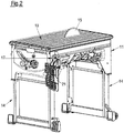
- the Fig. 1 and 2 show an underfloor pull saw as it is known with regard to its basic structure.
- the saw comprises a table with a frame 11 and two legs 14, which can be pivoted relative to the frame 11 between the illustrated unfolded working position and a folded-in transport position.
- the workpiece does not need to be moved through the saw blade 15, but, conversely, the entire work unit, which, among other things, the saw blade 15 and a drive located inside the frame under the work surface 13, through which the workpiece resting on the work surface 13 is moved.
- a slot-shaped opening for the saw blade 15 is provided in the work surface 13.
- a narrow riving knife 17 also extending through the mentioned slot opening carries a protective cover 21 and thus represents a carrier in the sense of the present invention.
- the protective cover 21 comprises a protective hood 53 protecting against engagement with the saw blade 15 from above and protective hood 53 against lateral engagement Side protection elements 55a, 55b, which - similar to applied wings - are articulated to the protective hood 53 in a freely movable manner and thus rest on the work surface 13 due to gravity when - as in FIG Fig. 1 - there is no workpiece.
- the drive for the saw blade 15 and the riving knife 17 are supported on a common holder which is located below the work surface 13.
- An in Fig. 1 and 2 not shown holder 19 (cf. Fig. 3 ) for the riving knife 17, which will be discussed in more detail below, can be moved with pivoting movements together with the saw blade 15 or its drive unit and with a height adjustment to adjust the cutting depth either independently of or in a suitable manner positively guided with the adjustment movement of the saw blade 15. This ensures that in every position of the saw blade 15 relative to the work surface 13, the protective cover 21 has a prescribed protective effect.
- the riving knife 17 can be removed from its holder 19 simply by pulling it off and removed upwards from the aforementioned slot opening. Also between the protective hood 53 and riving knife 17 there is a plug-in connection - additionally secured by a clamping device described in more detail elsewhere - which can be easily detached in order to be able to remove the protective hood 53 and thus the entire protective cover 21 from the riving knife 17.
- the riving knife 17 and the protective cover 21 can - like Fig. 2 shows - when not in use, can be hung on a hook attached to the side of the frame 11.
- so-called insert cuts or hidden cuts can be made in which the saw blade 15 only cuts into the underside of a workpiece resting on the work surface 13, but does not cut through the workpiece.
- Fig. 3 shows only the arrangement of protective cover 21, riving knife 17 and holder 19, into which the riving knife 17 is inserted on the side of the holder 19 facing away here.
- a special feature of the invention is that a functional unit comprising a light module, shown elsewhere, is integrated into the protective hood 53.
- the power supply for the light module is provided by a power supply unit 25 arranged in the frame 11 below the work surface 13, which serves as a base unit for the functional unit integrated in the protective hood 53.
- a supply line 25a in the form of a connection line leads from the power supply unit 25 to the holder 19, on which an electrical line system 27 integrated in the riving knife 17 is contacted in a manner described in more detail below.
- the protective hood 53 is also provided with a contact module 24, explained in more detail below, with which the line system 27 of the riving knife 17 is contacted in order to establish an electrical connection between the power supply 25 under the work surface 13 on the one hand and the one in the protective hood 53 and thus producing the light module located above the work surface 13 on the other hand.
- the riving knife 17 is not itself part of an electrical conductor, but rather serves to accommodate it.
- the presence of the riving knife 17 and in particular its mechanical stability are used according to the invention in order to be able to establish an electrical connection between a location below the work surface and a location on or in the protective cover located above the work surface in a simple and reliable manner.
- FIG. 4 and the Figure 5a and 5b with the individual sectional views show an embodiment of a riving knife 17 provided according to the invention with an electrical line system 27, the sectional views in FIG Figure 5a schematically and in Figure 5b are shown to scale.
- the riving knife 17 is made of metal and is provided on one of its flat sides with a flat groove 29 which has been produced by a milling process.
- the groove depth 29b is less than 1 mm, for example 0.3 to 0.4 mm.
- the line system 27 is a component produced separately from the riving knife 17, which in itself has a flexible multilayer structure.
- An adhesive layer 35 is located below an electrically insulating carrier layer 33.
- two conductor tracks 31a, 31b, each forming a single line, are applied to the carrier layer 33.
- the conductor tracks 31a, 31b are protected from external influences by a gold plating (not shown).
- This multilayer structure is so thin that it can be glued into the shallow groove 29 of the riving knife 17 without protruding, i. E. the conductor tracks 31a, 31b close flush with the flat side of the riving knife 17 or even jump back a little.
- the conductor tracks 31a, 31b each end as an extended individual contact 37a, 37b, which together form an upper contact area 37.
- the conductor tracks 31a, 31b each form a widened, elongated individual contact 29a, 29b, which together define a lower contact area 39 of the riving knife 17.
- the receiving groove 29 is widened accordingly.
- the receiving groove 29 of the riving knife has, for example, a width 29a of approximately 6.5 mm, the width e.g. can be in a range from 6 to 10mm. Depending on the respective application, the width can also be less than 6mm.
- a contact module 24 is integrated into the protective hood 53 (cf. Fig. 6 ), for which in one bowl the from two assembled partial shells formed protective hood 33 a protective chamber 49 is formed.
- the contact module 24 arranged in this protective chamber 49 is thus protected from sawdust flowing through the protective hood 53, which will be discussed in more detail elsewhere.
- the contact module 24 comprises a carrier part 24a on which two curved contact springs are attached, the individual counter-contacts 38a, 38b for the upper individual contacts 37a, 37b (cf. Fig. 4 and 5 ) of the riving knife 17.
- a cover part 24b serves as a hold-down device and insulation for the spring contacts 38a, 38b.
- the cover part 24b is pushed onto the carrier part 24a with these contact springs 38a, 38b in between.
- the contact module 24 assembled in this way is open on its underside, so that the upper contact area 37 of the riving knife 17 formed by the individual contacts 37a, 37b can be inserted.
- the contact between riving knife 17 and protective hood 53 thus takes place according to the principle of a sliding contact.
- connection line 23b is connected to the contact module 24, which is laid in the protective hood 53 and to the in Fig. 6 light module not shown leads.
- FIG. 7 shows an intermediate part 20a of the holder 19, which has a plug-in guide 20e with a centrally arranged web 20c which, when the riving knife 17 is inserted, is arranged between the two narrow end sections of the splitting wedge 17, which is fork-like in this end region.
- a receptacle 20d for the carrier part 26a of a contact module 26 is formed in the intermediate part 20a.
- two curved spring contacts are attached, which form individual mating contacts 40a, 40b for the lower individual contacts 39a, 39b of the riving knife 17 and thus a mating contact 40 for the lower contact area 39 of the riving knife 17.
- a cover part 26b is in turn plugged onto the carrier part 26a.
- a recess 20f surrounding the receptacle 20d is formed in the intermediate part 20a.
- the contact module 26 of the holder 19 is provided with openings 26c, through which the two spring contacts 40a, 40b protrude beyond the outer side of the cover part 26b facing the inserted riving knife 17 in the assembled state.
- the contact springs 40a, 40b are each in electrically conductive contact with the relevant contact area 39a, 39b on the facing flat side of one narrow end portion of the riving knife 17. Due to the elongated shape of the riving knife-side contact areas 39a, 39b can - for Height adjustment of the protective hood 53 carried by the riving knife 17 - the riving knife 17 can be moved while maintaining the electrical connection established by the described sliding contact in the intermediate part 20a.
- FIGS. 8 and 9 show the in Fig. 3 facing away side of the holder 19 with not yet contacted riving knife 17 only partially inserted into the intermediate part 20a.
- the cover part 26b and the mating contact 40 formed by the contact springs described above, which is on one side of the central web 20c, can be seen.
- a latching button 20b is formed on the intermediate part 20a, which is not connected to an outside on the for the electrical contact provided narrow end portion of the riving knife 17 formed locking groove 18 (cf. Fig. 4 ) cooperates as soon as the riving knife 17 is pushed in far enough.
- the ends of the locking groove 18 mark the maximum and the minimum insertion depth of the riving knife 17 on the holder 19 and thus noticeably indicate to the user that the riving knife 17 has reached the lowest and highest position and thus the protective cover 21 carried by the latter.
- the riving knife 17 can be inserted in a simple manner and in particular without tools from above through the slot opening formed in the working surface 13 of the saw and withdrawn upwards when not in use.
- the Figures 10, 11 and 12 show the mechanical coupling of the riving knife 17 to the protective hood 53.
- the wing-like side protection elements 55a which are pivotably attached to the side of the protective hood 53, are both from the mechanical coupling of the riving knife 17 to the protective hood 53 and from the electrical contact between the riving knife 17 and in the protective hood 53 housed contact module 24 independently.
- the riving knife 17 is provided at its upper, straight end adjacent to the upper contact area 37 formed by the individual contacts 37a, 37b with a recess 71 which is open to the straight side 17a of the riving knife 17 and, starting from this opening, widens essentially circularly .
- This undercut makes it possible to hang the riving knife 17 on the frame 11 when not in use, as shown in FIG Fig. 2 is shown.
- the recess 71 serves to position the riving knife 17 in a screw terminal which, among other things, has a connecting member 67 (cf. in particular Fig. 12 ) which extends through the recess 71 when the riving knife 17 is coupled to the protective hood 53.
- the screw clamp mentioned also comprises two clamping sections 61a, 61b, which are each formed in one piece on one of the two partial shells of the protective hood 53.
- the connecting member 67 oriented with its longitudinal axis perpendicular to the riving knife 17, engages behind with a flange 68a formed on a head 68 the in Fig. 12 right clamping section 61b, extends through the recess 71 of the riving knife 17 and the other clamping section 61a and is firmly connected at its free end to an actuating nut 63 in the axial direction.
- the connecting member 67 including head 68 and flange 68a and the actuating nut 63 can be rotated together about an axis of rotation 65.
- the actuating nut 63 is provided with two diametrically opposite projections 63a, 63b, which cooperate with threaded sections 66a, 66b, each designed as a ramp for the relevant continuation, in order, depending on the direction of rotation, of the actuating nut 63 about the axis of rotation 65, which with the Longitudinal axis of the connecting member 67 coincides, either to open or close the screw terminal.
- the compression spring 69 ensures the open position of the screw terminal, in which the riving knife 17 can be inserted and withdrawn.
- the two clamping sections 61a, 61b can be pressed together against the restoring force of the compression spring 69 in order to close the screw terminal.
- the in Fig. 12 biases the two clamping sections 61a, 61b in the closing direction of the screw terminal by means of the compression spring 69, i.e. it is the compression spring 69 which compresses the two clamping sections 61a, 61b by pressing the actuating nut 63 and thus the flange 68a on the head 68 in Fig. 12 to the left and thus presses the clamp portion 61b against the clamp portion 61a which is urged to the right by the compression spring 69.
- the compression spring 69 i.e. it is the compression spring 69 which compresses the two clamping sections 61a, 61b by pressing the actuating nut 63 and thus the flange 68a on the head 68 in Fig. 12 to the left and thus presses the clamp portion 61b against the clamp portion 61a which is urged to the right by the compression spring 69.
- the screw terminal is then opened by rotating the actuating nut 63 through an angular range of approximately 90 ° and at the same time moving the actuating nut 63 together with the connecting element 67 and thus the head 68 and flange 68a to the right in Fig. 12 and at the same time against the restoring force of the compression spring 69.
- This movement to the right is possible because when the actuating nut 63 is turned, its extensions 63a, 63b on the ramp-like threaded sections 66a, 66b can come down, here to the right.
- the light module which in this exemplary embodiment forms a functional module 23a of the functional unit 23, is arranged in the front region of the protective hood 53, of which the open side of the one partial shell is shown here.
- the connecting line 23b connects the light module 23a to the contact module 24 arranged in the rear area.
- the screw terminal explained above, of which the actuating nut 63 is shown here, is located adjacent to the contact module 24.
- Both the contact module 24 and the light module 23a are each arranged in a protective chamber 49 of the protective hood 53.
- Fig. 14 shows the protective hood 53 in the state placed on the riving knife 17.
- the riving knife 17 is pushed so far into the intermediate part 20a of the holder 19 that the latching button 20b with the one narrow end portion of the fork-shaped lower end of the riving knife 17, namely with the in Fig. 4 locking groove 18 shown can interact.
- the other narrow end section is connected to the in Figures 8 and 9 shown contact module 40 of the holder 19 is electrically connected.
- the central web 20c is located between the two narrow end sections of the riving knife 17.
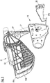
- a suction device can be connected to the protective hood 53, specifically to a connecting piece 53a formed in the rear area, which forms an exit area for chips sucked in via a lower entry area 41.
- a flow path 45 consequently runs through the protective hood 53 between the inlet area 41 and the outlet area 43.
- a protective measure is also provided for the connection line 23b.
- a flow-optimized protective projection 51 is formed, which is positioned in front of the section of the connection line 23b that is to be protected and crosses the flow path 45 (see also FIG Fig. 14 ) and thus effectively acts as a shield for this line section to protect it from the chips flowing through it.
- the protective projection 51 also serves as a screwing point for the other partial shell of the protective hood 53.
- Fig. 16 illustrates the pivotable attachment of the two wing-like side protection elements 55a, 55b to the protective hood 53.
- the pivot axis is each defined by a ball bearing 57 on which the respective protection element 55a or 55b is pivotably mounted by means of an opening 56b.
- the ball bearing 57 is placed on a receptacle 60 and secured by a screw 58.
- a receptacle 60 is also formed on the relevant outer side of the protective hood 53 for a pivoting guide and cooperates with a guide slot 56a of the relevant side protective element 55a or 55b.
- This pivoting guide comprises a slider 73, which can slide guided along the guide slot 56a on the relevant side protection element 55a or 55b and is secured by a screw 58 which is screwed into the receptacle 60 in the assembled state.
- the slider 73 can, for example be made of a plastic with a relatively low coefficient of friction, such as polyoxymethylene.
- Both the pivot bearing and the pivot guide are designed in such a way that the protective elements 55a, 55b are not clamped in, i.e. no clamping forces are effective, and that the frictional forces are minimized through the choice of a respective storage concept and / or material, e.g. -
- a ball bearing for example a deep groove ball bearing
- a sliding guide made of a material with a low coefficient of friction for the pivot guide. This ensures that the side protection elements 55a, 55b can be pivoted with extremely low friction, i.e. that only very small forces are required for pivoting.
- Viewing openings 59 of the side protection elements 55a, 55b interspersed with sufficiently closely spaced protective struts 59a ensure a good view of the work area from the front, since the protective struts 59a are inclined accordingly.
Landscapes
- Life Sciences & Earth Sciences (AREA)
- Engineering & Computer Science (AREA)
- Mechanical Engineering (AREA)
- Wood Science & Technology (AREA)
- Forests & Forestry (AREA)
- Sawing (AREA)
Applications Claiming Priority (1)
| Application Number | Priority Date | Filing Date | Title |
|---|---|---|---|
| DE102019108156.4A DE102019108156A1 (de) | 2019-03-29 | 2019-03-29 | Säge |
Publications (3)
| Publication Number | Publication Date |
|---|---|
| EP3715073A1 true EP3715073A1 (fr) | 2020-09-30 |
| EP3715073B1 EP3715073B1 (fr) | 2023-06-07 |
| EP3715073C0 EP3715073C0 (fr) | 2023-06-07 |
Family
ID=69526178
Family Applications (1)
| Application Number | Title | Priority Date | Filing Date |
|---|---|---|---|
| EP20156062.0A Active EP3715073B1 (fr) | 2019-03-29 | 2020-02-07 | Scie |
Country Status (2)
| Country | Link |
|---|---|
| EP (1) | EP3715073B1 (fr) |
| DE (1) | DE102019108156A1 (fr) |
Cited By (2)
| Publication number | Priority date | Publication date | Assignee | Title |
|---|---|---|---|---|
| WO2023148269A1 (fr) * | 2022-02-03 | 2023-08-10 | Festool Gmbh | Dispositif et procédé de sciage |
| US12617116B2 (en) | 2023-07-28 | 2026-05-05 | Techtronic Cordless Gp | Table saw including storage mount for blade guard assembly |
Citations (5)
| Publication number | Priority date | Publication date | Assignee | Title |
|---|---|---|---|---|
| DE3219901A1 (de) | 1981-10-07 | 1983-04-21 | Rolf 6380 Bad Homburg Susemihl | Sicherheitsantrieb fuer ein elektromotorisch betriebenes arbeitsgeraet mit gefahrbringendem, bewegtem werkzeug |
| DE19650430C1 (de) * | 1996-12-05 | 1997-11-20 | Fried Kunststofftechnik Gmbh | Schutzhaube für eine Kreissäge |
| DE102006049925A1 (de) * | 2006-10-19 | 2008-04-24 | Inversio Procurement Gmbh | Integrierte Wirkstellenbeleuchtung für gefahrbringend fremdenergetisch bewegte Werkzeuge |
| EP2168736A2 (fr) * | 2008-09-30 | 2010-03-31 | BLACK & DECKER INC. | Machine-outil avec système de commande intégré |
| US20150343662A1 (en) * | 2014-05-29 | 2015-12-03 | Black & Decker Inc. | Table saws having integrated control systems |
Family Cites Families (2)
| Publication number | Priority date | Publication date | Assignee | Title |
|---|---|---|---|---|
| DE4205965C1 (en) * | 1992-02-27 | 1993-07-08 | Fried Kunststofftechnik Gmbh, 7068 Urbach, De | Protective hood for circular saw or combined circular cross-cut saw - has guide walls forming flow channels, which extend over top end of splitting wedge above table |
| DE102008001727A1 (de) * | 2008-05-13 | 2009-11-19 | Robert Bosch Gmbh | Werkzeugmaschine |
-
2019
- 2019-03-29 DE DE102019108156.4A patent/DE102019108156A1/de active Pending
-
2020
- 2020-02-07 EP EP20156062.0A patent/EP3715073B1/fr active Active
Patent Citations (5)
| Publication number | Priority date | Publication date | Assignee | Title |
|---|---|---|---|---|
| DE3219901A1 (de) | 1981-10-07 | 1983-04-21 | Rolf 6380 Bad Homburg Susemihl | Sicherheitsantrieb fuer ein elektromotorisch betriebenes arbeitsgeraet mit gefahrbringendem, bewegtem werkzeug |
| DE19650430C1 (de) * | 1996-12-05 | 1997-11-20 | Fried Kunststofftechnik Gmbh | Schutzhaube für eine Kreissäge |
| DE102006049925A1 (de) * | 2006-10-19 | 2008-04-24 | Inversio Procurement Gmbh | Integrierte Wirkstellenbeleuchtung für gefahrbringend fremdenergetisch bewegte Werkzeuge |
| EP2168736A2 (fr) * | 2008-09-30 | 2010-03-31 | BLACK & DECKER INC. | Machine-outil avec système de commande intégré |
| US20150343662A1 (en) * | 2014-05-29 | 2015-12-03 | Black & Decker Inc. | Table saws having integrated control systems |
Cited By (2)
| Publication number | Priority date | Publication date | Assignee | Title |
|---|---|---|---|---|
| WO2023148269A1 (fr) * | 2022-02-03 | 2023-08-10 | Festool Gmbh | Dispositif et procédé de sciage |
| US12617116B2 (en) | 2023-07-28 | 2026-05-05 | Techtronic Cordless Gp | Table saw including storage mount for blade guard assembly |
Also Published As
| Publication number | Publication date |
|---|---|
| EP3715073B1 (fr) | 2023-06-07 |
| DE102019108156A1 (de) | 2020-10-01 |
| EP3715073C0 (fr) | 2023-06-07 |
Similar Documents
| Publication | Publication Date | Title |
|---|---|---|
| DE102016109117B4 (de) | Tragbares Sensorsystem mit einem Kleidungsstück und einem Elektronikmodul, Kleidungsstück für ein tragbares Sensorsystem sowie Elektronikmodul für ein tragbares Sensorsystem | |
| DE2933656C2 (de) | Sicherheitsschneidvorrichtung | |
| DE68906009T2 (de) | Entmantelungsapparat fuer koaxialkabel. | |
| DE69831996T2 (de) | Handwerkzeug | |
| DE19835459C2 (de) | Anschlußklemme für elektrische Leiter | |
| DE102005000143A1 (de) | Abdeckvorrichtung | |
| DE202012102623U1 (de) | Elektrische Baumschere | |
| EP0959529A2 (fr) | Unité de connection électrique | |
| DE202012102607U1 (de) | Elektrische Baumschere | |
| DE102007008622A1 (de) | Haarschneidegerät | |
| DE202018103332U1 (de) | Linealadapter | |
| EP3715073B1 (fr) | Scie | |
| EP4231322B1 (fr) | Sectionneur de coupure en charge de sécurité, en particulier sectionneur de coupure en charge de sécurité nh | |
| EP0235350B1 (fr) | Interrupteur, en particulier pour véhicule | |
| EP1887669B1 (fr) | Outil à dénuder des câbles | |
| DE3718232C2 (fr) | ||
| EP1251589B1 (fr) | Borne sans visse | |
| DE60106191T2 (de) | Vorrichtung zum Anpressen von Kabelendklemmen | |
| DE3126306C2 (de) | Stecksockel für mehrpolige Niederspannungs-Schutzschalter | |
| EP3201990B1 (fr) | Borne de connexion | |
| DE10316631A1 (de) | Justiervorrichtung für Führungsvorrichtung | |
| DE102006005572B4 (de) | Stanzvorrichtung | |
| DE4309198C2 (de) | Anschlussklemme für ein Einbaugerät, insbesondere für einen Leitungsschutzschalter | |
| DE60003821T2 (de) | Motorischer Antrieb | |
| DE3879329T2 (de) | Abzweigungsverbinder fuer koaxiale kabel. |
Legal Events
| Date | Code | Title | Description |
|---|---|---|---|
| PUAI | Public reference made under article 153(3) epc to a published international application that has entered the european phase |
Free format text: ORIGINAL CODE: 0009012 |
|
| STAA | Information on the status of an ep patent application or granted ep patent |
Free format text: STATUS: THE APPLICATION HAS BEEN PUBLISHED |
|
| AK | Designated contracting states |
Kind code of ref document: A1 Designated state(s): AL AT BE BG CH CY CZ DE DK EE ES FI FR GB GR HR HU IE IS IT LI LT LU LV MC MK MT NL NO PL PT RO RS SE SI SK SM TR |
|
| AX | Request for extension of the european patent |
Extension state: BA ME |
|
| STAA | Information on the status of an ep patent application or granted ep patent |
Free format text: STATUS: REQUEST FOR EXAMINATION WAS MADE |
|
| 17P | Request for examination filed |
Effective date: 20210226 |
|
| RBV | Designated contracting states (corrected) |
Designated state(s): AL AT BE BG CH CY CZ DE DK EE ES FI FR GB GR HR HU IE IS IT LI LT LU LV MC MK MT NL NO PL PT RO RS SE SI SK SM TR |
|
| REG | Reference to a national code |
Ref country code: DE Ref legal event code: R079 Ref document number: 502020003429 Country of ref document: DE Free format text: PREVIOUS MAIN CLASS: B27B0005220000 Ipc: B23Q0011060000 |
|
| GRAP | Despatch of communication of intention to grant a patent |
Free format text: ORIGINAL CODE: EPIDOSNIGR1 |
|
| STAA | Information on the status of an ep patent application or granted ep patent |
Free format text: STATUS: GRANT OF PATENT IS INTENDED |
|
| RIC1 | Information provided on ipc code assigned before grant |
Ipc: B27G 19/08 20060101ALI20220908BHEP Ipc: B27G 19/02 20060101ALI20220908BHEP Ipc: B23Q 11/06 20060101AFI20220908BHEP |
|
| INTG | Intention to grant announced |
Effective date: 20220923 |
|
| GRAS | Grant fee paid |
Free format text: ORIGINAL CODE: EPIDOSNIGR3 |
|
| GRAA | (expected) grant |
Free format text: ORIGINAL CODE: 0009210 |
|
| STAA | Information on the status of an ep patent application or granted ep patent |
Free format text: STATUS: THE PATENT HAS BEEN GRANTED |
|
| AK | Designated contracting states |
Kind code of ref document: B1 Designated state(s): AL AT BE BG CH CY CZ DE DK EE ES FI FR GB GR HR HU IE IS IT LI LT LU LV MC MK MT NL NO PL PT RO RS SE SI SK SM TR |
|
| REG | Reference to a national code |
Ref country code: GB Ref legal event code: FG4D Free format text: NOT ENGLISH |
|
| REG | Reference to a national code |
Ref country code: CH Ref legal event code: EP Ref country code: AT Ref legal event code: REF Ref document number: 1573542 Country of ref document: AT Kind code of ref document: T Effective date: 20230615 |
|
| REG | Reference to a national code |
Ref country code: DE Ref legal event code: R096 Ref document number: 502020003429 Country of ref document: DE |
|
| U01 | Request for unitary effect filed |
Effective date: 20230626 |
|
| U07 | Unitary effect registered |
Designated state(s): AT BE BG DE DK EE FI FR IT LT LU LV MT NL PT SE SI Effective date: 20230629 |
|
| REG | Reference to a national code |
Ref country code: LT Ref legal event code: MG9D |
|
| PG25 | Lapsed in a contracting state [announced via postgrant information from national office to epo] |
Ref country code: NO Free format text: LAPSE BECAUSE OF FAILURE TO SUBMIT A TRANSLATION OF THE DESCRIPTION OR TO PAY THE FEE WITHIN THE PRESCRIBED TIME-LIMIT Effective date: 20230907 Ref country code: ES Free format text: LAPSE BECAUSE OF FAILURE TO SUBMIT A TRANSLATION OF THE DESCRIPTION OR TO PAY THE FEE WITHIN THE PRESCRIBED TIME-LIMIT Effective date: 20230607 |
|
| PG25 | Lapsed in a contracting state [announced via postgrant information from national office to epo] |
Ref country code: RS Free format text: LAPSE BECAUSE OF FAILURE TO SUBMIT A TRANSLATION OF THE DESCRIPTION OR TO PAY THE FEE WITHIN THE PRESCRIBED TIME-LIMIT Effective date: 20230607 Ref country code: HR Free format text: LAPSE BECAUSE OF FAILURE TO SUBMIT A TRANSLATION OF THE DESCRIPTION OR TO PAY THE FEE WITHIN THE PRESCRIBED TIME-LIMIT Effective date: 20230607 Ref country code: GR Free format text: LAPSE BECAUSE OF FAILURE TO SUBMIT A TRANSLATION OF THE DESCRIPTION OR TO PAY THE FEE WITHIN THE PRESCRIBED TIME-LIMIT Effective date: 20230908 |
|
| PG25 | Lapsed in a contracting state [announced via postgrant information from national office to epo] |
Ref country code: SK Free format text: LAPSE BECAUSE OF FAILURE TO SUBMIT A TRANSLATION OF THE DESCRIPTION OR TO PAY THE FEE WITHIN THE PRESCRIBED TIME-LIMIT Effective date: 20230607 |
|
| PG25 | Lapsed in a contracting state [announced via postgrant information from national office to epo] |
Ref country code: IS Free format text: LAPSE BECAUSE OF FAILURE TO SUBMIT A TRANSLATION OF THE DESCRIPTION OR TO PAY THE FEE WITHIN THE PRESCRIBED TIME-LIMIT Effective date: 20231007 |
|
| PG25 | Lapsed in a contracting state [announced via postgrant information from national office to epo] |
Ref country code: SM Free format text: LAPSE BECAUSE OF FAILURE TO SUBMIT A TRANSLATION OF THE DESCRIPTION OR TO PAY THE FEE WITHIN THE PRESCRIBED TIME-LIMIT Effective date: 20230607 Ref country code: SK Free format text: LAPSE BECAUSE OF FAILURE TO SUBMIT A TRANSLATION OF THE DESCRIPTION OR TO PAY THE FEE WITHIN THE PRESCRIBED TIME-LIMIT Effective date: 20230607 Ref country code: RO Free format text: LAPSE BECAUSE OF FAILURE TO SUBMIT A TRANSLATION OF THE DESCRIPTION OR TO PAY THE FEE WITHIN THE PRESCRIBED TIME-LIMIT Effective date: 20230607 Ref country code: IS Free format text: LAPSE BECAUSE OF FAILURE TO SUBMIT A TRANSLATION OF THE DESCRIPTION OR TO PAY THE FEE WITHIN THE PRESCRIBED TIME-LIMIT Effective date: 20231007 Ref country code: CZ Free format text: LAPSE BECAUSE OF FAILURE TO SUBMIT A TRANSLATION OF THE DESCRIPTION OR TO PAY THE FEE WITHIN THE PRESCRIBED TIME-LIMIT Effective date: 20230607 |
|
| PG25 | Lapsed in a contracting state [announced via postgrant information from national office to epo] |
Ref country code: PL Free format text: LAPSE BECAUSE OF FAILURE TO SUBMIT A TRANSLATION OF THE DESCRIPTION OR TO PAY THE FEE WITHIN THE PRESCRIBED TIME-LIMIT Effective date: 20230607 |
|
| REG | Reference to a national code |
Ref country code: DE Ref legal event code: R097 Ref document number: 502020003429 Country of ref document: DE |
|
| U20 | Renewal fee for the european patent with unitary effect paid |
Year of fee payment: 5 Effective date: 20240227 |
|
| PLBE | No opposition filed within time limit |
Free format text: ORIGINAL CODE: 0009261 |
|
| STAA | Information on the status of an ep patent application or granted ep patent |
Free format text: STATUS: NO OPPOSITION FILED WITHIN TIME LIMIT |
|
| 26N | No opposition filed |
Effective date: 20240308 |
|
| PG25 | Lapsed in a contracting state [announced via postgrant information from national office to epo] |
Ref country code: MC Free format text: LAPSE BECAUSE OF FAILURE TO SUBMIT A TRANSLATION OF THE DESCRIPTION OR TO PAY THE FEE WITHIN THE PRESCRIBED TIME-LIMIT Effective date: 20230607 |
|
| REG | Reference to a national code |
Ref country code: CH Ref legal event code: PL |
|
| PG25 | Lapsed in a contracting state [announced via postgrant information from national office to epo] |
Ref country code: CH Free format text: LAPSE BECAUSE OF NON-PAYMENT OF DUE FEES Effective date: 20240229 |
|
| GBPC | Gb: european patent ceased through non-payment of renewal fee |
Effective date: 20240207 |
|
| PG25 | Lapsed in a contracting state [announced via postgrant information from national office to epo] |
Ref country code: CH Free format text: LAPSE BECAUSE OF NON-PAYMENT OF DUE FEES Effective date: 20240229 |
|
| PG25 | Lapsed in a contracting state [announced via postgrant information from national office to epo] |
Ref country code: GB Free format text: LAPSE BECAUSE OF NON-PAYMENT OF DUE FEES Effective date: 20240207 |
|
| PG25 | Lapsed in a contracting state [announced via postgrant information from national office to epo] |
Ref country code: IE Free format text: LAPSE BECAUSE OF NON-PAYMENT OF DUE FEES Effective date: 20240207 |
|
| PG25 | Lapsed in a contracting state [announced via postgrant information from national office to epo] |
Ref country code: IE Free format text: LAPSE BECAUSE OF NON-PAYMENT OF DUE FEES Effective date: 20240207 Ref country code: GB Free format text: LAPSE BECAUSE OF NON-PAYMENT OF DUE FEES Effective date: 20240207 |
|
| U20 | Renewal fee for the european patent with unitary effect paid |
Year of fee payment: 6 Effective date: 20250226 |
|
| PG25 | Lapsed in a contracting state [announced via postgrant information from national office to epo] |
Ref country code: CY Free format text: LAPSE BECAUSE OF FAILURE TO SUBMIT A TRANSLATION OF THE DESCRIPTION OR TO PAY THE FEE WITHIN THE PRESCRIBED TIME-LIMIT; INVALID AB INITIO Effective date: 20200207 |
|
| PG25 | Lapsed in a contracting state [announced via postgrant information from national office to epo] |
Ref country code: HU Free format text: LAPSE BECAUSE OF FAILURE TO SUBMIT A TRANSLATION OF THE DESCRIPTION OR TO PAY THE FEE WITHIN THE PRESCRIBED TIME-LIMIT; INVALID AB INITIO Effective date: 20200207 |
|
| PG25 | Lapsed in a contracting state [announced via postgrant information from national office to epo] |
Ref country code: TR Free format text: LAPSE BECAUSE OF FAILURE TO SUBMIT A TRANSLATION OF THE DESCRIPTION OR TO PAY THE FEE WITHIN THE PRESCRIBED TIME-LIMIT Effective date: 20230607 |
|
| U20 | Renewal fee for the european patent with unitary effect paid |
Year of fee payment: 7 Effective date: 20260227 |