EP3715599B1 - Moteur à deux temps - Google Patents
Moteur à deux temps Download PDFInfo
- Publication number
- EP3715599B1 EP3715599B1 EP19164939.1A EP19164939A EP3715599B1 EP 3715599 B1 EP3715599 B1 EP 3715599B1 EP 19164939 A EP19164939 A EP 19164939A EP 3715599 B1 EP3715599 B1 EP 3715599B1
- Authority
- EP
- European Patent Office
- Prior art keywords
- crankshaft
- crankcase
- depression
- stroke engine
- axis
- Prior art date
- Legal status (The legal status is an assumption and is not a legal conclusion. Google has not performed a legal analysis and makes no representation as to the accuracy of the status listed.)
- Active
Links
Images


Classifications
-
- F—MECHANICAL ENGINEERING; LIGHTING; HEATING; WEAPONS; BLASTING
- F02—COMBUSTION ENGINES; HOT-GAS OR COMBUSTION-PRODUCT ENGINE PLANTS
- F02B—INTERNAL-COMBUSTION PISTON ENGINES; COMBUSTION ENGINES IN GENERAL
- F02B63/00—Adaptations of engines for driving pumps, hand-held tools or electric generators; Portable combinations of engines with engine-driven devices
- F02B63/02—Adaptations of engines for driving pumps, hand-held tools or electric generators; Portable combinations of engines with engine-driven devices for hand-held tools
-
- F—MECHANICAL ENGINEERING; LIGHTING; HEATING; WEAPONS; BLASTING
- F02—COMBUSTION ENGINES; HOT-GAS OR COMBUSTION-PRODUCT ENGINE PLANTS
- F02B—INTERNAL-COMBUSTION PISTON ENGINES; COMBUSTION ENGINES IN GENERAL
- F02B33/00—Engines characterised by provision of pumps for charging or scavenging
- F02B33/02—Engines with reciprocating-piston pumps; Engines with crankcase pumps
- F02B33/04—Engines with reciprocating-piston pumps; Engines with crankcase pumps with simple crankcase pumps, i.e. with the rear face of a non-stepped working piston acting as sole pumping member in co-operation with the crankcase
-
- F—MECHANICAL ENGINEERING; LIGHTING; HEATING; WEAPONS; BLASTING
- F02—COMBUSTION ENGINES; HOT-GAS OR COMBUSTION-PRODUCT ENGINE PLANTS
- F02F—CYLINDERS, PISTONS OR CASINGS, FOR COMBUSTION ENGINES; ARRANGEMENTS OF SEALINGS IN COMBUSTION ENGINES
- F02F7/00—Casings, e.g. crankcases
- F02F7/0021—Construction
- F02F7/0036—Casings for two-stroke engines with scavenging conduits
-
- F—MECHANICAL ENGINEERING; LIGHTING; HEATING; WEAPONS; BLASTING
- F02—COMBUSTION ENGINES; HOT-GAS OR COMBUSTION-PRODUCT ENGINE PLANTS
- F02B—INTERNAL-COMBUSTION PISTON ENGINES; COMBUSTION ENGINES IN GENERAL
- F02B75/00—Other engines
- F02B75/02—Engines characterised by their cycles, e.g. six-stroke
- F02B2075/022—Engines characterised by their cycles, e.g. six-stroke having less than six strokes per cycle
- F02B2075/025—Engines characterised by their cycles, e.g. six-stroke having less than six strokes per cycle two
Definitions
- the invention relates to a two-stroke engine of the type specified in the preamble of claim 1.
- crankcase interior is delimited by two opposite side walls, in each of which a crankshaft bearing for supporting the crankshaft is arranged.
- the side walls are approximately flat and perpendicular to the axis of rotation of the crankshaft.
- a depression in the side wall of a crankcase is known, which is arranged adjacent to the mouth opening of a transfer channel.
- the depression serves to absorb the wall film of fuel and release it in such a way that the fuel reaches the area of the orifice of another overflow channel.
- the DE 10 2015 013 786 A1 discloses a two-stroke engine whose overflow channels open into the crankcase interior on a peripheral wall of the crankcase.
- the invention is based on the object of specifying an advantageous alternative design of a two-stroke engine which enables low exhaust gas values.
- a recess runs around the crankshaft bearing, which is open over an angle of at least 45° and at most 320° around the axis of rotation of the crankshaft to the interior of the crankcase, with the recess at both ends being surrounded by at least one End wall is limited.
- the volume of the crankcase interior can be increased via the recess, which is open to the crankcase interior over an angle of at least 45° and at most 320° around the axis of rotation of the crankshaft.
- the depression is open over an angle of at least 45° and at most 320° around the axis of rotation of the crankshaft towards the interior of the crankcase is, the result is a simple structure. Because the recess is delimited at its ends by at least one end wall, the formation of an annular flow through the recess is avoided and at the same time the stability of the crankcase in the area of the end wall is increased.
- the depression advantageously extends over an angle of at least 45° and at most 320° around the axis of rotation of the crankshaft. Due to the fact that the indentation extends over a maximum of 320° around the axis of rotation of the crankshaft, the indentation can be arranged in such a way that it does not protrude into the area of the piston at bottom dead center. By extending over an angle of at least 45°, a comparatively large volume of the recess is possible with an unchanged small overall width of the crankcase.
- the depression is advantageously open over at least 80% of its length, in particular over its entire length, towards the interior of the crankcase. Open to the crankcase interior means that there is a connection between the depression and the crankcase interior in a sectional plane through the depression in the radial direction to the axis of rotation of the crankshaft.
- An end wall is located at each end of the well.
- Two end walls are preferably connected to one another via a stiffening rib.
- the two end walls connected via a stiffening rib are preferably the end walls.
- the end walls of different depressions can also be connected to one another via a stiffening rib.
- a section of the depression and the stiffening rib are preferably arranged on opposite sides of a crankshaft bearing.
- the at least one depression, preferably exactly one depression, and the stiffening rib advantageously surround the crankshaft bearing over its entire circumference.
- the two-stroke engine has a crankcase plane that contains the axis of rotation of the crankshaft and that runs perpendicular to a longitudinal axis of the cylinder.
- the distance between the piston at the bottom dead center of the piston and the plane of the crankcase is advantageously smaller than the greatest distance between the depression and the axis of rotation of the crankshaft.
- the piston is therefore comparatively close to the axis of rotation of the crankshaft, resulting in a small overall size for the two-stroke engine due to the comparatively small stroke of the piston.
- the depression is preferably arranged in such a way that the depression and the piston do not overlap when viewed in the direction parallel to the axis of rotation of the crankshaft at the bottom dead center of the piston.
- the recess extends over the entire section of the circumference of the crankshaft bearing, which runs on the side of the crankcase plane facing away from the piston.
- the recess preferably extends over an angle of more than 180° around the axis of rotation of the crankshaft.
- the longitudinal axis of the cylinder preferably intersects the recess in the viewing direction parallel to the axis of rotation of the crankshaft. The indentation therefore advantageously extends on the side of the crankshaft bearing which is remote from the piston.
- the at least one overflow channel preferably opens out with an orifice into the crankcase interior.
- the orifice opening and the indentation are preferably arranged in such a way that there is at least one sectional plane which runs perpendicular to the longitudinal axis of the cylinder and which intersects both the indentation and the orifice opening.
- the depression and the orifice opening therefore preferably extend at least partially at the same height in relation to the longitudinal axis of the cylinder.
- the depth of the depression measured in the radial direction to the axis of rotation of the crankshaft, is preferably at least 30% of the radial distance between the outer circumference of the crankshaft bearing, at least over part of the length of the depression, in particular over more than half of the angular range over which the depression extends and the peripheral wall of the crankcase interior.
- the depth of the depression is at least 40%, in particular at least 50%, of the radial distance between the outer circumference of the crankshaft bearing and the circumferential wall of the crankshaft interior over at least part of the length of the depression.
- the depression accordingly extends over a significant part of the distance between the outer circumference of the crankshaft bearing and the peripheral wall of the crankcase interior.
- the width of the recess, measured parallel to the axis of rotation of the crankshaft, is advantageously at least 10% of the width of the crankshaft bearing. As a result, a comparatively large volume of the depression can be achieved.
- the width of the depression is preferably less than 60%, in particular less than 40% of the width of the crankshaft bearing. As a result, despite the depression, good support of the crankshaft bearing is possible in the area in which the greatest forces are to be transmitted.
- the width of the recess, measured parallel to the axis of rotation of the crankshaft is advantageously at least 5% of the stroke of the two-stroke engine.
- both side walls of the crankcase interior have at least one depression running around the respective crankshaft bearing.
- at least two indentations have different widths measured parallel to the axis of rotation of the crankshaft. It is advantageously provided that a depression in one side wall has a different width than a depression in the other side wall. However, the same widths of the at least two indentations can also be advantageous.
- the two end walls of a recess preferably also have different widths measured parallel to the axis of rotation of the crankshaft.
- a plurality of indentations in a side wall advantageously have the same width, measured parallel to the axis of rotation of the crankshaft.
- the orifice opening is preferably arranged in such a way that the orifice opening is at least partially delimited by an end wall in the direction of the axis of rotation of the crankshaft.
- the closing wall accordingly extends on a side wall into the area of the outlet opening of the at least one overflow channel. Mouth opening and end wall run adjacent to each other.
- the orifice of the at least one overflow channel is preferably arranged in a peripheral wall of the crankcase, which extends between the side walls of the crankcase.
- the two-stroke engine has a crankcase plane that contains the axis of rotation of the crankshaft and that runs perpendicular to the longitudinal axis of the cylinder.
- the cylinder and the orifice opening of the at least one overflow channel are advantageously arranged at least partially, in particular completely, on the same side of the plane of the crankcase.
- the overflow channel is therefore comparatively short.
- an increase in the volume of the crankcase interior via at least one depression arranged in a side wall of the crankcase is advantageous for influencing the exhaust gas values.
- the two-stroke engine is preferably a single-cylinder engine.
- the two-stroke engine is a scavenged engine.
- the two-stroke engine preferably has an air duct for supplying scavenging air to at least one overflow duct.
- the air duct preferably opens out at the cylinder bore and is connected to the at least one overflow duct in the region of top dead center via a piston pocket formed in the piston.
- the two-stroke engine is intended in particular for driving the tool in a hand-held implement.
- the crankcase has a recess into which a collar of the cylinder projects.
- the collar of the cylinder refers to an extension of the cylinder which extends at least partially, in particular completely, around the cylinder bore, preferably in the form of a ring or part of a ring.
- the section of the at least one overflow channel running in the crankcase is advantageously delimited by the collar up to the mouth opening toward the interior of the crankcase.
- the section of the overflow channel can thus be designed to be open toward the interior of the crankcase. This results in a simple design of the crankcase.
- At least one end wall preferably extends to the collar. A high stability of the arrangement is thereby achieved.
- the chain saw 1 shows a chain saw 1 as an exemplary embodiment of a hand-held working device.
- the chain saw 1 has a two-stroke engine 9 for driving a tool.
- the tool of the chainsaw 1 is a saw chain 3 which is driven by the two-stroke engine 9 to revolve around a guide rail 2 .
- the chain saw 1 has a handle 4 and a handlebar 7 for guiding the chain saw 1 during operation.
- Operating elements, in the exemplary embodiment a throttle trigger 5 and a throttle trigger lock 6 for operating the two-stroke motor 9 are arranged on the handle 4 .
- the two-stroke engine 9 can also be provided to drive another hand-held implement, for example a cut-off grinder, a brush cutter, a suction/blowing device, a harvesting device, a lawnmower or the like.
- the two-stroke engine 9 is advantageously a two-stroke engine that works with a scavenging fluid, as will be explained in more detail below.
- the two-stroke engine 9 has an air duct 10 and an intake duct 11 .
- the intake channel 11 is used to supply a fuel/air mixture.
- the air duct 10 is used to supply scavenging template air.
- a fuel supply device 13 is provided in the intake channel 11 for supplying fuel.
- the fuel supply device 13 can be a carburetor or a fuel valve, for example.
- the air is sucked in via an air filter 12, at which the air duct 10 and the intake duct 11 open out in the exemplary embodiment.
- a starter handle 14 is used to start the two-stroke engine 9, which is 1 is shown and which refers to an in 2 starter device 15 shown schematically acts.
- the starter device 15 can be a spring starter device, for example.
- the starting device 15 can be operated manually by a user.
- an automatic starting device for example an electric starter, can also be provided for starting the two-stroke engine 9 .
- the two-stroke engine 9 has a crankshaft 21 which is driven to rotate about an axis of rotation 22 during operation.
- the crankshaft 21 is driven by a piston 19 via a connecting rod 20.
- the two-stroke engine 9 has a center plane 44 which is aligned perpendicularly to the axis of rotation 22 of the crankshaft 21 and which contains a cylinder longitudinal axis 46 of the two-stroke engine 9 .
- a flywheel 16, which is preferably designed as a fan wheel, is fixed to the crankshaft 21.
- the starting device 15 preferably engages with the flywheel 16 .
- the flywheel 16 can carry magnets which induce a voltage for igniting an ignition spark at a spark plug 18 in an ignition module 17 arranged on the outer circumference of the flywheel 16 .
- At the A centrifugal clutch 23 is preferably provided on the side of the two-stroke engine 9 opposite the flywheel 16 and the starting device 15, via which the crankshaft 21 can be coupled to a drive pinion 24.
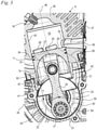
- the structure of the two-stroke engine 9 is in 3 shown in detail.
- the two-stroke engine 9 has a cylinder 38 in which a combustion chamber 25 is formed.
- the combustion chamber 25 is delimited by the piston 19 and the cylinder 38 .
- the spark plug 18 projects into the combustion chamber 25 .
- the cylinder 38 has a cylinder bore which forms a piston track 43 for the piston 19 .
- the piston 19 is guided back and forth along the piston track 43 .
- the two-stroke engine 9 has a crankcase 39 in which a crankcase interior 40 is formed, which is delimited by the piston 19 .
- the crankcase interior 40 and the combustion chamber 25 are separated from the piston 19 .
- Crankcase interior 40 and combustion chamber 25 are in the area of the in 3 illustrated bottom dead center of the piston 19 via one or more overflow channels 26 fluidly connected to each other.
- the overflow channels 26 have a branch 27 near the inlet, which opens into the combustion chamber 25 with an overflow window 29 near the inlet.
- the overflow channels also have a branch 28 near the outlet, which opens into the combustion chamber 25 via an overflow window 30 near the outlet.
- the overflow windows 29 and 30 are controlled by the piston 19.
- two overflow channels 26 are provided, which are on opposite sides of the center plane 44 of the two-stroke engine 9 ( 2 ) run and each open into the combustion chamber 25 via an overflow window 29 and an overflow window 30 .
- the overflow channel 26 opens into the crankcase interior 40 at an outlet opening 31 .
- a single outlet opening 31 is provided, at which both overflow channels 26 open into the crankcase interior 40 .
- the intake channel 11 opens into the crankcase interior 40 with a mixture inlet opening 33 .
- the mixture inlet opening 33 is open towards the interior 40 of the crankcase.
- An outlet opening 35 leads out of the combustion chamber 25 .
- the outlet opening 35 is connected to an exhaust gas silencer 37 via an outlet channel 36 formed in the cylinder 38 .
- the inside 3 not shown air duct 10 ( 1 ) opens out with air inlet openings 34 on the piston track 43.
- an air inlet opening 34 is shown schematically. Two air inlet openings 34 are preferably provided on opposite sides of the center plane 44 of the two-stroke engine 9 .
- the air inlet opening 34 in the area of the top dead center of the piston 19 is connected to the transfer ports 29 and 30 via a schematically illustrated piston pocket 62 of the piston 19, so that air can be stored upstream in the transfer ports 26 via the air duct 10 and the piston pocket 62.
- the mixture inlet opening 33 is opened during the upward stroke of the piston 19, and the fuel/air mixture from the intake channel 11 is sucked into the interior space 40 of the crankcase.
- the air channel 10 ( 1 ) is connected to the overflow windows 29 and 30 via the piston pocket 62, and largely fuel-free air from the air duct 11 is pre-stored in the overflow ducts 26.
- the fuel/air mixture in the crankcase interior 40 is compressed.
- the transfer windows 29 and 30 are opened by the piston 19 moving downwards, the fuel-free air stored upstream in the transfer channels 26 first flows into the combustion chamber 25 .
- the fuel-free air flushes exhaust gases that are still present out of the combustion chamber 25 through the opened outlet 35 .
- Fresh mixture then flows from the crankcase interior 40 into the combustion chamber 25 .
- the fresh mixture in the combustion chamber 25 is compressed and ignited by the spark plug 18 in the region of the top dead center of the piston 19.
- the outlet opening 35 is first opened, so that exhaust gases can flow out of the combustion chamber 25. Any remaining exhaust gases are flushed out of the combustion chamber 25 via the air stored upstream in the overflow channels 26 before fresh mixture flows from the crankcase interior 40 into the combustion chamber 25 for the next engine cycle.
- crankcase 39 has a crankcase plane 45 which contains the axis of rotation 22 of the crankshaft 21 and which is perpendicular to the longitudinal axis 46 of the cylinder. 3 shows the piston 19 at bottom dead center.
- the crankcase plane 45 runs perpendicular to the 2 shown center plane 44 of the two-stroke engine 9.
- the crankcase 39 On the side facing the cylinder 38, the crankcase 39 has a recess 41 into which a collar 42 of the cylinder 38 protrudes.
- the collar 42 delimits the overflow channels 26 in the section formed in the crankcase 39 .
- the overflow channels 26 in the crankcase 39 can be produced as a depression that is open toward the crankcase interior 40 .
- the piston 19 has a distance k to the crankcase plane 45 at bottom dead center.
- the crankshaft 22 has crank webs 32 which dip into the piston 19 in the region of the bottom dead center of the piston 19 .
- the crankcase 39 has a recess 53, which will be described in more detail below.
- the recess 53 is formed in a side wall 51 of the crankcase 39 .
- the recess 53 has a maximum distance r from the axis of rotation 22 of the crankshaft 21. How 3 shows, the distance k of the piston 19 to the crankcase plane 45 at the bottom dead center of the piston 19 is smaller than the maximum distance r.
- the crankshaft 21 is mounted in the side wall 51 with a crankshaft bearing 47 .
- the recess 53 extends over an angle a about the axis of rotation 22 of the crankshaft 21, which is at least 45 ° and at most is 320°.
- the angle a is preferably at least 90°, in particular at least 180°.
- the angle ⁇ is preferably less than 300°. In the exemplary embodiment, an angle ⁇ is provided which is approximately 270° to 290°.
- the recess 53 extends radially outside an outer circumference 61 of the crankshaft bearing 47.
- the recess 53 has a first, inlet-side end 55 and a second, outlet-side end 56. At the first end 55 is an end wall 65 and at the second end an end wall 66 on the recess 53 provided.
- the two end walls 65 and 66 close the recess 53 in the circumferential direction of the axis of rotation 21.
- the two end walls 65 and 66 are connected to one another via a stiffening rib 49 in the exemplary embodiment.
- the depression 53 and the stiffening rib 49 together completely enclose the crankshaft bearing 47 arranged in the side wall 51 .
- the depression 53 has an interruption 64 which divides the depression 53 into a first depression 53a and a second depression 53b.
- the end wall 65 is located at a first end 55 of the recess 53a and the end wall 66 is located at a second end 56 of the recess 53b.
- the discontinuity 64 forms an end wall delimiting the recess 53a at its second end and the recess 53b at its first end.
- Each of the depressions 53a and 53b extends over an angle ⁇ (not shown) of at least 45° and at most 320° around the axis of rotation 22 of the crankshaft 21.
- the outer circumference 61 of the crankshaft bearing 47 has a distance a to a circumferential wall 60 of the crankcase 39 .
- the recess 53 has a maximum depth c measured radially to the axis of rotation 22 of the crankshaft 21 .
- the depth c is advantageously at least 30%, in particular at least 40%, preferably at least 50% of the distance a between the outer circumference 61 of the crankshaft bearing 47 and the circumferential wall 60 of the crankcase interior 40.
- the end wall 65 has a thickness m measured parallel to the longitudinal axis 46 of the cylinder and the end wall 66 has a thickness n measured parallel to the longitudinal axis 46 of the cylinder.
- the thicknesses m and n are the smallest thicknesses of the end walls 65, 66 measured parallel to the longitudinal axis 46 of the cylinder.
- the thicknesses n and m are advantageously less than the depth c of the depression 53.
- the piston 19 is at a distance o from the end wall 65. As a result, the piston 19 cannot come into contact with the end wall 65. There is a corresponding distance p to the end wall 66.
- the two-stroke engine 9 has an in 4 drawn section plane 59, which runs perpendicular to the longitudinal axis 46 of the cylinder.
- the cutting plane 59 extends in such a way that it intersects both the recess 53 and the orifice 31 . Accordingly, the depression 53 extends in relation to the cylinder longitudinal axis 46 up to the height of the orifice opening 31.
- the height in relation to the cylinder longitudinal axis 46 denotes the altitude in relation to an arrangement in which the cylinder longitudinal axis 46 is arranged vertically and the crankcase 39 is below the Combustion chamber 25 is located. how 4 shows, the cutting plane 59 also intersects the crankshaft bearing 47.
- the stroke h of the two-stroke engine 9 is also shown.
- the stroke h of the two-stroke engine 9 is the distance measured in the direction of the cylinder longitudinal axis 46, which the piston 19 travels between the in 4 illustrated position at bottom dead center and the position of the piston 19 travels at top dead center.
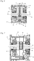
- figure 5 shows a view of the side wall 51 opposite side wall 52. How figure 5 shows, the crankshaft 21 is supported in the side wall 52 with a crankshaft bearing 48 .
- the side wall 52 has a depression 54 .
- the depression 54 is delimited at its inlet-side end 57 by a terminating wall 67 and at its outlet-side end 58 by a terminating wall 68.
- the two terminating walls 67 and 68 are connected to one another via a stiffening rib 50 in the exemplary embodiment.
- the recess 54 runs along the outer circumference 61 of the second crankshaft bearing 48 and at a distance s from the outer circumference 61 of the crankshaft bearing 48.
- the distance s is advantageously less than 60%, in particular less than 30%, preferably less than 20% of the distance t.
- the recess 54 has a distance u from the axis of rotation 21 of the crankshaft 22, which is smaller than the distance t.
- the distance u is advantageously less than 90%, in particular less than 80%, preferably less than 75% of the distance t.
- the depression 43 advantageously has corresponding distances s and u.
- the depression 54 has a depth d, measured radially to the axis of rotation 22, which preferably corresponds to the depth c of the depression 43 ( 4 ) is equivalent to.
- the end walls 65 and 67 and the end walls 66 and 68 are preferably approximately mirror-symmetrical to the center plane 44 ( 2 ) arranged.
- the stiffening ribs 49 and 50 are also preferably arranged at least partially symmetrically to the center plane 44 .
- elevations 63 are arranged in the depressions 52 and 54, at which the depressions 53 and 54 have a smaller depth than the maximum depth c or d.
- the elevations 63 are advantageously formed by screw bosses on the outside of the crankcase 39 .
- the stiffening ribs 49 and 50 run at a distance from the piston 19 at the bottom dead center of the piston 19, so that the piston 19 cannot come into contact with the stiffening ribs 49 and 50.
- the orifice opening 31 is partially delimited in the direction of the axis of rotation 22 by the end walls 66 and 68 .
- the cylinder 38 and the orifice 31 of the at least one overflow channel 26 are arranged on the same side of the crankcase plane 45 in the exemplary embodiment.
- the crankcase plane 45 does not intersect the overflow channel 26 .
- another arrangement can also be advantageous.
- the end walls 66 and 68 protrude up to the collar 42.
- the arrangement of the end walls 65 to 68 and the Stiffening ribs 49 and 50 close to the cylinder 38 cause the crankcase 39 to be stiffened in the area where the cylinder 38 is usually bolted to the crankcase 39 .
- the end walls 65 to 68 and the stiffening ribs 49 and 50 increase the stability of the two-stroke engine 9 without increasing the installation space of the two-stroke engine 1 .
- the side walls 51 and 52 preferably run on the outer circumference 61 of the crankshaft bearings 47, 48 in sectional planes running perpendicularly to the axis of rotation 22, which intersect the crankshaft bearings 47 and 48 in a middle region between the end faces of the crankshaft bearings 47 and 48. This achieves good support for the crankshaft bearings 47 and 48 and a favorable power flow.
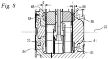
- the depression 53 has a width b measured axially, ie in the direction of the axis of rotation 22 .
- the recess 54 has a width e.
- the width e and the width b are advantageously of different sizes.
- the width e is in particular greater than the width b.
- the depressions 53 and 54 are therefore advantageously designed asymmetrically to the center plane 44, although the extension of the depressions 53 and 54 around the crankshaft bearings 47 and 48 is preferably approximately symmetrical to the center plane 44.
- the width b and the width e are significantly smaller than the width f of the crankshaft bearing 47 and 48 measured parallel to the axis of rotation 22.
- the width b, e of the depressions 53 and 54 is preferably at least 10% of the width f of the crankshaft bearing 47 or 48.
- the width b, e of the depressions 53 and 54 is preferably less than 60%, in particular less than 40% of the width f of the crankshaft bearings 47 and 48.
- the width b and e of the depressions 53 and 54 is preferably at least 5% of the stroke h ( 4 ) of the two-stroke engine 9. In a further preferred embodiment it can be provided that the width e and the width b are equal. In Another preferred embodiment can provide that the width e is smaller than the width b.
- the end wall 65 has a width i measured parallel to the axis of rotation 22 .
- the end wall 68 has a width g measured parallel to the axis of rotation 22 .
- the width g is greater than the width i.
- the width i is greater than the width g. In a further alternative embodiment, it can also be provided that the width i and the width b are of the same size.
- the depression is open to the crankcase interior over an angle ⁇ of at least 45° and at most 320° around the axis of rotation of the crankshaft, and the depression extends over an angle that is greater than the angle ⁇ around the axis of rotation of the crankshaft .
- the depression 53, 54 is not open over its entire length towards the interior of the crankcase, but rather over a partial section of its length.
- at least one end of the recess can be designed in the manner of a blind hole. Provision can also be made for a section of the recess to be designed to be closed towards the crankcase interior in a region which is at a distance from the ends of the recess.
- the portion of the length over which the recess is open to the crankcase interior is advantageously at least 80% of the length of the recess.
Landscapes
- Engineering & Computer Science (AREA)
- Chemical & Material Sciences (AREA)
- Combustion & Propulsion (AREA)
- Mechanical Engineering (AREA)
- General Engineering & Computer Science (AREA)
- Cylinder Crankcases Of Internal Combustion Engines (AREA)
Claims (13)
- Moteur à deux temps comportant un cylindre (38) et un carter de vilebrequin (39), une chambre de combustion (25) étant formée dans le cylindre (38), laquelle est délimitée par un piston (19) monté dans le cylindre (38) de manière à pouvoir effectuer un mouvement de va-et-vient, le piston (19) entraînant en rotation un vilebrequin (21) monté à rotation dans le carter de vilebrequin (39), le carter de vilebrequin (39) comprenant un espace intérieur de carter de vilebrequin (40), l'espace intérieur de carter de vilebrequin (40) et la chambre de combustion (25) étant reliés l'un à l'autre de manière fluidique par le biais d'au moins un canal de transfert (26) dans au moins une position du piston (19), comportant un canal d'aspiration (11) débouchant dans l'espace intérieur de carter de vilebrequin (40) et comportant un dispositif d'amenée de carburant (13), l'espace intérieur de carter de vilebrequin (40) étant délimité par deux parois latérales (51, 52) en regard l'une de l'autre en direction de l'axe de rotation (22) du vilebrequin (21), le vilebrequin (21) étant monté à l'aide d'au moins un palier de vilebrequin (47, 48) disposé dans une paroi latérale (51, 52),
un évidement (53, 53a, 53b, 54) s'étendant autour du palier de vilebrequin (47, 48) dans au moins une paroi latérale (51, 52), l'évidement (53, 53a, 53b, 54) s'étendant autour de l'axe de rotation (22) du vilebrequin (21),
caractérisé en ce que l'évidement (53, 53a, 53b, 54) est ouvert vers l'espace intérieur de carter de vilebrequin (40) sur un angle (a) d'au moins 45° et d'au maximum 320° autour de l'axe de rotation (22) du vilebrequin (21) et en ce qu'une paroi de fermeture (65, 66, 67, 68) est disposée à chaque extrémité (55, 56, 57, 58) de l'évidement (53, 53a, 53b, 54). - Moteur à deux temps selon la revendication 1,
caractérisé en ce que l'évidement (53, 53a, 53b, 54) s'étend sur un angle (a) d'au moins 45° et d'au maximum 320° autour de l'axe de rotation (22) du vilebrequin (21). - Moteur à deux temps selon la revendication 1 ou 2,
caractérisé en ce que l'évidement (53, 53a, 53b, 54) est ouvert vers l'espace intérieur de carter de vilebrequin (40) sur au moins 80% de sa longueur. - Moteur à deux temps selon l'une des revendications 1 à 3,
caractérisé en ce que deux parois de fermeture (65, 66, 67, 68) sont reliées l'une à l'autre par le biais d'une nervure de raidissement (49, 50). - Moteur à deux temps selon l'une des revendications 1 à 4,
caractérisé en ce que la distance (k) du piston (19) au point mort bas du piston (19) à un plan de carter de vilebrequin (45), qui contient l'axe de rotation (22) du vilebrequin (21) et qui s'étend perpendiculairement à un axe longitudinal de cylindre (46), est inférieure à la plus grande distance (r) de l'évidement (53, 54) à l'axe de rotation (22) du vilebrequin (21). - Moteur à deux temps selon l'une des revendications 1 à 5,
caractérisé en ce que l'au moins un canal de transfert (26) débouche par une ouverture de débouché (31) dans l'espace intérieur de carter de vilebrequin (40) et en ce qu'au moins un plan de coupe (59) existe, lequel s'étend perpendiculairement à l'axe longitudinal de cylindre (46) et coupe à la fois l'évidement (53, 53b, 54) et l'ouverture de débouché (31). - Moteur à deux temps selon l'une des revendications 1 à 6,
caractérisé en ce que la profondeur (c, d) de l'évidement (53, 53a, 53b, 54), mesurée dans la direction radiale par rapport à l'axe de rotation (22) du vilebrequin (21), vaut, au moins sur une partie de la longueur de l'évidement (53, 53a, 53b, 54), au moins 30% de la distance radiale (a) entre la périphérie extérieure (61) du palier de vilebrequin (47, 48) et la paroi périphérique (60) de l'espace intérieur de carter de vilebrequin (40). - Moteur à deux temps selon l'une des revendications 1 à 7,
caractérisé en ce que la largeur (b, e) de l'évidement (53, 53a, 53b, 54), mesurée parallèlement à l'axe de rotation (22) du vilebrequin (21), vaut au moins 10% de la largeur (f) du palier de vilebrequin (47, 48). - Moteur à deux temps selon l'une des revendications 1 à 8,
caractérisé en ce que la largeur (b, e) de l'évidement (53, 53a, 53b, 54), mesurée parallèlement à l'axe de rotation (22) du vilebrequin (21), vaut au moins 5% de la course (h) du moteur à deux temps (9). - Moteur à deux temps selon l'une des revendications 1 à 9,
caractérisé en ce que les deux parois latérales (51, 52) de l'espace intérieur de carter de vilebrequin (40) comprennent au moins un évidement (53, 53a, 53b, 54) s'étendant autour du palier de vilebrequin (47, 48). - Moteur à deux temps selon l'une des revendications 1 à 10,
caractérisé en ce que l'au moins un canal de transfert (26) débouche par une ouverture de débouché (31) dans l'espace intérieur de carter de vilebrequin (40), et en ce que l'ouverture de débouché (31) est délimitée au moins partiellement par une paroi de fermeture (66, 68) en direction de l'axe de rotation (22) du vilebrequin (21). - Moteur à deux temps selon l'une des revendications 1 à 11,
caractérisé en ce que le moteur à deux temps (9) comprend un plan de carter de vilebrequin (45) qui contient l'axe de rotation (22) du vilebrequin (21) et qui s'étend perpendiculairement à l'axe longitudinal de cylindre (46) et en ce que le cylindre (38) et l'ouverture de débouché (31) de l'au moins un canal de transfert (26) sont disposés sur le même côté du plan de carter de vilebrequin (45). - Moteur à deux temps selon l'une des revendications 1 à 12,
caractérisé en ce que le moteur à deux temps (9) comprend un canal d'air (10) pour l'amenée d'air de balayage stratifié jusqu'à au moins un canal de transfert (26).
Priority Applications (1)
| Application Number | Priority Date | Filing Date | Title |
|---|---|---|---|
| EP19164939.1A EP3715599B1 (fr) | 2019-03-25 | 2019-03-25 | Moteur à deux temps |
Applications Claiming Priority (1)
| Application Number | Priority Date | Filing Date | Title |
|---|---|---|---|
| EP19164939.1A EP3715599B1 (fr) | 2019-03-25 | 2019-03-25 | Moteur à deux temps |
Publications (2)
| Publication Number | Publication Date |
|---|---|
| EP3715599A1 EP3715599A1 (fr) | 2020-09-30 |
| EP3715599B1 true EP3715599B1 (fr) | 2022-02-23 |
Family
ID=65955106
Family Applications (1)
| Application Number | Title | Priority Date | Filing Date |
|---|---|---|---|
| EP19164939.1A Active EP3715599B1 (fr) | 2019-03-25 | 2019-03-25 | Moteur à deux temps |
Country Status (1)
| Country | Link |
|---|---|
| EP (1) | EP3715599B1 (fr) |
Families Citing this family (1)
| Publication number | Priority date | Publication date | Assignee | Title |
|---|---|---|---|---|
| IT202400000063A1 (it) * | 2024-01-04 | 2025-07-04 | Emak Spa | Motore a combustione interna a due tempi con sistema di travaso perfezionato |
Family Cites Families (7)
| Publication number | Priority date | Publication date | Assignee | Title |
|---|---|---|---|---|
| CN102792000B (zh) * | 2010-04-27 | 2014-11-26 | 三菱重工业株式会社 | 二冲程发动机的扫气通路构造 |
| WO2012090256A1 (fr) | 2010-12-28 | 2012-07-05 | Husqvarna Zenoah Co., Ltd. | Moteur à deux temps |
| US8967101B2 (en) * | 2011-09-09 | 2015-03-03 | Andreas Stihl Ag & Co. Kg | Two-stroke engine and a method for the operation thereof |
| DE102011120464A1 (de) | 2011-12-07 | 2013-06-13 | Andreas Stihl Ag & Co. Kg | Arbeitsgerät |
| CN103790690B (zh) | 2014-02-21 | 2017-03-08 | 浙江天泰机械有限公司 | 一种汽油机 |
| JP6255318B2 (ja) * | 2014-08-01 | 2017-12-27 | 本田技研工業株式会社 | ユニフロー2ストロークエンジン |
| DE102015013786A1 (de) * | 2015-10-20 | 2017-04-20 | Andreas Stihl Ag & Co. Kg | Zweitaktmotor |
-
2019
- 2019-03-25 EP EP19164939.1A patent/EP3715599B1/fr active Active
Also Published As
| Publication number | Publication date |
|---|---|
| EP3715599A1 (fr) | 2020-09-30 |
Similar Documents
| Publication | Publication Date | Title |
|---|---|---|
| DE19512566C2 (de) | Zweitaktmotor mit mehreren Überströmkanälen | |
| DE102009030593B4 (de) | Vergaser und Zweitaktmotor mit einem Vergaser | |
| EP3284938B1 (fr) | Piston pour un moteur a deux temps dote d'un pot catalytique et moteur deux temps | |
| EP1141529A1 (fr) | Moteur deux temps a stratification de la charge | |
| EP3284939B1 (fr) | Piston pour un moteur a deux temps dote d'un pot catalytique et moteur deux temps | |
| EP3748151B1 (fr) | Unité de formation de mélange et moteur à deux temps doté d'une unité de formation de mélange | |
| DE102020000989A1 (de) | Zweitaktmotor und Verfahren zum Betrieb eines Zweitaktmotors | |
| DE102007054929B4 (de) | Handgeführtes Arbeitsgerät | |
| DE10321571A1 (de) | Zweitaktmotor mit Spülvorlage | |
| DE10064719B4 (de) | Zweitaktmotor mit Ladungsschichtung | |
| EP3715599B1 (fr) | Moteur à deux temps | |
| DE10019983B4 (de) | Druckgusszylinder für einen Zweitaktmotor | |
| DE102009059145A1 (de) | Verbrennungsmotor | |
| DE102010045017B4 (de) | Zweitaktmotor | |
| DE102015013785B4 (de) | Zweitaktmotor und Baureihe von Zweitaktmotoren | |
| WO2003100229A1 (fr) | Moteur a deux temps | |
| DE102022126966B4 (de) | Handgeführtes Arbeitsgerät und Pralltopf für dessen Verbrennungsmotor | |
| DE102006001570B4 (de) | Arbeitsgerät | |
| DE102023117841A1 (de) | Abgasschalldämpfer und Auslassstutzen für einen Abgasschalldämpfer | |
| DE102012004322A1 (de) | Zweitaktmotor mit einer Ansaugvorrichtung | |
| DE102010045016B4 (de) | Handgeführtes Arbeitsgerät | |
| DE19618266A1 (de) | Zweitaktmotor mit Spülkanälen | |
| DE102015013784B4 (de) | Handgeführtes Arbeitsgerät mit einem luftgekühlten Verbrennungsmotor | |
| DE102007052420A1 (de) | Verbrennungsmotor | |
| DE10319216A1 (de) | Zweitaktmotor |
Legal Events
| Date | Code | Title | Description |
|---|---|---|---|
| PUAI | Public reference made under article 153(3) epc to a published international application that has entered the european phase |
Free format text: ORIGINAL CODE: 0009012 |
|
| STAA | Information on the status of an ep patent application or granted ep patent |
Free format text: STATUS: THE APPLICATION HAS BEEN PUBLISHED |
|
| AK | Designated contracting states |
Kind code of ref document: A1 Designated state(s): AL AT BE BG CH CY CZ DE DK EE ES FI FR GB GR HR HU IE IS IT LI LT LU LV MC MK MT NL NO PL PT RO RS SE SI SK SM TR |
|
| AX | Request for extension of the european patent |
Extension state: BA ME |
|
| STAA | Information on the status of an ep patent application or granted ep patent |
Free format text: STATUS: REQUEST FOR EXAMINATION WAS MADE |
|
| 17P | Request for examination filed |
Effective date: 20210316 |
|
| RBV | Designated contracting states (corrected) |
Designated state(s): AL AT BE BG CH CY CZ DE DK EE ES FI FR GB GR HR HU IE IS IT LI LT LU LV MC MK MT NL NO PL PT RO RS SE SI SK SM TR |
|
| RIC1 | Information provided on ipc code assigned before grant |
Ipc: F02B 75/02 20060101ALN20210802BHEP Ipc: F02F 7/00 20060101ALI20210802BHEP Ipc: F02M 35/10 20060101ALI20210802BHEP Ipc: F02B 63/02 20060101AFI20210802BHEP |
|
| GRAP | Despatch of communication of intention to grant a patent |
Free format text: ORIGINAL CODE: EPIDOSNIGR1 |
|
| STAA | Information on the status of an ep patent application or granted ep patent |
Free format text: STATUS: GRANT OF PATENT IS INTENDED |
|
| INTG | Intention to grant announced |
Effective date: 20210917 |
|
| GRAS | Grant fee paid |
Free format text: ORIGINAL CODE: EPIDOSNIGR3 |
|
| GRAA | (expected) grant |
Free format text: ORIGINAL CODE: 0009210 |
|
| STAA | Information on the status of an ep patent application or granted ep patent |
Free format text: STATUS: THE PATENT HAS BEEN GRANTED |
|
| AK | Designated contracting states |
Kind code of ref document: B1 Designated state(s): AL AT BE BG CH CY CZ DE DK EE ES FI FR GB GR HR HU IE IS IT LI LT LU LV MC MK MT NL NO PL PT RO RS SE SI SK SM TR |
|
| REG | Reference to a national code |
Ref country code: GB Ref legal event code: FG4D Free format text: NOT ENGLISH |
|
| REG | Reference to a national code |
Ref country code: CH Ref legal event code: EP |
|
| REG | Reference to a national code |
Ref country code: AT Ref legal event code: REF Ref document number: 1470632 Country of ref document: AT Kind code of ref document: T Effective date: 20220315 |
|
| REG | Reference to a national code |
Ref country code: IE Ref legal event code: FG4D Free format text: LANGUAGE OF EP DOCUMENT: GERMAN |
|
| REG | Reference to a national code |
Ref country code: DE Ref legal event code: R096 Ref document number: 502019003453 Country of ref document: DE |
|
| REG | Reference to a national code |
Ref country code: LT Ref legal event code: MG9D |
|
| REG | Reference to a national code |
Ref country code: NL Ref legal event code: MP Effective date: 20220223 |
|
| PG25 | Lapsed in a contracting state [announced via postgrant information from national office to epo] |
Ref country code: SE Free format text: LAPSE BECAUSE OF FAILURE TO SUBMIT A TRANSLATION OF THE DESCRIPTION OR TO PAY THE FEE WITHIN THE PRESCRIBED TIME-LIMIT Effective date: 20220223 Ref country code: RS Free format text: LAPSE BECAUSE OF FAILURE TO SUBMIT A TRANSLATION OF THE DESCRIPTION OR TO PAY THE FEE WITHIN THE PRESCRIBED TIME-LIMIT Effective date: 20220223 Ref country code: PT Free format text: LAPSE BECAUSE OF FAILURE TO SUBMIT A TRANSLATION OF THE DESCRIPTION OR TO PAY THE FEE WITHIN THE PRESCRIBED TIME-LIMIT Effective date: 20220623 Ref country code: NO Free format text: LAPSE BECAUSE OF FAILURE TO SUBMIT A TRANSLATION OF THE DESCRIPTION OR TO PAY THE FEE WITHIN THE PRESCRIBED TIME-LIMIT Effective date: 20220523 Ref country code: NL Free format text: LAPSE BECAUSE OF FAILURE TO SUBMIT A TRANSLATION OF THE DESCRIPTION OR TO PAY THE FEE WITHIN THE PRESCRIBED TIME-LIMIT Effective date: 20220223 Ref country code: LT Free format text: LAPSE BECAUSE OF FAILURE TO SUBMIT A TRANSLATION OF THE DESCRIPTION OR TO PAY THE FEE WITHIN THE PRESCRIBED TIME-LIMIT Effective date: 20220223 Ref country code: HR Free format text: LAPSE BECAUSE OF FAILURE TO SUBMIT A TRANSLATION OF THE DESCRIPTION OR TO PAY THE FEE WITHIN THE PRESCRIBED TIME-LIMIT Effective date: 20220223 Ref country code: ES Free format text: LAPSE BECAUSE OF FAILURE TO SUBMIT A TRANSLATION OF THE DESCRIPTION OR TO PAY THE FEE WITHIN THE PRESCRIBED TIME-LIMIT Effective date: 20220223 Ref country code: BG Free format text: LAPSE BECAUSE OF FAILURE TO SUBMIT A TRANSLATION OF THE DESCRIPTION OR TO PAY THE FEE WITHIN THE PRESCRIBED TIME-LIMIT Effective date: 20220523 |
|
| PG25 | Lapsed in a contracting state [announced via postgrant information from national office to epo] |
Ref country code: PL Free format text: LAPSE BECAUSE OF FAILURE TO SUBMIT A TRANSLATION OF THE DESCRIPTION OR TO PAY THE FEE WITHIN THE PRESCRIBED TIME-LIMIT Effective date: 20220223 Ref country code: LV Free format text: LAPSE BECAUSE OF FAILURE TO SUBMIT A TRANSLATION OF THE DESCRIPTION OR TO PAY THE FEE WITHIN THE PRESCRIBED TIME-LIMIT Effective date: 20220223 Ref country code: GR Free format text: LAPSE BECAUSE OF FAILURE TO SUBMIT A TRANSLATION OF THE DESCRIPTION OR TO PAY THE FEE WITHIN THE PRESCRIBED TIME-LIMIT Effective date: 20220524 Ref country code: FI Free format text: LAPSE BECAUSE OF FAILURE TO SUBMIT A TRANSLATION OF THE DESCRIPTION OR TO PAY THE FEE WITHIN THE PRESCRIBED TIME-LIMIT Effective date: 20220223 |
|
| PG25 | Lapsed in a contracting state [announced via postgrant information from national office to epo] |
Ref country code: IS Free format text: LAPSE BECAUSE OF FAILURE TO SUBMIT A TRANSLATION OF THE DESCRIPTION OR TO PAY THE FEE WITHIN THE PRESCRIBED TIME-LIMIT Effective date: 20220623 |
|
| PG25 | Lapsed in a contracting state [announced via postgrant information from national office to epo] |
Ref country code: SM Free format text: LAPSE BECAUSE OF FAILURE TO SUBMIT A TRANSLATION OF THE DESCRIPTION OR TO PAY THE FEE WITHIN THE PRESCRIBED TIME-LIMIT Effective date: 20220223 Ref country code: SK Free format text: LAPSE BECAUSE OF FAILURE TO SUBMIT A TRANSLATION OF THE DESCRIPTION OR TO PAY THE FEE WITHIN THE PRESCRIBED TIME-LIMIT Effective date: 20220223 Ref country code: RO Free format text: LAPSE BECAUSE OF FAILURE TO SUBMIT A TRANSLATION OF THE DESCRIPTION OR TO PAY THE FEE WITHIN THE PRESCRIBED TIME-LIMIT Effective date: 20220223 Ref country code: EE Free format text: LAPSE BECAUSE OF FAILURE TO SUBMIT A TRANSLATION OF THE DESCRIPTION OR TO PAY THE FEE WITHIN THE PRESCRIBED TIME-LIMIT Effective date: 20220223 Ref country code: DK Free format text: LAPSE BECAUSE OF FAILURE TO SUBMIT A TRANSLATION OF THE DESCRIPTION OR TO PAY THE FEE WITHIN THE PRESCRIBED TIME-LIMIT Effective date: 20220223 Ref country code: CZ Free format text: LAPSE BECAUSE OF FAILURE TO SUBMIT A TRANSLATION OF THE DESCRIPTION OR TO PAY THE FEE WITHIN THE PRESCRIBED TIME-LIMIT Effective date: 20220223 |
|
| REG | Reference to a national code |
Ref country code: CH Ref legal event code: PL |
|
| REG | Reference to a national code |
Ref country code: DE Ref legal event code: R097 Ref document number: 502019003453 Country of ref document: DE |
|
| PG25 | Lapsed in a contracting state [announced via postgrant information from national office to epo] |
Ref country code: MC Free format text: LAPSE BECAUSE OF FAILURE TO SUBMIT A TRANSLATION OF THE DESCRIPTION OR TO PAY THE FEE WITHIN THE PRESCRIBED TIME-LIMIT Effective date: 20220223 Ref country code: AL Free format text: LAPSE BECAUSE OF FAILURE TO SUBMIT A TRANSLATION OF THE DESCRIPTION OR TO PAY THE FEE WITHIN THE PRESCRIBED TIME-LIMIT Effective date: 20220223 |
|
| REG | Reference to a national code |
Ref country code: BE Ref legal event code: MM Effective date: 20220331 |
|
| PLBE | No opposition filed within time limit |
Free format text: ORIGINAL CODE: 0009261 |
|
| STAA | Information on the status of an ep patent application or granted ep patent |
Free format text: STATUS: NO OPPOSITION FILED WITHIN TIME LIMIT |
|
| PG25 | Lapsed in a contracting state [announced via postgrant information from national office to epo] |
Ref country code: LU Free format text: LAPSE BECAUSE OF NON-PAYMENT OF DUE FEES Effective date: 20220325 Ref country code: LI Free format text: LAPSE BECAUSE OF NON-PAYMENT OF DUE FEES Effective date: 20220331 Ref country code: IE Free format text: LAPSE BECAUSE OF NON-PAYMENT OF DUE FEES Effective date: 20220325 Ref country code: FR Free format text: LAPSE BECAUSE OF NON-PAYMENT OF DUE FEES Effective date: 20220423 Ref country code: CH Free format text: LAPSE BECAUSE OF NON-PAYMENT OF DUE FEES Effective date: 20220331 |
|
| 26N | No opposition filed |
Effective date: 20221124 |
|
| PG25 | Lapsed in a contracting state [announced via postgrant information from national office to epo] |
Ref country code: SI Free format text: LAPSE BECAUSE OF FAILURE TO SUBMIT A TRANSLATION OF THE DESCRIPTION OR TO PAY THE FEE WITHIN THE PRESCRIBED TIME-LIMIT Effective date: 20220223 Ref country code: BE Free format text: LAPSE BECAUSE OF NON-PAYMENT OF DUE FEES Effective date: 20220331 |
|
| PG25 | Lapsed in a contracting state [announced via postgrant information from national office to epo] |
Ref country code: IT Free format text: LAPSE BECAUSE OF FAILURE TO SUBMIT A TRANSLATION OF THE DESCRIPTION OR TO PAY THE FEE WITHIN THE PRESCRIBED TIME-LIMIT Effective date: 20220223 |
|
| GBPC | Gb: european patent ceased through non-payment of renewal fee |
Effective date: 20230325 |
|
| PG25 | Lapsed in a contracting state [announced via postgrant information from national office to epo] |
Ref country code: GB Free format text: LAPSE BECAUSE OF NON-PAYMENT OF DUE FEES Effective date: 20230325 |
|
| PG25 | Lapsed in a contracting state [announced via postgrant information from national office to epo] |
Ref country code: GB Free format text: LAPSE BECAUSE OF NON-PAYMENT OF DUE FEES Effective date: 20230325 |
|
| PG25 | Lapsed in a contracting state [announced via postgrant information from national office to epo] |
Ref country code: MK Free format text: LAPSE BECAUSE OF FAILURE TO SUBMIT A TRANSLATION OF THE DESCRIPTION OR TO PAY THE FEE WITHIN THE PRESCRIBED TIME-LIMIT Effective date: 20220223 Ref country code: CY Free format text: LAPSE BECAUSE OF FAILURE TO SUBMIT A TRANSLATION OF THE DESCRIPTION OR TO PAY THE FEE WITHIN THE PRESCRIBED TIME-LIMIT Effective date: 20220223 |
|
| PG25 | Lapsed in a contracting state [announced via postgrant information from national office to epo] |
Ref country code: HU Free format text: LAPSE BECAUSE OF FAILURE TO SUBMIT A TRANSLATION OF THE DESCRIPTION OR TO PAY THE FEE WITHIN THE PRESCRIBED TIME-LIMIT; INVALID AB INITIO Effective date: 20190325 |
|
| PG25 | Lapsed in a contracting state [announced via postgrant information from national office to epo] |
Ref country code: TR Free format text: LAPSE BECAUSE OF FAILURE TO SUBMIT A TRANSLATION OF THE DESCRIPTION OR TO PAY THE FEE WITHIN THE PRESCRIBED TIME-LIMIT Effective date: 20220223 |
|
| PG25 | Lapsed in a contracting state [announced via postgrant information from national office to epo] |
Ref country code: MT Free format text: LAPSE BECAUSE OF FAILURE TO SUBMIT A TRANSLATION OF THE DESCRIPTION OR TO PAY THE FEE WITHIN THE PRESCRIBED TIME-LIMIT Effective date: 20220223 |
|
| REG | Reference to a national code |
Ref country code: AT Ref legal event code: MM01 Ref document number: 1470632 Country of ref document: AT Kind code of ref document: T Effective date: 20240325 |
|
| PG25 | Lapsed in a contracting state [announced via postgrant information from national office to epo] |
Ref country code: AT Free format text: LAPSE BECAUSE OF NON-PAYMENT OF DUE FEES Effective date: 20240325 |
|
| PGFP | Annual fee paid to national office [announced via postgrant information from national office to epo] |
Ref country code: DE Payment date: 20260320 Year of fee payment: 8 |
|
| PGFP | Annual fee paid to national office [announced via postgrant information from national office to epo] |
Ref country code: AT Payment date: 20260410 Year of fee payment: 5 |