EP3716205B1 - Vorrichtung zum erfassen von hotspots - Google Patents
Vorrichtung zum erfassen von hotspots Download PDFInfo
- Publication number
- EP3716205B1 EP3716205B1 EP19165287.4A EP19165287A EP3716205B1 EP 3716205 B1 EP3716205 B1 EP 3716205B1 EP 19165287 A EP19165287 A EP 19165287A EP 3716205 B1 EP3716205 B1 EP 3716205B1
- Authority
- EP
- European Patent Office
- Prior art keywords
- hot spot
- image
- pixels
- temperature
- pixel
- Prior art date
- Legal status (The legal status is an assumption and is not a legal conclusion. Google has not performed a legal analysis and makes no representation as to the accuracy of the status listed.)
- Active
Links
Images


Classifications
-
- G—PHYSICS
- G01—MEASURING; TESTING
- G01J—MEASUREMENT OF INTENSITY, VELOCITY, SPECTRAL CONTENT, POLARISATION, PHASE OR PULSE CHARACTERISTICS OF INFRARED, VISIBLE OR ULTRAVIOLET LIGHT; COLORIMETRY; RADIATION PYROMETRY
- G01J5/00—Radiation pyrometry, e.g. infrared or optical thermometry
- G01J5/0066—Radiation pyrometry, e.g. infrared or optical thermometry for hot spots detection
-
- G—PHYSICS
- G06—COMPUTING OR CALCULATING; COUNTING
- G06T—IMAGE DATA PROCESSING OR GENERATION, IN GENERAL
- G06T7/00—Image analysis
- G06T7/0002—Inspection of images, e.g. flaw detection
- G06T7/0004—Industrial image inspection
-
- G—PHYSICS
- G06—COMPUTING OR CALCULATING; COUNTING
- G06T—IMAGE DATA PROCESSING OR GENERATION, IN GENERAL
- G06T7/00—Image analysis
- G06T7/10—Segmentation; Edge detection
- G06T7/11—Region-based segmentation
-
- G—PHYSICS
- G06—COMPUTING OR CALCULATING; COUNTING
- G06T—IMAGE DATA PROCESSING OR GENERATION, IN GENERAL
- G06T7/00—Image analysis
- G06T7/10—Segmentation; Edge detection
- G06T7/136—Segmentation; Edge detection involving thresholding
-
- G—PHYSICS
- G06—COMPUTING OR CALCULATING; COUNTING
- G06T—IMAGE DATA PROCESSING OR GENERATION, IN GENERAL
- G06T7/00—Image analysis
- G06T7/10—Segmentation; Edge detection
- G06T7/194—Segmentation; Edge detection involving foreground-background segmentation
-
- G—PHYSICS
- G06—COMPUTING OR CALCULATING; COUNTING
- G06T—IMAGE DATA PROCESSING OR GENERATION, IN GENERAL
- G06T7/00—Image analysis
- G06T7/60—Analysis of geometric attributes
- G06T7/62—Analysis of geometric attributes of area, perimeter, diameter or volume
-
- H—ELECTRICITY
- H04—ELECTRIC COMMUNICATION TECHNIQUE
- H04N—PICTORIAL COMMUNICATION, e.g. TELEVISION
- H04N23/00—Cameras or camera modules comprising electronic image sensors; Control thereof
- H04N23/20—Cameras or camera modules comprising electronic image sensors; Control thereof for generating image signals from infrared radiation only
- H04N23/23—Cameras or camera modules comprising electronic image sensors; Control thereof for generating image signals from infrared radiation only from thermal infrared radiation
-
- G—PHYSICS
- G01—MEASURING; TESTING
- G01J—MEASUREMENT OF INTENSITY, VELOCITY, SPECTRAL CONTENT, POLARISATION, PHASE OR PULSE CHARACTERISTICS OF INFRARED, VISIBLE OR ULTRAVIOLET LIGHT; COLORIMETRY; RADIATION PYROMETRY
- G01J5/00—Radiation pyrometry, e.g. infrared or optical thermometry
- G01J2005/0077—Imaging
-
- G—PHYSICS
- G01—MEASURING; TESTING
- G01J—MEASUREMENT OF INTENSITY, VELOCITY, SPECTRAL CONTENT, POLARISATION, PHASE OR PULSE CHARACTERISTICS OF INFRARED, VISIBLE OR ULTRAVIOLET LIGHT; COLORIMETRY; RADIATION PYROMETRY
- G01J5/00—Radiation pyrometry, e.g. infrared or optical thermometry
- G01J2005/0092—Temperature by averaging, e.g. by scan
-
- G—PHYSICS
- G01—MEASURING; TESTING
- G01J—MEASUREMENT OF INTENSITY, VELOCITY, SPECTRAL CONTENT, POLARISATION, PHASE OR PULSE CHARACTERISTICS OF INFRARED, VISIBLE OR ULTRAVIOLET LIGHT; COLORIMETRY; RADIATION PYROMETRY
- G01J5/00—Radiation pyrometry, e.g. infrared or optical thermometry
- G01J5/80—Calibration
-
- G—PHYSICS
- G06—COMPUTING OR CALCULATING; COUNTING
- G06T—IMAGE DATA PROCESSING OR GENERATION, IN GENERAL
- G06T2207/00—Indexing scheme for image analysis or image enhancement
- G06T2207/10—Image acquisition modality
- G06T2207/10048—Infrared image
Definitions
- the present invention relates to an apparatus for hot spot sensing, a system for hot spot sensing, a low voltage, medium voltage or high voltage switchgear comprising such a system, and to a method for hot spot sensing.
- thermography IRT
- thermal imaging thermal imaging
- thermal video thermal video
- Thermographic cameras usually detect radiation in the long-IR range of the electromagnetic spectrum (roughly 9,000-14,000 nanometers or 9-14 ⁇ m) and produce images of that radiation, called thermograms. Since IR radiation is emitted by all objects with a temperature above absolute zero according to the black body radiation law, thermography makes it possible to see an environment with or without visible illumination. The amount of radiation emitted by an object increases with temperature; therefore, thermography allows to see variations in temperature to be observed and also enables absolute temperatures to be determined from an assumption of an emissivity of a surface of an object.
- US2018/283953A1 describes that flight based infrared imaging systems and related techniques, and in particular UAS based thermal imaging systems, are provided to improve the monitoring capabilities of such systems over conventional infrared monitoring systems.
- An infrared imaging system is configured to compensate for various environmental effects (e.g., position and/or strength of the sun, atmospheric effects) to provide high resolution and accuracy radiometric measurements of targets imaged by the infrared imaging system.
- An infrared imaging system is alternatively configured to monitor and determine environmental conditions, modify data received from infrared imaging systems and other systems, modify flight paths and other commands, and/or create a representation of the environment.
- Infrared thermography is widely used for contactless temperature monitoring of hot spots in electrical equipment.
- High resolution IR cameras are typically applied for sporadic manual inspection and give a sufficiently precise absolute temperature value.
- Such high resolution cameras are too expensive to be permanently installed for online temperature monitoring in electrical equipment as, for example, the detection of critical hot spots to prevent overheating in switchgears.
- Low resolution infrared cameras are at a price range that could find utility for this task, however do have limited image quality. In fact accuracy of the measured temperatures for hot spots is reduced and the accuracy of the size of the hot spot cannot be accurately determined.
- a low resolution camera can be used to monitor hot spot temperatures of electrical equipment.
- the apparatus increases the accuracy of low resolution IR cameras for hot spot temperature monitoring of electrical equipment.
- a hot spot size dependent correction algorithm that enables the error in hot spot temperature measurements to be reduced even when using low resolution infrared cameras.
- the temperature error can be further decreased through an increase of the resolution of the raw image by interpolations methods, before the correction is applied.
- Figs. 1-8 relate to the operation of an apparatus, a system and a method for hot spot sensing.
- an apparatus for hot spot sensing.
- the apparatus comprises an input unit, a processing unit, and an output unit.
- the input unit is configured to provide the processing unit with an image of an object that has a hot spot.
- Image data of the image comprises image data of the hot spot, and the image was acquired by a camera.
- the processing unit is configured to determine a number of pixels in the image corresponding to a size of the hot spot.
- the processing unit is configured to determine the maximal temperature and an average temperature for the hot spot.
- the determination of the average temperature comprises utilization of pixel values of the pixels in the image corresponding to the size of the hot spot and comprises utilization of the number of pixels in the image corresponding to the size of the hot spot.
- the processing unit is configured to determine a surrounding temperature in the image. The determination of the surrounding temperature comprises utilization of at least one pixel in the image different to the pixels in the image corresponding to the size of the hot spot.
- the processing unit is configured to determine a corrected temperature for the hot spot. The determination of the corrected temperature comprises utilization of a value of a correction factor, comprises utilization of the average temperature for the hot spot and comprises utilization of the surrounding temperature.
- the apparatus finds utility in applications where an infrared camera measurement device can be installed to measure the temperature of hot spots. Examples are for low voltage, medium voltage and high voltage switchgears.
- the camera used to acquire the image is a low resolution camera.
- the camera has a sensor having 32x32 pixels.
- the camera has a sensor having 128x128 pixels.
- the camera has a sensor having 256x256 pixels.
- the camera has a sensor having 512 x 512 pixels.
- the camera has a sensor having 1024x1024 pixels.
- the camera used to acquire the image operates in the long infrared range. In an example, the camera used to acquire the image operates in the 9-14 ⁇ m range.
- the processing unit is configured to determine a pixel in the image corresponding to a maximum temperature of the hot spot.
- the pixels in the image corresponding to the size of the hot spot comprises the pixel in the image corresponding to the maximum temperature of the hot spot.
- the processing unit is configured to determine the pixels in the image corresponding to the size of the hot spot as the pixels in the image that have a value within a threshold range of a value of the pixel determined to have a maximum temperature of the hot spot.
- determination of the surrounding temperature comprises utilization of a number of at least one surrounding pixel in the image that is contiguous with the pixels in the image corresponding to the size of the hot spot and comprises utilization of at least one pixel value of the at least one surrounding pixel.
- determination of the surrounding temperature comprises utilization of a number of at least one surrounding pixel in the image that is not contiguous with the pixels in the image corresponding to the size of the hot spot and comprises utilization of at least one pixel value of the at least one surrounding pixel.
- the correction factor has a plurality of possible values.
- the value of the correction factor used in the determination of the corrected temperature for the hot spot is determined as a function of the number of pixels in the image corresponding to the size of the hot spot.
- the plurality of possible values of the correction factor are determined on the basis of a plurality of calibration images of one or more hot spots acquired by the camera and/or by one more cameras that are substantially the same as the camera, and are determined on the basis of one or more measured temperatures or reference temperatures for the one or more hot spots.
- thermocouple is utilized to provide the measured temperatures.
- determination of the plurality of possible values of the correction factor comprises for each calibration image of the plurality of calibration images a determination of a number of pixels in the calibration image corresponding to a size of the hot spot.
- the determination of the plurality of possible values of the correction factor also comprises for each calibration image of the plurality of calibration images a determination of an average temperature for the hot spot in the calibration image comprising a utilization of pixel values of the pixels in the calibration image corresponding to the size of the hot spot and the number of pixels in the calibration image corresponding to a size of the hot spot.
- the determination of the plurality of possible values of the correction factor also comprises for each calibration image of the plurality of calibration images a determination of a surrounding temperature in the calibration image comprising utilization of at least one pixel in the calibration image different to the pixels in the calibration image corresponding to the size of the hot spot.
- the pixels in the calibration image corresponding to the size of the hot spot comprises a pixel in the calibration image corresponding to a maximum temperature of the hot spot.
- the pixels in the calibration image corresponding to the size of the hot spot are determined as the pixels in the calibration image that have a value within a threshold range of a value of the pixel determined to have the maximum temperature of the hot spot in the calibration image.
- the determination of the plurality of possible values of the correction factor comprises for each calibration image of the plurality of calibration images a determination of an error value.
- the determination comprises a calculation of a first value as the measured or reference temperature for the hot spot subtracted from the average temperature for the hot spot in the calibration image and comprises a calculation of a second value as the surrounding temperature for the hot spot in the calibration image subtracted from the average temperature for the hot spot in the calibration image.
- the error value is then determined as the ratio of the first value to the second value.
- determination of the corrected temperature comprises a multiplication of the correction factor with a difference between the average temperature for the hot spot in the image and the surrounding temperature in the image, and comprises a subtraction of the resulting temperature difference from the average temperature for the hot spot in the image.
- the processing unit upon the processing unit receiving the image from the input unit and prior to any further processing, the processing unit is configured to transform the image into an interpolated image for further processing.
- an apparatus can operate in an offline mode, where a camera acquires imagery that is then transferred to the apparatus that analyses that imagery to determine information relating to a hot spot as described above.
- the apparatus can be linked to a camera, and thereby form a system that can acquire imagery and analyse that imagery in real time, and therefore provide an accurate quantification of hots spots in electrical equipment, such as a switchgear in real time.
- an method for hot spot sensing the method in its basic step comprising:
- the method comprises step d) determining by the processing unit a pixel in the image corresponding to a maximum temperature of the hot spot, and wherein in step e) the pixels in the image corresponding to the size of the hot spot comprises the pixel in the image corresponding to the maximum temperature of the hot spot.
- step e) comprises the processing unit determining the pixels in the image corresponding to the size of the hot spot as the pixels in the image that have a value within a threshold range of a value of the pixel determined to have a maximum temperature of the hot spot.
- step g) comprises utilizing a number of at least one surrounding pixel in the image that is contiguous with the pixels in the image corresponding to the size of the hot spot and at least one pixel value of the at least one surrounding pixel.
- step g) comprises utilizing a number of at least one surrounding pixel in the image that is not contiguous with the pixels in the image corresponding to the size of the hot spot and at least one pixel value of the at least one surrounding pixel.
- step h) the correction factor has a plurality of possible values
- step h) comprises determining the value of the correction factor as a function of the number of pixels in the image corresponding to the size of the hot spot.
- the method comprises step a) determining the plurality of possible values of the correction factor on the basis of a plurality of calibration images of one or more hot spots acquired by the camera and/or by one more cameras that are substantially the same as the camera, and on the basis of one or more measured temperatures or reference temperatures for the one or more hot spots.
- thermocouple is utilized to provide the measured temperatures.
- step a) comprises determining for each calibration image of the plurality of calibration images a number of pixels in the calibration image corresponding to a size of the hot spot, determining an average temperature for the hot spot in the calibration image comprising utilizing pixel values of the pixels in the calibration image corresponding to the size of the hot spot and the number of pixels in the calibration image corresponding to a size of the hot spot, and determining a surrounding temperature in the calibration image comprising utilizing at least one pixel in the calibration image different to the pixels in the calibration image corresponding to the hot spot.
- the pixels in the calibration image corresponding to the size of the hot spot comprises a pixel in the calibration image corresponding to a maximum temperature of the hot spot
- step a) comprises determining the pixels in the calibration image corresponding to the size of the hot spot as the pixels in the calibration image that have a value within a threshold range of a value of the pixel determined to have the maximum temperature of the hot spot in the calibration image.
- step a) comprises determining for each calibration image of the plurality of calibration images an error value, the determining comprising calculating a first value as the measured or reference temperature for the hot spot subtracted from the average temperature for the hot spot in the calibration image and calculating a second value as the surrounding temperature for the hot spot in the calibration image subtracted from the average temperature for the hot spot in the calibration image, and wherein step a) comprises determining the error value as the ratio of the first value to the second value.
- step h) comprises multiplying the correction factor with a difference between the average temperature for the hot spot in the image and the surrounding temperature in the image, and subtracting this from the average temperature for the hot spot in the image.
- the method comprises step c) transforming by the processing unit the image into an interpolated image for further processing.
- the above described apparatus, system and method addresses the issue of the accurate determination of a precise absolute temperature value for small hot spots that are detected by low-resolution IR camera, which would otherwise not be achievable with a low resolution camera but would require a high resolution and expensive IR camera.
- the apparatus, system and method has overcome the following problems
- [1] and [2] are characteristic for low-resolution IR cameras, and can normally only be mitigated by selecting high-quality high resolution IR cameras, which has until now made permanent installation unattractive.
- the currently described techniques enable low resolution cameras to be used effectively and cost effectively in permanently installed locations for monitoring electrical equipment.
- the correction algorithm enables the accuracy of temperatures from low resolution IR cameras to be improved, and where further improvement in the accuracy is provided by applying interpolation methods.
- the temperature correction algorithm consists of four steps, as shown in the flow chart in Fig. 1 :
- Interpolation methods can be applied on the raw images to reach a better spatial resolution of the hot spot area and size.
- the solution aims at using low-resolution IR cameras for online temperature monitoring of hot spots, where the algorithm can be implemented in the micro-controller of the sensor or in the central data aggregation unit.
- Figure 2 shows an ideal hot spot.
- the hot spot definition also includes the neighbouring area of this pixel. Influence of hot spot is obvious in the transition region while the background remains unaffected. It has been established that the maximal temperature is in good agreement with the real temperature for hot spot pixel numbers N ⁇ 9, where N is the total number of detected hot spot pixels. Therefore, the amount of correction reduces for N ⁇ 9 in the derived correction functions.
- the pixel, representing the maximal temperature is surrounded by pixels with about the same temperature. This is the ideal case.
- the distribution of the hot spot pixels can also be taken into account for an error compensation, but can remain unconsidered for the sake of simplicity.
- the compensation function can be determined taking into account the distributions of the hot spot pixels.
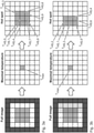
- Fig. 3 outlines schematically the determination of a hot spot for the ideal and non-ideal case:
- the first approach considers the background temperature, which is uninfluenced by the hot spot.
- the second approach focuses on the temperature in the immediate (or contiguous) region surrounding of the detected pixel with the maximal temperature.
- Figure 4 depicts schematically the evaluation of the background temperature
- correction functions are the core of the algorithm, which describe the hot spot size dependent error in temperature measured by the infrared camera. They can be derived from reference or basic measurements where thermocouples are additionally installed for the sake of comparison. With the purpose of generally valid correction functions, it is convenient to vary additionally the object (hot spot) and background temperature:
- the background temperature can be controlled in the measurements for the derivation of the correction functions.
- the resulting hot spot surrounding temperature is implicitly dependent on the background temperature. 4.
- the correction function f corr can be plotted against the number N for different hot spot and surrounding temperatures. Curve fitting is performed to have a global mathematical function which reveals the best fit of the measured errors in dependence on N for the considered range of hot spot and surrounding temperatures, see Fig. 6 . that shows measurement errors against number N of hot spot pixels and correction function, here as a linear function from a curve fitting.
- the different types of points represent measurements with different hot spot and background temperatures.
- the last step of the temperature correction algorithm is to calculate the corrected temperature:
- correction functions f corr can be provided, which actually results from a curve fitting of the error.
- the above described technique of temperature correction allows to improve the accuracy of hot spot temperature detection at a very low cost as only the simple algorithm has to be implemented in the micro controller of the sensor or in the central data aggregation unit. Neither additional complex optics is needed, nor a high-quality IR camera with better or high resolution.
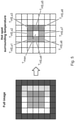
- FIG. 7 shows an exemplary spline interpolation for the non-ideal hot spot.
- interpolation increases the resolution of the image, which improves the characterization of the hot spot size and temperature as well as the surrounding/background temperature compared to the raw image in Fig. 2 b).
- interpolation methods are useful for the derivation of correction functions as well as for the temperature correction algorithm itself. In both cases, the interpolation is carried out beforehand and all further steps are proceeded with the interpolated image of better quality.
- Interpolation results in smooth linear functions between data points in each pixel of the raw image. Indeed, discontinuities, for example caused by a warm cable running through the cold background, can be only captured by the thermal image at the borders of the raw image pixels. In general, interpolation does not support to detect the exact boundaries of discontinuity in the raw image.
- the main benefit is that the interpolation leads to more accurate results. Especially, the temperature correction algorithm becomes less sensitive to changes in the number of hot spot pixels, which reduces oscillatory behaviour during an online temperature monitoring.
Landscapes
- Engineering & Computer Science (AREA)
- Physics & Mathematics (AREA)
- General Physics & Mathematics (AREA)
- Theoretical Computer Science (AREA)
- Computer Vision & Pattern Recognition (AREA)
- Signal Processing (AREA)
- Multimedia (AREA)
- Toxicology (AREA)
- Health & Medical Sciences (AREA)
- Spectroscopy & Molecular Physics (AREA)
- Geometry (AREA)
- Quality & Reliability (AREA)
- Radiation Pyrometers (AREA)
- Image Processing (AREA)
Claims (24)
- Vorrichtung für eine Erfassung warmer Stellen, wobei die Vorrichtung Folgendes umfasst:- eine Eingabeeinheit;- eine Verarbeitungseinheit; und- eine Ausgabeeinheit;wobei die Eingabeeinheit konfiguriert ist, die Verarbeitungseinheit mit einem Bild eines Objektes zu versorgen, das eine warme Stelle besitzt, wobei Bilddaten des Bildes Bilddaten der warmen Stelle umfassen und wobei das Bild durch eine Kamera erfasst wurde;wobei die Verarbeitungseinheit konfiguriert ist, eine Anzahl von Pixeln in dem Bild, die einer Größe der warmen Stelle entsprechen, zu bestimmen;wobei die Verarbeitungseinheit konfiguriert ist, eine mittlere Temperatur für die warme Stelle zu bestimmen, wobei die Bestimmung die Verwendung von Pixelwerten in dem Bild, die der Größe der warmen Stelle entsprechen, und die Anzahl von Pixeln in dem Bild, die der Größe der warmen Stelle entsprechen, umfasst;wobei die Verarbeitungseinheit konfiguriert ist, eine Umgebungstemperatur in dem Bild zu bestimmen, wobei die Bestimmung die Verwendung mindestens eines Pixels in dem Bild, das von den Pixeln in dem Bild, die der Größe der warmen Stelle entsprechen, verschieden ist, umfasst;wobei die Verarbeitungseinheit konfiguriert ist, eine korrigierte Temperatur für die warme Stelle zu bestimmen, wobei die Bestimmung die Verwendung eines Werts eines Korrekturfaktors, die mittlere Temperatur für die warme Stelle und die Umgebungstemperatur umfasst;wobei der Korrekturfaktor mehrere mögliche Werte besitzt und wobei der Wert des Korrekturfaktors, der in der Bestimmung der korrigierten Temperatur für die warme Stelle verwendet wird, als eine Funktion der Anzahl von Pixeln in dem Bild, die der Größe der warmen Stelle entsprechen, bestimmt wird; undwobei die mehreren möglichen Werte des Korrekturfaktors anhand mehrerer Kalibrierungsbilder einer oder mehrerer warmer Stellen, die durch die Kamera und/oder durch mehrere Kameras, die im Wesentlichen dieselben wie die Kamera sind, erfasst werden, und anhand einer oder mehrerer gemessener Temperaturen oder Referenztemperaturen für die eine oder die mehreren warmen Stellen bestimmt werden.
- Vorrichtung nach Anspruch 1, wobei die Verarbeitungseinheit konfiguriert ist, ein Pixel in dem Bild, das einer maximalen Temperatur der warmen Stelle entspricht, zu bestimmen, und wobei die Pixel in dem Bild, die der Größe der warmen Stelle entsprechen, das Pixel in dem Bild, das der maximalen Temperatur der warmen Stelle entspricht, umfassen.
- Vorrichtung nach Anspruch 2, wobei die Verarbeitungseinheit konfiguriert ist, die Pixel in dem Bild, die der Größe der warmen Stelle entsprechen, als die Pixel in dem Bild, die einen Wert innerhalb eines Schwellenbereichs eines Werts des Pixels besitzen, von dem bestimmt wurde, dass es eine maximale Temperatur der warmen Stelle besitzt, zu bestimmen.
- Vorrichtung nach einem der Ansprüche 1-3, wobei die Bestimmung der Umgebungstemperatur die Verwendung einer Anzahl mindestens eines Umgebungspixels in dem Bild, das mit den Pixeln in dem Bild, die der Größe der warmen Stelle entsprechen, zusammenhängt, und mindestens eines Pixelwerts des mindestens einen Umgebungspixels umfasst.
- Vorrichtung nach einem der Ansprüche 1-3, wobei die Bestimmung der Umgebungstemperatur die Verwendung einer Anzahl mindestens eines Umgebungspixels in dem Bild, das nicht mit den Pixeln in dem Bild, die der Größe der warmen Stelle entsprechen, zusammenhängt, und mindestens eines Pixelwerts des mindestens einen Umgebungspixels umfasst.
- Vorrichtung nach einem der Ansprüche 1-5, wobei ein Thermoelement verwendet wird, um die gemessenen Temperaturen bereitzustellen.
- Vorrichtung nach einem der Ansprüche 1-6, wobei die Bestimmung der mehreren möglichen Werte des Korrekturfaktors für jedes Kalibrierungsbild der mehreren Kalibrierungsbilder eine Bestimmung einer Anzahl von Pixeln in dem Kalibrierungsbild, die einer Größe der warmen Stelle entsprechen, eine Bestimmung einer mittleren Temperatur für die warme Stelle in dem Kalibrierungsbild, die eine Verwendung von Pixelwerten der Pixel in dem Kalibrierungsbild, die der Größe der warmen Stelle entsprechen, und der Anzahl von Pixeln in dem Kalibrierungsbild, die einer Größe der warmen Stelle entsprechen, umfasst, und eine Bestimmung einer Umgebungstemperatur in dem Kalibrierungsbild, die eine Verwendung mindestens eines Pixels in dem Kalibrierungsbild, das von Pixeln in dem Kalibrierungsbild, die der Größe der warmen Stelle entsprechen, verschieden ist, umfasst.
- Vorrichtung nach Anspruch 7, wobei die Pixel in dem Kalibrierungsbild, die der Größe der warmen Stelle entsprechen, ein Pixel in dem Kalibrierungsbild, das einer maximalen Temperatur der warmen Stelle entspricht, umfassen und wobei die Pixel in dem Kalibrierungsbild, die der Größe der warmen Stelle entsprechen, als die Pixel in dem Kalibrierungsbild bestimmt werden, die einen Wert innerhalb eines Schwellenbereichs eines Werts des Pixels besitzen, von dem bestimmt wurde, das es die maximale Temperatur der warmen Stelle in dem Kalibrierungsbild besitzt.
- Vorrichtung nach einem der Ansprüche 6-8, wobei die Bestimmung der mehreren möglichen Werte des Korrekturfaktors für jedes Kalibrierungsbild der mehreren Kalibrierungsbilder eine Bestimmung eines Fehlerwerts umfasst, wobei die Bestimmung eine Berechnung eines ersten Werts als die gemessene Temperatur oder die Referenztemperatur für die warme Stelle subtrahiert von der mittleren Temperatur für die warme Stelle in dem Kalibrierungsbild und eine Berechnung eines zweiten Werts als die Umgebungstemperatur für die warme Stelle in dem Kalibrierungsbild subtrahiert von der mittleren Temperatur für die warme Stelle in dem Kalibrierungsbild umfasst und wobei der Fehlerwert als das Verhältnis des ersten Werts zu dem zweiten Wert bestimmt wird.
- Vorrichtung nach einem der Ansprüche 1-9, wobei die Bestimmung der korrigierten Temperatur eine Multiplikation des Korrekturfaktors mit einem Unterschied zwischen der mittleren Temperatur für die warme Stelle in dem Bild und der Umgebungstemperatur in dem Bild und eine Subtraktion dieses von der mittleren Temperatur für die warme Stelle in dem Bild umfasst.
- Vorrichtung nach einem der Ansprüche 1-10, wobei dann, wenn die Verarbeitungseinheit das Bild von der Eingabeeinheit empfängt, und vor einer weiteren Verarbeitung die Verarbeitungseinheit konfiguriert ist, das Bild in ein interpoliertes Bild für eine weitere Verarbeitung umzuwandeln.
- System für eine Erfassung warmer Stellen, wobei das System Folgendes umfasst:- eine Vorrichtung nach einem der Ansprüche 1-11; und- eine Kamera,wobei die Kamera konfiguriert ist, das Bild eines Objektes, das eine warme Stelle besitzt, zu erfassen.
- Niederspannungs-, Mittelspannungs- oder Hochspannungsschaltanlage, die mindestens ein System nach Anspruch 12 umfasst, wobei das Objekt, das eine warme Stelle besitzt, Teil der Schaltanlage ist.
- Verfahren zur Erfassung warmer Stellen, wobei das Verfahren Folgendes umfasst:a) Versorgen einer Verarbeitungseinheit mit einem Bild eines Objektes, das eine warme Stelle besitzt, wobei Bilddaten des Bildes Bilddaten der warmen Stelle umfassen, und wobei das Bild durch eine Kamera erfasst wurde;e) Bestimmen durch die Verarbeitungseinheit einer Anzahl von Pixeln in dem Bild, die einer Größe der warmen Stelle entsprechen;f) Bestimmen durch die Verarbeitungseinheit einer mittleren Temperatur für die warme Stelle, wobei das Bestimmen umfasst, Pixelwerte der Pixel in dem Bild, die der Größe der warmen Stelle entsprechen, und die Anzahl von Pixeln in dem Bild, die der Größe der warmen Stelle entsprechen, zu verwenden;g) Bestimmen durch die Verarbeitungseinheit einer Umgebungstemperatur in dem Bild, wobei das Bestimmen umfasst, mindestens ein Pixel in dem Bild, das von den Pixeln in dem Bild, die der Größe der warmen Stelle entsprechen, verschieden ist, zu verwenden; undh) Bestimmen durch die Verarbeitungseinheit einer korrigierten Temperatur für die warme Stelle, wobei das Bestimmen umfasst, einen Wert eines Korrekturfaktors, die mittlere Temperatur für die warme Stelle und die Umgebungstemperatur zu verwenden;wobei in Schritt h) der Korrekturfaktor mehrere mögliche Werte besitzt und wobei Schritt h) umfasst, den Wert des Korrekturfaktors als eine Funktion der Anzahl von Pixeln in dem Bild, die der Größe der warmen Stelle entsprechen, zu bestimmen; undwobei das Verfahren umfasst, dass Schritt a) die mehreren möglichen Werte des Korrekturfaktors anhand mehrerer Kalibrierungsbilder einer oder mehrerer warmer Stellen, die durch die Kamera und/oder durch mehrere Kameras, die im Wesentlichen dieselben wie die Kamera sind, erfasst werden, und anhand einer oder mehrerer gemessener Temperaturen oder Referenztemperaturen für die eine oder die mehreren warmen Stellen zu bestimmen.
- Verfahren nach Anspruch 14, wobei das Verfahren umfasst, dass Schritt d) durch die Verarbeitungseinheit ein Pixel in dem Bild bestimmt, das einer maximalen Temperatur der warmen Stelle entspricht, und wobei in Schritt e) die Pixel in dem Bild, die der Größe der warmen Stelle entsprechen, das Pixel in dem Bild umfassen, das der maximalen Temperatur der warmen Stelle entspricht.
- Verfahren nach Anspruch 15, wobei Schritt e) umfasst, dass die Verarbeitungseinheit die Pixel in dem Bild, die der Größe der warmen Stelle entsprechen, als die Pixel in dem Bild, die einen Wert innerhalb eines Schwellenbereichs eines Werts des Pixels, von dem bestimmt wurde, dass es eine maximale Temperatur der warmen Stelle besitzt, besitzen, bestimmt.
- Verfahren nach einem der Ansprüche 14-16, wobei Schritt g) umfasst, eine Anzahl mindestens eines Umgebungspixels in dem Bild, das mit den Pixeln in dem Bild, die der Größe der warmen Stelle entsprechen, zusammenhängt, und mindestens einen Pixelwert des mindestens einen Umgebungspixels zu verwenden.
- Verfahren nach einem der Ansprüche 14-16, wobei Schritt g) umfasst, eine Anzahl mindestens eines Umgebungspixels in dem Bild, das nicht mit den Pixeln in Bild, die der Größe der warmen Stelle entsprechen, zusammenhängt, und mindestens einen Pixelwert des mindestens einen Umgebungspixels zu verwenden.
- Verfahren nach einem der Ansprüche 14-18, wobei ein Thermoelement verwendet wird, um die gemessenen Temperaturen bereitzustellen.
- Verfahren nach einem der Ansprüche 14-19, wobei Schritt a) umfasst, für jedes Kalibrierungsbild der mehreren Kalibrierungsbilder eine Anzahl von Pixeln in dem Kalibrierungsbild zu bestimmen, die einer Größe der warmen Stelle entsprechen, eine mittlere Temperatur für die warme Stelle in dem Kalibrierungsbild zu bestimmen, das umfasst, Pixelwerte der Pixel in dem Kalibrierungsbild, die der Größe der warmen Stelle entsprechen, und die Anzahl von Pixeln in dem Kalibrierungsbild, die einer Größe der warmen Stelle entsprechen, zu verwenden, und eine Umgebungstemperatur in dem Kalibrierungsbild zu bestimmen, das umfasst, mindestens ein Pixel in dem Kalibrierungsbild, das von den Pixeln in dem Kalibrierungsbild, die der Größe der warmen Stelle entsprechen, verschieden ist, zu verwenden.
- Verfahren nach Anspruch 20, wobei in Schritt a) die Pixel in dem Kalibrierungsbild, die der Größe der warmen Stelle entsprechen, ein Pixel in dem Kalibrierungsbild umfassen, das einer maximalen Temperatur der warmen Stelle entspricht, und wobei Schritt a) umfasst, die Pixel in dem Kalibrierungsbild, die der Größe der warmen Stelle entsprechen, als die Pixel in dem Kalibrierungsbild, die einen Wert innerhalb eines Schwellenbereichs eines Werts des Pixels besitzen, von dem bestimmt wurde, das es die maximale Temperatur der warmen Stelle in dem Kalibrierungsbild besitzt, zu bestimmen.
- Verfahren nach einem der Ansprüche 19-21, wobei Schritt a) umfasst, für jedes Kalibrierungsbild der mehreren Kalibrierungsbilder einen Fehlerwert zu bestimmen, wobei das Bestimmen umfasst, einen ersten Wert als die gemessene Temperatur oder die Referenztemperatur für die warme Stelle subtrahiert von der mittleren Temperatur für die warme Stelle in dem Kalibrierungsbild zu berechnen und einen zweiten Wert als die Umgebungstemperatur für die warme Stelle in dem Kalibrierungsbild subtrahiert von der mittleren Temperatur für die warme Stelle in dem Kalibrierungsbild zu berechnen und wobei Schritt a) umfasst, den Fehlerwert als das Verhältnis des ersten Werts zu dem zweiten Wert zu bestimmen.
- Verfahren nach einem der Ansprüche 14-22, wobei Schritt h) umfasst, den Korrekturfaktor mit einem Unterschied zwischen der mittleren Temperatur für die warme Stelle in dem Bild und der Umgebungstemperatur in dem Bild zu multiplizieren und dies von der mittleren Temperatur für die warme Stelle in dem Bild zu subtrahieren.
- Verfahren nach einem der Ansprüche 14-23, wobei das Verfahren umfasst, das Schritt c) durch die Verarbeitungseinheit das Bild in ein interpoliertes Bild für eine weitere Verarbeitung umwandelt.
Priority Applications (4)
| Application Number | Priority Date | Filing Date | Title |
|---|---|---|---|
| EP19165287.4A EP3716205B1 (de) | 2019-03-26 | 2019-03-26 | Vorrichtung zum erfassen von hotspots |
| PCT/EP2020/057835 WO2020193422A1 (en) | 2019-03-26 | 2020-03-20 | An apparatus for hot spot sensing |
| CN202080024274.8A CN113678165B (zh) | 2019-03-26 | 2020-03-20 | 用于热点感测的装置 |
| US17/483,834 US12104960B2 (en) | 2019-03-26 | 2021-09-24 | Apparatus for hot spot sensing |
Applications Claiming Priority (1)
| Application Number | Priority Date | Filing Date | Title |
|---|---|---|---|
| EP19165287.4A EP3716205B1 (de) | 2019-03-26 | 2019-03-26 | Vorrichtung zum erfassen von hotspots |
Publications (2)
| Publication Number | Publication Date |
|---|---|
| EP3716205A1 EP3716205A1 (de) | 2020-09-30 |
| EP3716205B1 true EP3716205B1 (de) | 2022-02-23 |
Family
ID=66175136
Family Applications (1)
| Application Number | Title | Priority Date | Filing Date |
|---|---|---|---|
| EP19165287.4A Active EP3716205B1 (de) | 2019-03-26 | 2019-03-26 | Vorrichtung zum erfassen von hotspots |
Country Status (4)
| Country | Link |
|---|---|
| US (1) | US12104960B2 (de) |
| EP (1) | EP3716205B1 (de) |
| CN (1) | CN113678165B (de) |
| WO (1) | WO2020193422A1 (de) |
Families Citing this family (6)
| Publication number | Priority date | Publication date | Assignee | Title |
|---|---|---|---|---|
| EP3706269B1 (de) * | 2019-03-07 | 2022-06-29 | ABB Schweiz AG | Künstliche intelligenz überwachungsvorrichtung mit infrarotbildern zür identifikation von hotspots in einer schaltanlage |
| EP4080450B1 (de) | 2021-04-20 | 2025-06-04 | ABB Schweiz AG | System zur überwachung einer vorrichtung |
| CN113916383B (zh) * | 2021-09-29 | 2023-11-21 | 杭州微影软件有限公司 | 热成像温度测量方法、装置及电子设备 |
| ES3061455T3 (en) * | 2022-01-14 | 2026-04-01 | Abb Schweiz Ag | System for monitoring a switchgear |
| EP4266015B1 (de) * | 2022-04-21 | 2025-10-01 | Abb Schweiz Ag | System zur überwachung einer schaltanlage |
| WO2024243709A1 (en) * | 2023-06-01 | 2024-12-05 | Qeatech Inc. | Method and system for detection and localization of thermal defects |
Family Cites Families (9)
| Publication number | Priority date | Publication date | Assignee | Title |
|---|---|---|---|---|
| US8531562B2 (en) * | 2004-12-03 | 2013-09-10 | Fluke Corporation | Visible light and IR combined image camera with a laser pointer |
| US7661876B2 (en) * | 2007-11-14 | 2010-02-16 | Fluke Corporation | Infrared target temperature correction system and method |
| EP2280460B1 (de) * | 2009-07-27 | 2011-11-16 | ABB Research Ltd. | Leistungsschaltwerk |
| US9224278B2 (en) * | 2011-04-18 | 2015-12-29 | Xerox Corporation | Automated method and system for detecting the presence of a lit cigarette |
| WO2013108955A1 (ko) * | 2012-01-17 | 2013-07-25 | 티.비.티. 주식회사 | 적외선 영상 처리 방법 및 적외선 영상 처리 장치 |
| US8748808B2 (en) * | 2012-05-16 | 2014-06-10 | Institut National D'optique | Detection and correction of a loss of calibration of microbolometer thermal imaging radiometers |
| MX340152B (es) * | 2013-12-19 | 2016-06-08 | Kaplun Mucharrafille Margarita | Sistema y metodo para calibracion y/o caracterizacion de instrumentos de medicion de temperatura por telemetria. |
| CN108603790B (zh) * | 2015-12-09 | 2020-09-25 | 菲力尔系统公司 | 基于无人机系统的热成像系统和方法 |
| JP2019526304A (ja) * | 2016-06-29 | 2019-09-19 | ニラマイ・ヘルス・アナリティックス・ピーブイティー・エルティーディ | 胸部サーモグラフィ画像による悪性腫瘍性組織のホルモン受容体状態の分類 |
-
2019
- 2019-03-26 EP EP19165287.4A patent/EP3716205B1/de active Active
-
2020
- 2020-03-20 CN CN202080024274.8A patent/CN113678165B/zh active Active
- 2020-03-20 WO PCT/EP2020/057835 patent/WO2020193422A1/en not_active Ceased
-
2021
- 2021-09-24 US US17/483,834 patent/US12104960B2/en active Active
Also Published As
| Publication number | Publication date |
|---|---|
| EP3716205A1 (de) | 2020-09-30 |
| CN113678165A (zh) | 2021-11-19 |
| WO2020193422A1 (en) | 2020-10-01 |
| CN113678165B (zh) | 2024-12-13 |
| US12104960B2 (en) | 2024-10-01 |
| US20220011164A1 (en) | 2022-01-13 |
Similar Documents
| Publication | Publication Date | Title |
|---|---|---|
| EP3716205B1 (de) | Vorrichtung zum erfassen von hotspots | |
| US9804031B2 (en) | Apparatus and method to calculate energy dissipated from an object | |
| CN110793635B (zh) | 热成像测温方法、装置及终端设备 | |
| CN106017695B (zh) | 基于运动状态估计的自适应红外非均匀性校正方法 | |
| CA2252057C (en) | Method for determining pressure | |
| CN113834571A (zh) | 一种目标测温方法、装置及测温系统 | |
| US9696210B2 (en) | Extended temperature range mapping process of a furnace enclosure using various device settings | |
| US20190182439A1 (en) | Thermal image processing system and method | |
| JP2019213193A (ja) | 赤外線撮像装置及びそれに用いられるプログラム | |
| US20150355030A1 (en) | Equipment and method for intensity-temperature transformation of imaging system | |
| CN107606493B (zh) | 一种管道泄漏检测系统 | |
| JP2012008058A (ja) | 温度測定装置 | |
| CN117036497B (zh) | 汽车影像系统的图像处理及摄像头标定方法和相关装置 | |
| WO2001096814A2 (en) | System and method for converting analog data to digital data | |
| Hidaka et al. | Scheme for improving the spatial resolution of thermal images for objects with different emissivity | |
| CN111207833A (zh) | 一种基于图像数据归一化技术的测温方法 | |
| US11761821B2 (en) | System and method for thermal imaging | |
| Dziarski et al. | Effect of unsharpness on the result of thermovision diagnostics of electronic components | |
| JP7638409B1 (ja) | 赤外線撮像装置および赤外線撮像装置の出力値補正方法 | |
| CN110111277A (zh) | 一种平面热像图修补方法及装置 | |
| KR102639542B1 (ko) | 열화상 카메라를 이용한 발열 감지 시스템의 온도 감지 방법 및 장치 | |
| WO2025254632A1 (en) | Non-uniformity correction method | |
| CN121785362A (zh) | 一种基于红外图像的架空集电线路无人机昼夜巡检方法 | |
| CN114616445A (zh) | 基于热辐射探测器的测温方法、装置及热辐射探测器 | |
| JP2008035365A (ja) | 遠赤外線撮像システム及び遠赤外線撮像方法 |
Legal Events
| Date | Code | Title | Description |
|---|---|---|---|
| PUAI | Public reference made under article 153(3) epc to a published international application that has entered the european phase |
Free format text: ORIGINAL CODE: 0009012 |
|
| STAA | Information on the status of an ep patent application or granted ep patent |
Free format text: STATUS: THE APPLICATION HAS BEEN PUBLISHED |
|
| AK | Designated contracting states |
Kind code of ref document: A1 Designated state(s): AL AT BE BG CH CY CZ DE DK EE ES FI FR GB GR HR HU IE IS IT LI LT LU LV MC MK MT NL NO PL PT RO RS SE SI SK SM TR |
|
| AX | Request for extension of the european patent |
Extension state: BA ME |
|
| STAA | Information on the status of an ep patent application or granted ep patent |
Free format text: STATUS: REQUEST FOR EXAMINATION WAS MADE |
|
| 17P | Request for examination filed |
Effective date: 20210212 |
|
| RBV | Designated contracting states (corrected) |
Designated state(s): AL AT BE BG CH CY CZ DE DK EE ES FI FR GB GR HR HU IE IS IT LI LT LU LV MC MK MT NL NO PL PT RO RS SE SI SK SM TR |
|
| GRAP | Despatch of communication of intention to grant a patent |
Free format text: ORIGINAL CODE: EPIDOSNIGR1 |
|
| STAA | Information on the status of an ep patent application or granted ep patent |
Free format text: STATUS: GRANT OF PATENT IS INTENDED |
|
| INTG | Intention to grant announced |
Effective date: 20211029 |
|
| GRAS | Grant fee paid |
Free format text: ORIGINAL CODE: EPIDOSNIGR3 |
|
| GRAA | (expected) grant |
Free format text: ORIGINAL CODE: 0009210 |
|
| STAA | Information on the status of an ep patent application or granted ep patent |
Free format text: STATUS: THE PATENT HAS BEEN GRANTED |
|
| AK | Designated contracting states |
Kind code of ref document: B1 Designated state(s): AL AT BE BG CH CY CZ DE DK EE ES FI FR GB GR HR HU IE IS IT LI LT LU LV MC MK MT NL NO PL PT RO RS SE SI SK SM TR |
|
| RAP3 | Party data changed (applicant data changed or rights of an application transferred) |
Owner name: ABB SCHWEIZ AG |
|
| REG | Reference to a national code |
Ref country code: GB Ref legal event code: FG4D |
|
| REG | Reference to a national code |
Ref country code: CH Ref legal event code: EP |
|
| REG | Reference to a national code |
Ref country code: AT Ref legal event code: REF Ref document number: 1471042 Country of ref document: AT Kind code of ref document: T Effective date: 20220315 |
|
| REG | Reference to a national code |
Ref country code: IE Ref legal event code: FG4D |
|
| REG | Reference to a national code |
Ref country code: DE Ref legal event code: R096 Ref document number: 602019011761 Country of ref document: DE |
|
| REG | Reference to a national code |
Ref country code: LT Ref legal event code: MG9D |
|
| REG | Reference to a national code |
Ref country code: NL Ref legal event code: MP Effective date: 20220223 |
|
| REG | Reference to a national code |
Ref country code: AT Ref legal event code: MK05 Ref document number: 1471042 Country of ref document: AT Kind code of ref document: T Effective date: 20220223 |
|
| PG25 | Lapsed in a contracting state [announced via postgrant information from national office to epo] |
Ref country code: SE Free format text: LAPSE BECAUSE OF FAILURE TO SUBMIT A TRANSLATION OF THE DESCRIPTION OR TO PAY THE FEE WITHIN THE PRESCRIBED TIME-LIMIT Effective date: 20220223 Ref country code: RS Free format text: LAPSE BECAUSE OF FAILURE TO SUBMIT A TRANSLATION OF THE DESCRIPTION OR TO PAY THE FEE WITHIN THE PRESCRIBED TIME-LIMIT Effective date: 20220223 Ref country code: PT Free format text: LAPSE BECAUSE OF FAILURE TO SUBMIT A TRANSLATION OF THE DESCRIPTION OR TO PAY THE FEE WITHIN THE PRESCRIBED TIME-LIMIT Effective date: 20220623 Ref country code: NO Free format text: LAPSE BECAUSE OF FAILURE TO SUBMIT A TRANSLATION OF THE DESCRIPTION OR TO PAY THE FEE WITHIN THE PRESCRIBED TIME-LIMIT Effective date: 20220523 Ref country code: NL Free format text: LAPSE BECAUSE OF FAILURE TO SUBMIT A TRANSLATION OF THE DESCRIPTION OR TO PAY THE FEE WITHIN THE PRESCRIBED TIME-LIMIT Effective date: 20220223 Ref country code: LT Free format text: LAPSE BECAUSE OF FAILURE TO SUBMIT A TRANSLATION OF THE DESCRIPTION OR TO PAY THE FEE WITHIN THE PRESCRIBED TIME-LIMIT Effective date: 20220223 Ref country code: HR Free format text: LAPSE BECAUSE OF FAILURE TO SUBMIT A TRANSLATION OF THE DESCRIPTION OR TO PAY THE FEE WITHIN THE PRESCRIBED TIME-LIMIT Effective date: 20220223 Ref country code: ES Free format text: LAPSE BECAUSE OF FAILURE TO SUBMIT A TRANSLATION OF THE DESCRIPTION OR TO PAY THE FEE WITHIN THE PRESCRIBED TIME-LIMIT Effective date: 20220223 Ref country code: BG Free format text: LAPSE BECAUSE OF FAILURE TO SUBMIT A TRANSLATION OF THE DESCRIPTION OR TO PAY THE FEE WITHIN THE PRESCRIBED TIME-LIMIT Effective date: 20220523 |
|
| PG25 | Lapsed in a contracting state [announced via postgrant information from national office to epo] |
Ref country code: PL Free format text: LAPSE BECAUSE OF FAILURE TO SUBMIT A TRANSLATION OF THE DESCRIPTION OR TO PAY THE FEE WITHIN THE PRESCRIBED TIME-LIMIT Effective date: 20220223 Ref country code: LV Free format text: LAPSE BECAUSE OF FAILURE TO SUBMIT A TRANSLATION OF THE DESCRIPTION OR TO PAY THE FEE WITHIN THE PRESCRIBED TIME-LIMIT Effective date: 20220223 Ref country code: GR Free format text: LAPSE BECAUSE OF FAILURE TO SUBMIT A TRANSLATION OF THE DESCRIPTION OR TO PAY THE FEE WITHIN THE PRESCRIBED TIME-LIMIT Effective date: 20220524 Ref country code: FI Free format text: LAPSE BECAUSE OF FAILURE TO SUBMIT A TRANSLATION OF THE DESCRIPTION OR TO PAY THE FEE WITHIN THE PRESCRIBED TIME-LIMIT Effective date: 20220223 Ref country code: AT Free format text: LAPSE BECAUSE OF FAILURE TO SUBMIT A TRANSLATION OF THE DESCRIPTION OR TO PAY THE FEE WITHIN THE PRESCRIBED TIME-LIMIT Effective date: 20220223 |
|
| PG25 | Lapsed in a contracting state [announced via postgrant information from national office to epo] |
Ref country code: IS Free format text: LAPSE BECAUSE OF FAILURE TO SUBMIT A TRANSLATION OF THE DESCRIPTION OR TO PAY THE FEE WITHIN THE PRESCRIBED TIME-LIMIT Effective date: 20220623 |
|
| PG25 | Lapsed in a contracting state [announced via postgrant information from national office to epo] |
Ref country code: SM Free format text: LAPSE BECAUSE OF FAILURE TO SUBMIT A TRANSLATION OF THE DESCRIPTION OR TO PAY THE FEE WITHIN THE PRESCRIBED TIME-LIMIT Effective date: 20220223 Ref country code: SK Free format text: LAPSE BECAUSE OF FAILURE TO SUBMIT A TRANSLATION OF THE DESCRIPTION OR TO PAY THE FEE WITHIN THE PRESCRIBED TIME-LIMIT Effective date: 20220223 Ref country code: RO Free format text: LAPSE BECAUSE OF FAILURE TO SUBMIT A TRANSLATION OF THE DESCRIPTION OR TO PAY THE FEE WITHIN THE PRESCRIBED TIME-LIMIT Effective date: 20220223 Ref country code: EE Free format text: LAPSE BECAUSE OF FAILURE TO SUBMIT A TRANSLATION OF THE DESCRIPTION OR TO PAY THE FEE WITHIN THE PRESCRIBED TIME-LIMIT Effective date: 20220223 Ref country code: DK Free format text: LAPSE BECAUSE OF FAILURE TO SUBMIT A TRANSLATION OF THE DESCRIPTION OR TO PAY THE FEE WITHIN THE PRESCRIBED TIME-LIMIT Effective date: 20220223 Ref country code: CZ Free format text: LAPSE BECAUSE OF FAILURE TO SUBMIT A TRANSLATION OF THE DESCRIPTION OR TO PAY THE FEE WITHIN THE PRESCRIBED TIME-LIMIT Effective date: 20220223 |
|
| REG | Reference to a national code |
Ref country code: CH Ref legal event code: PL |
|
| REG | Reference to a national code |
Ref country code: DE Ref legal event code: R097 Ref document number: 602019011761 Country of ref document: DE |
|
| PG25 | Lapsed in a contracting state [announced via postgrant information from national office to epo] |
Ref country code: MC Free format text: LAPSE BECAUSE OF FAILURE TO SUBMIT A TRANSLATION OF THE DESCRIPTION OR TO PAY THE FEE WITHIN THE PRESCRIBED TIME-LIMIT Effective date: 20220223 Ref country code: AL Free format text: LAPSE BECAUSE OF FAILURE TO SUBMIT A TRANSLATION OF THE DESCRIPTION OR TO PAY THE FEE WITHIN THE PRESCRIBED TIME-LIMIT Effective date: 20220223 |
|
| REG | Reference to a national code |
Ref country code: BE Ref legal event code: MM Effective date: 20220331 |
|
| PLBE | No opposition filed within time limit |
Free format text: ORIGINAL CODE: 0009261 |
|
| STAA | Information on the status of an ep patent application or granted ep patent |
Free format text: STATUS: NO OPPOSITION FILED WITHIN TIME LIMIT |
|
| PG25 | Lapsed in a contracting state [announced via postgrant information from national office to epo] |
Ref country code: LU Free format text: LAPSE BECAUSE OF NON-PAYMENT OF DUE FEES Effective date: 20220326 Ref country code: LI Free format text: LAPSE BECAUSE OF NON-PAYMENT OF DUE FEES Effective date: 20220331 Ref country code: IE Free format text: LAPSE BECAUSE OF NON-PAYMENT OF DUE FEES Effective date: 20220326 Ref country code: CH Free format text: LAPSE BECAUSE OF NON-PAYMENT OF DUE FEES Effective date: 20220331 |
|
| 26N | No opposition filed |
Effective date: 20221124 |
|
| PG25 | Lapsed in a contracting state [announced via postgrant information from national office to epo] |
Ref country code: SI Free format text: LAPSE BECAUSE OF FAILURE TO SUBMIT A TRANSLATION OF THE DESCRIPTION OR TO PAY THE FEE WITHIN THE PRESCRIBED TIME-LIMIT Effective date: 20220223 Ref country code: BE Free format text: LAPSE BECAUSE OF NON-PAYMENT OF DUE FEES Effective date: 20220331 |
|
| PG25 | Lapsed in a contracting state [announced via postgrant information from national office to epo] |
Ref country code: IT Free format text: LAPSE BECAUSE OF FAILURE TO SUBMIT A TRANSLATION OF THE DESCRIPTION OR TO PAY THE FEE WITHIN THE PRESCRIBED TIME-LIMIT Effective date: 20220223 |
|
| GBPC | Gb: european patent ceased through non-payment of renewal fee |
Effective date: 20230326 |
|
| PG25 | Lapsed in a contracting state [announced via postgrant information from national office to epo] |
Ref country code: GB Free format text: LAPSE BECAUSE OF NON-PAYMENT OF DUE FEES Effective date: 20230326 |
|
| PG25 | Lapsed in a contracting state [announced via postgrant information from national office to epo] |
Ref country code: GB Free format text: LAPSE BECAUSE OF NON-PAYMENT OF DUE FEES Effective date: 20230326 |
|
| PG25 | Lapsed in a contracting state [announced via postgrant information from national office to epo] |
Ref country code: MK Free format text: LAPSE BECAUSE OF FAILURE TO SUBMIT A TRANSLATION OF THE DESCRIPTION OR TO PAY THE FEE WITHIN THE PRESCRIBED TIME-LIMIT Effective date: 20220223 Ref country code: CY Free format text: LAPSE BECAUSE OF FAILURE TO SUBMIT A TRANSLATION OF THE DESCRIPTION OR TO PAY THE FEE WITHIN THE PRESCRIBED TIME-LIMIT Effective date: 20220223 |
|
| PG25 | Lapsed in a contracting state [announced via postgrant information from national office to epo] |
Ref country code: HU Free format text: LAPSE BECAUSE OF FAILURE TO SUBMIT A TRANSLATION OF THE DESCRIPTION OR TO PAY THE FEE WITHIN THE PRESCRIBED TIME-LIMIT; INVALID AB INITIO Effective date: 20190326 |
|
| PG25 | Lapsed in a contracting state [announced via postgrant information from national office to epo] |
Ref country code: MT Free format text: LAPSE BECAUSE OF FAILURE TO SUBMIT A TRANSLATION OF THE DESCRIPTION OR TO PAY THE FEE WITHIN THE PRESCRIBED TIME-LIMIT Effective date: 20220223 |
|
| PG25 | Lapsed in a contracting state [announced via postgrant information from national office to epo] |
Ref country code: TR Free format text: LAPSE BECAUSE OF FAILURE TO SUBMIT A TRANSLATION OF THE DESCRIPTION OR TO PAY THE FEE WITHIN THE PRESCRIBED TIME-LIMIT Effective date: 20220223 |
|
| PGFP | Annual fee paid to national office [announced via postgrant information from national office to epo] |
Ref country code: DE Payment date: 20260319 Year of fee payment: 8 |
|
| PGFP | Annual fee paid to national office [announced via postgrant information from national office to epo] |
Ref country code: FR Payment date: 20260320 Year of fee payment: 8 |